1. Introduction
Nowadays, mechatronics and electromechanical systems have applications in automated and manufacturing industries [
1], medical devices [
2,
3] and many more. Demand for these systems, which are designed to convert electrical energy to mechanical energy, has dramatically increased. To create a novel electromechanical system, multiple engineers in different disciplines, including mechanical engineers, electrical engineers, and software and system engineers may be involved.
Most electromechanical systems include sensors as data acquisition part of the system, motion components like actuators and motors to produce mechanical movements, and one or multiple computational parts [
4]. The latter are usually computers, programmable chips or microcontrollers to control the system performance. The system is fueled by a separate or embedded power supply.
Challenges and Motivations in Electromechanical System Development
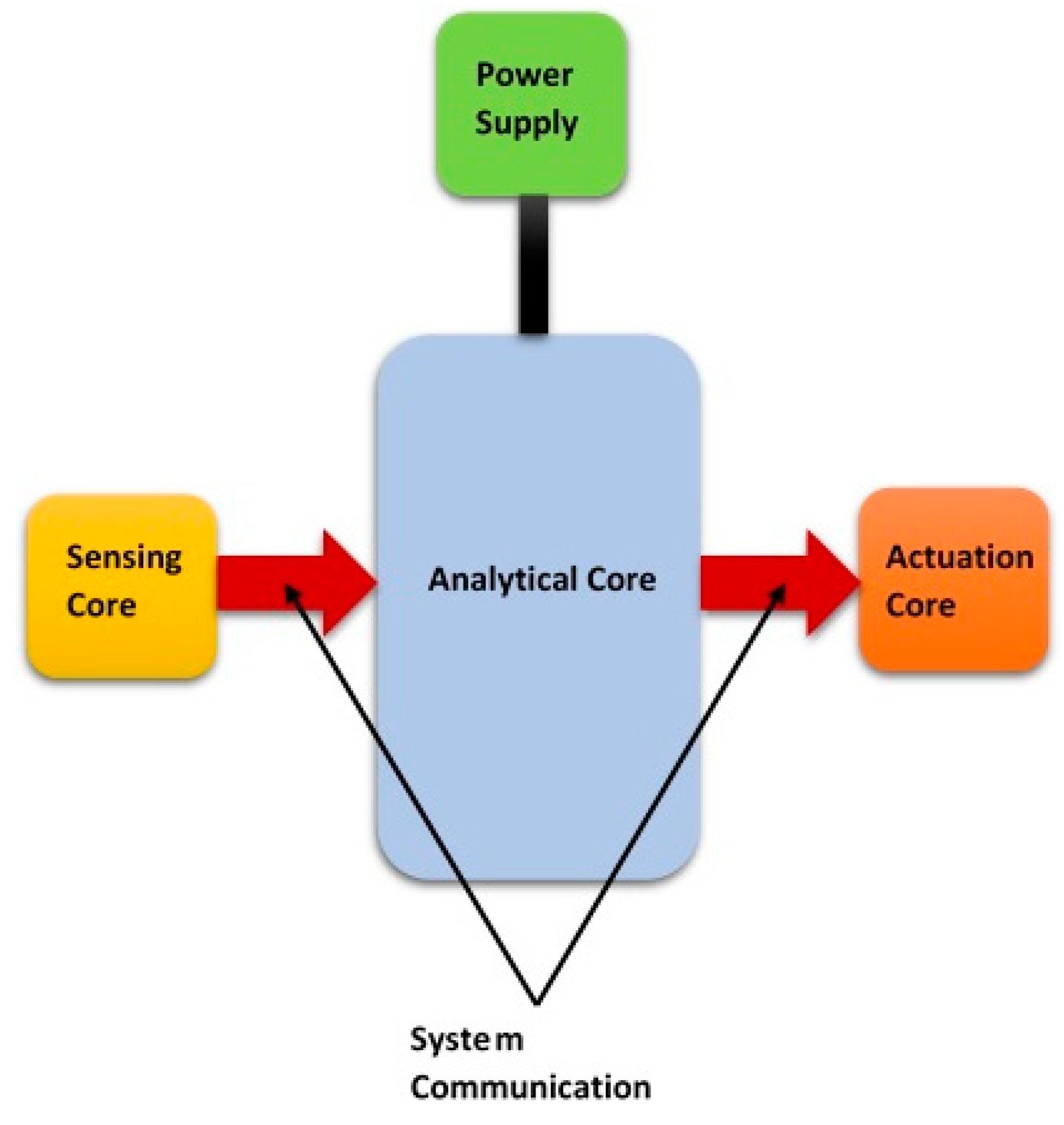
Every day, engineers work to develop new devices and apparatuses, or improve the current ones to obtain better outcomes. Doing this is possible when available or possible components are properly considered, and the functionality and limitation of each part is recognized. As an example, we can consider an engineer who aims to design a fire alarm system to alert and activate fire protection devices in case of an emergency. As the first step, the engineer needs to choose a fire detection method, and then proceeds to the selection and design of an analytical module to receive and analyze signals from the detector. The next step is to design and add an actuation part to the system to perform the needed actions, such as triggering an alarm and activating fire protection system in case of fire or smoke detection. In short, the fire alarm system should include a sensory core to detect fire, an analytical module to analyze sensors signals and send motion control commands to actuation part which trigger an alarming sound and control fire protection devices. All these parts of the system may send and receive signals to communicate and transmit data.
A conventional fire detection system includes fire detectors such, as smoke and heat detectors; actuators, such as sprinklers and smoke ventilators; and a receiver to receive analog signals when a fire is detected. The fire detector causes a short circuit in the system, which leads to the increase of the current in the analog signal line. When the receiver receives the current beyond a threshold, it perceives a fire and turns on the actuation system.
If the system includes more than one detector and actuator connected to the same receiver, the receiver perceives increased current from any detectors and warns the fire existence; however, it cannot distinguish the location of the detector signaling fire or the area that fire has occurred.
Lee et. al. [
5] proposed a network-based fire-detection system to remove this issue. In their fire-detection system, the analog data transmission to receiver is substituted by a Controller Area Network (CAN). Using this method, a unique address is assigned to each detector which can be used by receiver to identify the signaling detector and the location of fire.
Chandana et. al.’s [
6] proposed surveillance system is another example of a new electromechanical apparatus development. The system is a portable monitoring device to sense the door movement, capture the picture and email it to the user, to let them handle the burglary situation immediately. The device hardware includes an Inertial Measurement Unit (IMU), which detects and signals the door movement, using its embedded gyroscope sensor. The signal is sent to a Raspberry Pi (model B) [
7], which is a microcontroller equipped with Linux operating system. The communication of the sensor with this board is through Inter IC (I2C) bus and the operating system as well, as user data are stored in an external Secure Digital (SD) card. The power supply is through micro USB connection to the power. The pictures are taken with Raspberry Pi camera.
These examples show the importance of each part of the system to accomplish desired tasks.
To develop a new system, the first step is to select the components and design mechanical parts. At this level, the designer must consider the expected system function and design a strategy to perform desired actions in a cost-effective and reliable method. Based on the proposed strategy, other components are designed or selected from the market.
The next step is to install and connect the components, build the hardware and control the system to perform its designated tasks. The control system is designed, and software programs are developed at this level of system development.
The final step is to test and debug the system, remove faulty functions and improve the device performance.
In this paper, we aim to discuss the basic requirements for both the hardware and software components of electromechanical system development.
2. System Components
Most electromechanical systems include several sensors, actuators, embedded controllers, such as computers, microcontrollers or programmable chips [
8], and a power supply system. Sensors and actuators are elements of modern machines and have applications in the consumer, scientific and industrial fields [
9]. Sensors are designed in both macro- and micro-/nano-scales to create or obtain data. They can track environmental information, such as temperature, pressure, speed and acceleration [
10]. They are used to detect changes or send information to connected components or devices. We cannot imagine most electronic machines and devices without sensors. These technological devices help to design systems with routine tasks, and aid industries in complex processes.
A microcontroller is a small portable computer designed for embedded applications. It contains one or more processors with memory. Although microcontrollers are less complex than a system on a chip (SoC), they are programmable to communicate with other mechanical or electrical components, including sensors and actuators, through input/output peripherals.
Controllers and microcontrollers are mostly embedded into the system to automatically control other products. They have applications in devices, from toys and telephones to automobile engine control system and power tools. When controllers are embedded in a system, they can provide real-time responses to certain events by sending interrupt signals to the processor. A controller provides an on-chip memory to store software programs. Usually, language codes provided by the software developer are converted to compact machine code, using compilers and assemblers, and the code is stored in the controller memory for automatic control. One of the most applicable coding languages for this purpose is embedded C/C++.
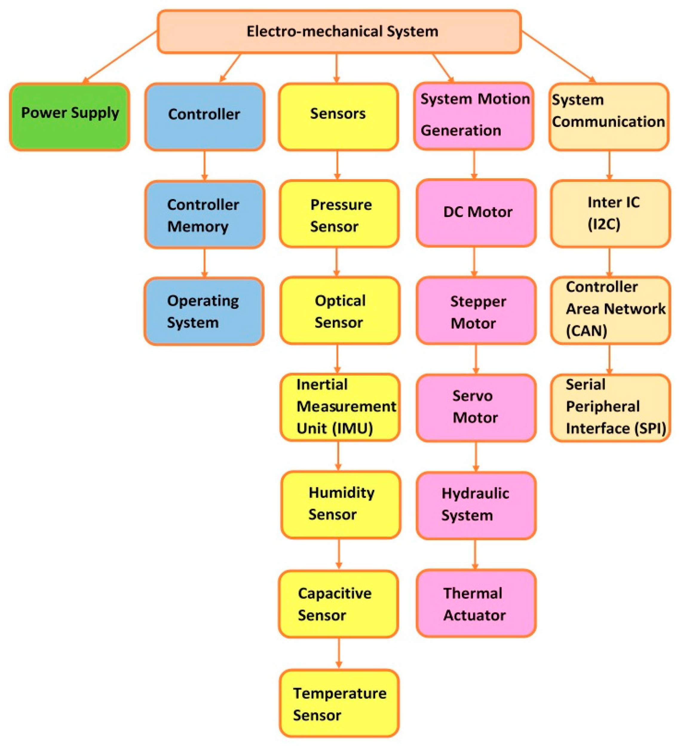
Figure 1 shows the schematic of an electromechanical system. We have summarized all the system components that we discuss in this paper in the flowchart shown in
Figure 2.
3. Sensors
Sensors are designed and utilized in electromechanical systems to detect environmental events or changes and send the data to other parts, especially the analytical core of the system. There are several different sensors available in the market for various applications. In this section, we discuss six common types of sensors and their working principles.
3.1. Pressure Sensors
The pressure sensor can measure pressure or stress by converting the detected pressure into an electrical signal. The electrical signal can be in the form of a small current, usually between 4 and 20 milli amps, or a voltage signal of between 0 and 5 volts.
Many of pressure sensors utilize piezoelectric effect [
11] in which the applied stress to a specific type of solid material creates an electric charge in response [
12].
In pressure sensors, the created electrical charge from piezoelectricity is measured to detect and determine the amount of pressure. There are three common industrial types of pressure sensors:
Gauge pressure sensors: The pressure is measured in reference to atmospheric pressure.
Absolute pressure sensor: The pressure is measured against absolute vacuum.
Differential pressure sensors: The pressure is measured in reference to a specific and predetermined pressure.
3.2. Optical Sensors
Optical sensors convert light rays into electrical signals, to measure a physical property of light, such as intensity, frequency or wavelength. The application of these sensors is in contact-less detection of objects and counting parts. Most of these sensors work based on the photoelectric effect, which is generated when light hits the surface of a solid metal and the photons interact with crystalline lattice of semiconductor to generate free electrons, termed photoelectrons.
The most common industrial optical sensors are photoconductive, photovoltaic and photodiode sensors [
13]. The electrical conductivity of photoconductive devices increases when they are exposed to light. These devices can measure change in electrical resistance to determine the property of incident light. The photovoltaic or solar cells measure the change in created output voltage after they receive light rays, while photodiodes measure the output current to convert the amount of incident light into an electrical signal.
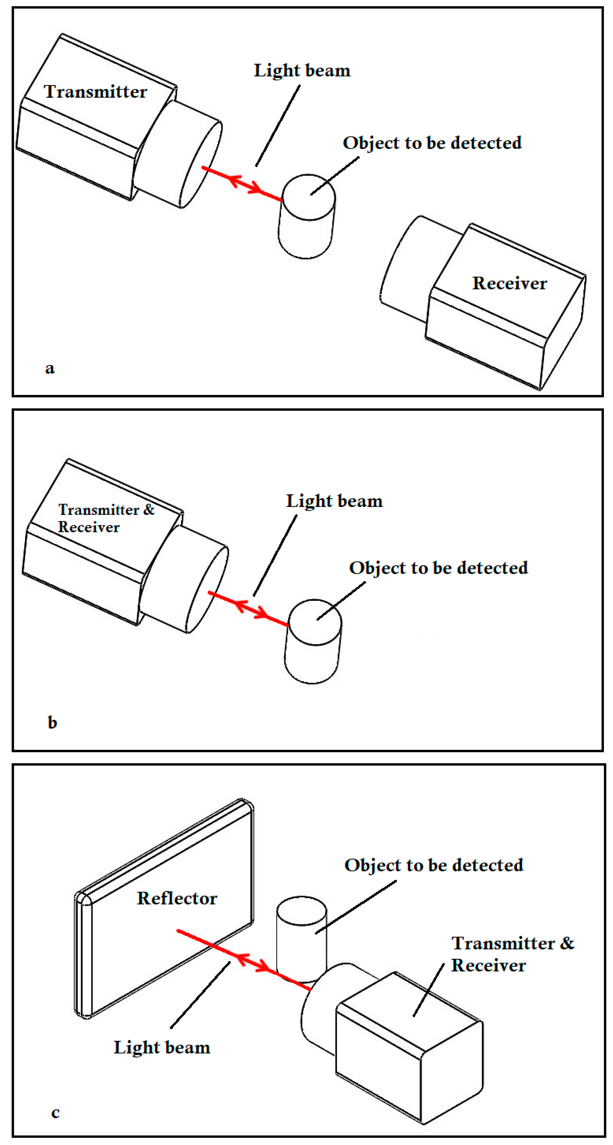
The operating principle of optical sensors is to transmit a light beam. The emitted light beam is reflected or interrupted by the object that is detected by the optical sensor. The interruption or reflection of the light is received and evaluated by the receiver. The transmitter and receiver are placed in different positions in different optical sensors. In through-beam sensors, they are placed opposite to each other. The emitted light beam is interrupted by the target object and thereby provides a signal to the receiver. In defuse reflection sensors, the transmitter and receiver are placed in the same place. The transmitted light beam is reflected by the object and directed back to the receiver. Like diffuse reflection sensors, the transmitter and receiver in retro-reflective sensors are in the same place, but the emitted light beam hits a separate reflector and is reflected to the receiver. The target object interrupts the light beam, which is interpreted as a detection signal by receiver (
Figure 3).
3.3. Inertial Measurement Units
An Inertial Measurement Unit (IMU) comprises a three-axis accelerometer and a three-axis gyroscope, to measure linear acceleration and angular velocity in three directions [
14,
15]. Using these data, the object position and orientation can be determined.
Some IMU units also have a built-in magnetometer to provide compass information, which can be useful to specify the three axes and roll, pitch and yaw directions for IMU. Unfortunately, the magnetic device is very sensitive to the magnetic field of the environment.
The calculated positions of the object from gyroscopes typically suffers from small accumulated errors from point to point, causing a gradual difference between the calculated position and the actual value [
16]. There are several methods and algorithms to reduce the IMU drift, such as using multiple IMUs or employing model-based techniques like the extended Kalman filter to filter noise and reduce the error in each step of position calculation [
17].
3.4. Humidity Sensors
A humidity sensor detects changes in moisture and measures and reports relative humidity by sending electrical signals. The two common types of humidity sensors are capacitive and resistive sensors [
18].
The capacitive humidity sensor consists of a thin strip of polymer or inorganic material placed between two conductive electrodes. The aluminum oxide is the common material used for this purpose. The material is water absorbent, and when the relative humidity increases, it absorbs water, which has a high dielectric constant and, hence, increases the electrical capacity of the sensor. By applying AC voltage across the two electrodes, the current passes through the sensor, and based on the amount of the passed current, the change in electrical capacity and, consequently, the relative humidity is measured.
Resistive humidity sensors consist of a thin strip of water absorbent ceramic or polymer between metal electrodes which absorbs water vapor and increases conductivity of the sensor by disassociating functional ionic groups across the surface of the salt medium. The electrical resistance is the quantity that is measured to determine the relative humidity.
3.5. Capacitive Sensors
The capacitive sensor consists of a conductive element, or plate connected to a circuit. An alternating voltage is applied to the circuit which generates an electric field. If an object is placed in this electric field, it can serve as a second element to form a capacitor with the sensor internal plate. The capacitor dielectric material is the air in the gap between sensor internal element and the external object. Since the capacitance of this sensor is greater for larger and closer objects, the sensor measures this electrical property to sense the external object, determine its size and sense its proximity to the sensor [
19].
3.6. Temperature Sensors
The purpose of temperature sensors is to measure the environmental temperature and report it in the form of electrical signals. The four common types of temperature sensors are as follows [
20]:
The semiconductor-based temperature sensor: This kind of sensor includes thin wafers of silicon to form diodes operating with reverse bias. The sensor has small capacitance and low leakage of current, which is proportional to the absolute temperature. By measuring the leakage current, the temperature is determined.
The resistance-based temperature sensor: This sensor includes a piece of metal, such as a wire made of pure platinum, nickel or copper. Increase or decrease of the temperature causes the change in measured material resistance and the temperature can be calculated based on the accurate formulation describing resistance/temperature relationship of the metal.
Thermistor: Like resistance sensors, the measurement of the temperature by this sensor is based on the change of the material resistance. However, the material in thermistor is not a pure metal. It is generally a ceramic or polymer. In negative temperature coefficient (NTC)-types of thermistors, the resistance of material decreases when temperature increases. In positive temperature coefficient (PTC) types, when the temperature rises, the material resistance also increases.
Thermocouple: This sensor consists of two electrical conductors made from different metals. The conductors are usually in the form of two wire legs, with one end welded together to form an electrical junction. The change in temperature produces a voltage, which is measured, and the corresponding temperature is calculated.
4. System Motion Generation Components
Many electromechanical systems have motion generation parts to produce movements for the system. In this section, various types of these components are discussed.
4.1. DC Motors
DC motors are electromagnetic devices that convert electrical energy into mechanical energy. The working principle of DC motors is based on interaction of magnetic fields and conductors. When a current is passed through a conductor in a magnetic field, a force is generated and applied to the conductor, causing it to move.
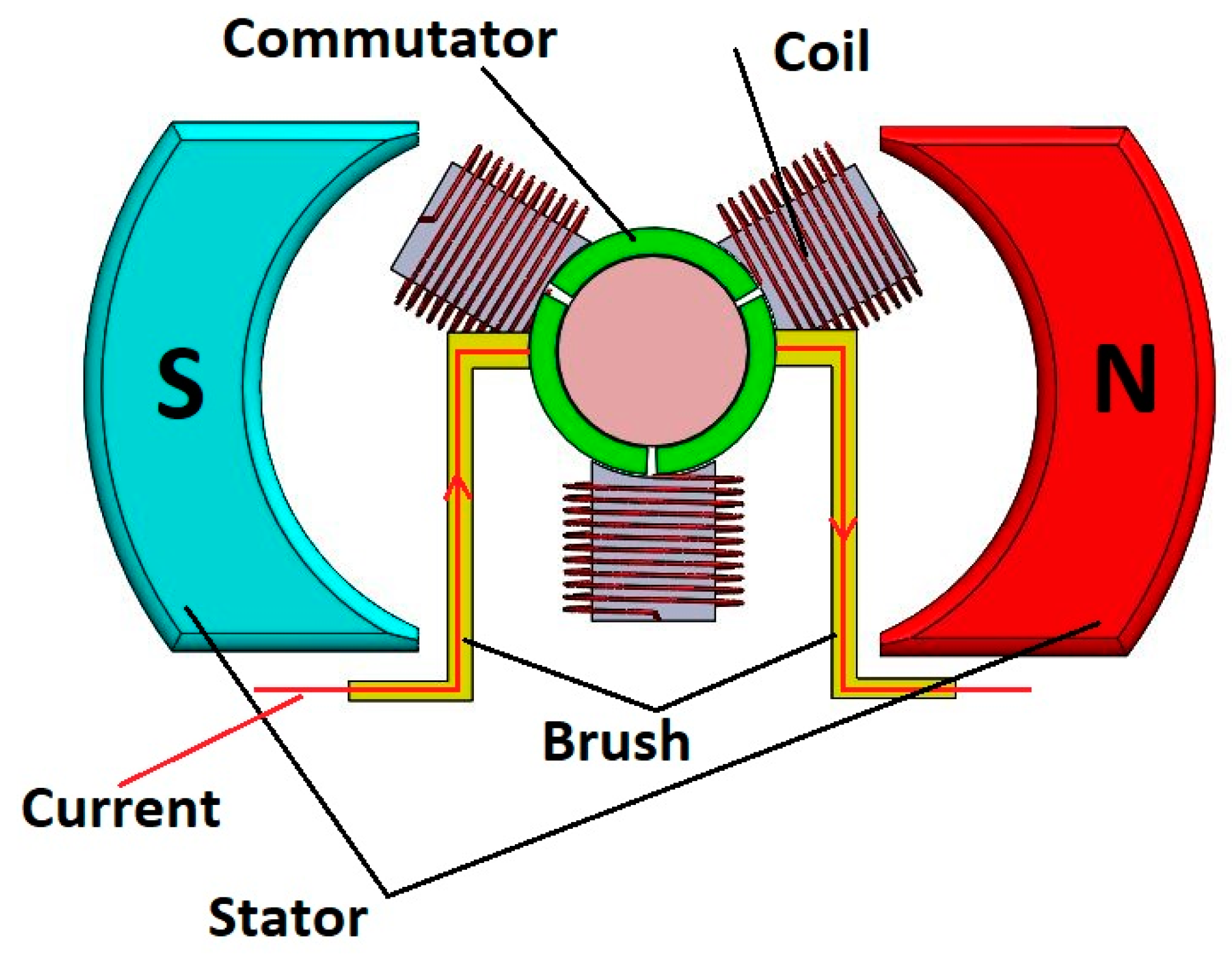
There are two common types of DC motors [
21]. Brushed DC motors consist of two stationary metallic brushes, a rotor, a commutator, a pair of magnets or stator and several coils connected to segments of the commutator and surrounded by magnetic field. The current is provided through coils from brushes which are in contact with segments of the commutator. The generated forces in the coils cause the rotor of the motor to rotate and create rotary motion. The rotor is in contact with coils, and they rotate in the magnetic field together (
Figure 4).
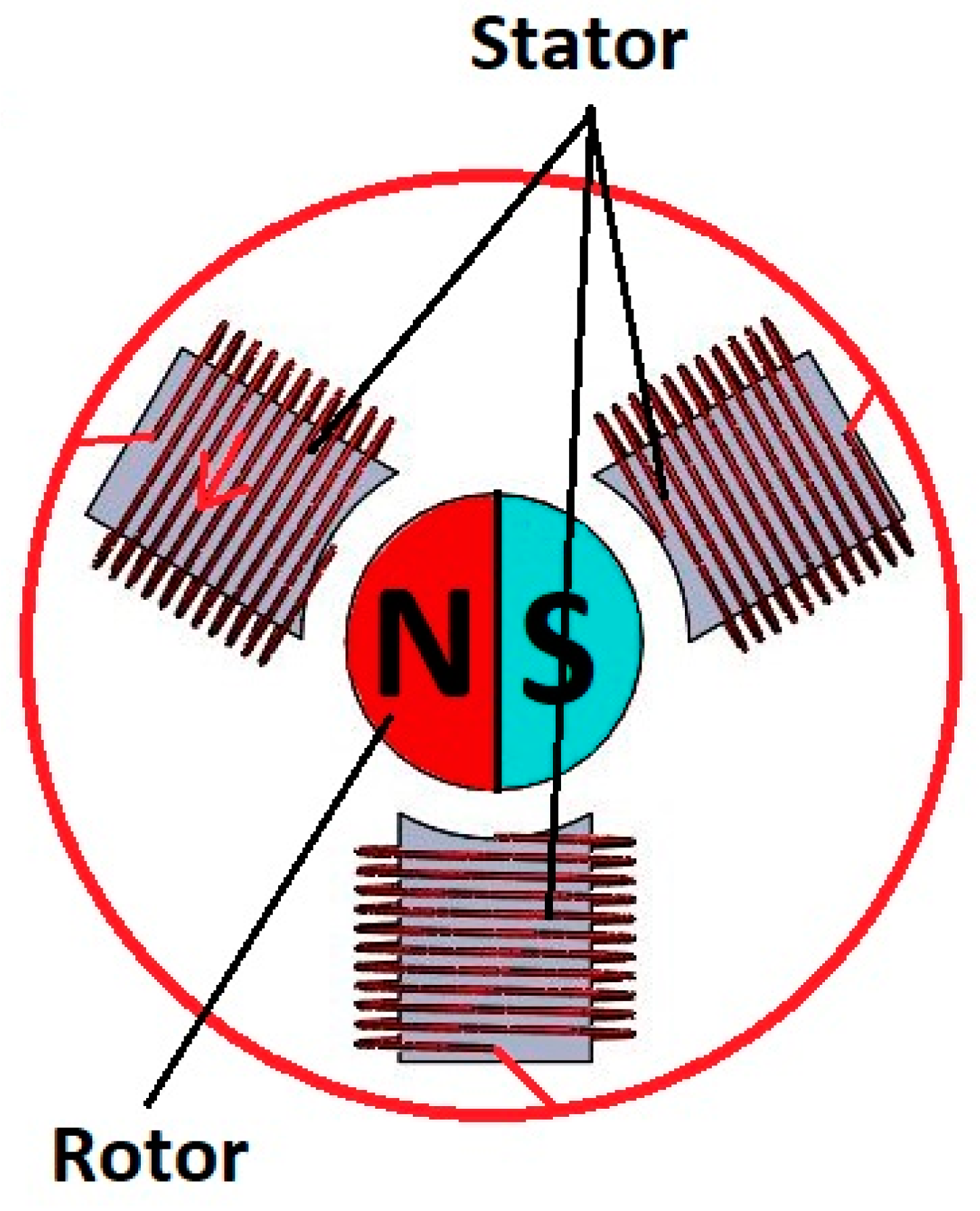
In brushless DC motors, permanent magnets are attached to the motor rotor, which is the only moving component. All other parts, including coils, are stationary, and, therefore, there is no need for metallic brushes. The current directly flows through the coils, generates forces applied to the rotor and causes the rotor to rotate (
Figure 5).
4.2. Stepper Motors
Stepper motors can provide slow and precise rotational movement in discrete steps. The working principle of the stepper motor is similar to that of the brushless DC motor, but the only moving part of this motor, the rotor, moves in an accurate and fixed angle increment in each step [
22].
Using a controller system, it sends electrical pulses to a driver. The driver controls the operation of the stepper motor. It sends proportional voltage or current to the motor, based on various phases in pulses. This causes polarity of the coils and finally leads to moving the rotor.
There are four types of stepper drives:
Wave drives or one-phase-on drives: The driver energizes one pole of the motor at a time by sending current to the corresponding coil. This pole attracts the rotor magnet and causes the rotor to rotate toward that pole. In the next step, the drive energizes the next pole and turns the previous pole off. The rotor moves toward the second pole, and the rotation continues.
Two-phase-on drives: These drives work with two poles turned on at a time, which attracts the rotor magnet and aligns it in the middle of the two poles. The driver turns on the next pair of poles in the next step and turns off the previous poles.
One/two phase-on drives or half-stepping: In this method, either one or two poles are energized by the driver at any specific time. The first pole is energized and attracts the rotor magnet. Then the second pole is turned on. When the rotor rotates toward the second pole, the driver turns off the first pole and gets ready to turn on the third pole.
Micro stepping: In this method, a sine-wave current is applied to the poles, and no pole is completely on or off during the rotation of the rotor.
4.3. Servo Motors
A servo motor consists of a DC motor, a set of gears, and a positional sensor or encoder. The sensor senses the actual speed or position of the motor shaft and, using a feedback controller, the drift from target position is corrected; therefore, very precise motion of the motor is provided [
23]. Gears can slow down the high speed of the DC motor and increase the motor torque.
Two types of servo motors are positional rotation servos and continuous rotation servos. Positional rotation servos are used in systems to provide a moderate precise positioning and rotation, ranging from 0 to 180 degrees. They cannot provide a continuous rotation or speed control. Continuous rotation servos can continuously rotate at varying controlled speeds.
4.4. Hydraulic System
The basic idea of a hydraulic system is to transmit force from one point to another one, using an incompressible and pressurized fluid. The simplest hydraulic system consists of a container filled by liquid and a piston in contact with the fluid. The pressure is applied on the fluid from one side and forces it against the piston. By transferring energy from liquid to piston, it moves, and the fluid energy is converted to mechanical energy for use. The hydraulic system’s main components are as follows [
24]:
Reservoir: The liquid is stored in reservoir, where heat is transferred into the hydraulic system, and air and moisture are removed from the liquid.
Hydraulic circuits: Fluid flows through the hydraulic circuit and is transported from one component of the hydraulic system to the other one. The pressure of the fluid is also controlled in the hydraulic circuit.
Hydraulic pumps: Hydraulic pumps force the fluid to flow from the reservoir into the hydraulic system.
Hydraulic motors: A hydraulic motor is a mechanical actuator which generates torque and rotary motion from the hydraulic pressure and flow of liquid.
Hydraulic cylinders: A hydraulic cylinder is a mechanical mechanism which creates linear motion by converting hydraulic fluid energy into a force, to move a piston in the cylinder.
Valves: Valves are used to start and stop the hydraulic system and direct the movement of the fluid. Electrical, mechanical, hydraulic and pneumatic methods can be used to actuate valves in the system.
4.5. Thermal Actuators
These actuators are devices that convert thermal energy into mechanical energy, using properties such as thermal expansion, phase change or transformation characteristics of shape memory alloys. There are three types of thermal actuators [
25]:
Thermostatic actuators: These actuators consist of two or more metals with different thermal expansion coefficients. When they are heated, they change their shape and produce force and stroke.
Wax actuators: These actuators can generate force and linear motion by changing volume with change of temperature, due to thermal expansion or phase transition. The wax is held in a container with a movable piston. When the temperature increases, the volume of the wax under the piston increases and produces linear motion by moving the piston.
Shape memory alloy actuators: The working principle of these actuators is based on an important characteristic of shape memory materials called shape memory effects [
26,
27]. If shape memory material deforms at the Martensite phase, an increase in material temperature can recover the original shape by transformation of material phase from Martensite to Austenite. This phenomenon is called shape memory effect. In shape memory alloy actuators, deformation under load and original shape recovery after change of temperature produces stroke and mechanical motion [
28].
5. Power Supply
As the name suggests, power supply provides electrical power that is transmitted to an electrical load. The power supply can be a separate electrical source to deliver appropriate voltage, current and frequency to the electromechanical device, or it can be embedded into the system that it powers. The standard electricity format in the form of alternating current (AC) can be supplied by AC power. When electronics require consistent voltage delivery, direct current (DC) powers are used.
6. Controller Memory
Any program that the software engineer develops needs memory to run the system. All memories are not alike, and they operate in different ways. Memory can be categorized into two basic memory classifications: Read-Only Memory (ROM) and Random-Access Memory (RAM) [
29]. The ROM is readable, but new information can never be written to it, while RAM can be used to store programs and temporary data. That means data can be written, erased and rewritten.
ROM is a Non-Volatile Memory. This type of memory can save data even if the power is turned off. ROM is programmed by its manufacturer, and its contents are permanent.
PROM is a type of programable ROM that can be programmed by a user only once. After it is programmed, data stored in PROM are not changeable or erasable.
EPROM is an erasable PROM. Ultraviolet light is used to erase EPROM. EEPROM, however, is erased electrically. An EEPROM can be programmed and reprogrammed 10,000 times.
As an example, the microcontroller on the Arduino board has 512 bytes of EEPROM. All Teensy boards also have built-in EEPROM, which enables the user to collect and store data and save settings. Each Teensy has a different amount of EEPROM. Teensy 3.2 [
3,
30] for example, has 2048 bytes of EEPROM available.
A special form of EEPROM is Flash memory or Flash storage. Flash memory is a reprogramming memory chip which uses normal PC voltage to erase data and reprogram the chip. Flash memory is a Non-Volatile Memory. The advantage of Flash memory over EEPROM is that it is faster to update. EEPROM erases its data one byte at a time, while Flash memory erases the whole data block at once (in a flash). For this reason, Flash memory is chosen for applications which require repeated data updating. Flash memory must be erased before it is reprogrammed.
7. Operating System
While many microcontrollers like Arduino [
2,
31] and Teensy can be embedded in electromechanical devices and work with or without an operating system, in complex systems, an operating system is necessary and plays a significant role in organizing, controlling and managing hardware and software. The tasks of the operating system are management of the processor, memory, device and storage, as well as applications and user interfaces [
32]. The core of the operating system is the kernel, and the connection between operating system and hardware is mediated by driver. Driver is a special program which translates data from the operating system and application programs to hardware electrical signals. This is a method of communication between high-level programming languages with hardware subsystems. While drivers provide a path to use hardware, Application Program Interfaces (APIs) provide a means for a software developer to use the operating system without understanding the CPU’s operations in detail. This means the software programmer only needs to use the API during program development for access to the operating system, but not the hardware. In fact, the operating system connected to the driver deals with hardware subsystems, not the programmer.
There are four types of operating systems [
33]:
Real-time operating systems (RTOS);
Single-user, single-task;
Single-user, multi-tasking;
Multi-user.
For use in industrial systems, RTOS have important application in systems that are time-critical, while needing little or no user–interface capability. RTOS is quick in responses, a feature which is the main difference of this system and General-Purpose Operating System (GPOS). The basic functions of an RTOS are scheduling, resource management, synchronization, communication precise timing and Input/Output (I/O) services.
8. System Components Interconnections and Communications
After all parts of the system, including the system’s mechanism, sensors, actuators and controllers, have been selected, these parts must communicate to send and receive data and do the designed and proposed tasks. There are several communication protocols for this purpose. Here we discuss three of them.
8.1. I2C Communication Protocol
The I2C bus stands for “Inter IC”. It is a serial communication protocol and bidirectional two-wire interface that uses one or multiple master controllers communicating with slave devices. Each slave device on the I2C bus has a unique device address, discriminating it from other devices on the same bus.
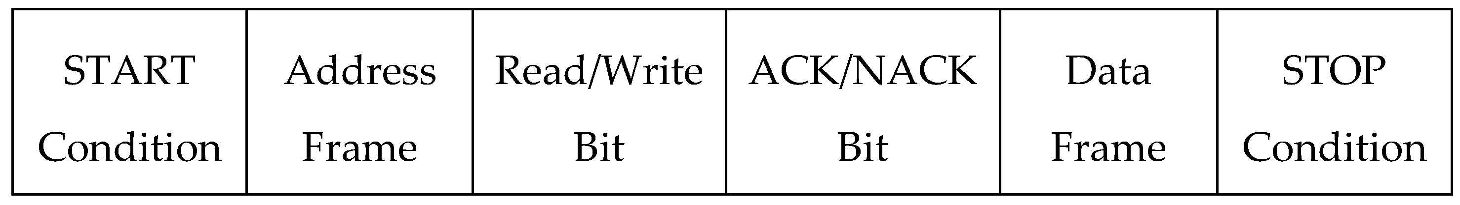
I2C uses two wires called Serial Clock (SCL) and Serial Data (SDA) lines [
34]. These lines are connected to VCC, and data are transmitted, bit by bit, along the SDA line, as messages. Each message has START and STOP conditions, slave address frame, data frame, Read/Write and ACK/NACK bits between data frames (
Figure 6). The address frame contains a 7- or 10-bit binary address unique to each slave device.
The START condition is defined by voltage at SDA line switching from high to low when SCL is at a high voltage level. Likewise, the STOP condition is when SDA voltage transition occurs from low to high and SCL is again high. Idle bus happens after the STOP condition when SDA and SCL lines are both at high voltage.
The general communication procedure for master accessing and sending data to the slave device is to send the START condition and address the slave, followed by the Read/Write bit set to 0 defining a write. Then, the master releases the SDA line. Each slave device connected to the master and I2C bus will compare the address received with their own address, to recognize if the addresses match. The addressed slave returns an ACK bit by changing the voltage at SDA line from high to low for one bit. Other slave devices leave the SDA line voltage high. The ACK-/NACK-related clock period (SCL) must be at its high phase, which is a NACK condition. Overall NACK condition may occur when the slave is unable to transmit or receive data, or data are not understandable, or the master has completed reading data from the slave. In this condition, the SDA line may remain at high voltage during ACK-/NACK-related SLC clock period. Now, the master sends the register address where information from the master will be written in the slave memory. Registers are parts of the memory of the slave which are used by the master device to read or write data from or to the slave device. For performing a task, a slave device is instructed by the master device by using written information into these registers. The slave device acknowledges receiving the register address that is up to 8 bits. At this point, the master transmits data to the slave and terminates data transfer by sending the STOP condition. The Most Significant Bit (MSB) of data is transferred first. After each data frame is sent successfully, the slave device returns another ACK bit to the master, to confirm that data receiving has been completed. Each data bit transfer is completed during one clock pulse of the SCL.
If the master is supposed to receive data from the slave, the procedure is very similar. The master sends the START condition and then follows that by addressing the slave, as well as sending the Read/Write bit equal to 0 again. Then it sends the requested register bit to request data from the slave. After acknowledgment of the register address by the slave, the master sends the second START condition, followed by the slave address and the last bit, which is the Read/Write bit set to 1, defining a read. After the slave acknowledges the read, the SDA bus is released by the master to get ready for the slave to transfer data. However, the master still continues sending clock pulses on the SLA line. At this time, data are transferred from slave to master, and the master acknowledges reception after it receives every Byte of data. Once all data are received by the master, it will send a NACK and terminate the procedure by sending a STOP condition. The Read/Write bit enables the slave to recognize if the master is going to write data to the slave or request data from it. The write bit is a low voltage level, while the read bit is high voltage.
8.2. CAN Communication Protocol
CAN stands for Controller Area Network, which is a multi-master serial communication bus with application mostly in the automobile industry, as well as building automation, medical instrumentation and equipment. In these applications, there are several electronic control units and subsystems controlling the functions of different parts of the entire system. In all these systems and subsystems, CAN allows interconnection between components to receive signals from sensors and control actuators, using controllers and microcontrollers in a safe, economical and convenient way. CAN is a two-wire bus which was invented to replace the original complex wiring harness connecting different parts of the system. The benefits of the CAN bus over conventional multi-wire looms are reduced weight and cost, and an increase in reliability.
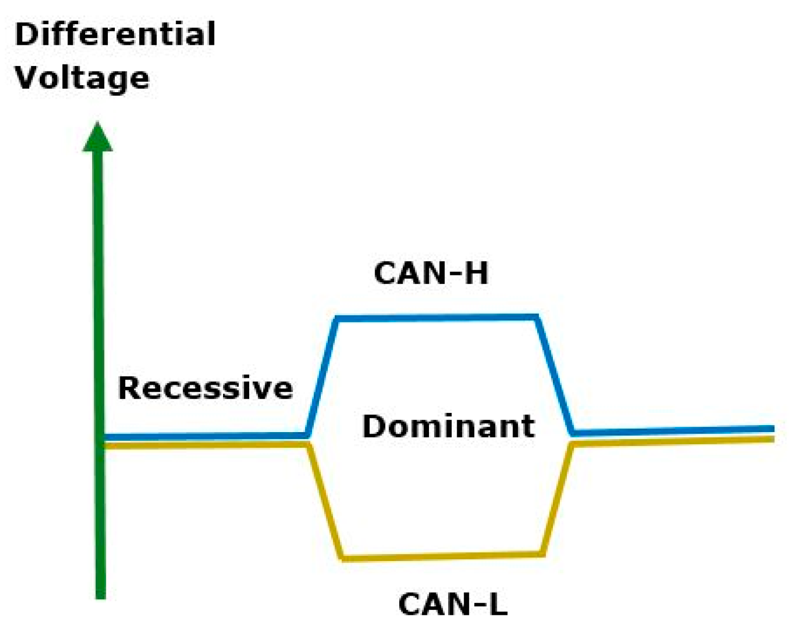
For communication, the CAN specifications use two logical states, which are called “Dominant” and “Recessive” [
35,
36]. The 0 bit is associated with the Dominant state, while 1 is associated with the Recessive state. If there is at least one node sending its output as a dominant to change the bus status, the differential voltage on CAN-H and CAN-L will increase to an amount larger than the minimum threshold. If the bus state is recessive, the differential voltage decreases to less than the mentioned threshold (
Figure 7).
There are four different types of messages transmitted on a CAN bus:
DATA Frame: This is the most common message frame that transmits data information from one sender to one or multiple receivers.
REMOTE Frame: This frame is transmitted on the bus to request data from another node; it does not contain data information.
ERROR Frame: When a node detects an error in a transmitted message, it sends an ERROR frame. The other nodes in the network will also send an ERROR message after they receive this frame.
OVERLOAD Frame: If a node becomes too busy, it sends the OVERLOAD message to request an extra time delay between DATA/REMOTE messages.
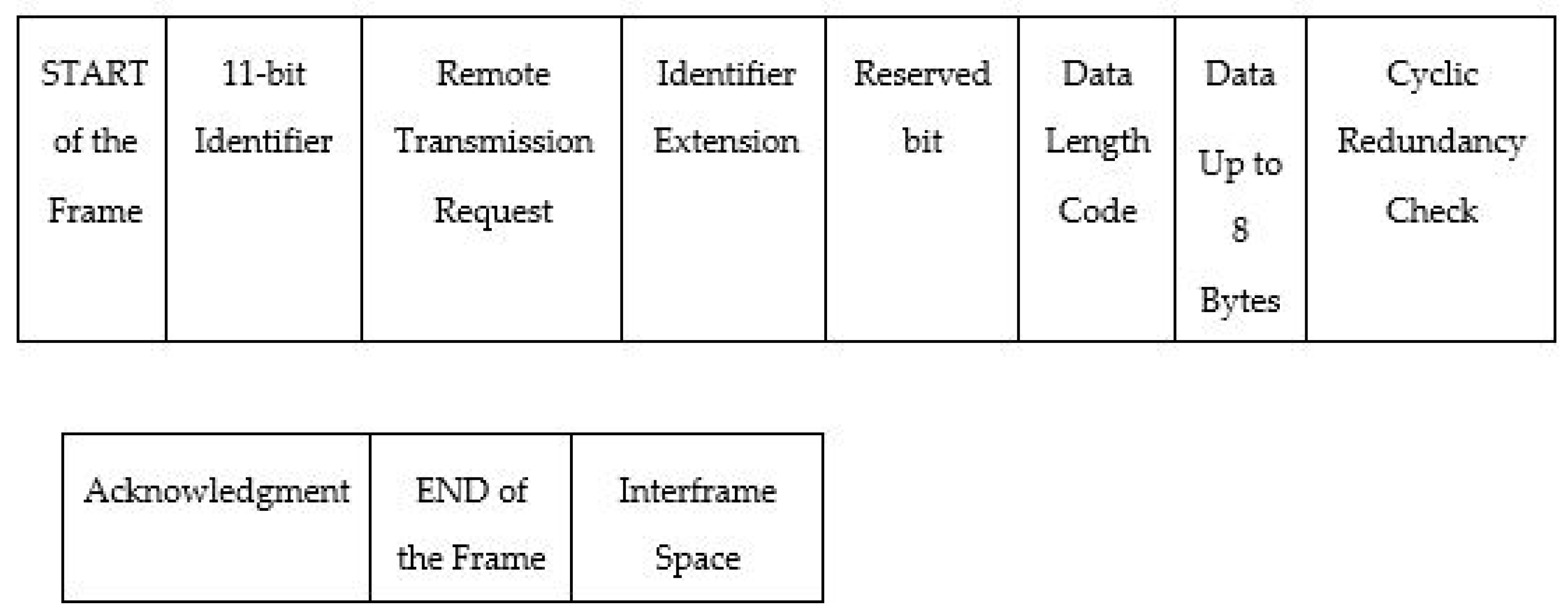
Each node on the bus is either a transmitter or receiver. The transmitter sends the message to all nodes. All nodes receive the message and determine if the message is relevant to them by applying message filtering and reception Masks to the received message identifier. The message identifier also shows the priority of the message on the CAN bus. The lower binary message identifier number is allocated to the message with higher priority. If two nodes simultaneously begin to transmit their messages, the node that sends the identifier bit as dominant will overwrite the recessive bit on the CAN bus and hold the bus to complete sending the message. The other node monitoring, both its own transmission and bus state, detects the bus state is unequal with the transmitted bit and therefore it halts transmission. This process is called arbitration.
Figure 8 shows the standard CAN DATA message.
Table 1 lists all parts of this message.
8.3. SPI Serial Communication
SPI stands for Serial Peripheral Interface, used for serial communication of a single microcontroller with peripheral ICs, like sensors, flash memories, analog-to-digital converters, etc. The SPI interface is usually four-wire [
37]. The four lines are Master Output/Slave Input (MOSI), Master Input/Slave Output (MISO), Clock (SCLK) and Slave Select/Chip Select (SS/CS). Unlike I2C and CAN communications, with data sending and receiving limited to a specific number of bits, any number of bits can be transferred continuously, without interruption, in SPI. Moreover, master and slaves can transmit data simultaneously.
Like I2C, SPI communicates by creating a master–slave relationship, but not through a complex slave addressing system. The connection between master and slave is through the SS/CS line, which is used by the master to select the slave device and send data to it.
For SPI communication, first the master sends the Clock signal, as well as Clock Polarity (CPOL) and Clock Phase (CPHA). Then it sends a logic “0” to SS/CS line to select the intended slave device. After that, data are sent and received by master and slave through MOSI and MISO lines. The SS/CS line is kept at high voltage when the SPI is idle. In SPI, there is no data reception acknowledgement and error checking.
CPOL and CPHA can be specified as “0” or “1”, to provide flexibility and four modes of communication between master and slave. When CPOL is “0”, it indicates that the clock signal related to idle state is low, and “1” for CPOL means the idle state is high. CPHA is related to data sampling. If the CPHA is “1”, data are sampled on the falling edge of the clock. When CPHA is “0”, data are sampled on the rising edge.
Multiple slaves can be connected to a single master by using several SS/CS pins (regular mode) or a single SS/CS pin (daisy-chain mode). In regular mode, each slave is connected to the master individually, using an SS/CS pin. The master selects the slave through the SS/CS line and communicates. In daisy-chain mode, one slave is connected to the master, and other slaves are connected to this slave and each other in a chain configuration. Data are sent directly from master to the first slave, and then data are propagated from each slave to the next one.
9. Conclusions
In this review, we discussed typical electromechanical systems and their important parts. We showed that a system consists of physical parts, including mechanisms, sensors, actuators and computing and analytical cores. We explained that, while these parts are joined and produce system hardware, the system software makes the communication between system components and internal and external computing systems possible. The system software consists of control algorithms and automation logics. Several programming languages, including embedded C and C++, can be used to program the analytical part of the system, to fulfil the controlling tasks. These programs may be used with a combination of an operating system, especially for complicated systems. For communication between different parts of the system, different communication protocols are available. We discussed CAN communication protocol, as well as SPI and I2C serial communication. In addition, we explained that every developed program or software needs to be stored in memory. We described different kinds of memories that are used for this purpose.
To develop a new system, the functions and outputs of the system, as well as environmental limits and constraints, are determined at the first step, and then the system’s hardware is designed and simulated. Many Computer Aided Design (CAD) software such as AutoCAD, SolidWorks and CATIA are available to visualize and simulate the system hardware. Sensing and motion-generating parts are designed or purchased from the marked. Programable and computing parts, as well as components communication methods, are selected. The system is assembled and programmed. It must be tested before it becomes available in the market for the user.


