Article

High-Precision Control of a Piezo-Driven Nanopositioner Using Fuzzy Logic Controllers †

by
Mohammed Altaher
1 and
Sumeet S. Aphale
2,*
1
School of Engineering, University of Aberdeen, Aberdeen AB24 3FX, UK
2
Centre for Applied Dynamics Research, School of Engineering, University of Aberdeen, Aberdeen AB24 3FX, UK
*
Author to whom correspondence should be addressed.
This paper is an extended version of our paper published in the 2017 International Symposium on Computer Science and Intelligent Controls.
Computers 2018, 7(1), 10; https://doi.org/10.3390/computers7010010
Submission received: 18 December 2017 / Revised: 16 January 2018 / Accepted: 18 January 2018 / Published: 22 January 2018

Abstract

:
This paper presents single- and dual-loop fuzzy control schemes to precisely control the piezo-driven nanopositioner in the x- and y-axis directions. Various issues are associated with this control problem, such as low stability margin due to the sharp resonant peak, nonlinear dynamics, parameter uncertainty, etc. As such, damping controllers are often utilised to damp the mechanical resonance of the nanopositioners. The Integral Resonant Controller (IRC) is used in this paper as a damping controller to damp the mechanical resonance. A further inherent problem is the hysteresis phenomenon (disturbance), which leads to degrading the positioning performance (accuracy) of the piezo-driven stage. The common approach to treat this disturbance is to invoke tracking controllers in a closed-loop feedback scheme in conjunction with the damping controllers. The traditional approach uses the Integral Controller (I) or Proportional Integral (PI) as a tracking controller, whereas this paper introduces the Proportional and Integral (PI)-like Fuzzy Logic Controller (FLC) as a tracking controller. The effectiveness of the proposed control schemes over conventional schemes is confirmed through comparative simulation studies, and results are presented. The stability boundaries of the proposed control schemes are determined in the same way as with a conventional controller. Robustness against variations in the resonant frequency of the proposed control schemes is verified.

1. Introduction

Piezo-actuators used in the nanopositioning stage are able to transform the electrical signal into a large mechanical force (movement) and vice versa. The produced movement is fast and extremely accurate; as a result, the piezo-actuators are widely used in many nanopositioning applications [1,2]. Such applications involve microscopy, lithography, nanomanufacturing, and optics, all of which have been gaining popularity in the last few decades [3,4]. In order to stimulate the piezo-actuators, voltage is applied to the positioning stage using high-frequency waveforms. However, this comes at the expense of the inherent hysteresis nonlinear phenomenon and the residual vibration [5]. These problems are particularly noticeable when there is any sudden change in the voltage applied to the piezo-driven stage. The hysteresis induced by the piezo-actuators is amplitude-dependent, and this is problematic for fast positioning application and large range movement. The traditional approach uses the Proportional Integral (PI) or Integral (I) as a tracking controller to treat hysteresis nonlinearity. For several reasons, including hysteresis disturbance and vibration problems, the conventional controllers are limited in their performance particularly when a high amplitude of the driven voltage is applied to the piezo-driven stage, even when damping controllers are used. The fuzzy system can facilitate a smooth transition from one control state to another, and this is done via characterisation of the fuzzy membership functions. Via its membership function, it can also handle vibration smother than a conventional controller. It is, therefore, necessary to develop a fuzzy logic controller capable of handling a nonlinear system. It must be explained that, in the case of the conventional controller, the integral action will create greater controller action than the fuzzy logic controller no matter how small the error, whereas the fuzzy logic controller can act negatively or positively to generate the required control action. The fuzzy can also predict via the trend (the change of error) to maintain the desired output. Therefore, the fuzzy logic controller will produce less overshoot and improve the dynamic characteristic of the system as it is using the trend as an indication to determine the controller action. It can act negatively or positively while maintaining the tracking performance.
More robust dynamic performance can be achieved using dual-loop control schemes, as opposed to traditional single-loop control schemes. This is because single-loop control schemes are less sensitive to nonlinearity such as hysteresis; this can be related to the fact that the single-loop control scheme makes small corrections in order to track perfectly [6]. Improving the dynamic characteristics of the piezo-driven stage is of significant importance in achieving accurate tracking performance in nanopositioning applications. One of the most important goals of the fuzzy logic controller is improving the dynamic characteristics of the system as compared with conventional controllers [7]. A comparative analysis of the fuzzy logic controller and its counterpart, the conventional controller, has proven that the fuzzy logic controller shows better dynamics behaviour [8]. Furthermore, the fuzzy logic controller can be used in conjunction with conventional control techniques to augment them and simplify their design [9]. In the case of nonlinear dynamics or uncertainty, the fuzzy logic controller is preferred over classical control techniques. The design of the fuzzy logic controller is uncomplicated and faster than conventional controllers; it is, in fact, easy to implement [10].
There are many types of damping controllers considered in the literature to treat the mechanical resonance of the piezo-driven stage [11,12]. For example, the Integral Resonant Controller (IRC) [13], the Polynomial Based Controller (PVPF) [14] and the Positive Position Feedback (PPF) [15]. This paper employs the fuzzy logic controller as a tracking controller in a single- and dual-loop control schemes in conjunction with the IRC.
The paper is organised as follows: Section 2 describes the background theory behind the system modelling and hysteresis nonlinearity. An explanation of the piezo-driven stage precise movement in the x- and the y-axis is detailed in Section 3 and the positioning tracking performance of the stage in the open-loop is also tested in this section. In Section 4, tracking controllers, including the conventional and the proposed fuzzy logic controller, are explored. Section 5 provides results to validate the enhanced performance of the proposed control schemes and results are presented under loading condition to prove the robustness of the proposed control schemes. Section 6 includes future work and Section 7 then concludes the paper.

2. System Modelling

In this section, the open-loop transfer-function based model for the x- and y-axis of the piezo-driven stage (nanopositioner) is presented. As the dynamics of the nano-axis has linear and nonlinear components, their modelling will thus be presented separately.

2.1. Linear Dynamics Model

The mechanical system of the piezo-driven stage is shown in Figure 1, which can be characterised and simplified by a spring-damper system. The axis of the piezo-driven stage is equipped with a capacitive sensor for position measurement. The system dynamics is regulated by the piezo-actuator force that moves the nanopositioning stage.
In a nanopositioning system, the transfer function of the plant is identified using the frequency response analysis. Using a subspace-based modelling technique as described in [16], the system is identified. The modelling methods such as neural networks or genetic algorithms [17,18] are typically used to model systems where all parameters are not directly identifiable. Typically, a simple second-order transfer function with a suitably low damping coefficient and the correct resonant frequency is sufficient to capture the dominant in-bandwidth dynamics of a nanopositioner’s axis. The transfer function is represented by a second-order model, as in the equation below:
G ( s ) = σ 2 s 2 + 2 ζ ω n s + ω n 2 ,
where ζ is the damping ratio, ω n is the natural frequency, and σ 2 is selected to manipulate the gain of the platform at 0 frequency. The transfer function of the platform is identified solely based on the first dominant mode (2738 Hz) for x- and y-axis, and given by:
X ( s ) = 4.828 × 10 8 s 2 + 918.793 s + 2.96 × 10 8 , Y ( s ) = 4.40152 × 10 8 s 2 + 963.528 s + 2.96 × 10 8 .
Figure 2a,b show that the modelled-based frequency response and the measurement-based frequency response, which are superimposed, are almost identical. It is clear from Figure 2a,b that the measures’ frequency response and the second-order model’s frequency response do not match exactly. As shown in Figure 1, the frequency responses are measured with the voltage amplifier as well as the capacitive displacement sensor in the loop. These components typically have first-order low-pass characteristics. It is ascertained that a fourth-order model (two complex conjugate poles for the resonant dynamics of the platform axis and one pole each for the cut-off of the low-pass characteristics of the amplifier and the sensor, respectively) accurately captures the dynamics displayed by the measured frequency response. However, to adhere to standard control design techniques, only the second-order resonant system model is utilised. As the input to the nanopositioner are typically staircase and triangular signals, which are made up of a combination of odd harmonics of the multiple, the slight mismatch in the model and the measured frequency response does not contribute to any significant performance degradation or instability issues.

2.2. Hysteresis Model

Nonlinear effects are usually unmodelled and tracking is enforced in order to minimise the effect of nonlinearities on the actual trace. Hysteresis is a dynamic characteristic present in many physical systems, such as piezo-actuators, and can lead to problems such as an increase in undesirable inaccuracy or oscillation and instability [19,20]. Therefore, any control strategy must be designed to accommodate uncertain time-varying nonlinear systems, as a result, the hysteresis is modelled using the Bouc Wen to represent the nonlinear relationship between the applied voltage and the displacement [21]. The selection of the Bouc Wen model in preference to other models is due to its simplicity and ability to capture the major hysteresis cycles. The equation of motion for the piezoelectric platform can be described using the Bouc Wen through nonlinear differential equations, as in Equation (3) [22]:
m x ¨ + b x ˙ + k x = k ( d u h ) , h ˙ = α d u ˙ β u ˙ h γ u ˙ h ,
where h represents the nonlinear relation between the lag force and the displacement. The parameters α , β and γ are identified in order to represent the hysteresis loop’s magnitude and shape, where α = 0.26 , β = 0.005 and γ = 0.00068 . The applied voltage can be denoted as u, and x as the displacement of the piezoelectric actuator; m, b, k and d represent the effective mass, damping coefficient, mechanical stiffness and effective piezoelectric coefficients ( d = 2 μ m per v o l t ), respectively. Open-loop investigation of the modelling of hysteresis is presented in Figure 3a,b, which is associated with the two axes of the nanopositioning platform (x and y).
The hysteresis is realised in MATLAB Simulink using a nonlinear differential equation representation of the Bouc Wen. The proposed hysteresis model is investigated by applying a 50 V peak amplitude sinusoidal signal of 10 Hz to the platform and the hysteresis cycle is thereby generated, as is clear in Figure 3a,b. A nonlinear rate-independent relationship is found to exist between the control voltages applied to the piezo-actuators and its displacements (10 μ m of lag). The following section aims to explain the principle operation of the piezo-driven stage in the open-loop.

3. The Piezo-Driven Stage Precise Movement

In this part of the paper, the principle operation of the nanopositioner is explained, along with its open-loop tracking performance.

3.1. Obtaining Raster Scan Trajectory

In nanopositioning applications, scanning in a raster pattern is required. The raster scan is achieved by applying a staircase signal to the y-axis and a triangular wave to the x-axis. The nanopositioning platform then moves forwards and backwards along the x-axis and it moves in a small step on the y-axis. The period of the step signal is the same as triangular in a synchronised pattern. It is important to note that the piezo-actuators used in nanopositioning applications are uni-polar actuators. This leads to the condition that only positive voltage can be applied to avoid depolarisation; as a result, bias is generally added. This allows the Alternating Current (AC) signals to be applied on top of the bias. Therefore, as can be seen from Figure 4a, the triangular signal has only a positive part mimicking a uni-polar condition and the period of the step signal is equivalent to the period of the triangular waveform. The proposed nanopositioning platform has a scanning range of 25 μ m in each axis and 2.5 μ m per 1 V sensor gain. In order to obtain a scanning range of 25 μ m × 25 μ m, a triangular waveform with 25 Hz and an amplitude of 62.5 V, a staircase with peak amplitude of 62.5 V and step changes of 2.5 μ m are selected to drive the platform. For simplicity and clarity reasons, the step change is larger than 1 μ m in order to cover the entire scanning range with 10 steps. The expected trajectory is plotted in Figure 4b.

3.2. Open-Loop Tracking Performance

As explained, a triangular wave with a fundamental frequency of 25 Hz is applied to drive the x-axis of the nanopositioner, and a synchronised staircase signal with fixed step changes is used to drive the y-axis. The open-loop tracking performance is performed using the MATLAB simulation and evaluated using reference tracking. It can be observed that tracking the triangular wave is nonlinear and oscillatory, as can be seen from Figure 5a. The triangular wave also deviates from the linearity in tracking its reference due to hysteresis nonlinearity of the piezo-actuators used in the nanopositioning platform. Mechanical vibration is also observed at the high-frequency components of the triangular wave. The staircase tracking is also nonlinear and oscillatory, particularly at the step changes where the system is highly susceptible to experience mechanical vibration, as is clear from Figure 5b. The mechanical vibration is observed in both the x- and y-axis of the platform due to the lightly damped mechanical resonance of the platform. To conclude, the open-loop tracking performance is unsatisfactory and therefore it is not suitable for precise control.
In the following session, the present and proposed control strategies are conducted to overcome these problems.

4. Control Schemes

Controllability of the nanopositioning platform is a challenging and difficult matter due to various problems associated with the platform; hence, a combination of different controllers is required. The initial approach to controlling the platform is to use a suitable damping controller for resonance, and a well-designed tracking controller. The damping controller used in this paper is the Integral Resonant Controller (IRC), and the tracking controllers are Integral (I) and Proportional and Integral (PI)-like Fuzzy Logic Controller (FLC). In this section, the traditional and proposed schemes to control the piezo-driven stage (nanopositioning platform) are explained.

4.1. Traditional Control Strategy

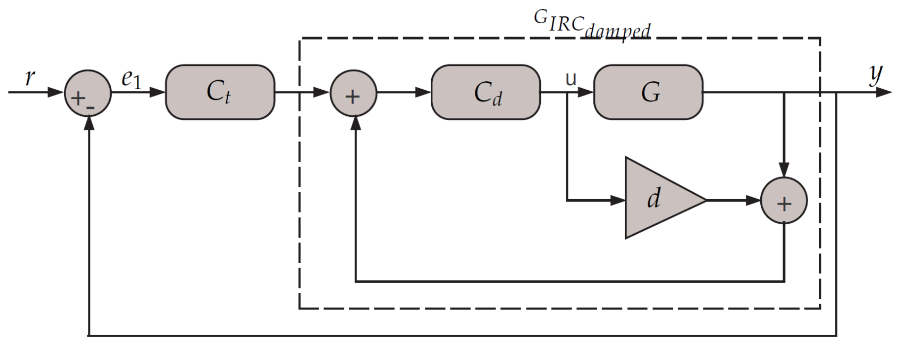
Considering the feedback configuration scheme in Figure 6, the figure illustrates the method by which the tracking and damping controllers are combined and used together. Controlling the nanopositioning platform is achieved through the use of single-loop feedback. In nanopositioning, the classical tracking controllers are generally either Proportional Integral (PI) or Integral (I). The damping controller that is used in this paper is the IRC. The conventional tracking controller that is used in conjunction with IRC is a simple integrator.
The IRC controller is an effective and successful scheme for vibration damping, and it is used in a wide range of nanopositioner applications [23]. This also has the desirable property of not exciting the higher frequency dynamics [24]. The transfer-function of tracking controller and the damped system are given by:
C t ( s ) = K t s , G I R C d a m p e d ( s ) = C d ( s ) × G ( s ) 1 C d ( s ) × ( G ( s ) + d ) , C d ( s ) = K d s .
The IRC can provide the appropriate damping to the system without providing tracking performance. The IRC scheme consists of a feed-through term and integral in the feedback, as is clear in 
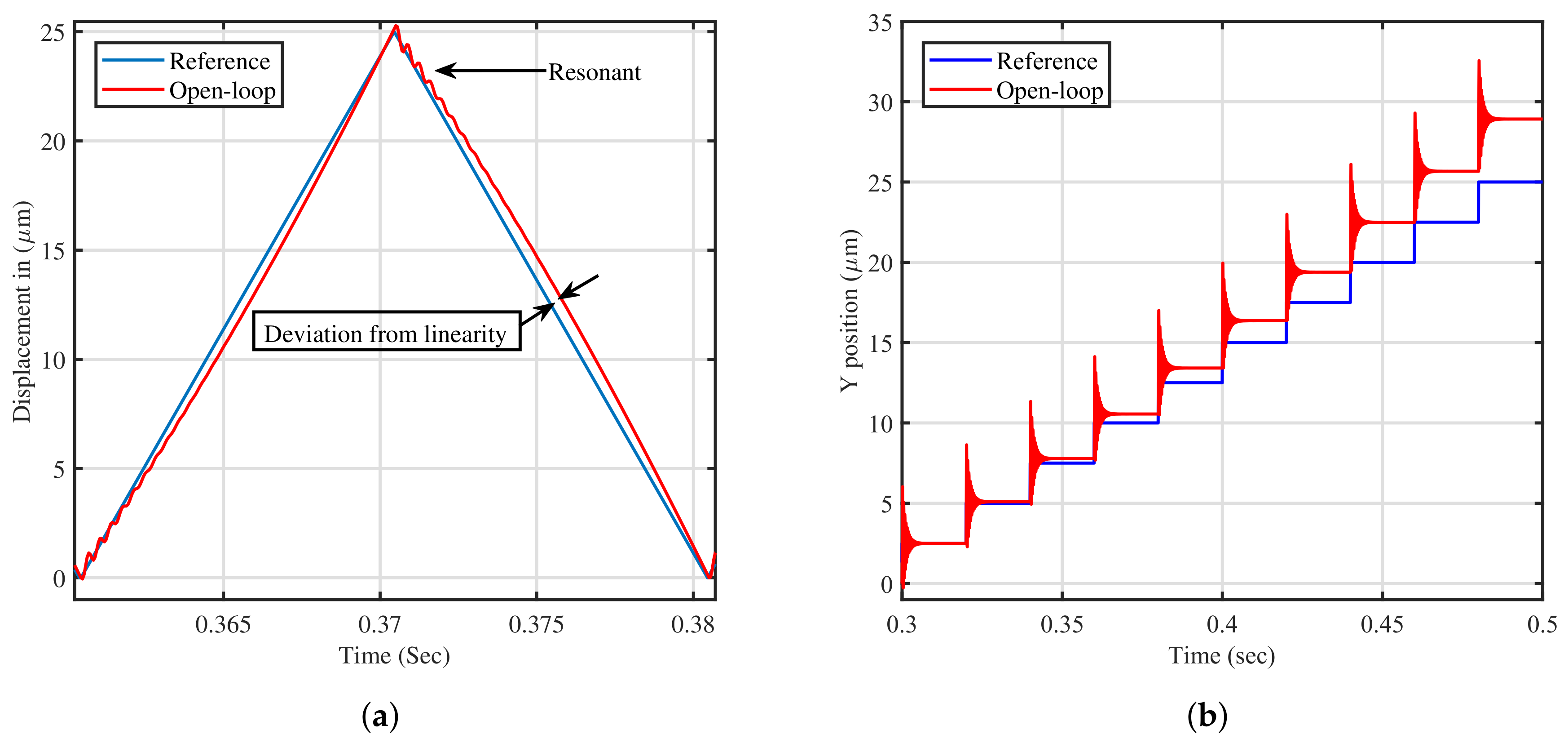
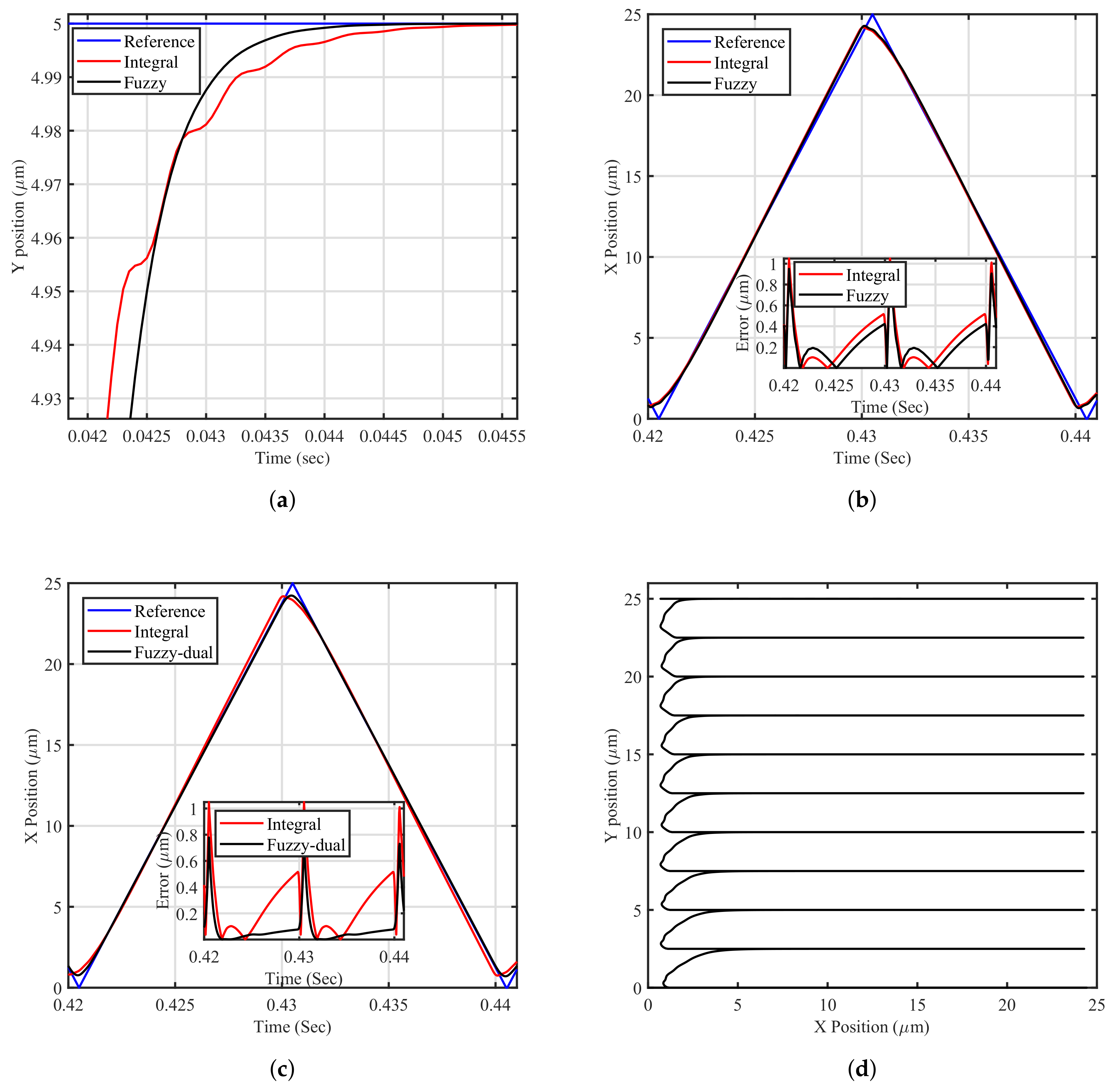
Figure 6. As will be illustrated in this paper, the traditional approach has clear limitations in tracking the reference signal. Tracking the staircase signal is challenging due to the resonant nature of the platform during sudden changes in the reference signal. Furthermore, tracking the triangular waveform is very difficult as it has high-frequency components and contains all the odd harmonics of its fundamental frequency [5]. In order to track triangular trajectories with zero-error, the double-integral action is warranted. Employing a double-integral action through the traditional scheme is not directly applicable due to the phase profile of the integral action and stability issues in the nanopositioning platform.

4.2. Proposed Control Strategy

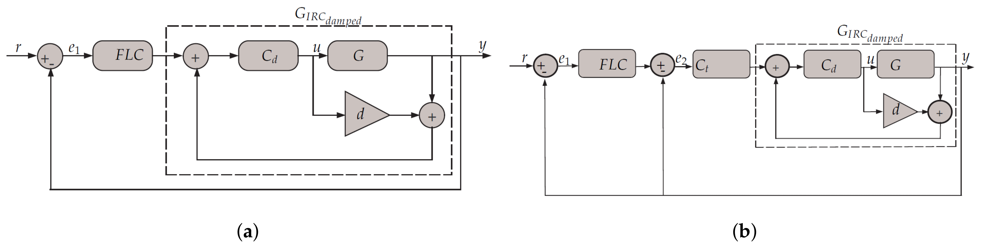
This work has thus far focused on linear controllers; however, nonlinear controllers have begun to be implemented in many studies. This research will investigate a nonlinear control strategy for better performance. The FLC will be used as a tracking controller to mimic the integral action, as will become clear in this section. The FLC is used in conjunction with the IRC instead of conventional (PI) or (I) tracking controllers in a single- and dual-loop fashion, as is clear in Figure 7a,b.
The control algorithm of the FLC in Figure 7a is mimicking the first-order integral action. As mentioned above, the closed-loop phase profile of the damped system does not furnish sufficient phase margin to allow for the implementation of a second-order integrator. Therefore, this paper proposes the implementation of a second tracking loop and it evaluates whether any improvement in positioning performance is achievable, as is clear from Figure 7b. It could be argued that the FLC as tracking can be used in the inner-loop feedback. Use of this in the inner-loop, however, has yet to be justified due to improvement in phase shift profile if it is used in the outer-loop. The overall control algorithm in Figure 7b consists of two first-order integral tracking controllers: C t and F L C 
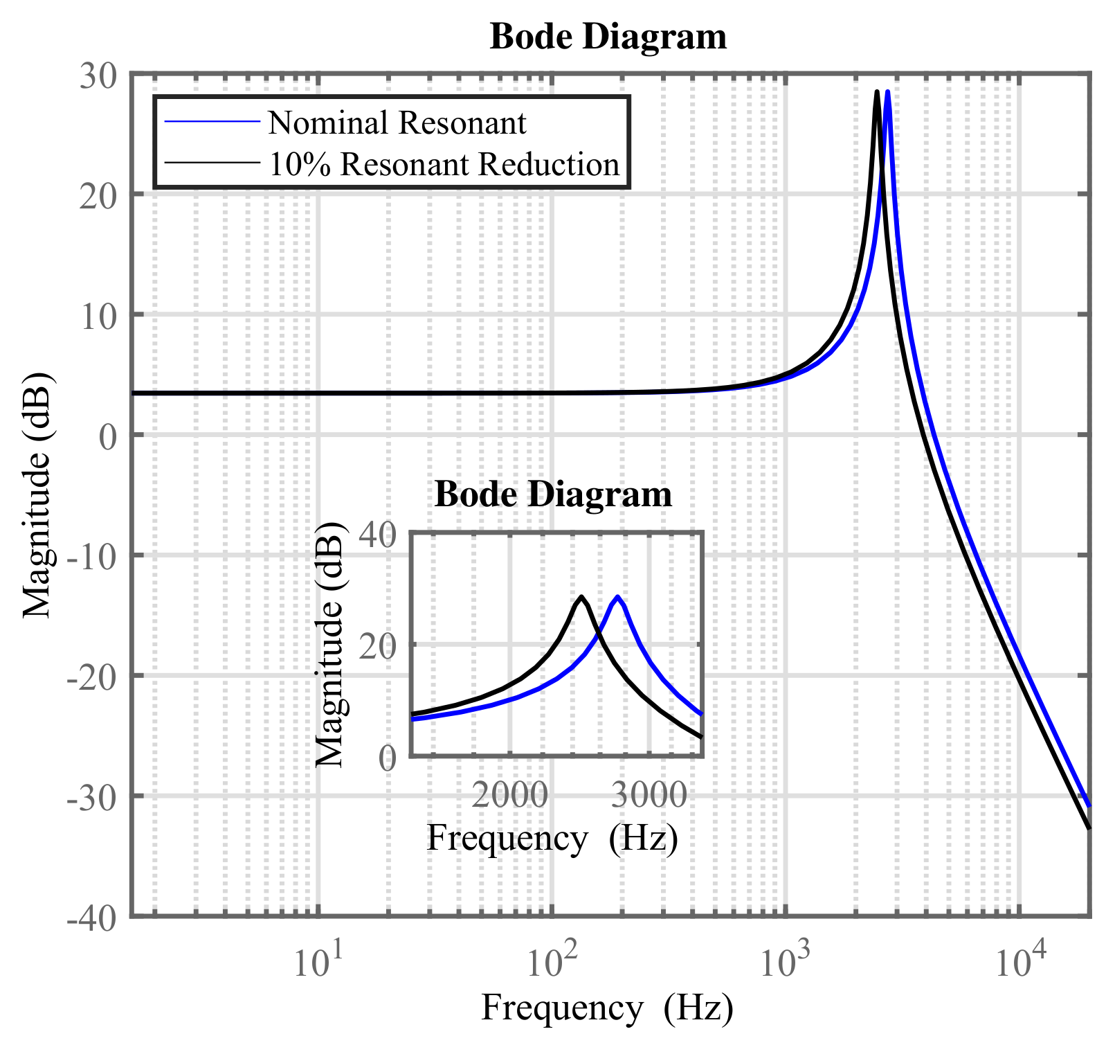
(mimicking). The FLC is preferred as opposed to the traditional controller in nanopositioning systems. This is due to the fact the system (piezo-driven stage) experiences the resonant mode inherently, and so the classical control will have clear limitations in damping the transient resonant mode, particularly given the fast response of the piezoelectric dynamics characteristics. The transient resonant mode will cause vibrations in terms of overshoot at any sudden change in the input signal, which will lead to inaccuracy in nanopositioning applications. The FLC can improve the dynamic characteristics in terms of reducing the overshoot. Below, the FLC components are described first, and the stability analysis of the proposed methods is then presented.

4.3. Fuzzy System Components

The fuzzy system is knowledge-based, and human experience can be incorporated into its design by mimicking expert knowledge via the fuzzy rules [25]. The fuzzy rules are linguistic rules characterised by and linked with conditional statements of ’If-then’. These sets of linguistic conditional statements represent the control situations. The behaviour of the FLC is highly restricted by its control table decisions, which contain the fuzzy rules. In 
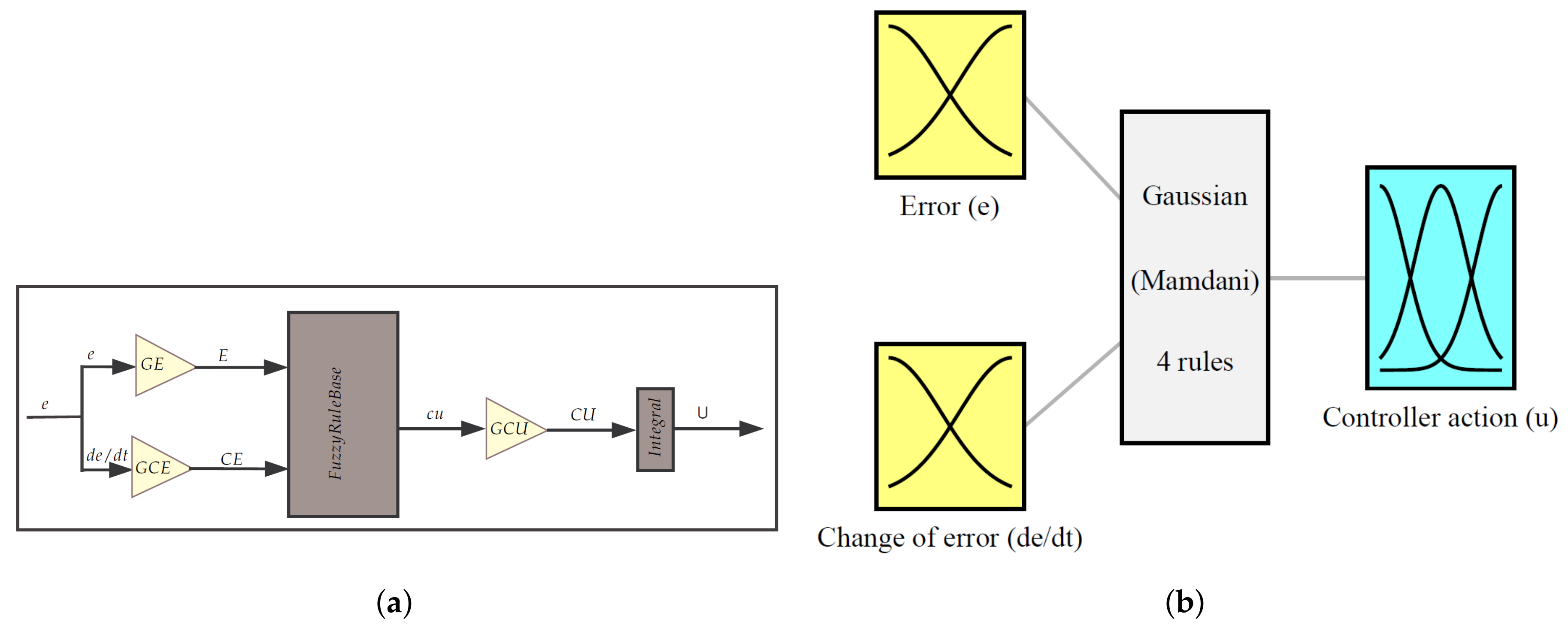
Figure 8a, a clear illustration of the FLC incremental gains’ distribution is presented. It can be seen from Figure 8b that the proposed controller is formed using four rules in order to make it simple.
The control input variables (crisp inputs) must be fuzzified before applying them to the control algorithm of the FLC. Normally, inputs to the FLC (state variables) include the error and change of error, as is clear from Figure 8b. In order for the controller to continuously account for the universe of discourse, a functional definition can be used to clarify the membership function of a fuzzy set. There are several types of membership function used in this regard, such as triangular, trapezoidal and bell-shaped functions. These membership functions are the most popular types of many engineering applications [26].
A Gaussian wave is used in this design, as can be seen in Figure 8. The proposed membership function is a plot of the function μ versus e ( t ) , where the horizontal x-axis represents the universe of discourse that covers the entire range of possible values for a chosen variable, and the vertical y-axis represents the membership value of the fuzzy set (certainty). In the fuzzy logic, membership is a matter of degree; it varies from 0 to 1 depending on the percentage allocated to each control situation. When implementing the membership function, the universe of discourse (crisp values) for the FLC is normalised within [−1,1] for the leftmost and rightmost, respectively. Gaussian membership functions are fuzzy membership functions that represent the linguistic terms; these functions are relatively popular in the fuzzy system literature and the output is very smooth. Hence, in this design, the Gaussian membership function is used to achieve a smoother control action and avoid an abrupt change in the controller action. The reason for this is that the Gaussian membership functions are smooth and non-zero at all points; therefore, no discontinuities in their derivatives are present.
The overlap of the membership is considered to be 25%, and the membership function at the overlap is equal to 0.5; this will keep the control action smooth in the case of a sudden change. The implementation of the membership function for the error and change of error is based on using two linguistic descriptions (N and P). Three linguistic descriptions are used to quantify the control action (N, Z and P), as is clear in the Table 1. It is important to note here that the membership functions for error, the rate of error and control action are selected to be the same (Gaussian).
In this research, the FLC is proposed as a tracking controller, not as a damping controller. Therefore, the fuzzy rules are designed based on the damped system dynamics using simulation. Using the simple logic, the control rules that make sense are set. The statement error is P, or N can represent the situation where the response of the system is at a significant distance from the setpoint. The statement error is Z, and this can represent the situation where the output response is the very close set point, or the system is reaching equilibrium and the error is null. The following rules are defined:
  • If the error is P and rate of error is P then the control action is P,
  • If the error is N and rate of error is N then the control action is N,
  • If the error is P and rate of error is N then the control action is Z,
  • If the error is N and rate of error is P then the control action is Z .
The Mamdani inference and centroid defuzzification are used in this work. Here, error (the difference between set point and actual process value) and change in error (the difference between current and past error) are the inputs to the fuzzy system. In the case of the fuzzy rule, the conditions can be satisfied (as opposed to crisp rules) smoothly; this has the desired effect of being able to interpolate between two rule conditions. This results in a smooth transition from one state to the other in the induced fuzzy control surface because of the Gaussian membership function.
With reference to Figure 8a, scaling factors are important parameters to tune into the FLC as they can scale the universe of discourse. Changing the scaling factors will affect the meaning of the linguistics that forms the basis of the fuzzy logic controller definition because it is redefining the horizontal axis. It can be concluded that scaling factors play a similar role to the gains of the conventional controller, as will become clear in the following section; they can also be a source of oscillation problems. Although the selection of suitable values of scaling factors is based on using the trial and error method, this is ruled out, and the relationship between scaling factors and their conventional counterpart is derived in the following section.

4.4. Stability Analysis of the Proposed FLC

In this paper, the rules are designed based on an analogy with the classical control system modelling. The dynamic characteristics of the proposed control system are considered as the fuzzy model, and the linguistic description of the dynamic characteristics can be used to obtain a set of fuzzy rules. The conventional PI control law is given by:
u ( t ) = K p e ( t ) + K i e ( t ) d t u ( t ) = K p [ e ( t ) + ( 1 T i ) e ( t ) d t ] ,
where e ( t ) is the error as function of time, K i is the integral gain, u ( t ) is the control output as function of time, K p is proportional gain and T i is an integral constant. By deriving the control law of the conventional controller, it can be obtained that:
u ˙ ( t ) = K p e ˙ ( t ) + K i e ( t ) .
The derivation of the control action means the trend and which can be referred to as Δ u. The derivation of the error can also be referred to as ▽e, and Equation (6) can thus be written as follows:
Δ u ( t ) = K p Δ e ( t ) + K i e ( t ) Δ u ( t ) = k p [ Δ e ( t ) + ( 1 T i ) e ( t ) ] .
An incremental controller adds a change in control signal Δ u to the current control signal. The incremental FLC is a type of fuzzy logic control systems where the controller output is not the control action “u”, but the controller output is the change of the control action Δ u. The FLC incremental Δ u is normalised and scaled as the linear non-invariant function of normalised error and normalised change of error and can be expressed as follows:
Δ u ( t ) G C U = f ( G E × e ( t ) , G C E × Δ e ( t ) ) ,
where GE, GCE and GCU are the scaling factors of error, change in error and incremental output variable, respectively. The function f is the input–output map of the normalised FLC incremental depends on many variables. From Equation (8), the FLC incremental Δ u can be written as follows:
Δ u ( t ) = G C E × G C U × [ Δ e ( t ) + G E G C E e ( t ) ] Δ u ( t ) = G C E × G C U × [ e ( t ) + G E G C E e ( t ) ] .
The relationship between the scaling factors for the FLC and the conventional controller is derived based on an analogy of the conventional controller by comparing Equations (7) with (9) as is clear below:
K p F L C ( F , D ) = G C E × G C U 1 T i = G E G C E K i F L C ( F , D ) = G C U G E ,
where F is an operation for fuzzification and D for defuzzification. From Equation (10), it is found that G C E multiplied by G C U is equivalent to K p . In this paper, the FLC is mimicking the integral action only and this can be done by setting the value of GCE to a small value. As noted from Equation (10), the proportional gain K p F L C ( F , D ) is dependent on GCE. Hence, as G C E < < G C U , the effect of the proportional gain is almost negligible. Therefore, the effect of the zero added by the FLC is tiny.
Referring to Figure 7a, the overall transfer function of the system can now be determined as follows:
Y ( s ) R ( s ) = K i F L C ( F , D ) C d G 1 d C d G C d + K i F L C ( F , D ) C d G .
Thus, the characteristics equation of the proposed single-loop fuzzy control strategy is given by:
s 4 d K d s 3 + ω p 2 s 2 ( d K d ω p 2 + K d σ 2 ) s + K i F L C ( F , D ) K d σ 2 = 0 .
As the value of ζ is usually small, it can be safely neglected in the overall analysis. The adequate feed-through term is independent of the parameters of the FLC and adequate value can be determined as in the following equation for the proposed single-loop fuzzy control strategy:
d K d ω p 2 K d σ 2 > 0 d < σ 2 ω p 2 .
In order to preserve stability and to increase the bandwidth, the values of the damping and tracking gains must obey the following quantities:
K d < 1 d ( ω p · ω p ω p 2 + σ 2 d ) , [ K i F L C ( F , D ) · K d ] < = ω p 4 4 σ 2 .
Therefore, tuning of the scaling factors (GCU and GE) is important in designing the FLC. Referring to Figure 7b, the overall transfer function of the system can now be determined as follows:
Y ( s ) R ( s ) = K i F L C ( F , D ) C t C d G K i F L C ( F , D ) C t C d G + 1 d C d G C d + C t C d G .
Thus, the characteristics equation of the proposed dual-loop fuzzy feedback scheme is given by:
s 5 d K d s 4 + ω p 2 s 3 ( d K d ω p 2 + K d σ 2 ) s 2 + K t K d σ 2 s + K i F L C ( F , D ) K t K d σ 2 = 0 .
Overall stability is examined for the proposed control scheme by applying the Routh–Hurwitz stability criterion. The characteristics equation of the proposed scheme is further analysed to determine the range of K t 1 , K i F L C ( F , D ) , K d and d required for closed-loop stability. For this characteristic polynomial to have all roots with negative real parts, the coefficients of all the “s” terms must be positive. Noting that K t 1 , K i F L C and K d are positive results in the following inequality to be a necessary condition for stability. Similar to the single-loop fuzzy, the adequate feed-through term is independent of the parameters of the FLC. The adequate feed-through term d, the damping gain K d and the tracking controller gains K t 1 and K t 2 are obtained. They are presented in Equations (17)–(19) to demonstrate that the relationship between the scaling factors for the FLC and the conventional controller is known. For simplicity purposes in this design, the normalisation factors are distinctively separated from the scaling factors:
d K d ω p 2 K d σ 2 > 0 d < σ 2 ω p 2 , K d < ω p 2 d + σ 2 + K t K i F L C ( F , D ) d K t d 2 ,
K t > K d d ω p 2 + σ 2 K d + ω p 2 K i F L C ( F , D ) K i F L C 2 ( F , D ) K d 2 d 2 K d d K d K i F L C ( F , D ) d ,
K i F L C ( F , D ) < K t ω p 2 + ( 2 K t ω p 2 + 4 K t 2 σ 2 + K t 2 + ω p 4 ) 2 K t .
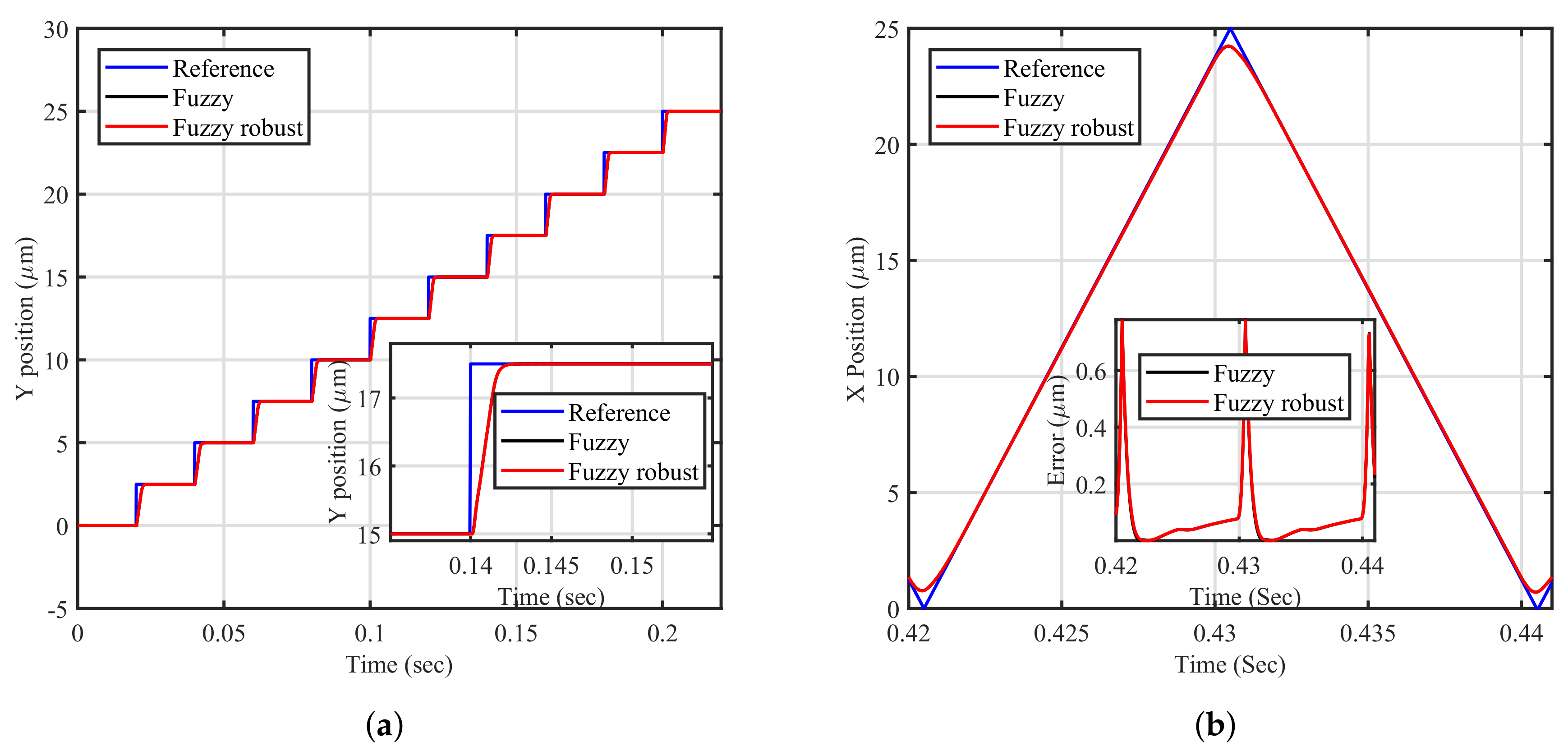
Although tuning the control action scaling factor alone can result in satisfactory behaviour, it is found that, in some cases, it can produce oscillation, whilst tuning the error scaling factor in conjunction with the control action scaling factor can result in less vibration and at the same time it can mimic the classical integral action. The selection of scaling factors is undertaken in a fashion to imitate the conventional integral controller. The main advantages of the proposed FLC are smooth control, removing the steady-state error, and better tracking performance, as will become clear in the following section. However, the limitation of the proposed FLC is the increase in the delay of the system using the dual-loop control strategy. Stability boundaries are determined using the trial and error methods to tune the scaling factors, in order to mimic the integral action that is a limitation of the proposed method.

5. Closed-Loop Tracking Results and Discussion

The simulation work is undertaken using the MATLAB Simulink environment. The sampling time is selected as 50 μ s due to the fast dynamic response of the piezoelectric. In order to test the tracking performance of the proposed control scheme, a staircase signal to drive the y-axis, and a corresponding frequency of 25 Hz triangle signal to drive the x-axis, are applied. The tracking performance of the closed-loop for both the x- and y-axis in single-loop schemes is plotted in Figure 9a,b. It is clear that the fuzzy single-loop tracking (proposed) achieves better performance in tracking the staircase signal as opposed to the single-loop integrator (traditional method). The proposed control scheme provides smoother controller action with no abrupt changes (a smooth transition), resulting in less vibration. The fuzzy single-loop reaches the reference quicker than the traditional method without experiencing vibration, despite experiencing a small delay throughout the dynamics transition. This is due to the use of Gaussian membership function as it is non-zero at all times; in addition, the FLC can handle nonlinearity and vibration due to its rules. Tracking of the traditional method single-loop integrator (traditional method) leads to abrupt changes in the controller action, no matter what tuning method is used, to achieve faster rising time and shorter settling time, the controller action is also not smooth and it causes overshoot.
The proposed method is further examined for the fairness of comparison, in Table 2. It is found that, by fixing the rising time the same for both controllers, the FLC can still show significant improvement in performance. The FLC is still capable of providing its smoother control action and can reduce overshoot from 15% to 8%. Additionally, it can also reduce the settling time. Since the nanopositioning platform experiences mechanical resonance noticeably at the step change, the overshoot is not preferred. Therefore, the FLC with its reduced overshoot is preferred for enforcing tracking in the y-axis.
From Figure 9b, it is seen that the proposed method shows a slight improvement in performance in comparison to the traditional method but is not substitutional. It is justified that tracking triangular waveform is more challenging as it contains all the major odd harmonics of its fundamental frequency. Tracking staircase signal is easier than tracking triangular waveform as it is closer to a sine wave and has fewer harmonics. The componential frequency response of the staircase-like signal is much lower than that of the triangular wave.
The proposed FLC has delivered improved tracking performance in the y-axis and a slight improvement in the x-axis in comparison to the conventional tracking method. Due to the requirement for accuracy in nanopositioning applications, the use of neither the traditional method nor the proposed single-loop fuzzy in the x-axis is satisfactory. As a result, the dual-loop fuzzy control scheme tracking is further examined to facilitate the implementation of the double integrator and the tracking performance is presented in Figure 9c. As can be seen from Figure 9c, a substantial improvement in the positioning error is obtained by tracking the triangular waveform of 25 Hz using the dual-loop fuzzy control scheme. It is clear that the traditional method deviates from linearity, whereas the FLC tracking remains linear for a significant duration of the desired trajectory.
Therefore, scanning in the x-axis using dual-loop fuzzy is preferred and the generated raster scan is created using a single-loop fuzzy to drive the y-axis and dual-loop fuzzy to drive the x-axis, as is clear in Figure 9d. The raster scan is smoother in the y-axis with less vibration, and it is more linear in the x-axis, as is evident from Figure 9a,b. It is noted that hysteresis of the piezo-actuators is amplitude-dependent; it exhibits highly nonlinear behaviour when a high amplitude of input voltage is applied. Since the applied voltage has a high amplitude, the classical control has clear limitations in its ability to track the reference perfectly.

Robustness

In this section, robustness to resonance frequency changes is evaluated. Robustness is a measure of the insensitivity to parameter changes in the closed-loop system performance [27]. In order for the closed-loop to be unresponsive to uncertainties, a reasonable stability margin is needed to cope with parameter changes. Piezo-driven stage systems are highly susceptible to experiencing variations in the resonant frequency [28]. Different payload masses are applied to the stage, resulting in changing the resonance frequencies of the structure. Therefore, the robustness of the proposed control schemes is tested for both the x- and y-axis for a 10% reduction in resonant frequency. The open-loop frequency response is plotted to mimic loading condition, as is shown in Figure 10.
In order to test the capability of the proposed control schemes to accommodate resonant frequency variation, the time-domain results are presented for the proposed control schemes in Figure 11a,b. It is clear that the proposed control schemes maintain superior tracking performance even under loading. There is no evidence that a reduction of 10% influences the tracking error with a proper selection of the scaling factors of the FLC.
It can be concluded that the performance under loading (mimicking) figures show that the tracking performance against the variations in the resonant frequency is satisfactory. In conclusion, the FLC is preferred as opposed to the conventional controller, for dealing with such an imprecise system and providing robust controller behaviour [29].

6. Future Work

The future work would involve the design of the FLC in a way that is not similar to the conventional way or even modelling the Bouc Wen using the fuzzy logic system.

7. Conclusions

The positioning performance of the nanopositioner is not acceptable if operated in the open-loop mode. The closed-loop performance of the traditional method is not showing noticeable improvement in performance, particularly in tracking higher frequency components of the x-axis. Therefore, the FLC in a closed-, single- and dual-loop fashion is introduced in this paper. The introduced FLC is formed using four simple rules. The staircase signal, which has a periodic increase, in amplitude is tracked better using the FLC than with the traditional method. The main contribution of this paper is to develop a dual-loop control scheme with FLC that can deliver a highly linear positioning performance with less error at the precision positioning stage. The developed FLC is synchronised analogously with a conventional controller and, based on its rules, the performance is improved. The stability criteria are derived in terms of the FLC scaling factors, for which they are examined in a similar fashion to the conventional method. According to the simulation results, the developed scheme has a verified effective solution to reduce tracking error, and the results providing a satisfactory performance in terms of the generated raster scan. Robustness of the FLC is examined to mimic loading conditions with no significant degradation of the tracking performance being observed.

Acknowledgments

The authors would like to thank Douglas Russell for the technical help and Andres San-Millan for data measurements. Financial support via the Elphinstone Research Scholarship, provided by the School of Engineering, University of Aberdeen, to fund Mohammed Altaher’s Ph.D. work is highly appreciated.

Author Contributions

Mr. Mohammed Altaher developed most of the theory and carried out all the simulations whose results are reported in this article. He was also the lead author for this article. Sumeet S. Aphale formulated the problem and set up the nanopositioning system. He provided guidance during the simulations as well as the final results analysis presented here. Additionally, he contributed to fine-tuning several sections of this article.

Conflicts of Interest

The authors declare no conflict of interest.

References

  1. Spanner, K.; Koc, B. Piezoelectric motors, an overview. Actuators 2016, 5, 6. [Google Scholar] [CrossRef]
  2. Ivan, I.; Aljanaideh, O.; Agnus, J.; Lutz, P.; Rakotondrabe, M. Quasi-static displacement self-sensing measurement for a 2-DOF piezoelectric cantilevered actuator. IEEE Trans. Ind. Electron. 2017, 64, 6330–6337. [Google Scholar] [CrossRef]
  3. Maroufi, M.; Fowler, A.G.; Moheimani, S.O.R. MEMS for Nanopositioning: Design and Applications. J. Microelectromech. Syst. 2017, 26, 469–500. [Google Scholar] [CrossRef]
  4. Gorman, J.J. MEMS nanopositioners. In Nanopositioning Technologies; Springer: Berlin, Germany, 2016; pp. 295–324. [Google Scholar]
  5. Rana, M.; Pota, H.R.; Petersen, I.R. Improvement in the Imaging Performance of Atomic Force Microscopy: A Survey. IEEE Trans. Autom. Sci. Eng. 2017, 14, 1265–1285. [Google Scholar] [CrossRef]
  6. Goodwin, G.C.; Graebe, S.F.; Salgado, M.E. Control System Design; Prentice Hall: Upper Saddle River, NJ, USA, 2001. [Google Scholar]
  7. Pivoňka, P. Analysis and Design of Fuzzy PID Controller Based on Classical PID Controller Approach; Fuzzy Control; Springer: Berlin, Germany, 2000; pp. 186–199. [Google Scholar]
  8. Yang, L.; Li, J. Adaptive Fuzzy Sliding Mode Control for Nano-positioning of Piezoelectric Actuators. Int. J. Fuzzy Syst. 2017, 19, 238–246. [Google Scholar] [CrossRef]
  9. Craig, K. Fuzzy Logic and Fuzzy Control; Report; Rensselaer Polytechnic Institute: Troy, NY, USA, 2011. [Google Scholar]
  10. Payam, A.F.; Rahman, E.M.A.; Fathipour, M. Control of Atomic Force Microscope Based on the Fuzzy Theory; INTECH Open Access Publisher: London, UK, 2011. [Google Scholar]
  11. Fleming, A.J.; Leang, K.K. Design, Modeling and Control of Nanopositioning Systems; Springer: Berlin, Germany, 2014. [Google Scholar]
  12. Eielsen, A.A.; Vagia, M.; Gravdahl, J.T.; Pettersen, K.Y. Damping and tracking control schemes for nanopositioning. IEEE/ASME Trans. Mechatron. 2014, 19, 432–444. [Google Scholar] [CrossRef]
  13. Aphale, S.S.; Fleming, A.J.; Moheimani, S.O.R. Integral resonant control of collocated smart structures. Smart Mater. Struct. 2007, 16, 439. [Google Scholar] [CrossRef]
  14. Bhikkaji, B.; Ratnam, M.; Moheimani, S.O.R. PVPF control of piezoelectric tube scanners. Sens. Actuators A Phys. 2007, 135, 700–712. [Google Scholar] [CrossRef]
  15. Marinangeli, L.; Alijani, F.; HosseinNia, S.H. Fractional-order positive position feedback compensator for active vibration control of a smart composite plate. J. Sound Vib. 2018, 412, 1–16. [Google Scholar] [CrossRef]
  16. Aziz, M.H.R.; Mohd-Mokhtar, R. Performance measure of some subspace-based methods for closed-loop system identification. In Proceedings of the 2010 Second International Conference on IEEE Computational Intelligence, Modelling and Simulation (CIMSiM), Tuban, Indonesia, 28–30 September 2010; pp. 255–260. [Google Scholar]
  17. Cheng, L.; Liu, W.; Yang, C.; Huang, T.; Hou, Z.G.; Tan, M. A Neural-Network-Based Controller for Piezoelectric-Actuated Stick–Slip Devices. IEEE Trans. Ind. Electron. 2018, 65, 2598–2607. [Google Scholar] [CrossRef]
  18. Lin, C.J.; Lin, P.T. Particle swarm optimization based feedforward controller for a XY PZT positioning stage. Mechatronics 2012, 22, 614–628. [Google Scholar] [CrossRef]
  19. Zhou, J.; Wen, C. Adaptive Backstepping Control of Uncertain Systems: Nonsmooth Nonlinearities, Interactions or Time-Variations; Springer: Berlin, Germany, 2008. [Google Scholar]
  20. Janaideh, M.A.; Rakotondrabe, M.; Al-Darabsah, I.; Aljanaideh, O. Internal model-based feedback control design for inversion-free feedforward rate-dependent hysteresis compensation of piezoelectric cantilever actuator. Control Eng. Pract. 2018, 72, 29–41. [Google Scholar] [CrossRef]
  21. Xu, Q.; Tan, K.K. Advanced Control of Piezoelectic Micro-/Nano-Positioning Systems; Springer: Berlin, Germany, 2015. [Google Scholar]
  22. Rakotondrabe, M. Bouc-Wen modeling and inverse multiplicative structure to compensate hysteresis nonlinearity in piezoelectric actuators. IEEE Trans. Autom. Sci. Eng. 2011, 8, 428–431. [Google Scholar] [CrossRef] [Green Version]
  23. Teo, Y.R.; Russell, D.; Aphale, S.S.; Fleming, A.J. Optimal integral force feedback and structured PI tracking control: Application for objective lens positioner. Mechatronics 2014, 24, 701–711. [Google Scholar] [CrossRef] [Green Version]
  24. Yong, Y.K.; Aphale, S.S.; Moheimani, S.O.R. Design, identification, and control of a flexure-based XY stage for fast nanoscale positioning. IEEE Trans. Nanotechnol. 2009, 8, 46–54. [Google Scholar] [CrossRef]
  25. Díaz-Cortés, M.A.; Cuevas, E.; Gálvez, J.; Camarena, O. A new metaheuristic optimization methodology based on fuzzy logic. Appl. Soft Comput. 2017, 61, 549–569. [Google Scholar] [CrossRef]
  26. Hitam, M.S. Design and Implementation of Fuzzy Control for Industrial Robot; INTECH Open Access Publisher: London, UK, 2006. [Google Scholar]
  27. Das, S.K.; Pota, H.R.; Petersen, I.R. A MIMO double resonant controller design for nanopositioners. IEEE Trans. Nanotechnol. 2015, 14, 224–237. [Google Scholar] [CrossRef]
  28. Habibullah, H.; Pota, H.; Petersen, I. A Novel Application of Minimax LQG Control Technique for High-speed Spiral Imaging. Asian J. Control 2018. [Google Scholar] [CrossRef]
  29. Reznik, L. Fuzzy Controllers Handbook: How to Design Them, How They Work; Elsevier: Newnes, Australia, 1997. [Google Scholar]
Figure 1. A piezo-stack actuated two-axis nanopositioner.
Computers 07 00010 g001
Figure 2. Comparison between the measured magnitude response and modelled of the system in the open-loop: (a) X-axis; (b) Y-axis.
Computers 07 00010 g002
Figure 3. Measured and modelled hysteresis loops show that the hysteresis model accurately captures the hysteresis of the piezo actuators: (a) X-axis; (b) Y-axis.
Computers 07 00010 g003
Figure 4. (a) The signals applied to the x-axis (triangular waveform 25 Hz) and a staircase to the y-axis; (b) Expected x y raster scan trajectory.
Computers 07 00010 g004
Figure 5. Tracking performance in the open-loop illustrates the deviation from linearity and mechanical vibration: (a) A triangle wave of 25 Hz for x-axis; (b) A staircase for y-axis.
Computers 07 00010 g005
Figure 6. Block diagrams for the traditional control scheme.
Computers 07 00010 g006
Figure 7. Block diagrams for the proposed control scheme: (a) Proposed single-loop fuzzy; (b) Proposed dual-loop fuzzy.
Computers 07 00010 g007
Figure 8. (a) Structure of incremental FLC shows scaling factors distribution; (b) Membership function, fuzzy rules and controller action of the proposed FLC.
Computers 07 00010 g008
Figure 9. Tracking performance of the closed-loop for: (a) A staircase reference for y-axis; (b) A triangular reference for x-axis using single-loop fuzzy; (c) A triangular (25 Hz) reference for x-axis using dual-loop fuzzy; (d) Raster scan trajectory for xy-axis using proposed dual- and single-loop control methods.
Computers 07 00010 g009
Figure 10. Open-loop magnitude response for resonant frequency changes for y-axis (mimicking loading).
Computers 07 00010 g010
Figure 11. A comparison of the tracking performance of the closed-loop under loading for: (a) a staircase for y-axis; (b) a triangular for x-axis.
Computers 07 00010 g011
Table 1. The linguistics of the proposed FLC.
AbbreviationNZP
LinguisticsNegativeZeroPositive
Table 2. Performance comparison between the fuzzy logic and conventional control scheme.
Control SpecificationFLCConventional Controller
Rising time1 ms1 ms
Overshoot/Oscillation8.59%15.19%
Peak time2.4 ms2.4 ms
Settling time6.3 ms6.7 ms

