A Mechanically-Adaptive Polymer Nanocomposite-Based Intracortical Probe and Package for Chronic Neural Recording


Abstract
1. Introduction
2. Materials and Methods
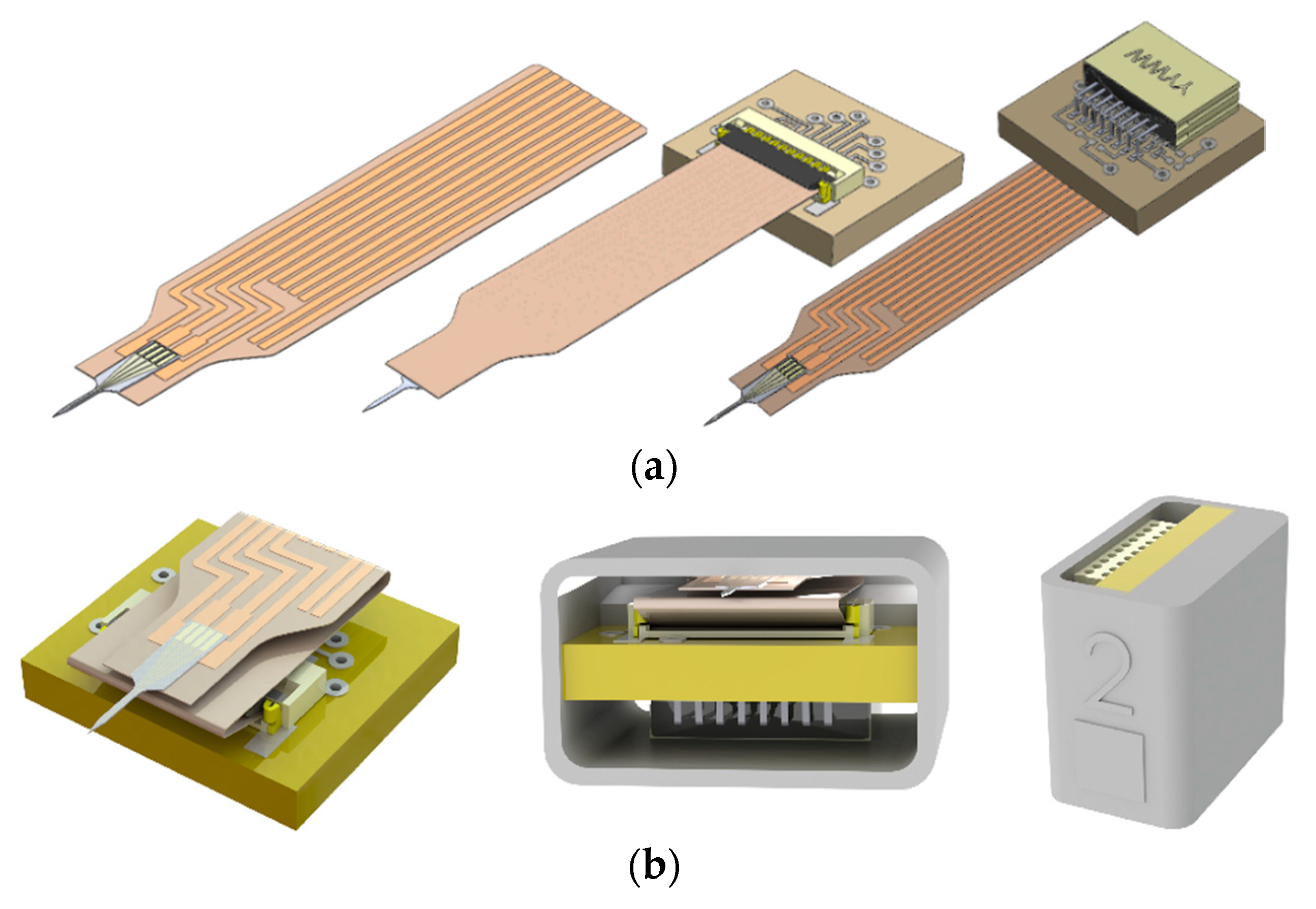
2.1. Design and Overview
2.2. Materials
2.2.1. PVAc-CNC
2.2.2. Parylene C
2.2.3. Au/Ti
2.3. Fabrication
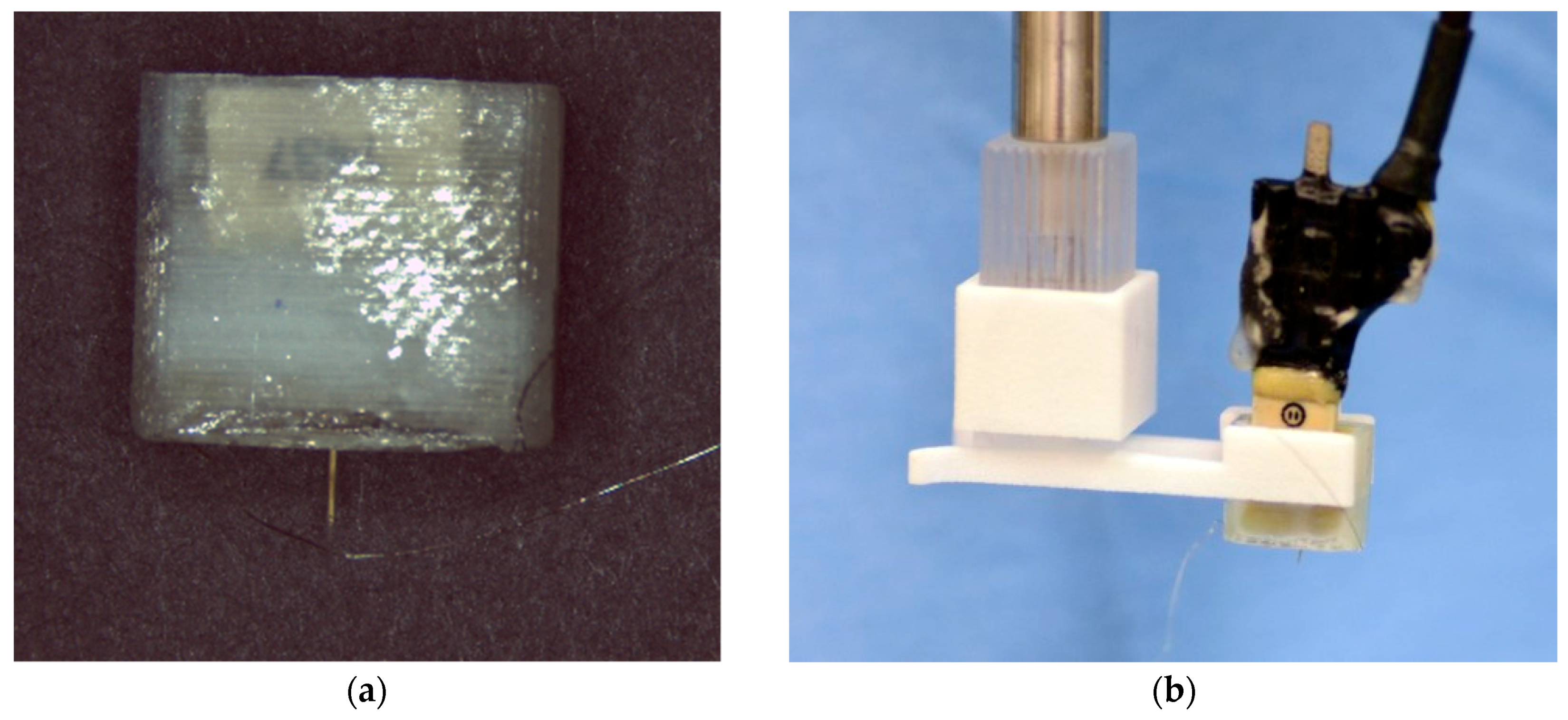
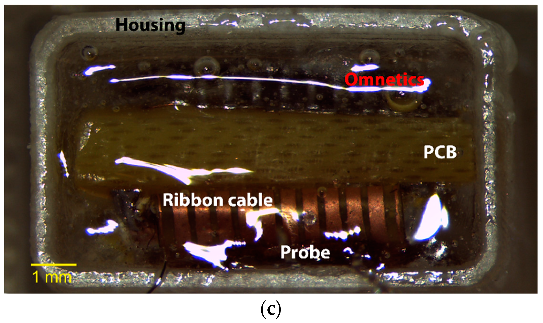
2.4. Packaging
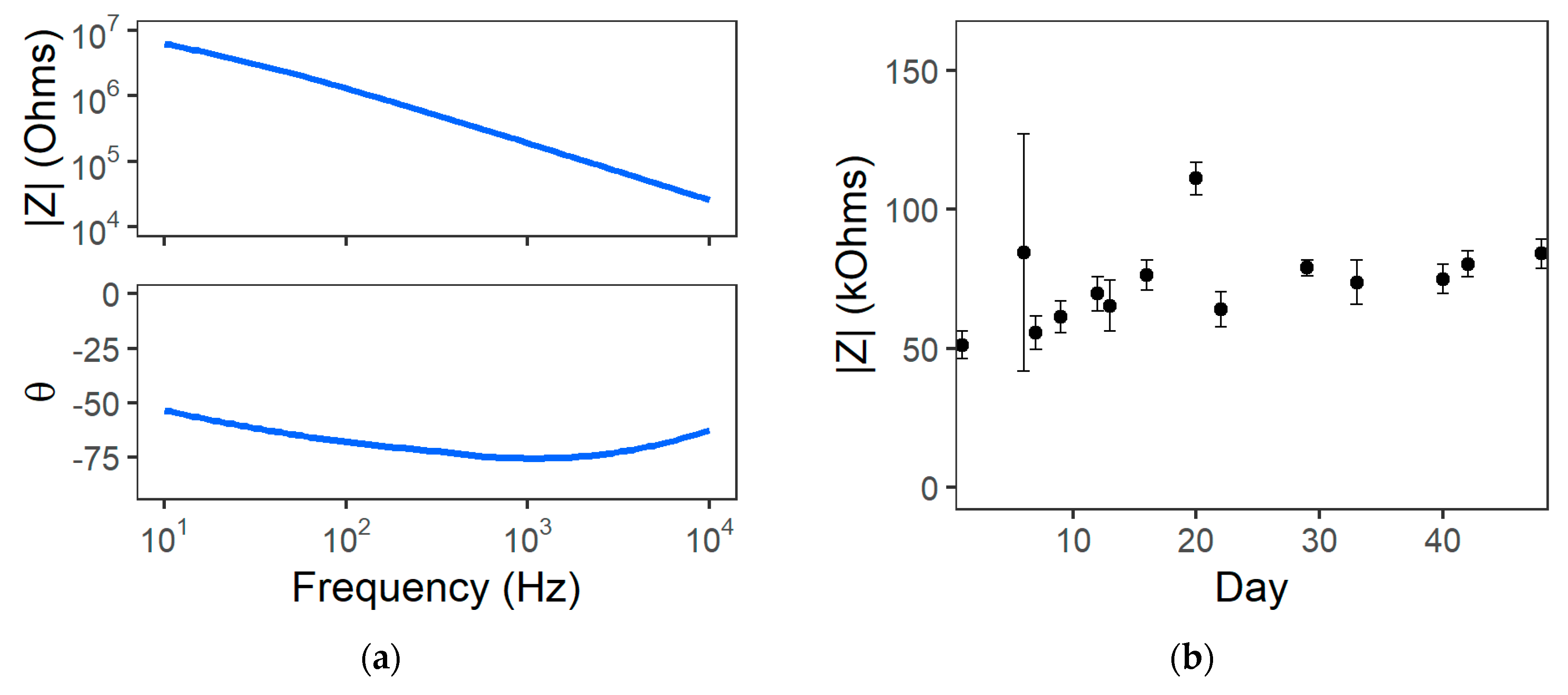
2.5. Benchtop Impedance Measurements
2.6. Chronic In Vivo Experiments
2.6.1. Surgical Procedure
2.6.2. Neural Recording and EIS Measurements
2.6.3. Neural Recording Data Analysis
3. Results and Discussion
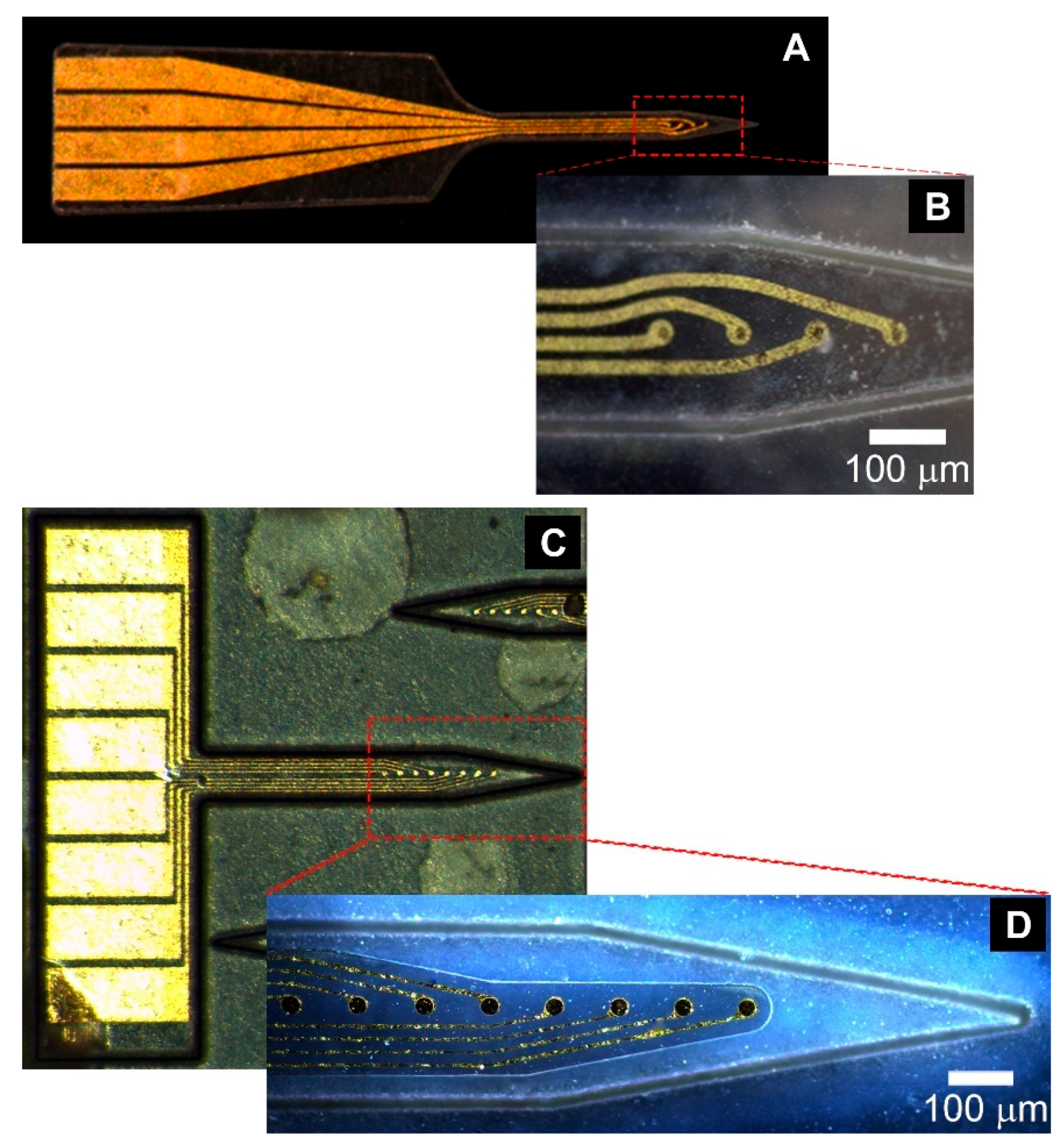
3.1. Device Fabrication
3.2. Probe Packaging
3.3. Benchtop Characterization
3.4. Chronic Implant Experiments
3.4.1. Surgery/Insertion
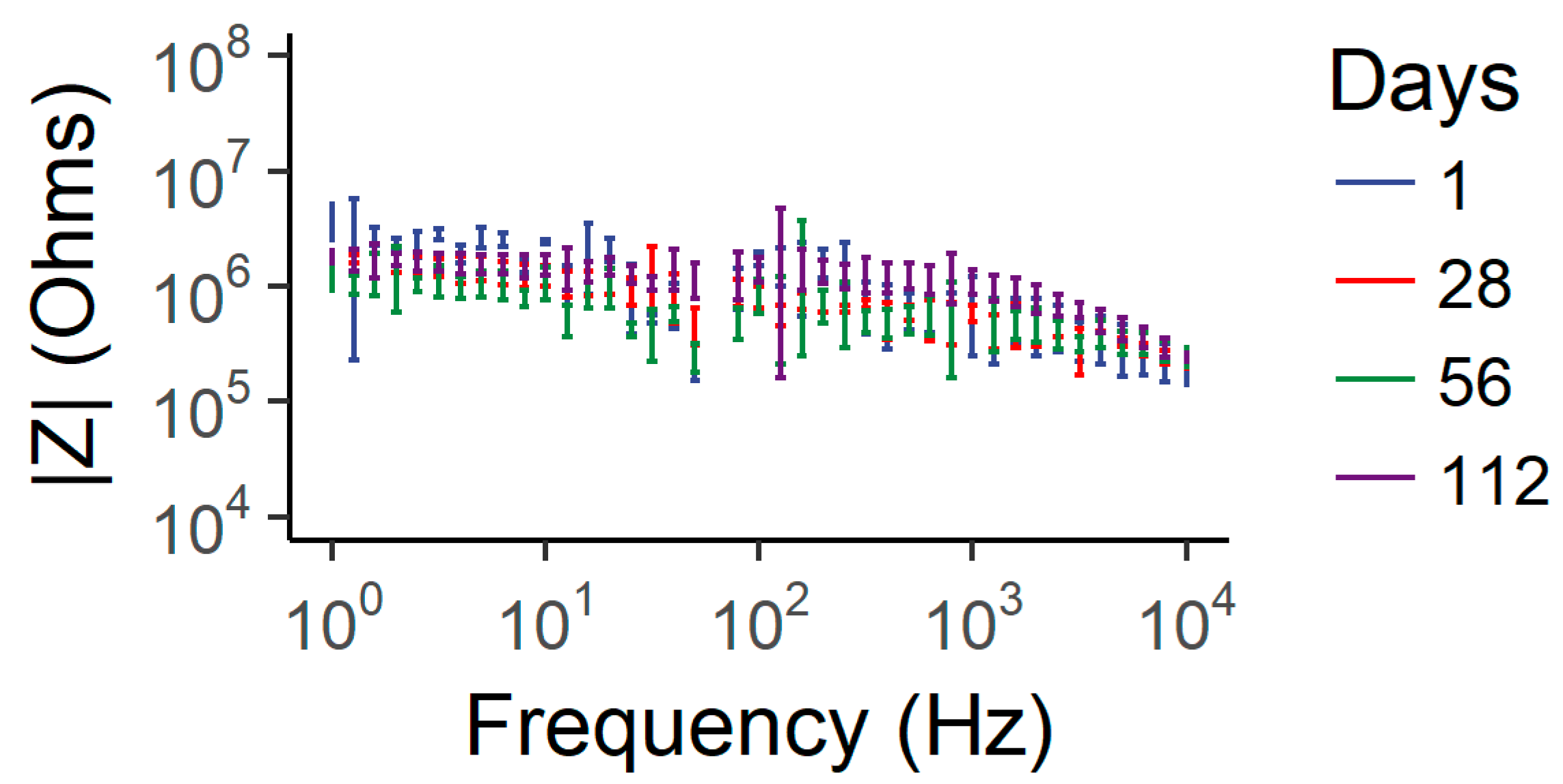
3.4.2. Electrochemical Impedance Spectroscopy
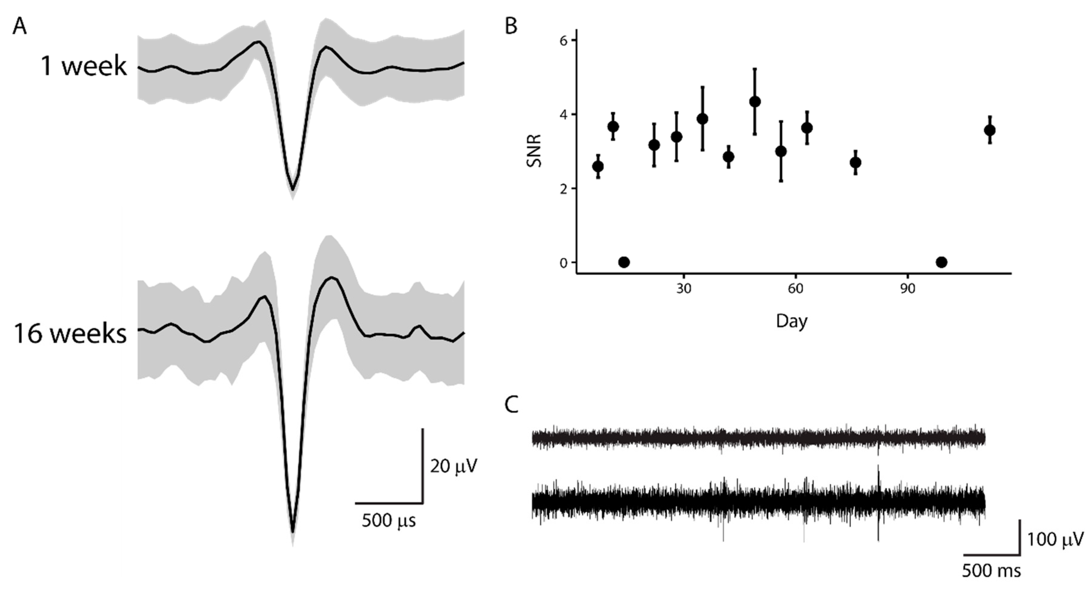
3.4.3. Chronic Neural Recording
4. Conclusions
Author Contributions
Funding
Acknowledgments
Conflicts of Interest
References
- Flesher, S.N.; Collinger, J.L.; Foldes, S.T.; Weiss, J.M.; Downey, J.E.; Tyler-Kabara, E.C.; Bensmaia, S.J.; Schwartz, A.B.; Boninger, M.L.; Gaunt, R.A. Intracortical microstimulation of human somatosensory cortex. Sci. Transl. Med. 2016. [Google Scholar] [CrossRef] [PubMed]
- Ferreira, N.R.; Ledo, A.; Laranjinha, J.; Gerhardt, G.A.; Barbosa, R.M. Simultaneous measurements of ascorbate and glutamate in vivo in the rat brain using carbon fiber nanocomposite sensors and microbiosensor arrays. Bioelectrochemistry 2018, 121, 142–150. [Google Scholar] [CrossRef] [PubMed]
- Clark, J.J.; Sandberg, S.G.; Wanat, M.J.; Gan, J.O.; Horne, E.A.; Hart, A.S.; Akers, C.A.; Parker, J.G.; Willuhn, I.; Martinez, V.; et al. Chronic microsensors for longitudinal, subsecond dopamine detection in behaving animals. Nat. Methods 2010, 7, 126–129. [Google Scholar] [CrossRef] [PubMed]
- Sim, J.Y.; Haney, M.P.; Park, S., II; McCall, J.G.; Jeong, J.-W. Microfluidic neural probes: In vivo tools for advancing neuroscience. Lab Chip 2017, 17, 1406–1435. [Google Scholar] [CrossRef] [PubMed]
- Seo, D.; Carmena, J.M.; Rabaey, J.M.; Maharbiz, M.M.; Alon, E. Model validation of untethered, ultrasonic neural dust motes for cortical recording. J. Neurosci. Methods 2015, 244, 114–122. [Google Scholar] [CrossRef] [PubMed]
- Aravanis, A.M.; Wang, L.P.; Zhang, F.; Meltzer, L.A.; Mogri, M.Z.; Schneider, M.B.; Deisseroth, K. An optical neural interface: In vivo control of rodent motor cortex with integrated fiberoptic and optogenetic technology. J. Neural Eng. 2007, 4, S143. [Google Scholar] [CrossRef] [PubMed]
- Ward, M.P.; Rajdev, P.; Ellison, C.; Irazoqui, P.P. Toward a comparison of microelectrodes for acute and chronic recordings. Brain Res. 2009, 1282, 183–200. [Google Scholar] [CrossRef] [PubMed]
- Prasad, A.; Xue, Q.-S.S.; Sankar, V.; Nishida, T.; Shaw, G.; Streit, W.J.; Sanchez, J.C. Comprehensive characterization and failure modes of tungsten microwire arrays in chronic neural implants. J. Neural Eng. 2012, 9, 56015. [Google Scholar] [CrossRef] [PubMed]
- Kozai, T.D.Y.; Catt, K.; Li, X.; Gugel, Z.V.; Olafsson, V.T.; Vazquez, A.L.; Cui, X.T. Mechanical failure modes of chronically implanted planar silicon-based neural probes for laminar recording. Biomaterials 2015, 37, 25–39. [Google Scholar] [CrossRef] [PubMed]
- Potter-Baker, K.A.; Capadona, J.R. Reducing the “Stress”: Antioxidative Therapeutic and Material Approaches May Prevent Intracortical Microelectrode Failure. ACS Macro Lett. 2015, 4, 275–279. [Google Scholar] [CrossRef]
- Potter-Baker, K.A.; Stewart, W.G.; Tomaszewski, W.H.; Wong, C.T.; Meador, W.D.; Ziats, N.P.; Capadona, J.R. Implications of chronic daily anti-oxidant administration on the inflammatory response to intracortical microelectrodes. J. Neural Eng. 2015, 12, 046002. [Google Scholar] [CrossRef] [PubMed]
- Takmakov, P.; Ruda, K.; Scott Phillips, K.; Isayeva, I.S.; Krauthamer, V.; Welle, C.G. Rapid evaluation of the durability of cortical neural implants using accelerated aging with reactive oxygen species. J. Neural Eng. 2015, 12, 026003. [Google Scholar] [CrossRef] [PubMed]
- Polikov, V.S.; Tresco, P.A.; Reichert, W.M. Response of brain tissue to chronically implanted neural electrodes. J. Neurosci. Methods 2005, 148, 1–18. [Google Scholar] [CrossRef] [PubMed]
- Biran, R.; Martin, D.C.; Tresco, P.A. Neuronal cell loss accompanies the brain tissue response to chronically implanted silicon microelectrode arrays. Exp. Neurol. 2005, 195, 115–126. [Google Scholar] [CrossRef] [PubMed]
- Woolley, A.J.; Desai, H.A.; Otto, K.J. Chronic intracortical microelectrode arrays induce non-uniform, depth-related tissue responses. J. Neural Eng. 2013, 10, 026007. [Google Scholar] [CrossRef] [PubMed]
- Seymour, J.P.; Kipke, D.R. Neural probe design for reduced tissue encapsulation in CNS. Biomaterials 2007, 28, 3594–3607. [Google Scholar] [CrossRef] [PubMed]
- Kozai, T.D.Y.; Langhals, N.B.; Patel, P.R.; Deng, X.; Zhang, H.; Smith, K.L.; Lahann, J.; Kotov, N.A.; Kipke, D.R. Ultrasmall implantable composite microelectrodes with bioactive surfaces for chronic neural interfaces. Nat. Mater. 2012, 11, 1065–1073. [Google Scholar] [CrossRef] [PubMed]
- Ware, T.; Simon, D.; Arreaga-Salas, D.E.; Reeder, J.; Rennaker, R.; Keefer, E.W.; Voit, W. Fabrication of Responsive, Softening Neural Interfaces. Adv. Funct. Mater. 2012, 22, 3470–3479. [Google Scholar] [CrossRef]
- Takeuchi, S.; Ziegler, D.; Yoshida, Y.; Mabuchi, K.; Suzuki, T. Parylene flexible neural probes integrated with microfluidic channels. Lab Chip 2005, 5, 519–523. [Google Scholar] [CrossRef] [PubMed]
- Rousche, P.J.; Pellinen, D.S.; Pivin, D.P., Jr.; Williams, J.C.; Vetter, R.J.; Kirke, D.R.; Member, S.; Pivin, D.P.; Kipke, D.R.; Williams, J.C.; et al. Flexible polyimide-based intracortical electrode arrays with bioactive capability. IEEE Trans. Biomed. Eng. 2001, 48, 361–371. [Google Scholar] [CrossRef] [PubMed]
- Gilletti, A.; Muthuswamy, J. Brain micromotion around implants in the rodent somatosensory cortex. J. Neural Eng. 2006, 3, 189. [Google Scholar] [CrossRef] [PubMed]
- Sridharan, A.; Nguyen, J.K.; Capadona, J.R.; Muthuswamy, J. Compliant intracortical implants reduce strains and strain rates in brain tissue in vivo. J. Neural Eng. 2015, 12, 036002. [Google Scholar] [CrossRef] [PubMed]
- Spencer, K.C.; Sy, J.C.; Falcón-Banchs, R.; Cima, M.J. A three dimensional in vitro glial scar model to investigate the local strain effects from micromotion around neural implants. Lab Chip 2017, 17, 795–804. [Google Scholar] [CrossRef] [PubMed]
- Moshayedi, P.; Ng, G.; Kwok, J.C.F.; Yeo, G.S.H.; Bryant, C.E.; Fawcett, J.W.; Franze, K.; Guck, J. The relationship between glial cell mechanosensitivity and foreign body reactions in the central nervous system. Biomaterials 2014, 35, 3919–3925. [Google Scholar] [CrossRef] [PubMed]
- Khoshakhlagh, P.; Moore, M.J. Photoreactive interpenetrating network of hyaluronic acid and Puramatrix as a selectively tunable scaffold for neurite growth. Acta Biomater. 2015, 16, 23–34. [Google Scholar] [CrossRef] [PubMed]
- Nguyen, J.K.; Park, D.J.; Skousen, J.L.; Hess-Dunning, A.E.; Tyler, D.J.; Rowan, S.J.; Weder, C.; Capadona, J.R. Mechanically-compliant intracortical implants reduce the neuroinflammatory response. J. Neural Eng. 2014, 11, 056014. [Google Scholar] [CrossRef] [PubMed]
- Subbaroyan, J.; Martin, D.C.; Kipke, D.R. A finite-element model of the mechanical effects of implantable microelectrodes in the cerebral cortex. J. Neural Eng. 2005, 2, 103. [Google Scholar] [CrossRef] [PubMed]
- Xiang, Z.; Yen, S.-C.; Xue, N.; Sun, T.; Tsang, W.M.; Zhang, S.; Liao, L.-D.; Thakor, N.V.; Lee, C. Ultra-thin flexible polyimide neural probe embedded in a dissolvable maltose-coated microneedle. J. Micromech. Microeng. 2014, 24, 065015. [Google Scholar] [CrossRef]
- Fomani, A.A.; Mansour, R.R. Fabrication and characterization of the flexible neural microprobes with improved structural design. Sens. Actuators A Phys. 2011, 168, 233–241. [Google Scholar] [CrossRef]
- Sohal, H.S.; Jackson, A.; Jackson, R.; Clowry, G.J.; Vassilevski, K.; O’Neill, A.; Baker, S.N. The sinusoidal probe: A new approach to improve electrode longevity. Front. Neuroeng. 2014, 7, 10. [Google Scholar] [CrossRef] [PubMed]
- Hara, S.A.; Kim, B.J.; Kuo, J.T.W.; Lee, C.D.; Meng, E.; Pikov, V. Long-term stability of intracortical recordings using perforated and arrayed Parylene sheath electrodes. J. Neural Eng. 2016, 13, 066020. [Google Scholar] [CrossRef] [PubMed]
- Lecomte, A.; Castagnola, V.; Descamps, E.; Dahan, L.; Blatché, M.C.; Leclerc, E.; Bergaud, C. Silk and PEG as means to stiffen parylene probes for insertion in the brain: A comparison. J. Micromech. Microeng. 2015, 25, 125003. [Google Scholar] [CrossRef]
- Wu, F.; Tien, L.W.; Chen, F.; Berke, J.D.; Kaplan, D.L.; Yoon, E. Silk-backed structural optimization of high-density flexible intracortical neural probes. J. Microelectromech. Syst. 2015, 24, 62–69. [Google Scholar] [CrossRef]
- Altuna, A.; Gabriel, G.; Menéndez de la Prida, L.; Tijero, M.; Guimerá, A.; Berganzo, J.; Salido, R.; Villa, R.; Fernández, L.J. SU-8-based microneedles for in vitro neural applications. J. Micromech. Microeng. 2010, 20, 064014. [Google Scholar] [CrossRef]
- Tijero, M.; Gabriel, G.; Caro, J.; Altuna, A.; Hernández, R.; Villa, R.; Berganzo, J.; Blanco, F.J.; Salido, R.; Fernández, L.J. SU-8 microprobe with microelectrodes for monitoring electrical impedance in living tissues. Biosens. Bioelectron. 2009, 24, 2410–2416. [Google Scholar] [CrossRef] [PubMed]
- Luan, L.; Wei, X.; Zhao, Z.; Siegel, J.J.; Potnis, O.; Tuppen, C.A.; Lin, S.; Kazmi, S.; Fowler, R.A.; Holloway, S.; et al. Ultraflexible nanoelectronic probes form reliable, glial scar–free neural integration. Sci. Adv. 2017, 3, e1601966. [Google Scholar] [CrossRef] [PubMed]
- Altuna, A.; Berganzo, J.; Fernández, L.J. Polymer SU-8-Based Microprobes for Neural Recording and Drug Delivery. Front. Mater. 2015, 2, 47. [Google Scholar] [CrossRef]
- Rousche, P.J.; Normann, R.A. Chronic recording capability of the Utah Intracortical Electrode Array in cat sensory cortex. J. Neurosci. Methods 1998, 82, 1–15. [Google Scholar] [CrossRef]
- Hoogerwerf, A.C.; Wise, K.D. A three-dimensional microelectrode array for chronic neural recording. IEEE Trans. Biomed. Eng. 1994, 41, 1136–1146. [Google Scholar] [CrossRef] [PubMed]
- Harris, J.P.; Hess, A.E.; Rowan, S.J.; Weder, C.; Zorman, C.A.; Tyler, D.J.; Capadona, J.R. In vivo deployment of mechanically adaptive nanocomposites for intracortical microelectrodes. J. Neural Eng. 2011, 8, 46010. [Google Scholar] [CrossRef] [PubMed]
- Ware, T.; Simon, D.; Liu, C.; Musa, T.; Vasudevan, S.; Sloan, A.; Keefer, E.W.; Rennaker, R.L.; Voit, W. Thiol-ene/acrylate substrates for softening intracortical electrodes. J. Biomed. Mater. Res. Part B 2014, 102, 1–11. [Google Scholar] [CrossRef] [PubMed]
- Lo, M.; Wang, S.; Singh, S.; Damodaran, V.B.; Kaplan, H.M.; Kohn, J.; Shreiber, D.I.; Zahn, J.D. Coating flexible probes with an ultra fast degrading polymer to aid in tissue insertion. Biomed. Microdevices 2015, 17, 34. [Google Scholar] [CrossRef] [PubMed]
- Xu, H.; Hirschberg, A.W.; Scholten, K.; Berger, T.W.; Song, D.; Meng, E. Acute in vivo testing of a conformal polymer microelectrode array for multi-region hippocampal recordings. J. Neural Eng. 2018, 15. [Google Scholar] [CrossRef] [PubMed]
- Shoffstall, A.J.; Srinivasan, S.; Willis, M.; Stiller, A.M.; Ecker, M.; Voit, W.E.; Pancrazio, J.J.; Capadona, J.R. A Mosquito Inspired Strategy to Implant Microprobes into the Brain. Sci. Rep. 2018, 8, 122. [Google Scholar] [CrossRef] [PubMed]
- Capadona, J.R.; Shanmuganathan, K.; Tyler, D.J.; Rowan, S.J.; Weder, C. Stimuli-Responsive Polymer Nanocomposites Inspired by the Sea Cucumber Dermis. Science 2008, 319, 1370–1374. [Google Scholar] [CrossRef] [PubMed]
- Shanmuganathan, K.; Capadona, J.R.; Rowan, S.J.; Weder, C. Bio-inspired mechanically-adaptive nanocomposites derived from cotton cellulose whiskers. J. Mater. Chem. 2010, 20, 180. [Google Scholar] [CrossRef]
- Capadona, J.R.; Tyler, D.J.; Zorman, C.A.; Rowan, S.J.; Weder, C. Mechanically adaptive nanocomposites for neural interfacing. MRS Bull. 2012, 37, 581–589. [Google Scholar] [CrossRef]
- Shanmuganathan, K.; Capadona, J.R.; Rowan, S.J.; Weder, C. Biomimetic mechanically adaptive nanocomposites. Prog. Polym. Sci. 2010, 35, 212–222. [Google Scholar] [CrossRef]
- Hess, A.E.; Capadona, J.R.; Shanmuganathan, K.; Hsu, L.; Rowan, S.J.; Weder, C.; Tyler, D.J.; Zorman, C.A. Development of a stimuli-responsive polymer nanocomposite toward biologically optimized, MEMS-based neural probes. J. Micromech. Microeng. 2011, 21, 54009. [Google Scholar] [CrossRef]
- Hess, A.E.; Potter, K.A.; Tyler, D.J.; Zorman, C.A.; Capadona, J.R. Environmentally-controlled microtensile testing of mechanically-adaptive polymer nanocomposites for ex vivo characterization. J. Vis. Exp. 2013, e50078. [Google Scholar] [CrossRef] [PubMed]
- Hess-Dunning, A.E.; Tyler, D.J.; Harris, J.P.; Capadona, J.R.; Weder, C.; Rowan, S.J.; Zorman, C.A. Microscale Characterization of a Mechanically Adaptive Polymer Nanocomposite with Cotton-Derived Cellulose Nanocrystals for Implantable BioMEMS. J. Microelectromech. Syst. 2014, 23, 774–784. [Google Scholar] [CrossRef]
- Harris, J.P.; Capadona, J.R.; Miller, R.H.; Healy, B.C.; Shanmuganathan, K.; Rowan, S.J.; Weder, C.; Tyler, D.J. Mechanically adaptive intracortical implants improve the proximity of neuronal cell bodies. J. Neural Eng. 2011, 8, 066011. [Google Scholar] [CrossRef] [PubMed]
- Arreaga-Salas, D.E.; Avendaño-Bolívar, A.; Simon, D.; Reit, R.; Garcia-Sandoval, A.; Rennaker, R.L.; Voit, W. Integration of High-Charge-Injection-Capacity Electrodes onto Polymer Softening Neural Interfaces. ACS Appl. Mater. Interfaces 2015, 7, 26614–26623. [Google Scholar] [CrossRef] [PubMed]
- Simon, D.; Ware, T.; Marcotte, R.; Lund, B.R.; Smith, D.W.; Di Prima, M.; Rennaker, R.L.; Voit, W. A comparison of polymer substrates for photolithographic processing of flexible bioelectronics. Biomed. Microdevices 2013, 15, 925–939. [Google Scholar] [CrossRef] [PubMed]
- Hess, A.E.; Zorman, C.A. Fabrication and Characterization of MEMS-Based Structures from a Bio-Inspired, Chemo-Responsive Polymer Nanocomposite. MRS Proc. 2011, 1299. [Google Scholar] [CrossRef]
- Lu, P.; Hsieh, Y.-L. Preparation and properties of cellulose nanocrystals: Rods, spheres, and network. Carbohydr. Polym. 2010, 82, 329–336. [Google Scholar] [CrossRef]
- Drake, K.L.; Wise, K.D.; Farraye, J.; Anderson, D.J.; BeMent, S.L. Performance of planar multisite microprobes in recording extracellular single-unit intracortical activity. IEEE Trans. Biomed. Eng. 1988, 35, 719–732. [Google Scholar] [CrossRef] [PubMed]
- Dagnon, K.L.; Shanmuganathan, K.; Weder, C.; Rowan, S.J. Water-Triggered Modulus Changes of Cellulose Nanofiber Nanocomposites with Hydrophobic Polymer Matrices. Macromolecules 2012, 45, 4707–4715. [Google Scholar] [CrossRef]
- Shanmuganathan, K.; Capadona, J.R.; Rowan, S.J.; Weder, C. Stimuli-responsive mechanically adaptive polymer nanocomposites. ACS Appl. Mater. Interfaces 2010, 2, 165–174. [Google Scholar] [CrossRef] [PubMed]
- V&P Scientific, Inc. Parylene C Data Sheet. Available online: http://www.vp-scientific.com/parylene_properties.htm (accessed on 15 August 2018).
- Hermann, J.K.; Ravikumar, M.; Shoffstall, A.J.; Ereifej, E.S.; Kovach, K.M.; Chang, J.; Soffer, A.; Wong, C.; Srivastava, V.; Smith, P.; et al. Inhibition of the cluster of differentiation 14 innate immunity pathway with IAXO-101 improves chronic microelectrode performance. J. Neural Eng. 2018, 15, 025002. [Google Scholar] [CrossRef] [PubMed]
- Goss-Varley, M.; Dona, K.R.; McMahon, J.A.; Shoffstall, A.J.; Ereifej, E.S.; Lindner, S.C.; Capadona, J.R. Microelectrode implantation in motor cortex causes fine motor deficit: Implications on potential considerations to Brain Computer Interfacing and Human Augmentation. Sci. Rep. 2017, 7, 15254. [Google Scholar] [CrossRef] [PubMed]
- Ludwig, K.A.; Uram, J.D.; Yang, J.; Martin, D.C.; Kipke, D.R. Chronic neural recordings using silicon microelectrode arrays electrochemically deposited with a poly(3,4-ethylenedioxythiophene) (PEDOT) film. J. Neural Eng. 2006, 3, 59–70. [Google Scholar] [CrossRef] [PubMed]
- Ludwig, K.A.; Miriani, R.M.; Langhals, N.B.; Joseph, M.D.; Anderson, D.J.; Kipke, D.R. Using a common average reference to improve cortical neuron recordings from microelectrode arrays. J. Neurophysiol. 2009, 101, 1679–1689. [Google Scholar] [CrossRef] [PubMed]
- Spencer, K.C.; Sy, J.C.; Ramadi, K.B.; Graybiel, A.M.; Langer, R.; Cima, M.J. Characterization of Mechanically Matched Hydrogel Coatings to Improve the Biocompatibility of Neural Implants. Sci. Rep. 2017, 7, 1952. [Google Scholar] [CrossRef] [PubMed]
- Thelin, J.; Jörntell, H.; Psouni, E.; Garwicz, M.; Schouenborg, J.; Danielsen, N.; Linsmeier, C.E. Implant Size and Fixation Mode Strongly Influence Tissue Reactions in the CNS. PLoS ONE 2011, 6, e16267. [Google Scholar] [CrossRef] [PubMed]
- Lee, H.C.; Ejserholm, F.; Gaire, J.; Currlin, S.; Schouenborg, J.; Wallman, L.; Bengtsson, M.; Park, K.; Otto, K.J. Histological evaluation of flexible neural implants; flexibility limit for reducing the tissue response? J. Neural Eng. 2017, 14, 036026. [Google Scholar] [CrossRef] [PubMed]
- Lind, G.; Linsmeier, C.E.; Schouenborg, J. The density difference between tissue and neural probes is a key factor for glial scarring. Sci. Rep. 2013, 3, 2942. [Google Scholar] [CrossRef] [PubMed]
- Ahuja, A.K.; Behrend, M.R.; Whalen, J.J.; Humayun, M.S.; Weiland, J.D. The Dependence of Spectral Impedance on Disc Microelectrode Radius. IEEE Trans. Biomed. Eng. 2008, 55, 1457–1460. [Google Scholar] [CrossRef] [PubMed]
- Cui, X.; Martin, D.C. Fuzzy gold electrodes for lowering impedance and improving adhesion with electrodeposited conducting polymer films. Sens. Actuators A Phys. 2003, 103, 384–394. [Google Scholar] [CrossRef]


© 2018 by the authors. Licensee MDPI, Basel, Switzerland. This article is an open access article distributed under the terms and conditions of the Creative Commons Attribution (CC BY) license (http://creativecommons.org/licenses/by/4.0/).
Share and Cite
Hess-Dunning, A.; Tyler, D.J. A Mechanically-Adaptive Polymer Nanocomposite-Based Intracortical Probe and Package for Chronic Neural Recording. Micromachines 2018, 9, 583. https://doi.org/10.3390/mi9110583
Hess-Dunning A, Tyler DJ. A Mechanically-Adaptive Polymer Nanocomposite-Based Intracortical Probe and Package for Chronic Neural Recording. Micromachines. 2018; 9(11):583. https://doi.org/10.3390/mi9110583
Chicago/Turabian StyleHess-Dunning, Allison, and Dustin J. Tyler. 2018. "A Mechanically-Adaptive Polymer Nanocomposite-Based Intracortical Probe and Package for Chronic Neural Recording" Micromachines 9, no. 11: 583. https://doi.org/10.3390/mi9110583
APA StyleHess-Dunning, A., & Tyler, D. J. (2018). A Mechanically-Adaptive Polymer Nanocomposite-Based Intracortical Probe and Package for Chronic Neural Recording. Micromachines, 9(11), 583. https://doi.org/10.3390/mi9110583