1. Introduction
In recent years, the micromixer has emerged as an essential topic for recognition of micro total analysis systems (μTAS) or lab-on-a-Chip devices [
1,
2]. Due to the tiny size (typically sub-millimeter) of a microfluidic device conventional methods used for stirring fluids are not suitable, thus rapid mixing of fluids become very challenging. At the small scale involved, flows in microfluidic devices are laminar. Mixing in laminar flows mainly depends on molecular diffusion, which is very slow process. Thus, it is necessary to apply specially considered geometries to promote mixing [
3,
4]. To enhance the mixing in microchannel, one of the most effective methods is to stretch and fold fluids in order to produce chaotic advection and thus to increase the interfacial area between fluids.
Based on mixing behavior at the microscale, micromixers can be classified as being active or passive. To promote the mixing process, active mcromixers use an exterior source of energy including dielectrophoresis, ultrasonic vibration, electrohydrodynamic, electroosmosis and magnetic-force-based techniques to stir the fluids. Furthermore, active micromixers require additional control systems, such as actuators embedded into the micro device, which makes the devices more complex and increase the difficulties in its fabrication, operation and cleaning. Therefore, active micromixers are not a popular choice in different microfluidic applications. In contrast, passive micromixers do not need any exterior energy source, rather than use geometry modification to enhance mixing. As a result, passive mixers have been used widely in most of microfluidic applications [
5].
Usually, passive micromixers first introduce the two sample fluids for mixing into the chamber through two input channels, and then mix them in a main channel. The inlet integrated with T or Y joint is generally used for most micromixers and microfluidics systems [
6,
7,
8,
9,
10,
11,
12,
13]. Three different shapes of two-dimensional serpentine micromixer have been considered to evaluate the mixing index by Hossain
et al. [
14]. Their numerical study revealed that the square wave micromixer showed better mixing than the others. To enhance the mixing performance in micromixers, non-aligned (
i.e., tangentially aligned) input channels were introduced to create vortical flow in microchannels [
15,
16]. Planar circular mixing chambers, which generate vortical flows with tangential inlet and outlet channels, were studied for mixing applications [
15]. To enhance the mixing performance, Lin
et al. [
16] developed a novel passive micromixer based on circular mixing chamber, which creates self-rotation of the species to generate three-dimensional vortices at low Reynolds numbers. An experimental study on flow field in T-jets mixers for different geometrical variables using planar laser induced fluorescence was carried out by Sultan
et al. [
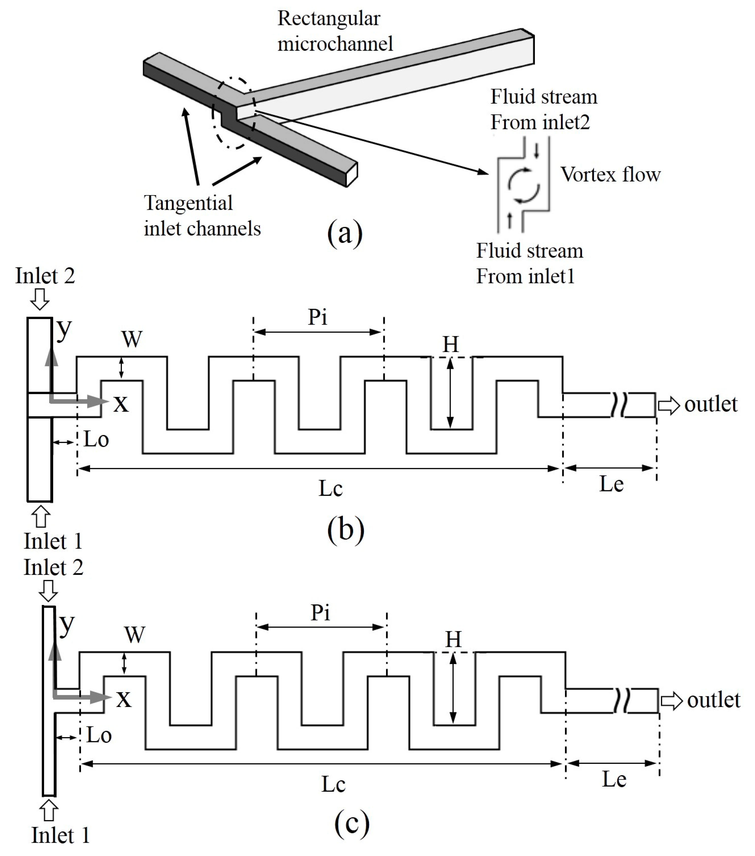
17]. A novel design of micromixer that generates vortical flow in a rectangular microchannel with tangentially aligned input channels was introduce by Ansari
et al. [
18]. They report that the vortex initially formed at the inlet of a rectangular microchannel increases the interfacial area of the fluid streams by stretching, and thus the mixing enhances.
As mentioned above, a variety of numerical and experimental studies have been conducted for different types of serpentine micromixers, and it is also clear from the literature review that the non-aligned input channels can promote mixing in a straight microchannel with the aid of initially formed vortical flow. However, there was no systematic work to investigate the effect of non-aligned input channels on the mixing performance of any specific types of micromixer including serpentine micromixers. In the present work, a numerical investigation on mixing and flow structure in a serpentine micromixer with non-aligned input channels has been performed to investigate the effects of non-aligned inputs on mixing in serpentine channel. Mixing index in this micromixer has been evaluated and compared with a serpentine micromixer with simple planar T-joint inputs. Analyses of mixing and flow structure have been performed for a wide range of Reynolds number ranging from 0.1 to 120. Pressure drop as a function of Reynolds number also has been evaluated.
3. Numerical Analysis
In this study, flow and mixing behavior were analyzed using a commercial Computational Fluid Dynamics (CFD) code, ANSYS CFX-12.1 [
19]. This commercial code resolves three-dimensional steady Navier–Stokes and mass conservation equations using the finite volume method. In the present analysis, the following continuity and Navier–Stokes equations were used:
where ρ, 𝛎 and
V represent density, kinematic viscosity, and velocity of fluid, respectively. To study the mixing phenomena, water and a solution of dye water at 25 °C were employed as the working fluids. For a fluid with constant density and viscosity, advection–diffusion type equation [
20] was constructed by combining the relative mass flux term with the mass conservation equation of the fluids, which is characterized as follows:
where,
C and α represent the concentration of dye water and diffusivity coefficient, respectively. The above equation was used to determine the mass fraction of the individual element all over the solution domain. To solve the above equations the following boundary conditions were considered. Pure water at 25 °C is introduced at the Inlet 1 and the dye water solution enters at Inlet 2 with zero and one mass fraction, respectively. The water used in this simulation has the following physical properties: dynamic viscocity of 0.9 × 10
−3 kg/ms and density of 9.998 × 10
2 kg/m
3.
Constant velocities were assigned at the inlets, and a zero static pressure was quantified at the outlet of the computational domain. No-slip condition was applied at the walls. ANSYS ICEM 12.1 was used to create an unstructured hexahedral grid system in the computational domain. The numerical simulation is generally involved with numerical diffusion error which arises due to the discretization of the convection terms in the Navier–Stokes equations. In this study, a higher-order numerical scheme [
21] was used for the convection terms to minimize the discretization error. The SIMPLEC procedure [
22] was used for pressure–velocity relation. The governing equations and numerical methods used in this work are described in more detail in a previous work [
23]. For the convergence criteria, 10
−7 was selected as a root mean square (RMS) residual value.
Mixing was quantified by resolving the variance of fluids in the micromixer. The variance of the fluids was evaluated at a cross-section of the micromixer, which is perpendicular to the flow. The variance of the mass fraction on a cross-section was formulated as follows:
where,
N and
ci represent the total number of sampling points within the cross-section and mass-fraction at sampling point,
i, respectively, and optimal mixing mass fraction is denoted by
Cm. The optimal mixing mass fraction value is 0.5 for completely mixed mixtures of fluids. Mixing index,
i.e., degree of mixing at a cross-sectional plane, was formulated as follows:
where, σ and σ
max represent the concentration standard deviation in a cross-section at any axial location and the maximum standard deviation at the exit. Higher mixing index represents higher mixing performance. The mixing index, zero, indicates completely separated streams (
), and 1 indicates completely mixed streams (σ = 0). The Reynolds number is defined in this work as follows:
where
D is the hydraulic diameter of the main channel and µ is the dynamic viscosity of the fluid.
4. Results and Discussion
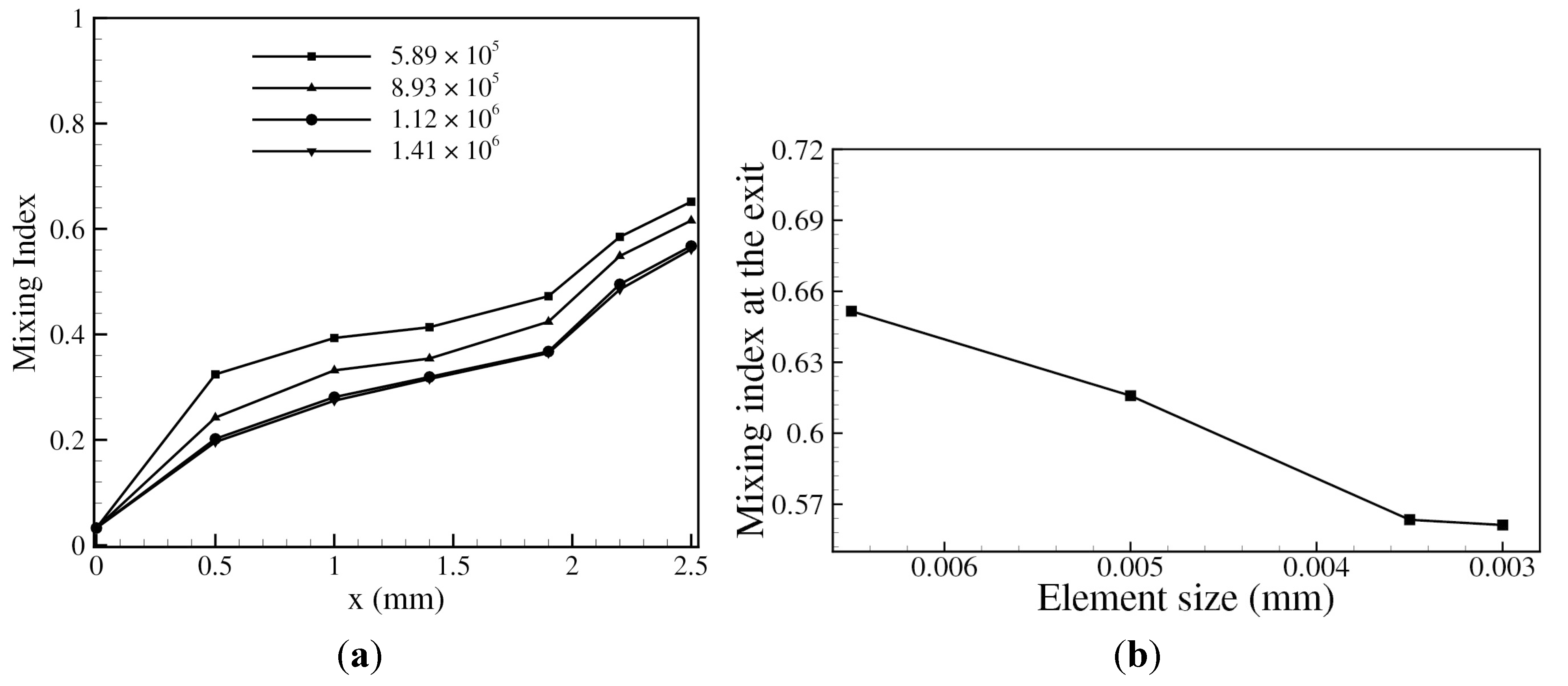
To determine the optimal number of computational meshes, a grid-sensitivity test was performed at Re = 45. Four different structured grid systems with the numbers of nodes ranging from 5.89 × 10
5 to 1.41 × 10
6, which corresponds to a range of mesh element size from 3.0 µm to 6.5 µm (in
x-direction), were tested as shown in
Figure 2. From these results, the grid system with 1.12 × 10
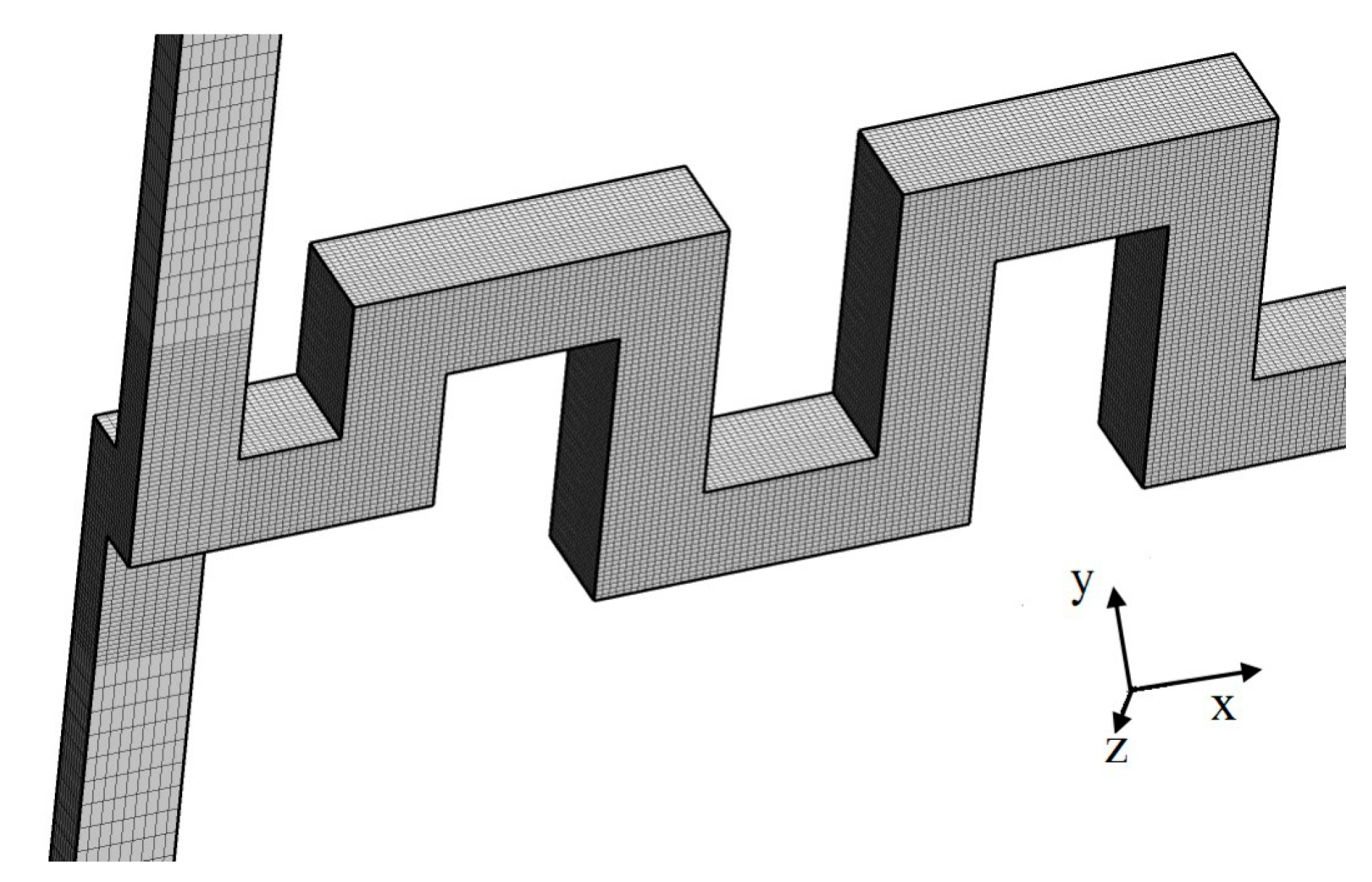
6 nodes, which corresponds to mesh element size of 3.5 µm, was determined as the optimum grid system for further calculations. An example of the hexahedral grid system employed in this study, is represented in
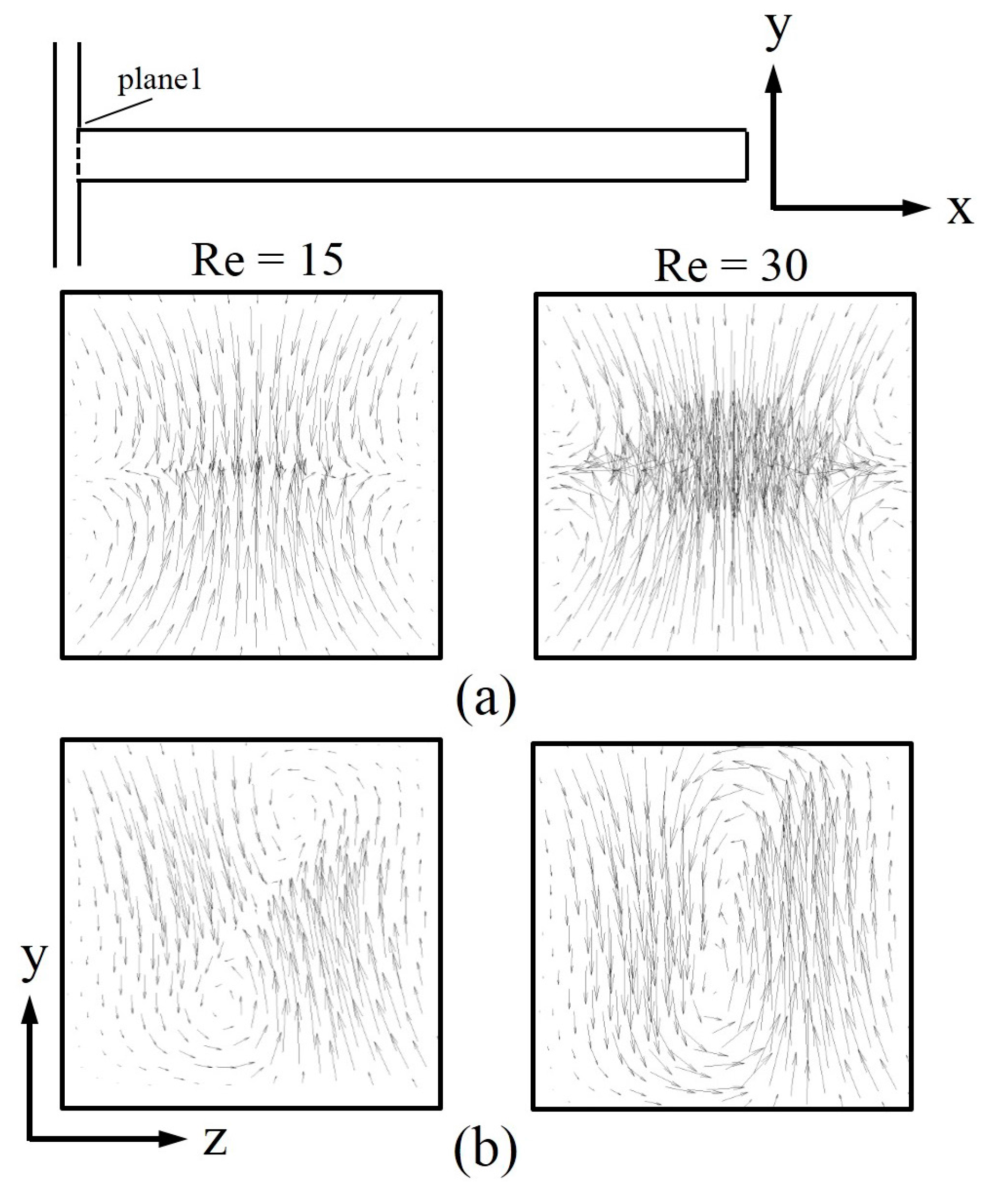
Figure 3. To understand the effect of tangentially aligned input channels on flow structure in the micromixer, velocity vectors are plotted at Reynolds number, 15 and 30, in
Figure 4. The velocity vectors are plotted on
y–
z plane at the inlet of the main channel (
x = 0.0 mm) indicated by dotted line.
Figure 4a,b illustrate the velocity vectors on
y–
z plane in the micromixers with simple T-joint and tangentially aligned input channels, respectively. Velocity vectors in the micromixer with simple T-joint are almost identical at Re = 15 and 30, and no vortical flow is visualized throughout the cross-sectional area. On the other hand, the micromixer with tangentially aligned input channels generates a vortical flow in the cross-section even at Reynolds number, where a couple of counter rotating vortices of similar scale are visualized. At Re = 30, a strong transverse flow is visualized and magnitude of the velocity vectors are uniformly distributed throughout the cross-sectional plane, which potentially causes a difference in mixing.
Figure 2.
Grid-dependency test at Re = 45: (a) number of nodes and (b) mesh element size.
Figure 2.
Grid-dependency test at Re = 45: (a) number of nodes and (b) mesh element size.
Figure 3.
An example of hexahedral grid system.
Figure 3.
An example of hexahedral grid system.
Figure 4.
Velocity vector plots on y–z plane at inlet for Reynolds numbers, 15 and 30: (a) Micromixer with simple T-joint inlet; and (b) micromixer with tangentially aligned input channels.
Figure 4.
Velocity vector plots on y–z plane at inlet for Reynolds numbers, 15 and 30: (a) Micromixer with simple T-joint inlet; and (b) micromixer with tangentially aligned input channels.
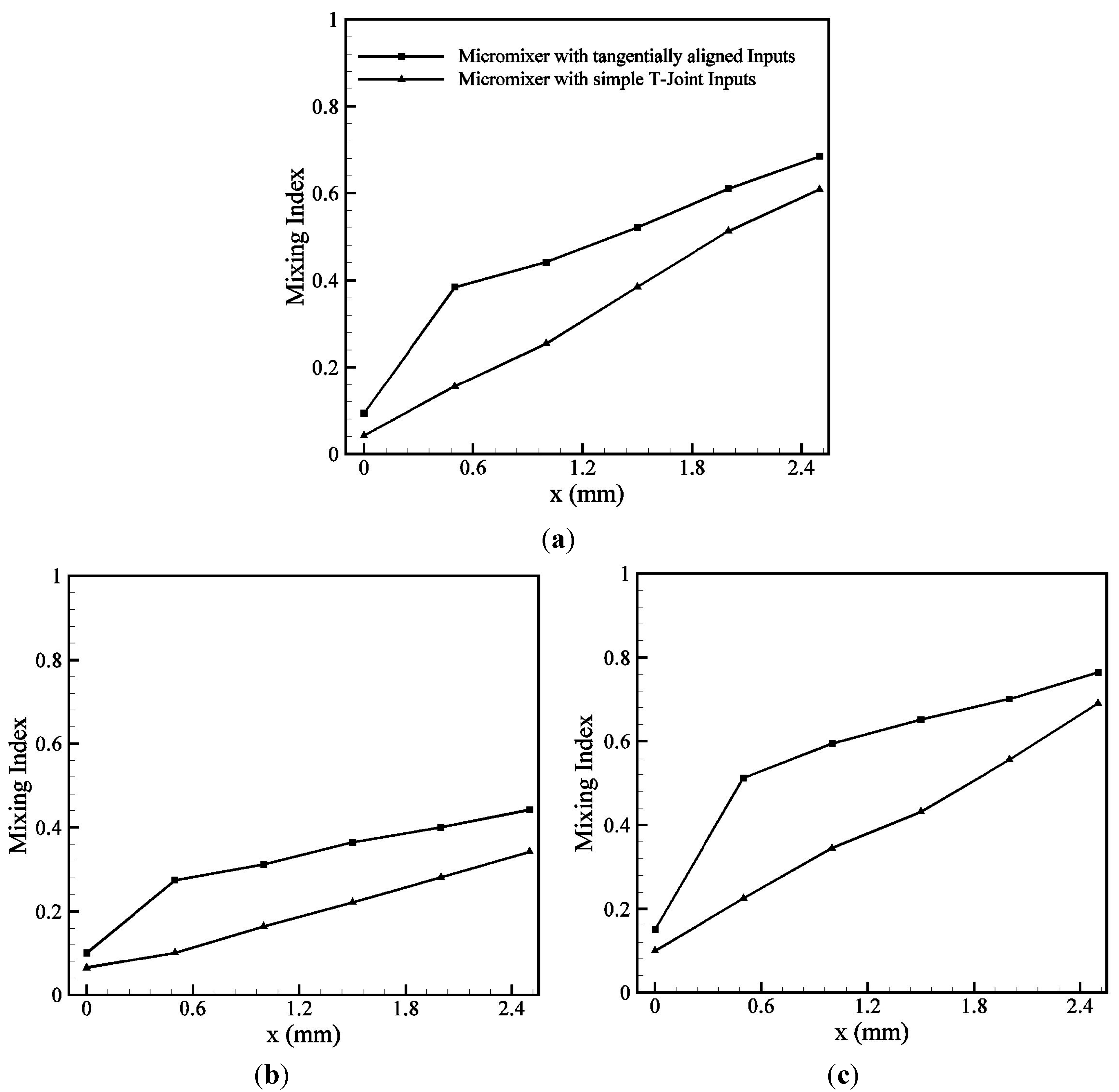
The development of the mixing index along the axis of the serpentine micromixers with simple T-joint and tangentially aligned input channels at different Reynolds numbers, 0.1, 45, and 90, are shown in
Figure 5a–c, respectively. These figures show that mixing index in the serpentine micromixer with simple T-joint inlet increases steadily along the channel length. On the other hand, a rapid increase in the mixing happens near the inlet joint in the serpentine micromixer with tangentially aligned input channels, and the mixing index increases slowly thereafter. The vortical flow induced by the tangentially aligned input channels shown in
Figure 4, enhances the mixing performance near the inlet as compare to the simple T-joint inlet micromixer.
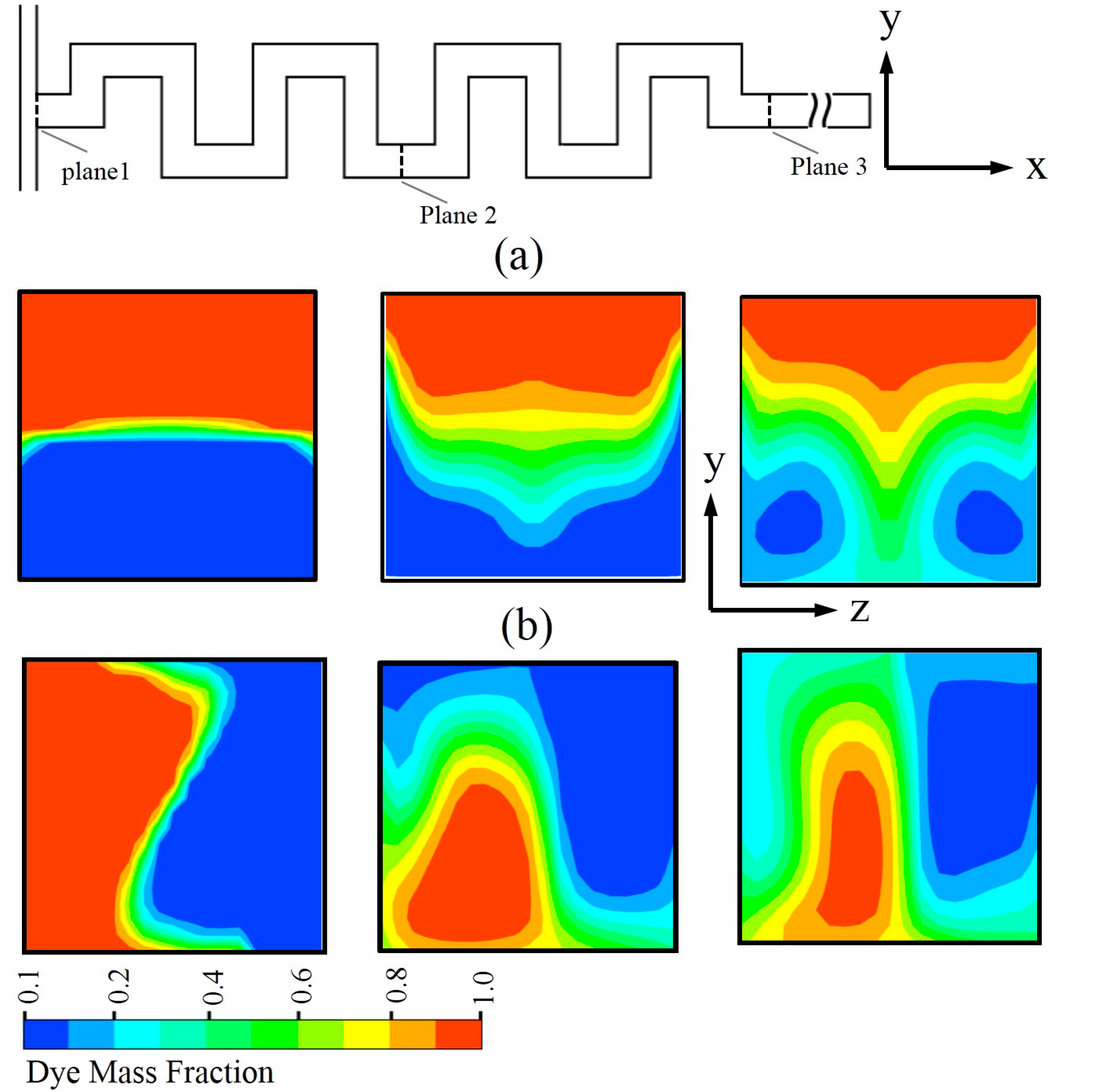
Mass fraction distributions of dye water on three
y–
z planes (indicated by dotted lines) perpendicular to the direction of flow at Reynolds number, 30, are plotted in
Figure 6. The comparison shows that the serpentine micromixer with tangentially aligned inputs offers enhanced mixing performance compared to that with T-joint inlet. As the flow proceeds along the channel, transvers flow develops which increase the interfacial area between the fluids, and thus the mixing index increases. At Plane 1, located at the inlet of the main channel, the serpentine micromixer with planar T-joint inlet (
Figure 6a) represents that the interface between the two fluids are nearly parallel, while the micromixer with tangentially aligned inputs (
Figure 6b) shows the distorted, and thus, extended interface. This phenomenon has potential effect to enhance the mixing performance throughout the Reynolds number range tested in this work compared to the serpentine micromixer with simple T-joint inlet as shown in
Figure 7. At low Reynolds number (Re << 1), mixing is dominated by the residence time of fluids and depends upon the total path of the flow. As the Reynolds number increases beyond Re = 1, mixing index decreases due to the reduction in the residence time until it reaches the minimum at Re = 15. If the Reynolds number increases beyond this Reynolds number, the residence time further reduces, but the transverse flows become active and mixing starts to increase. Similar mixing pattern is also observed in
Figure 5.
Figure 5.
Mixing index distributions along the channel length at different Reynolds numbers: (a) Re = 0.1; (b) Re = 45; and (c) Re = 90.
Figure 5.
Mixing index distributions along the channel length at different Reynolds numbers: (a) Re = 0.1; (b) Re = 45; and (c) Re = 90.
Figure 6.
Dye mass fraction distributions at various y–z planes (Re = 30): (a) Micromixer with simple T-joint inlet; and (b) micromixer with tangentially aligned input channels.
Figure 6.
Dye mass fraction distributions at various y–z planes (Re = 30): (a) Micromixer with simple T-joint inlet; and (b) micromixer with tangentially aligned input channels.
Figure 7.
Variations of mixing index at the exit of micromixer with Reynolds number.
Figure 7.
Variations of mixing index at the exit of micromixer with Reynolds number.
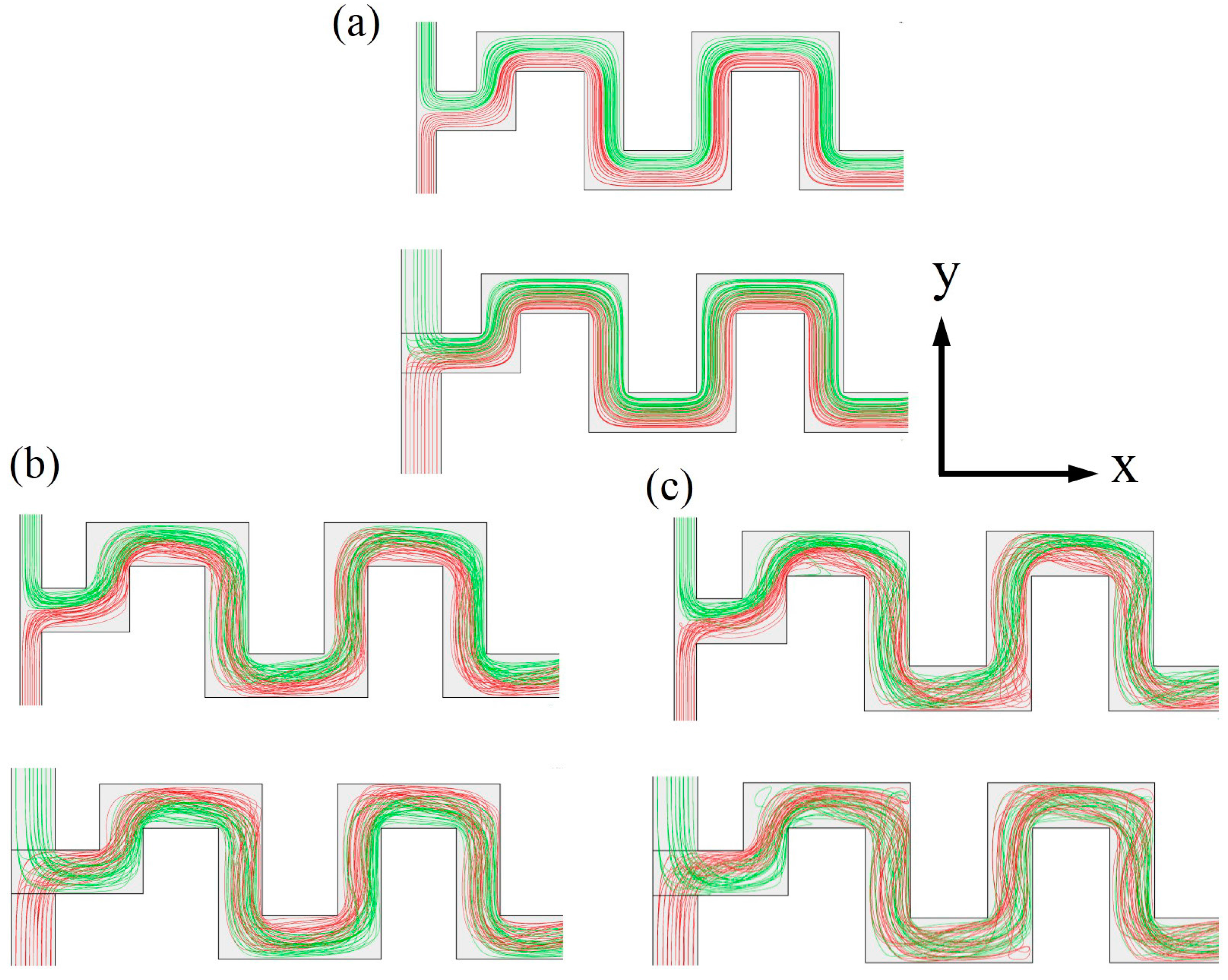
To analyze the mixing mechanism in the serpentine micromixers with and without the non-aligned inputs, the projected streamlines initiated from Inlet 1 and Inlet 2 are plotted in
Figure 8 at Re = 0.1, 30, and 90. In
Figure 8a, the micromixer with T-joint inlet (top figure) shows that at the low Reynolds number, 0.1, the fluids from Inlet 1 and Inlet 2 collide at the T-joint, but the streamlines continue to follow the paths along their own side after the collision, and thus are not mixed throughout the channel length. On the other hand, in the micromixer with non-aligned inputs, the streamlines initiated from two different inlets cross each other due to the initial swirl caused by the non-aligned inputs as shown in
Figure 4, and hence the mixing enhances.
Figure 8b,c shows that mixing of the streamlines of two different fluids occurs generally at Re = 30 and 90, but the mixing of the streamlines is obviously more active in the micromixer with non-aligned inputs than the simple T-joint micromixer. The mixing of streamlines increases with the increase in the Reynolds number indicating enhancement in the mixing performance.
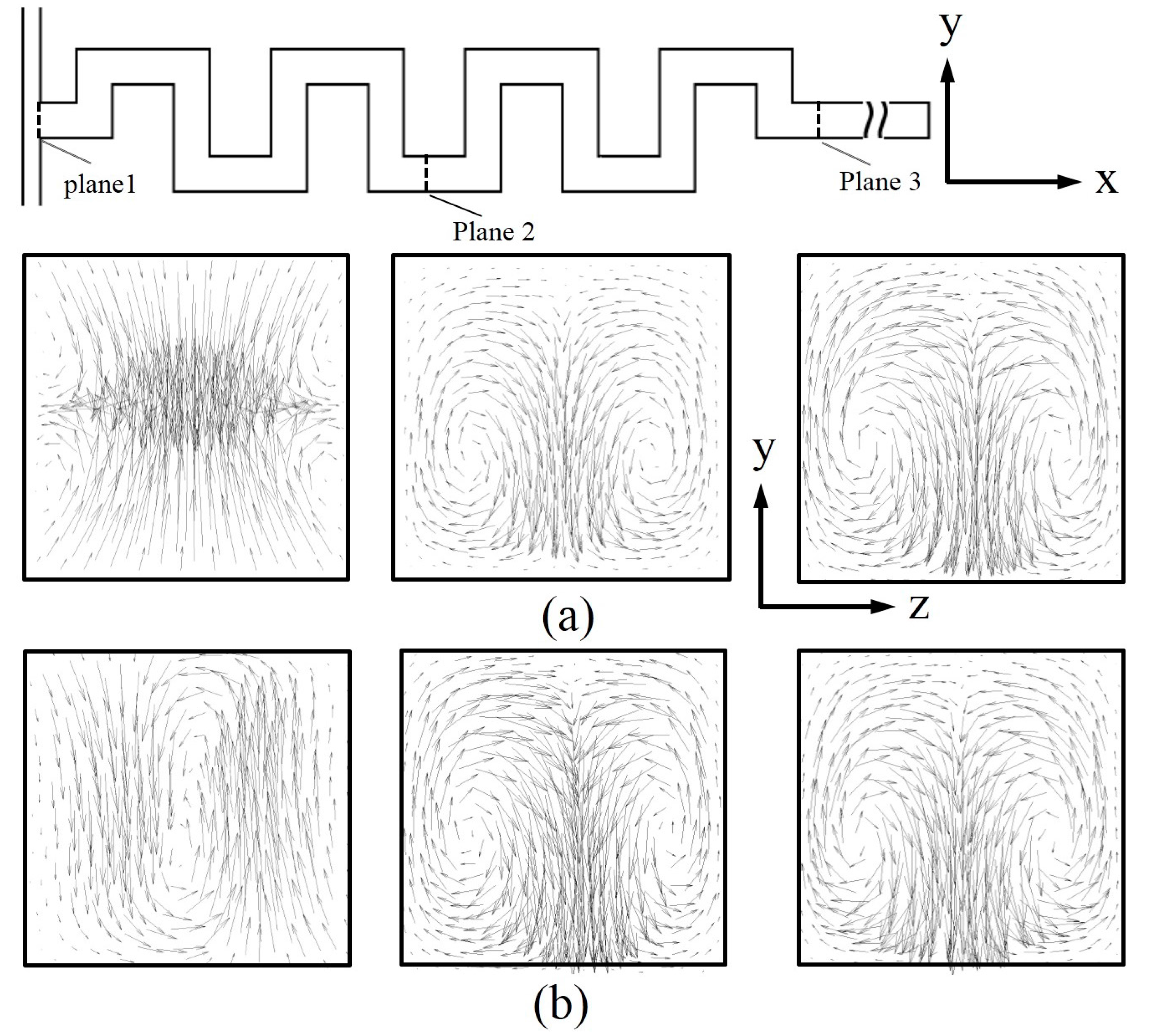
Velocity vectors on successive cross-sectional planes (indicated by dotted lines) along the axis of micromixer for both the simple T-joint inlets and tangentially aligned inlets micromixers, are shown in
Figure 9 at Reynolds number, 30. At Plane 1, the two micromixers show different flow structures; the tangentially aligned inlets micromixer shows a big single vortex occupy whole plane which strengthens the vertical motion downstream, and the simple T-joint inlets micromixer shows symmetric collision of two fluid streams. In downstream sections (Planes 2 and 3), a couple of counter-rotating vortices are commonly found for both the micromixers, but the tangentially aligned inlets micromixer shows stronger vertical motion.
Figure 8.
Projected streamlines initiated from Inlet 1 and Inlet 2 for the two different serpentine micromixers: (a) Re = 0.1; (b) Re = 30; and (c) Re = 90.
Figure 8.
Projected streamlines initiated from Inlet 1 and Inlet 2 for the two different serpentine micromixers: (a) Re = 0.1; (b) Re = 30; and (c) Re = 90.
Figure 9.
Velocity vectors on y–z planes for Reynolds number, 30 (Planes 1, 2, and 3 from left to right, respectively): (a) Micromixer with simple T-joint inlets; and (b) micromixer with tangentially aligned input channels.
Figure 9.
Velocity vectors on y–z planes for Reynolds number, 30 (Planes 1, 2, and 3 from left to right, respectively): (a) Micromixer with simple T-joint inlets; and (b) micromixer with tangentially aligned input channels.
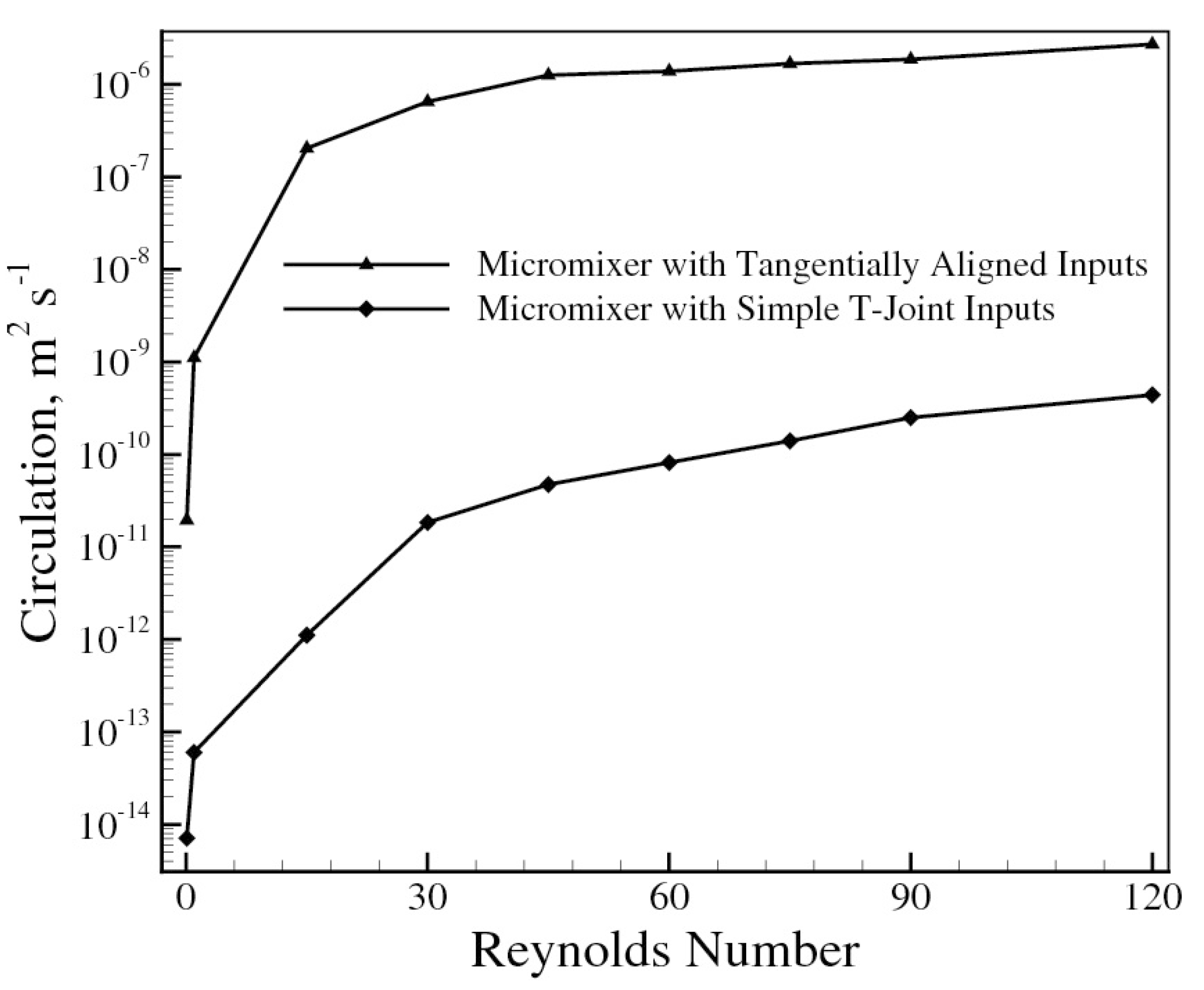
The circulation on
y–
z cross-sectional plane, Ω
x, is calculated by integrating the streamwise vorticity, ω
x over the entire cross-sectional area as follows:
where
vy and
vz are velocity components in
y and
z directions, respectively. Circulation represents the magnitude of the vertical motion on the cross-sectional plane.
Figure 10 demonstrates the circulation distribution on the
y–
z plane at the exit of the micromixers in a Reynolds number ranging from 1 to 120. The circulation increases rapidly as the Reynolds number increase until Re = 30 and continue to increase steadily thereafter.
Figure 10 depicts that the tangentially aligned inputs micromixer has much higher circulation over the simple T-joints inputs micromixer throughout the working range, which contributes to the enhancement of mixing performance.
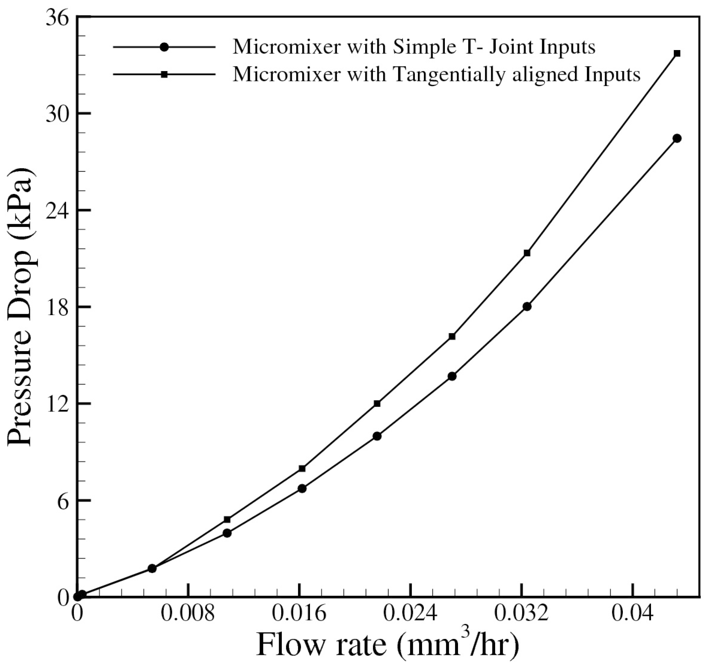
Figure 11 represents the pressure drop variations with flow rate for the two serpentine micromixers with simple T-joint inputs and tangentially aligned inputs. The required pumping power to drive the flow in the micromixer is directly proportional to the pressure drop. To calculate the pressure drop, equal axial channel length was considered for both serpentine micromixers. The flow rate is directly proportional to the Reynolds number. As generally expected, the pressure drop increases as the flow rate increases. At lower flow rate less than 0.888 (mm
3/h), where transverse flow is inactive, the effect of tangentially aligned inputs on pressure drop is negligible. Beyond this range of flow rate, the serpentine micromixer with tangentially aligned input channels shows higher pressure drop throughout the working range.
Figure 10.
Variations of normalized circulation at the exit of micromixer with Reynolds number.
Figure 10.
Variations of normalized circulation at the exit of micromixer with Reynolds number.
Figure 11.
Variation of pressure drop with flow rate.
Figure 11.
Variation of pressure drop with flow rate.


