1. Introduction
One of the major requirements for a fully-integrated microfluidic device is the ability to automatically mix and control fluids in a reasonable time [
1,
2]. However, in microfluidic systems, the Reynolds number is usually less than 1 and, consequently, molecular diffusion becomes the main mixing mechanism, which leads to overall slow processes.
In recent years, acoustic streaming has become one of the most effective techniques, with no mechanical parts, for promoting mixing and pumping in fluidic devices [
2,
3,
4,
5], since this technique overcomes the limitations of mixing in micro scale systems. Many authors have approached this phenomenon of acoustic streaming through numerical simulations and experimental studies [
4,
6,
7,
8,
9,
10]. Typically, acoustic streaming uses a piezoelectric transducer for generating acoustic waves that are absorbed by the fluids. This mechanism promotes pressure gradients that, when properly induced, generate the fluid flow and mixing [
11,
12,
13]. Specifically, the harmonic oscillation of the solid boundary near the fluid generates the propagation of the acoustic waves in the fluid as well as a steady mean flow field [
12].
In particular, one of the materials that has received much attention due to its piezoelectric properties and advantages relatively to the most traditional piezoelectric material (such as the ceramics or quartz) is the poly(vinylidene fluoride) (PVDF) polymer in its β phase [
14,
15,
16]. This material has one of the best piezoelectric responses among polymers (as examples of
d33 values of several polymers, 35 pC/N for PVDF, 33.5 pC/N for P(VDF-TrFE), 2 pC/N for Parylene-C or 16.5 pC/N for PI (β-CN) APB/ODPA [
17,
18]) and has great potential for microprocessing and integration in microdevices, since it can be easily deposited into thin-films. PVDF, when processed in the β phase, presents good mechanical, acoustic and thermal properties. Specifically, PVDF presents low acoustic and mechanical impedances, which are important characteristics for the generation and propagation of acoustic waves in fluids. PVDF is transparent (higher than 70% in the visible spectral range [
19]), which is also an important requirement for lab-on-a-chip devices comprising optical detection, mainly when the transducer is located in the optical path [
16].
Relative to the acoustic streaming numerical studies, the most relevant works in the field are focused on the acoustic propagation and streaming between parallel plates with infinite extent, as approached by Nyborg [
13] or within cylindrical channels of constant cross-section and infinite length, as approached by Frampton [
4]. Additionally, the majority of the studies (following the early research of Eckart [
20] and Nyborg [
13]) consider SAW devices [
21,
22] or plane travelling waves, while the present work is focused in non-planar waves, generated by a transducer with a small width when compared with the cuvette width. Since most of the acoustic mixing studies are based on ceramic piezoelectric transducers (examples in [
23,
24]), this work brings a new perception of the use of piezoelectric polymeric thin-films as acoustic transducers, actuated at high frequencies.
From previous work, it is already known how the acoustic propagation occurs when the fluid domain is actuated at 10 MHz by a single piezoelectric transducer centered relatively to the fluidic domain [
25,
26]. Therefore, the present work is focused on studying the acoustic streaming propagation and consequent global flows in a 2D domain (which is representative of a 3D domain) actuated by a transducer placed asymmetrically relatively to the fluidic domain (
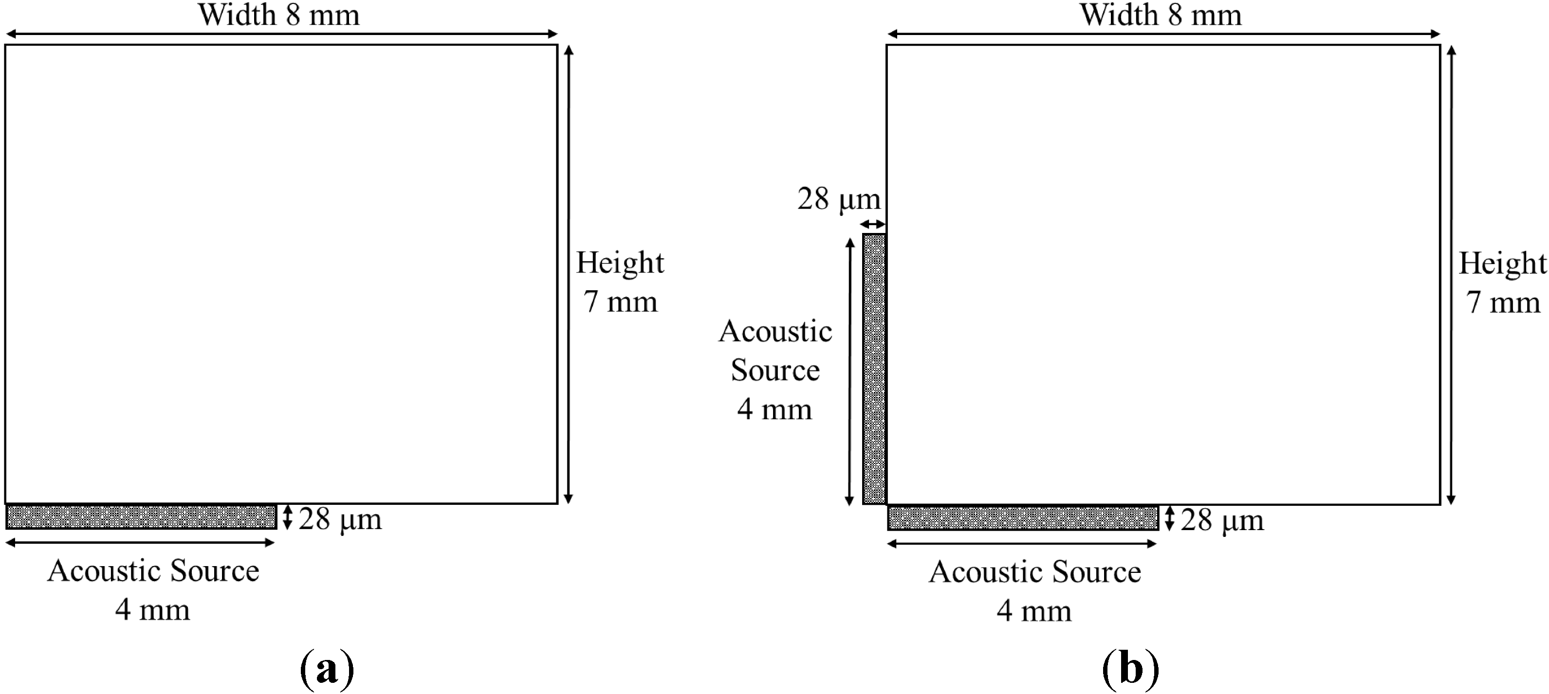
Figure 1a), and by two perpendicular transducers (as represented in
Figure 1b) in order to evaluate the potential of this positioning for pumping applications and compare it with the previous geometries with a single centered transducer [
26]. Through this analysis, we will evaluate the effect of the acoustic waves superposition and of the acoustic reflections in the global flows profiles.
By adding numerical simulations of the same arrangement as the one presented in
Figure 1, but at microscale (0.8 mm × 0.7 mm cuvette and 0.4 mm length transducers), this paper also intends to study the potential of the simultaneous actuation of two transducers for implementation in microdevices.
Figure 1.
Macroscale version of the cuvette and piezoelectric transducers positioning for studying the acoustic streaming phenomena. (a) One transducer. (b) Two transducers perpendicularly placed.
Figure 1.
Macroscale version of the cuvette and piezoelectric transducers positioning for studying the acoustic streaming phenomena. (a) One transducer. (b) Two transducers perpendicularly placed.
Mathematical Model
The numerical model of the acoustic streaming phenomenon generated by a piezoelectric transducer consists of a multiphysics problem comprising the piezoelectric effect, the piezo-fluid interface, the acoustic propagation and the global steady streaming. Each one of these mechanisms can be mathematically described by a proper set of equations.
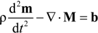
The piezoelectric effect comprises the differential Equations (1) and (2), two constitutive equations of the piezoelectric material (3) and (4) and the Hooke’s law (5) [
3].
In the above equations,
ρ is the density,
M the mechanical stress,
m the mechanical displacement of the piezoelectric material,
b the volume force vector actuating in the piezoelectric material,
D the electrical displacement,
dM and
dE the piezoelectric coefficients,
E the electric field,
S the mechanical strain,
εM the dielectric permittivity and
sE the elastic coefficient. The β-PVDF parameters are listed in [
17]. Relatively to the electric boundary conditions, the transducer boundary in contact with the cuvette is connected to the ground, the opposite boundary is connected to a sinusoidal voltage (with fixed amplitude and frequency) and the lateral faces of the transducer present electric continuity.
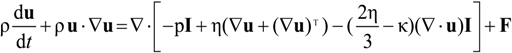
The piezoelectric effect generates acoustic waves that propagate into the fluid. As predicted from the piezoelectric constitutive equations, the amplitude of the pressure waves in the transducer-fluid interface is directly proportional to the transducer electric voltage actuation. In the present work, the maximum voltage limit was established by the 24 Vpp DC source and, therefore, 24 Vpp was selected as the actuation voltage, both in numerical and experimental tests. The propagation of these waves to the fluids depends on the interface pressure, frequency and fluid properties (density, viscosity and speed of sound), as well as the acoustic matching layers (that can absorb or reflect the acoustic waves). Therefore, the numerical simulations of the acoustic streaming flows are based on the compressible Navier-Stokes momentum (6) and continuity (7) equations, where ρ is the fluid density,
u the velocity field vector,
p the pressure, η the dynamic viscosity, κ the dilatational viscosity,
F the volume force field and
I the identity matrix.
The acoustic streaming boundary conditions are detailed in [
25]. The piezo-fluid boundary is defined by a vector with normal and tangential components, correspondent to the stress generated by the piezoelectric transducer, stating that the stress is a continuous function across the boundary.
The acoustic streaming problem must be decomposed in two subproblems, one directed to short timescales and another to long timescales, in order to overcome the large difference between the piezoelectric vibration and fluid flow timescales [
27]. This procedure is based on the Nyborg approach [
13], firstly developed in 1953, that considers an acoustic driving force, obtained from the instantaneous propagation of the acoustic waves, which affects the global acoustic flow. This approach was followed by several authors [
3,
4,
9,
11,
28], who developed significant studies in the numerical acoustic streaming simulation at microscale, based on the instantaneous acoustic propagation time averaging. In this procedure, the Navier-Stokes variables (pressure, density and velocity) are expanded in zero order, first order and second order components. The first order variables represent the instantaneous acoustic flow, as these variables describe the damped propagation of the acoustic wave. After solving the first order equations, a time averaged acoustic force is determined. The time averaged value is obtained by integration of the Navier-Stokes force term during one wave period (after the periodic solution stabilization) followed by its division by the wave period. The time averaged force is then applied as the source term for solving the second order Navier-Stokes equations. This second order problem describes the steady global flow, that represents the average acoustic streaming effects in a large time scale [
4,
9,
25].
The mathematical model was solved for the cuvettes represented in
Figure 1, in order to evaluate the acoustic streaming generated by β-PVDF transducers. The numerical model was implemented in a commercial software (COMSOL Multiphysics, Burlington, MA, USA). The first order equations were solved in a transient simulation during 50 μs, with a 1 ns time step, while the second order equations were solved in a stationary state. The first and second order problems were solved using an unsymmetric multifrontal sparse LU factorization package solver, with 1 × 10
−8 relative tolerance and 10,000 maximum number of iterations. The domain was meshed with a structured quadrilateral mesh, where each element has a 1.67 μm × 3.33 μm dimension, which guarantees about 26 elements for each acoustic wavelength in the propagation distance. The effect of the mesh dimensions in the acoustic streaming results is discussed in [
25]. In addition to the numerical simulations, some experimental tests were performed with a prototype system, for validating the simulated flows and evaluating the performance of β-PVDF thin-films for acoustic transducers applications.
2. Experimental Setup and Transducer Electrical Characterization
In the acoustic streaming experimental tests, the authors used 28 μm thick β-PVDF transducers to generate the acoustic waves. β-PVDF transducers were fabricated through spin-coating techniques [
19]. Iniatially, in order to electrically characterize the β-PVDF transducers, we developed a prototype with eight transducers, each with a 2 × 2 cm
2 area. The prototype consisted of a Printed Circuit Board (PCB) with the corresponding Radio Frequency (RF) connectors, with the 28 μm thickness β-PVDF transducers glued to it, as shown in
Figure 2. The transducers were glued to the PCB with silver conductive paint, since this material fixes the transducer without blocking the piezoelectric vibration. The mechanical damping of the silver conductive paint was neglected in the simulations.
Figure 2.
Printed Circuit Board with Radio Frequency (RF) connectors and the 2 × 2 cm2 β-poly(vinylidene fluoride) (β-PVDF) (28 µm thickness) transducers, with aluminum electrodes, glued to the Printed Circuit Board (PCB).
Figure 2.
Printed Circuit Board with Radio Frequency (RF) connectors and the 2 × 2 cm2 β-poly(vinylidene fluoride) (β-PVDF) (28 µm thickness) transducers, with aluminum electrodes, glued to the Printed Circuit Board (PCB).
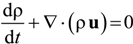
After fabrication of the prototype, the β-PVDF transducers were electrically characterized using a previously calibrated Vector Network Analyzer (VNA) F8357A from Agilent. The VNA experimental curve, presented in
Figure 3, was obtained after connecting the RF connectors of the prototype to the VNA (without electric matching circuit) and measuring the
S-parameters for a frequency range up to 100 MHz. The
S-parameters are determined from the amplitude and phase of the reflected and transmitted waves and describe the electric energy reflection in the transducer input. These
S-parameters correspond to the elements of a dispersion matrix, and each specific element of the matrix is given by
![]()
, where
![]()
is the amplitude of the incident voltage wave and
![]()
is the amplitude of the emergent (reflected) wave. In particular, the
S11 parameter corresponds to the non-dimensional reflection coefficient and allows us to quantify the electric signal amplitude that effectively actuates the transducer [
29].
Figure 3.
Vector Network Analyzer (VNA) curve of the S11 parameter (reflection coefficient) measured for the 28 μm thickness PVDF transducer without electric matching.
Figure 3.
Vector Network Analyzer (VNA) curve of the S11 parameter (reflection coefficient) measured for the 28 μm thickness PVDF transducer without electric matching.
In order to optimize the acoustic transmission, the actuation frequency must equal the mechanical resonance frequency of the transducer, which is given by
Fr =
c/2
t, where
Fr is the resonance frequency,
c the speed of the sound and
t the thickness of the transducer. Since the β-PVDF films have a 28 μm thickness and the speed of sound in PVDF is 2.2 km/s, the theoretical resonance frequency is 39 MHz. Therefore, the transducer must show smaller reflection coefficient values around the theoretical resonance frequency, indicating maximum transmission. A small oscillation (indicative of minor electric reflected signal) was detected in the VNA curve at 34.2 MHz (
Figure 3) and, consequently, a matching circuit for electric driving at this frequency was implemented, for enhancing the electrical transmission for the transducers and improve the vibration, limiting the electric transmission in all the other frequencies. The resonance frequency deviation, relatively to the expected 39 MHz, results from the experimental setup interferences (copper wire, silver conductive paint and RF connectors) that are not removed by the system calibration.
Figure 4 shows the schematic of the 34.2 MHz matching circuit and the VNA curve of the piezoelectric transducer after implementation of the matching circuit. The matching circuit was designed based on the Smith diagram [
29] obtained through the VNA measurements, and optimized in the Ansoft Designer software. The Smith diagram consists of a polar representation of the reflection coefficient and is an auxiliary tool in the electric matching process, which occurs by adding impedance and/or admittance components, in series or parallel [
29]. The quality of the matching circuit for improving the electric transmission at 34.2 MHz was experimentally evaluated through a VNA analysis, presented in
Figure 4b.
After the electrical characterization of the transducers, they were actuated by a 9 dB RF signal, using a RF Signal Generator (N9319A from Agilent, Santa Clara, CA, USA) for generating a sinusoidal signal with constant frequency and a RF amplifier (Coaxial Amplifier ZHL-6A from Mini-Circuits, Brooklyn, NY, USA) to guarantee enough power to actuate the transducers, connected to a 24 Vpp DC source.
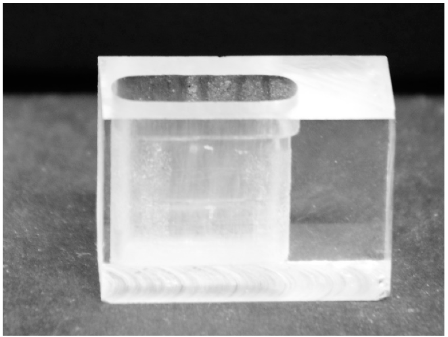
Poly(methyl methacrylate) (PMMA) cuvettes (
Figure 5) with 8 mm width, 7 mm height and 2.5 mm thickness were fabricated and used to determine the streaming patterns in the cuvettes. The slight curve over the cuvette thickness, observed in
Figure 5, was neglected in the two dimensional numerical simulations.
Figure 4.
(a) Scheme of the electric matching circuit for the PVDF actuation. (b) VNA curve of the S11 parameter (reflection coefficient) measured for the 28 μm thickness PVDF transducer after electric matching implementation. The minimum reflection peak is located at 34.2 MHz.
Figure 4.
(a) Scheme of the electric matching circuit for the PVDF actuation. (b) VNA curve of the S11 parameter (reflection coefficient) measured for the 28 μm thickness PVDF transducer after electric matching implementation. The minimum reflection peak is located at 34.2 MHz.
Figure 5.
Poly(methyl methacrylate) (PMMA) cuvette, with 8 mm width, 7 mm height and 2.5 mm thickness used in the acoustic streaming experimental tests.
Figure 5.
Poly(methyl methacrylate) (PMMA) cuvette, with 8 mm width, 7 mm height and 2.5 mm thickness used in the acoustic streaming experimental tests.
The streaming patterns were assessed by a simplified PIV (Particle Image Velocimetry) white light system, using 10 μm diameter polystyrene particles suspended in water. Image processing tools ImageJ and PIVlab [
30] were used for processing the PIV results, in order to determine the streaming patterns. Each PIV measurement was performed during one minute with a HDR-UX7E camera from Sony (Tokyo, Japan), with 6.1 megapixel spatial resolution and using a 10 fps sampling rate. Since the cuvette walls have a low thickness (1 mm) the acquisition system was able to capture the particles flow in the cuvette.
The experimental results were compared to numerical results, obtained by solving the piezoelectric and first and second order Navier-Stokes equations (the detailed model can be found in [
25]). The same actuation and experimental conditions were considered, as were the water properties at room temperature.
4. Conclusions
The paper reported a numerical and experimental study of the effect of β-PVDF piezoelectric transducers in the acoustic streaming patterns in a fluidic domain. Two transducer arrangements were studied: on one side, a 28 μm thick β-PVDF piezoelectric transducer was placed asymmetrically in the bottom left side of a cuvette containing the fluidic domain and, on the other side, two β-PVDF transducers were placed perpendicularly to each other, in the lower left corner of a cuvette. The results show that the number of transducers and their positioning affects the shape and the number of recirculation areas in the acoustic streaming flows and, therefore, affects the mixture.
When compared to the authors’ previous works, where a single transducer was placed in the center of a cuvette face, the acoustic actuation lead to the formation of two large symmetric recirculation areas, which does not occur in the present work, showing that the position of the transducer relatively to the fluidic domain has a great impact on the acoustic streaming flow. Furthermore, when compared with the previous published works, this paper presents a comparison between numerical and experimental flows obtained by acoustic actuation of a β-PVDF transducer at 34.2 MHz.
These results show that the high frequency actuation of β-PVDF piezoelectric transducers, in addition to a great potential for miniaturizing and integration in microfluidic devices, can be an effective alternative for enhancing the streaming, due to the streaming patterns that cover the whole domain. The obtained global flows suggest that the presented transducer arrangements have great potential for mixing and pumping, being an alternative to the previous geometries studied by the authors.


 , where
  is the amplitude of the incident voltage wave and
  is the amplitude of the emergent (reflected) wave. In particular, the S11 parameter corresponds to the non-dimensional reflection coefficient and allows us to quantify the electric signal amplitude that effectively actuates the transducer [29].
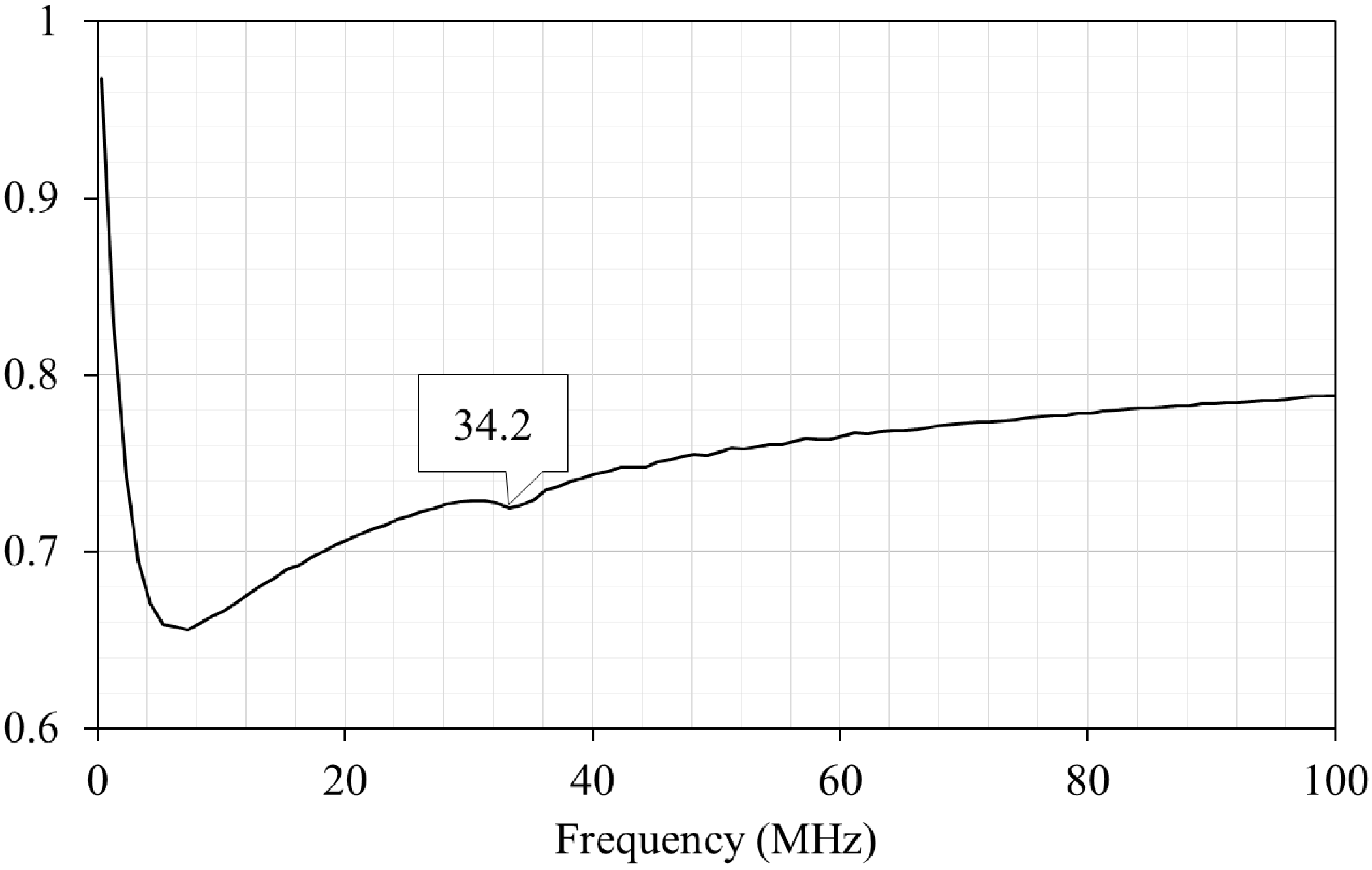


 , where δ is the viscous layer thickness, ν the kinetic viscosity of the medium and ω the wave angular frequency [32]. As the microcuvette dimensions decrease, the viscous boundary layer effects become more relevant to the acoustic streaming flows.