Article

Stop-flow Lithography to Continuously Fabricate Microlens Structures Utilizing an Adjustable Three-Dimensional Mask

1
Department of Mechanical and Mechatronic Engineering, National Taiwan Ocean University, Keelung 202-24, Taiwan
2
Center for Marine Mechatronic Systems (CMMS), National Taiwan Ocean University, Keelung 202-24, Taiwan
*
Author to whom correspondence should be addressed.
Micromachines 2014, 5(3), 667-680; https://doi.org/10.3390/mi5030667
Submission received: 11 August 2014 / Revised: 1 September 2014 / Accepted: 3 September 2014 / Published: 10 September 2014

Abstract

:
Stop-flow lithography (SFL) is a microfluidic-based particle synthesis method, in which photolithography with a two dimensional (2D) photomask is performed in situ within a microfluidic environment to fabricate multifunctional microstructures. Here, we modified the SFL technique by utilizing an adjustable electrostatic-force-modulated 3D (EFM-3D) mask to continuously fabricate microlens structures for high-throughput production. The adjustable EFM-3D mask contains a layer filled with a UV-absorbing liquid and transparent elastomer structures in the shape of microlenses between two conductive glass substrates. An acrylate oligomer stream is photopolymerized via the microscope projection photolithography, where the EFM-3D mask was set at the field-stop plane of the microscope, thus forming the microlens structures. The produced microlens structures flow downstream without adhesion to the polydimethysiloxane (PDMS) microchannel surfaces due to the existence of an oxygen-aided inhibition layer. Microlens structures with variations in curvature and aperture can be produced by changing objective magnifications, controlling the morphology of the EFM-3D mask through electrostatic force, and varying the concentration of UV-light absorption dyes. We have successfully demonstrated to produce microlens structures with an aperture ranging from 50 μm to 2 mm and the smallest focus spot size of 0.59 μm. Our proposed method allows one to fabricate microlens structures in a fast, simple and high-throughput mode for application in micro-optical systems.

1. Introduction

Stop-flow lithography (SFL) technique [1], which was first proposed by Professor Doyle’s group, has been intensively used in the fabrication of various complex or multifunctional microstructures with applications that range from mechanical to biomedical engineering, such as synthesis of colloidal, glass, and silicon microcomponents [2,3], nonspherical superparamagnetic particles [4,5], cell-laden microgel particles [6,7], and multifunctional encoded particles for biomolecule analysis [8,9]. This technique combines the advantages of microscope projection photolithography and microfluidics to continuously form morphologically complex particles. Briefly, the continuous flow of the hydrogel precursor within a microfluidic channel is stopped before performing in situ photolithography, where the hydrogel precursor was exposed at regular intervals to ultraviolet (UV) light patterned by a photomask to produce discrete particles. The produced particles can be repeatedly patterned and flow downstream without clogging due to the inhibition of free-radical polymerization near polydimethysiloxane (PDMS) surfaces of the microchannel. However, the binary mask, which was used in projection photolithography in this technique, imposed the restriction to fabricate the three dimensional (3D) microstructures with continuously changed surfaces, such as microlens structures. To this end, a digital micromirror device (DMD) [10,11,12] or a liquid crystal display (LCD) [13] has been used as a dynamic photomask to fabricate the microlens arrays or 3D microstructures through projection photopolymerization. However, the surface roughness of the microlens arrays is a considerable issue due to the limited resolution (4 μm image pixel size) of the DMD or LCD, which can significantly reduce the optical performance of the microlens arrays. Instead, our previous work [14] utilized an adjustable electrostatic-force-modulated 3D (EFM-3D) mask to successfully demonstrate the feasibility of fabricating microlens arrays in millimeter scale with surface roughness below 25 nm to provide a good optical property. However, our previous work directly combined the EFM-3D mask with the PDMS microchannel using a thin layer of glycerol between two components. Only millimeter-size microlens arrays were fabricated by using this techniques. To attempt to fabricate the micronmeter-size microlens arrays in our current work, we can set a microscope objective between the EFM-3D mask and the PDMS microchannels. The morphology of the EFM-3D mask is then projected into the PDMS microchannels through the microscope objective, which can reduce the size of the corresponding microlens due to the convergence of the UV light.
Here, we modified the SFL technique by utilizing an adjustable EFM-3D mask to continuously fabricate microlens structures ranging from 50 μm to 2 mm for high-throughput production. The EFM-3D mask consists of transparent microlens structures that are elastic in nature and filled with index-matching oil that contains UV-light-absorbing dyes for purposes of light attenuation. The elastic microlens structures can be dynamically adjustable through electrostatic force modulation. An acrylate oligomer stream is photopolymerized via the microscope projection photolithography, where the EFM-3D mask was set at the field-stop plane of the microscope. The pulsed UV light passes through the EFM-3D mask to polymerize the acrylate oligomer and generate the microlens structures in a PDMS microchannel. The corresponding microlens structures flow downstream without adhesion to the surface of the microchannel due to the existence of an oxygen-aided inhibition layer on the PDMS surface. The curvature and aperture of the microlens structures can be produced by changing objective magnifications, controlling the morphology of the EFM-3D mask through electrostatic force modulation, and varying the concentration of UV-light absorption dyes. Our proposed techniques provide a fast, simple and cost-effective method for continuous mass-production processes for application in micro-optical systems.

2. Experimental Section

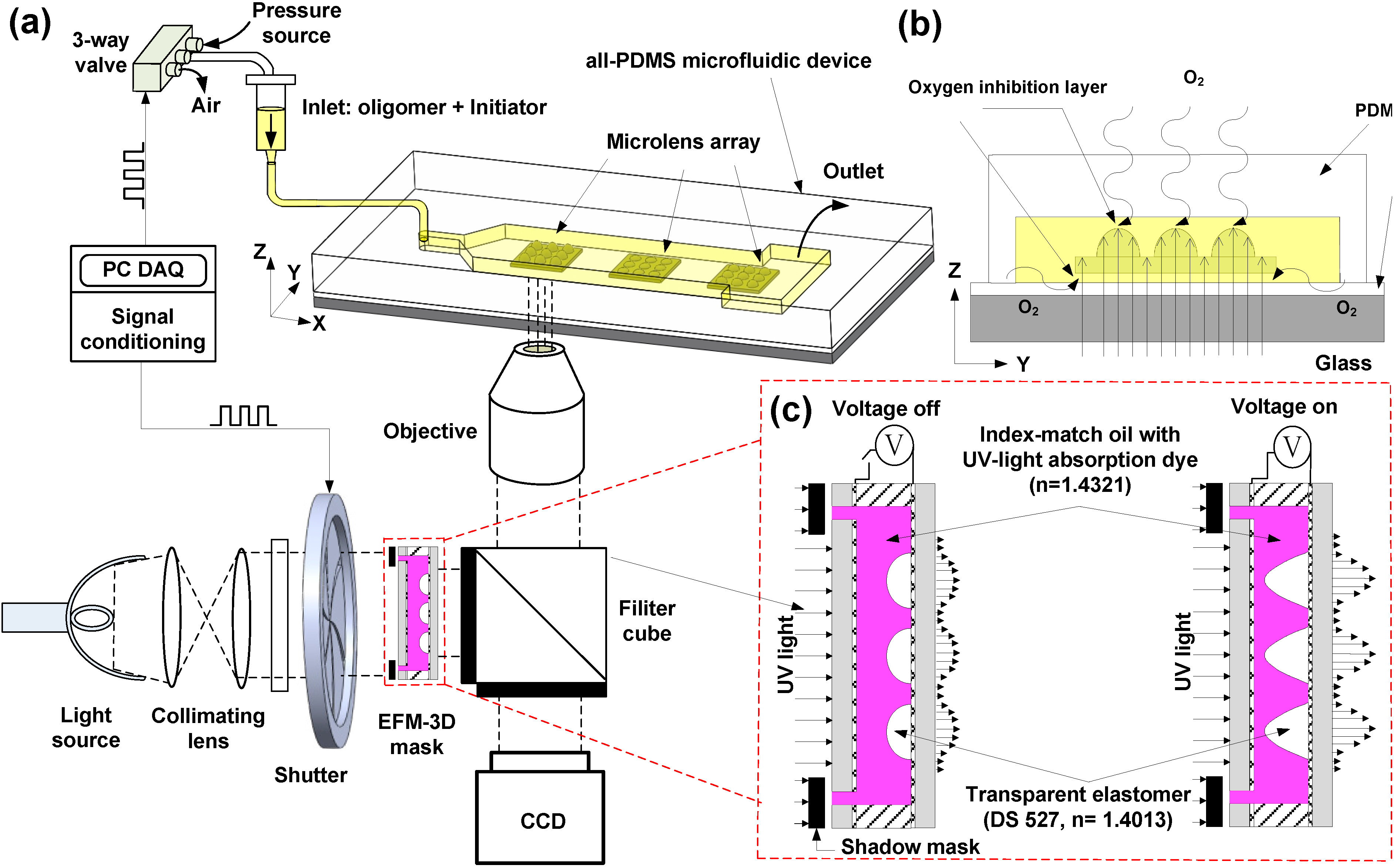
2.1. Principle of Operation

Figure 1 schematically illustrates the design concept of stop-flow lithography to fabricate microlens arrays utilizing an adjustable EFM-3D mask for high-throughput production in microchannels. The system consists of two main components: an inverted microscope to perform a projection photolithography and PDMS microfluidic devices. The microscope projection photolithography is performed by setting the EFM-3D mask at the field-stop plane of the microscope as shown in Figure 1a. The EFM-3D mask is made from a transparent elastomer structure and filled with a UV-absorbing liquid that contains index-matching oil (hexadecane) mixed with UV-light absorbing dyes (Oil-Red-O) to provide light attenuation. The refractive index of Oil-Red-O dye in hexadecane (dye oil) is 1.432, which is close to the refractive index (1.407) of the transparent elastomer structure to avoid the refraction occurring within the EFM-3D mask. A shadow mask placed onto the EFM-3D mask defines the margin of the produced microlens structures. ITO glass, placed on the top and bottom of the structure, allows for the application of electrostatic forces needed to deform the elastomer structures in the vertical direction (Figure 1c).
An acrylate oligomer stream containing a photosensitive initiator is pumped into the rectangular PDMS microchannel. On stopping the flow, UV light is pulsed through the EFM-3D mask, resulting in the gradient distribution profile of the light intensity, and then projected on the PDMS microchannel through the preset objective. This polymerizes the acrylate oligomer and generates the microlens structures in the PDMS microchannel. Rapid polymerization kinetics permits quick formation (<1 s) of the microlens structures. The microlens structures are then allowed to flow downstream without adhesion on the walls of the PDMS microchannel surfaces due to the existence of the oxygen-aided inhibition layer on the PDMS surfaces as shown in Figure 1b. The oxygen-aided inhibition layer arises from the diffusion of molecular oxygen through the PDMS surface that reacts with an initiator species to form chain-terminating peroxide radicals, creating an unpolymerized lubrication layer approximately 3 m thick on the PDMS surfaces [1,15] to enable the microlens structures suspended within PDMS microchannel. The suspended microlens structures were collected in the reservoir of the microchannel, pipetted out using ethanol solution, and then collected in an Eppendorf tube. The Eppendorf tube was repeated to centrifuge to settle down the microlens structures, remove the supernatant (un-crosslinked liquid), and add new ethanol, so as to obtain a collection of the microlens structures suspended in the clean ethanol.
The intensity distribution of UV light after passing through the EFM-3D mask can be adjusted by changing the concentration of UV-light absorption dyes in the dye oil and/or the morphology of the elastomer structures within the EFM-3D mask through electrostatic force modulation. On application of a voltage across the EFM-3D mask, the induced electrostatic force causes the elastomer structures to vertically deform, morphing from an arc-shaped morphology into a parabolic or near conical shape (Figure 1c). When the voltage is removed, the elastomer structures return to the original arc-shaped morphology, thanks to the elastic nature of the material. Changing the intensity distribution modifies the morphology of the corresponding microlens structures. Therefore, the curvature and aperture of the microlens structures can be produced by changing objective magnifications, controlling the morphology of the EFM-3D mask through electrostatic force modulation, and varying the concentration of UV-light absorption dyes. The entire procedure of stopping the oligomer flow, adjusting the morphology of the EFM-3D mask by applying a voltage, exposing the EFM-3D mask to a pulsed UV light, and pumping the oligomer fluid to collect the microlens arrays is repeated to achieve the continuously high-throughput fabrication of the microlens with various curvatures in a single step process.
Figure 1. (a) Schematic illustrating the design concept for the continuous, high-throughput fabrication of microlens structures in microchannels. An adjustable electrostatic-force-modulated (EFM-3D) mask is inserted in the field-stop plane of the microscope. The acrylate oligomer stream flows through the polydimethysiloxane (PDMS) microfluidic device. The microlens structures are polymerized by a UV light transmitted through the electrostatic-force-modulated 3D (EFM-3D) mask and the microscope objective, and then flow downstream without adhesion on the PDMS surfaces. (b) The side-view shows the photopolymerized microlens structures, the intensity distribution after passing through the EFM-3D mask, and the unpolymerized oxygen-aided inhibition layer on the PDMS surfaces that allows the microlens structures to flow easily after being formed. (c) Schematic illustrating the intensity distribution of UV light after passing through the EFM-3D mask operated before and after applying voltages.
Micromachines 05 00667 g001

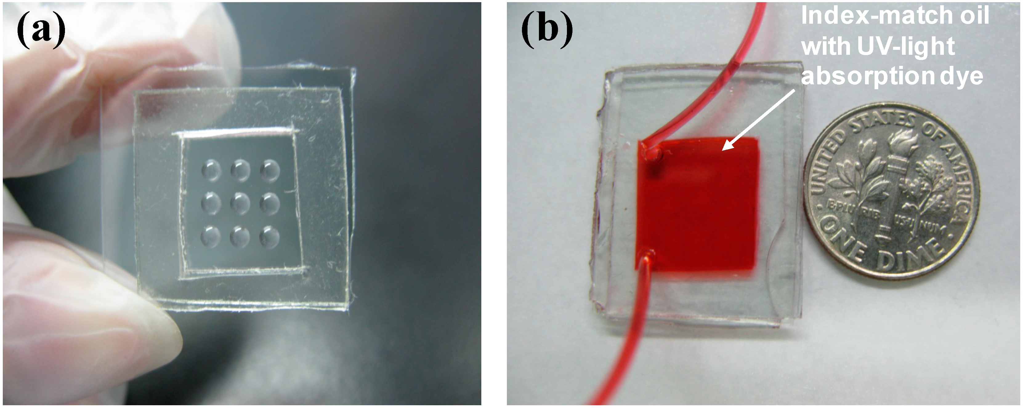
2.2. Fabrication of Adjustable EFM-3D Mask and PDMS Microchannel

To fabricate the adjustable EFM-3D mask, Teflon AF (DuPont Inc., Wilmington, DE, USA) was first patterned onto the ITO glass substrate via a lift-off process, creating a pattern of hydrophobic and hydrophilic surfaces. The transparent liquid elastomer (DS-527, Dow Corning, Midland, MI, USA) was spun at 500 rpm for 15 s to form a corresponding microdroplet pattern on the modified ITO substrates. The DS-527 microdroplets were cured by heating at 65 °C for 30 min, resulting in an array of solid structures with elastic properties as shown in Figure 2a. An additional ITO glass was placed above the patterned ITO substrate with a 1 mm PDMS spacer. The structure was then filled with a UV-absorbing liquid that contains oil (hexadecane) mixed with UV-light absorbing dyes (Oil-Red-O) (Figure 2b). The PDMS microchannel was fabricated using a standard soft lithography process. Briefly, an SU-8 mold (MicroChem, Westborough, MA, USA) was made on a silicon wafer using standard lithography techniques. The PDMS microchannel was cast from the SU-8 mold. An additional glass slide coated with a thin PDMS film was subsequently bonded onto the PDMS microchannel immediately after an oxygen plasma surface treatment. The PDMS microchannels have a rectangular shape with L = 4.5 cm in length, W = 1 cm in wide, and H = 300 μm in height.
Figure 2. Images of the EFM-3D mask (a) before and (b) after filling with the index-matching oil (hexadecane) that contains UV-light absorption dye.
Micromachines 05 00667 g002

2.3. Materials

The acrylate oligomer was made using 5% (v/v) solutions of Darocur 1173 (D1173, Sigma Aldrich, St. Louis, MO, USA) initiator in 1,6-hexanediol diacrylate (HDDA, Sigma Aldrich). The viscosity and refractive index of the HDDA is 6 cP and 1.457 at 20 °C. Hexadecane (Fluka) with a dynamic viscosity of 8 cP, dielectric constant of 2.05, and refractive index of 1.432 was used as the index-matching oil. Oil-Red-O dye (Sigma Aldrich) mixed with hexadecane provided the UV-light absorption at λmax = 359 nm. Transparent DS-527 (Sylgard 527, Dow Corning), a silicone dielectric gel with a high dielectric constant of 2.95, was used as an elastomer structure within the EFM-3D mask. The refractive index of the DS-527 is 1.407, which is close to the refractive index (1.432) of the Oil-Red-O dye in hexadecane (dye oil). The four different concentrations (w/v) of Oil-Red-O in hexadecane used in this study were 0.005, 0.01, 0.015, and 0.03. PDMS (Sylgard 184, Dow Corning) was used to fabricate the PDMS microchannel.

2.4. Experimental Setup of the Stop-Flow Lithography

The control to sequentially pump and stop the flow of the acrylate oligomer within the PDMS microchannel was set up according to the stop-flow lithography technique [1] as shown in Figure 1a. Briefly, a compressed-air source connected to a pressure regulator was used to drive oligomer flow inside the PDMS microchannel. Downstream of the regulator, a 3-way solenoid valve (Lee Inc., Princeton, NC, USA) controlled by a Labview program (National Instruments Inc., Austin, TX, USA) was used to switch rapidly between atmospheric pressure and the input pressure. After switching the 3-way solenoid valve to atmospheric pressure, the oligomer flow can be totally stopped in the PDMS microchannel within 0.14 s, which was measured by bead tracking experiments for the PDMS microchannels with L = 4.5 cm, W = 1 cm, H = 300 μm at input pressure of 3 psi. A collimated UV light equipped with a VS25 shutter system (Uniblitz Inc., Orlando, FL, USA) controlled by a VMM-T1 shutter driver provided specified pulses of the UV light.

3. Results and Discussion

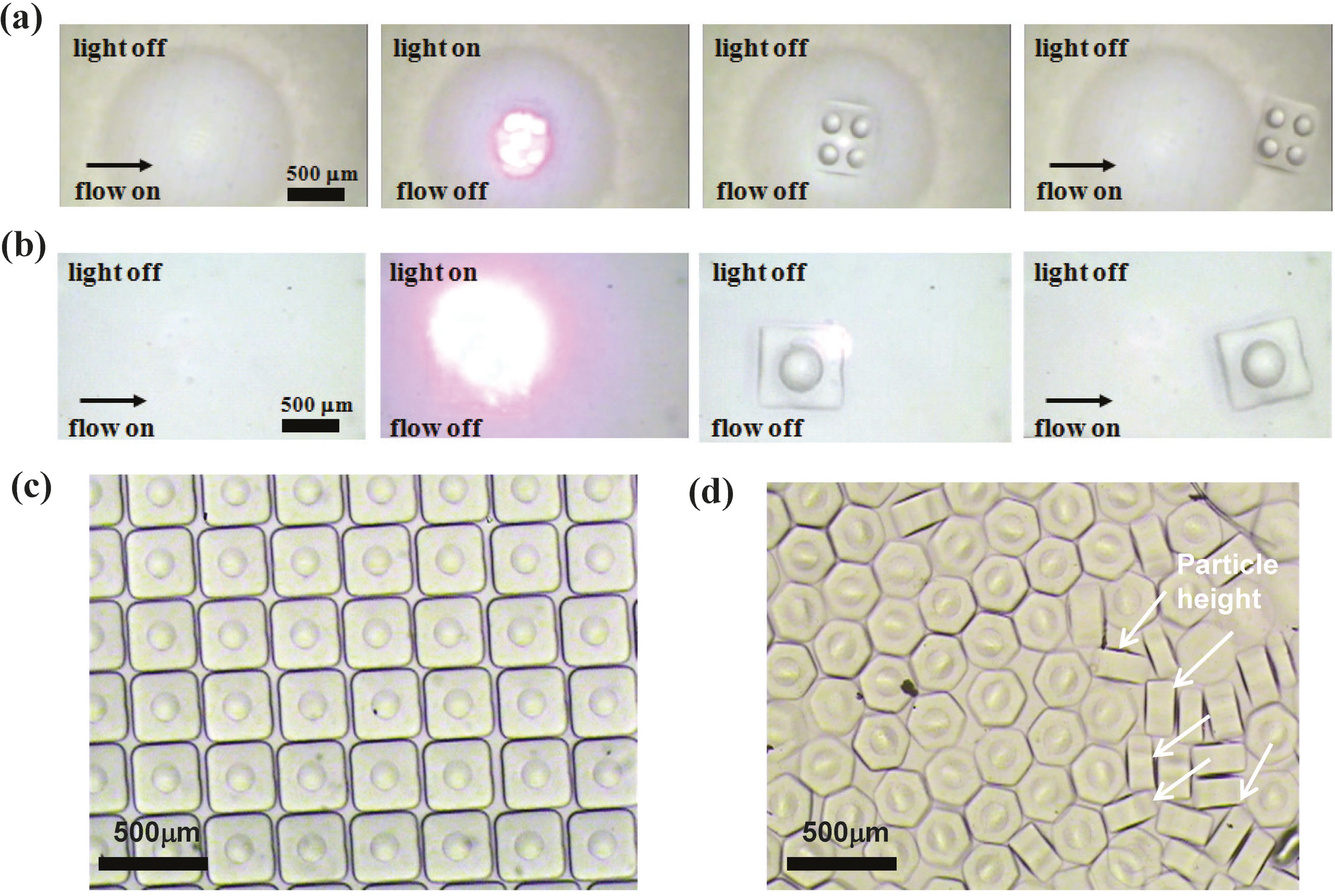
3.1. Photopolymerized Microlens Structures via EFM-3D Masks

Figure 3a,b illustrate the four-step process for producing the suspended 2 × 2 microlens array and single microlens in a PDMS microchannel via the EFM-3D mask filled with dye oils at a concentration of Cdye oil = 0.015 (w/v) and operated without applied voltages. The EFM-3D mask was set at the field-stop plane of the microscope equipped with a 4× objective. For production of a single microlens, only one elastomer structure with 2 mm in diameter and 0.341 mm in height was deposited within the EFM-3D mask; while for production of 2 × 2 microlens array, 2 × 2 elastomer structures with 0.7 mm in diameter were deposited. In the first step, an acrylate oligomer stream containing a photosensitive initiator was pumped into a PDMS microchannel, and the flow was then completely stopped by closing the 3-way solenoid valve. The shutter then pulses open for 30 ms and close in the second and third steps, while the flow remains stopped. The pulsed UV light that passes through the EFM-3D mask can polymerize the acrylate oligomer, and generate the corresponding single microlens or 2 × 2 microlens array in the PDMS microchannel. In the final step, the polymerized single microlens or 2 × 2 microlens array was flushed out of the channel by opening the 3-way solenoid valve. The single microlens or 2 × 2 microlens array is allowed to flow downstream within the unpolymerized oligomer without adhesion on microchannel surfaces, due to the existence of an oxygen-aided inhibition layer at the PDMS surface. The four-step process can be repeated to achieve the continuous fabrication of the microlens structures. A shadow mask placed onto the EFM-3D mask defines the shape and size of the substrate of the produced microlens structures. The suspended microlens structures with square and hexagonal substrates were flushed downstream and collected in the reservoir of the microchannel as shown in Figure 3c,d. The thickness and uniformity of the substrate depends on the exposure time and uniformity of the UV light. Some of the polymerized single microlens structures collected at the downstream have turned on their sides showing the height of the microlens about 120 μm as shown in Figure 3d.
Figure 3. Images showing the four-step process for producing the suspended (a) 2 × 2 microlens array and (b) single microlens in a PDMS microchannel via the EFM-3D gray mask filled with dye oils at Cdye oil = 0.015 (w/v) and operated without applied voltages. The EFM-3D mask was set at the field-stop plane of the microscope equipped with a 4× objective. A shadow mask placed onto the EFM-3D mask defines the shape and size of the substrate of the produced microlens structures. The suspended microlens structures with (c) square and (d) hexagonal substrates were flushed downstream and collected in the reservoir of the microchannel. Some of the polymerized microlens structures have turned on their sides showing the height of the microlens as shown by white arrows in (d).
Micromachines 05 00667 g003

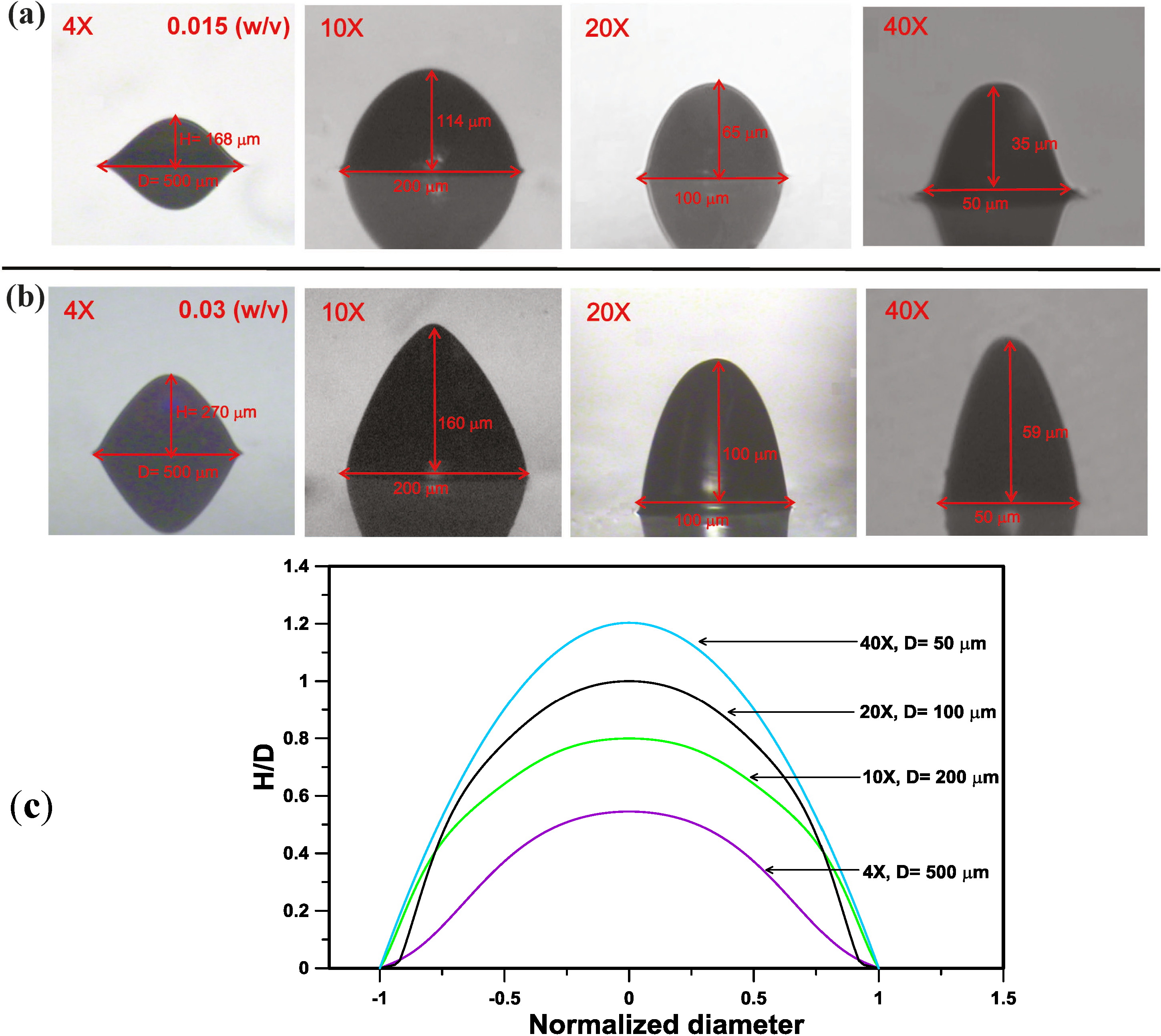
3.2. Morphology Control of the Photopolymerized Microlens Structures

To characterize the morphology of the microlens structures produced by changing objective magnifications and varying the concentration of UV-light absorption dyes (Cdye oil) within EFM-3D mask, the rectangular PDMS microchannel was directly bonded on a glass slide that did not have a thin PDMS coating. After the pulsed UV light passed through the EFM-3D mask, the produced microlens structures adhered to the surface of the glass slide, and the residual liquid was removed using compressed air. The morphology and non-dimensional height (H/D) of the produced microlens structures could be easily observed and characterized. One elastomer structure with 2 mm in diameter and 0.341 mm in height within the EFM-3D mask was used for production of a single microlens adhered on the glass surface.
Figure 4a,b shows the lateral images of the microlens structures produced by the EFM-3D mask filled with dye oils at a concentration of Cdye oil = 0.015 and 0.03 (w/v) for utilizing the different objective magnifications. Changing the objective magnifications from 4× to 40×, while keeping the concentration of dyes oil constant at Cdye oil = 0.015 or 0.03 (w/v), can decrease the aperture (diameter, D) of the microlens structures from D = 500 μm to 50 μm. Besides, changing the objective magnifications from 4× to 40× also decreased the height (H) of the microlens structures from H = 168 μm to 35 μm and 270 μm to 59 μm for Cdye oil = 0.015 and 0.03 (w/v), respectively. However, the nondimensional height (H/D) of the microlens structures increased from H/D = 0.34 to 0.7 and 0.54 to 1.2 for Cdye oil = 0.015 and 0.03 (w/v). Figure 4c shows the lateral profiles of the microlens structures produced in (b) at Cdye oil = 0.03 (w/v) by using 4× to 40× objectives, respectively. The lateral profiles and nondimensional sizes of the microlens structures were determined by using image processing process and mathematical curing fitting [14,16] from the lateral images in Figure 4b. The increase of the H/D as changing the objective magnifications from 4× to 40× attributes to the different numerical aperture (N.A.) of the objectives used to produce the microlens structures, such as the N.A. of 4× and 40× objectives are = 0.2 and 0.96, respectively. Higher N.A. of the objective possesses a larger angle of the light cone after passing through the objective, which causes more UV light refracting to the center part of the light intensity distribution. This effect results in the increase of the H/D of the produced microlens structures. Besides, changing the concentration (Cdye oil) of the dyes oil from 0.015 to 0.03 (w/v), while keeping objective magnifications constant, can increase the height (H) of the microlens structures, such as H = 168 μm for Cdye oil = 0.015 (w/v) and H = 270 μm for Cdye oil = 0.03 (w/v) by using 4× objective. The effect of the concentration of the dye oil (Cdye oil) on the distribution profile of the light intensity transmitted through the EFM-3D mask has been examined using optical simulation in our previous work [14]. Increasing the concentration (Cdye oil) of the dye oil changes the distribution profile of the light intensity from a flat shape to a parabolic shape, which is in turn to increase the height (H) of the produced microlens.
Figure 4. The lateral images of the microlens structures produced by EFM-3D mask filled with dye oils at a concentration of (a) Cdye oil = 0.015 and (b) 0.03 (w/v) for utilizing the different objective magnifications. (c) The lateral profiles of the microlens structures produced in (b) at Cdye oil = 0.03 (w/v) by using 4× to 40× objectives, respectively.
Micromachines 05 00667 g004
Figure 5 shows the nondimensional height (H/D) of the produced microlens structures with respect to the objective magnifications from 4× to 40× for the EFM-3D mask filled with dye oils at Cdye oil = 0.005 to 0.03 (w/v). For the EFM-3D mask filled with a fixed concentration (Cdye oil) of the dye oil, increasing the objective magnifications from 4× to 40× increased the H/D of the microlens structures. By using a fixed objective magnification, increasing the concentration (Cdye oil) of the dyes oil also increase the H/D of the microlens structures. Therefore, microlens structures with variations in curvature and aperture can be produced by changing objective magnifications and varying the concentration of UV-light absorption dyes within EFM-3D mask.
Figure 5. The nondimensional height (H/D) of the produced microlens structures with respect to the objective magnifications from 4× to 40× for the EFM-3D mask filled with dye oils at Cdye oil = 0.005 to 0.03 (w/v).
Micromachines 05 00667 g005

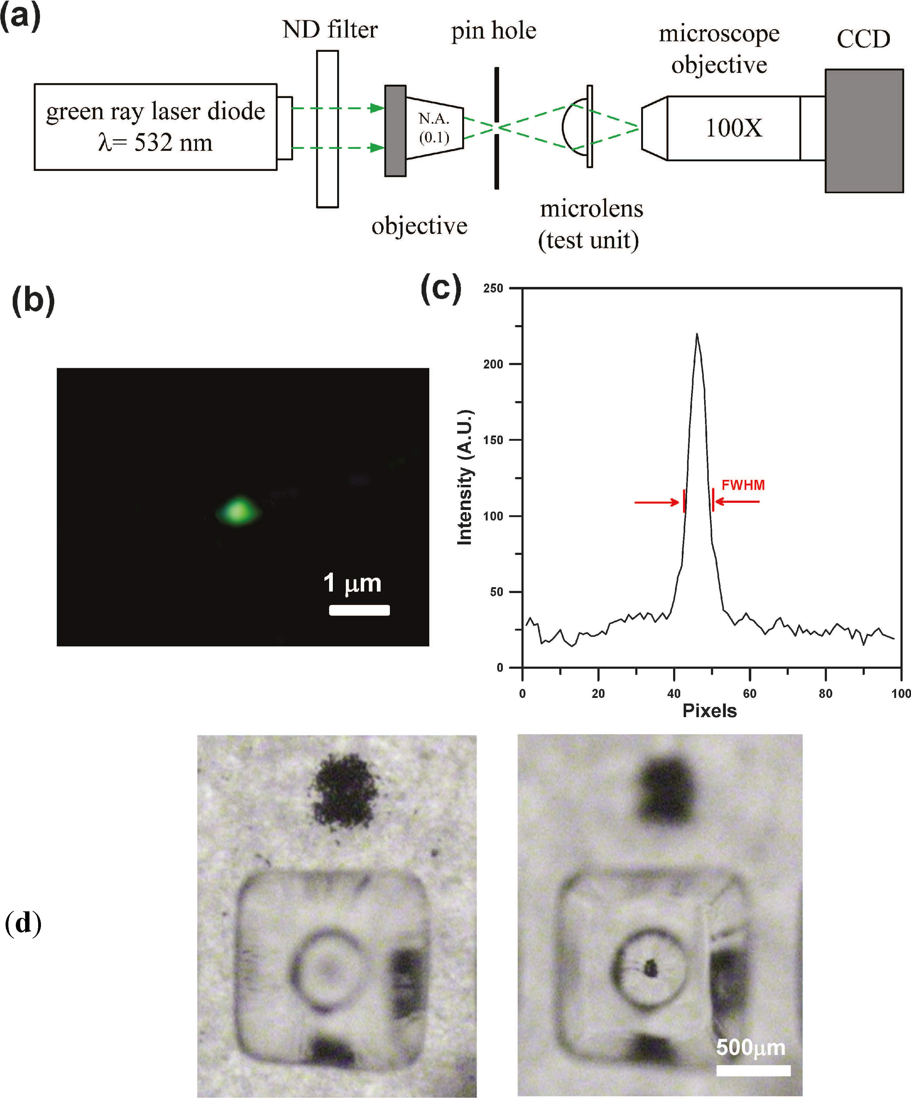
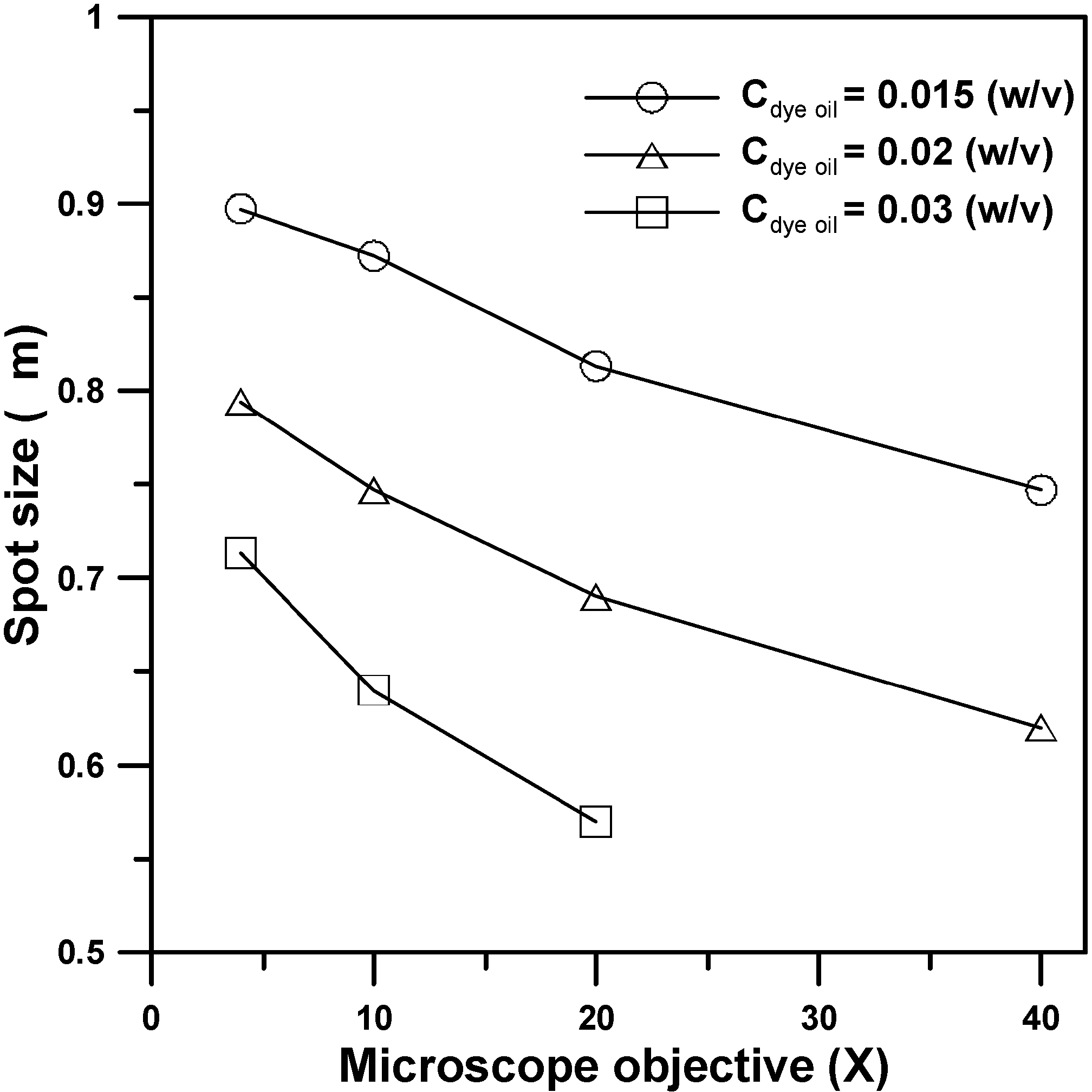
3.3. Spot Size Measurements of the Produced Microlens Structures

An optical system shown in Figure 6a was set up to carry out spot size measurements. A 532 nm laser diode with a power of 15 mW was used as the light source. In this system, a N.A. of the 0.1 (4×) microscope objective was used as a spatial filter and to ensure that the measurement would not introduce unwanted aberrations. Next, a pinhole (40 μm) was used to filter out redundant high-frequency noise. The light was directed to the testing microlens structure produced by EFM-3D mask. The CCD (WAT-221 S, Watec Inc., Orangeburg, NY, USA) equipped with a 100× magnification long-working distance lens was used to observe the spot size of laser beam. Image processing software was used to calculate the pixels of the optical energy distribution and to analyze the full width at half maximum (FWHM) of the spot size. Figure 6b,c show the image and the intensity distribution of the focus spot for the testing microlens structure produced by using 4× objectives and the EFM-3D mask filled with dye oil at Cdye oil = 0.03 (w/v). The focus spot size (FWHM) of the produced microlens structure is 0.72 μm. Figure 6d shows the images of a black ink dots which was observed by directly focusing the CCD on the paper (left) or through the produced microlens structure (right).
Figure 6. (a) Schematic illustrating an optical system set up to carry out spot size measurements. (b) The image and (c) the intensity distribution of the focus spot for the testing microlens structure produced by using 4× objectives and the EFM-3D mask filled with dye oil at Cdye oil = 0.03 (w/v). (d) The images of a black ink dots observed by directly focusing the CCD on the paper (left) or through the produced microlens structure (right).
Micromachines 05 00667 g006
Figure 7 shows the focus spot size of the produced microlens structures with respect to the objective magnifications from 4× to 40× for the EFM-3D mask filled with dye oil at Cdye oil = 0.015, 0.02, and 0.03 (w/v) and operated without applied voltages, respectively. For the EFM-3D mask filled with a fixed concentration (Cdye oil) of the dye oil, increasing the objective magnifications from 4× to 40× results in the decrease of the focus spot size of the microlens structures, which is contrary to the trend in the H/D of the microlens structures as show in Figure 5. The increase of the H/D of the microlens structure enables to decrease the focus spot sizes by changing the morphology of the microlens structure. The smallest focus spot size is 0.588 μm for the microlens structure produced by using 20× objective and the EFM-3D mask filled with the dye oil at Cdye oil = 0.03 (w/v). For using 40× objective, we found that the focus point was located inside the microlens structure, which was not suitable for the microlens application. Besides, when the concentration of dye oil (Cdye oil) is higher than 0.03 (w/v), most of the light intensity is absorbed prior to passing through the EFM-3D mask, which results in the failure of microlens formation.
Figure 7. The focus spot size of the produced microlens structures with respect to the objective magnifications from 4× to 40× for the EFM-3D mask filled with the dye oil at Cdye oil = 0.015, 0.02, and 0.03 (w/v) and operated without applied voltages, respectively.
Micromachines 05 00667 g007

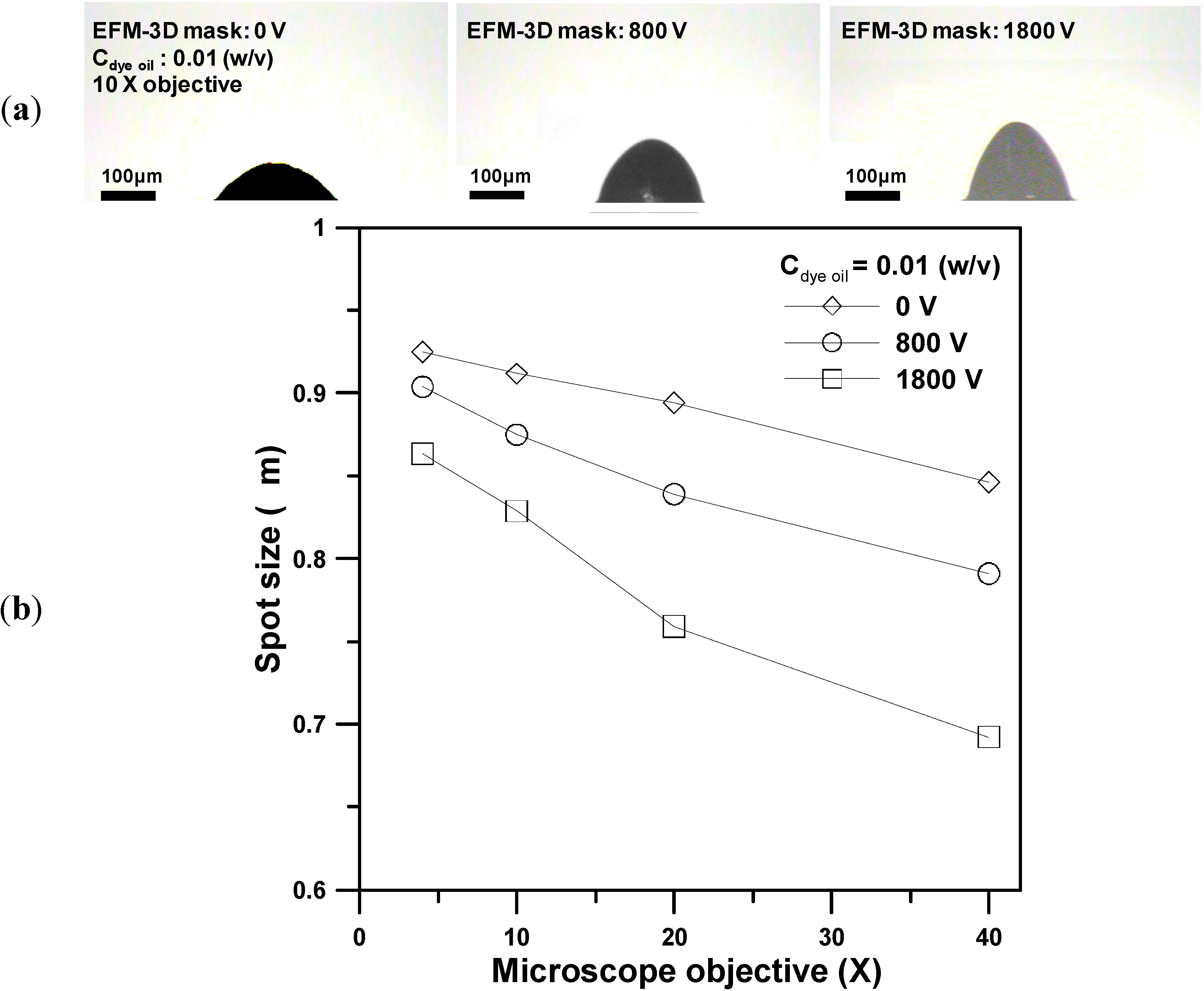
3.4. Adjust the EFM-3D Mask through Electrostatic Force to Produce Microlens Structures

Our previous work [14] have demonstrated the ability to dynamically adjust the EFM-3D mask through electrostatic force modulation. On application of a voltage across the EFM-3D mask, the induced electrostatic force causes the elastomer structures within the EFM-3D mask to change the morphology of the elastomer structures. When the voltage is removed, the elastomer structures return to the original arc-shaped morphology as shown in Figure 1. Here, we set the EFM-3D mask at the field-stop plane of the microscope, adjust the EFM-3D mask, and perform the SFL technique to produce the microlens structures.
Figure 8a shows images of the photopolymerized microlens produced by utilizing 10× objective for the EFM-3D mask filled with the dye oil at Cdye oil = 0.01 (w/v) and operated at 0 V, 800 V, and 1800 V, respectively. Changing the morphology of the elastomer structures within EFM-3D mask by controlling the applied voltages enables the dynamic adjustment of the intensity distribution that passes through the EFM-3D mask. This, in turn, changes the morphology of the corresponding microlens structures. Figure 8b shows the focus spot size of the produced microlens structures with respect to the objective magnifications from 4× to 40× for the EFM-3D mask filled at Cdye oil = 0.01 (w/v) and operated at 0 V, 800 V, and 1800 V, respectively. The results indicate that regardless of the voltage applied across the EFM-3D mask, increasing the objective magnifications from 4× to 40× results in the decrease of the focus spot size of the microlens structures. Increasing the applied voltages, while keeping the objective magnifications constant, also result in the decrease of the focus spot size of the produced microlens structures. Therefore, although the SFL system was equipped with a preset microscope objective and utilized the EFM-3D mask filled with a constant concentration of the dye oil, the morphology and optical properties of the photopolymerized microlens can be further modified by controlling the applied voltages for the EFM-3D mask.
Figure 8. (a) Images of the photopolymerized microlens structures produced by utilizing 10× objective for the EFM-3D mask filled with the dye oil at Cdye oil = 0.01 (w/v) and operated at 0 V, 800 V, and 1800 V, respectively. (b) The focus spot size of the produced microlens structures with respect to the objective magnifications from 4× to 40× at Cdye oil = 0.01 (w/v) and operated at 0 V, 800 V, and 1800 V, respectively.
Micromachines 05 00667 g008

4. Conclusions

In this work, we modified the SFL technique by utilizing an adjustable EFM-3D mask, where the EFM-3D mask was set at the field-stop plane of the microscope, to continuously fabricate microlens structures for high-throughput production. Microlens structures with variations in curvature and aperture can be produced by changing objective magnifications, controlling the morphology of the EFM-3D mask through electrostatic force modulation, and varying the concentration of UV-light absorption dyes. Furthermore, because the microlens arrays are allowed to flow downstream without problematic adhesion to the sidewalls, the fabrication method can be adapted for continuously high-throughput production. Although we demonstrated the ability to fabricate convex microlens structures in this study, our proposed method might be also capable to fabricate concave microlens structures by using the EFM-3D mask which is opposite to our current design. This EFM-3D mask contains a UV-absorbing elastomer structure doped with UV-light absorbing dyes to provide light attenuation and filled with a transparent index-matching oil. We believe that the modified STL utilizing adjustable EFM-3D masks allows one to fabricate microlens arrays in a fast, simple and high-throughput mode, which is conducive for massive production for application in micro-optical systems.

Acknowledgments

This work was partially supported by National Science Council, Taiwan, through the grant NSC 102-2221-E-019-015-MY2.

Author Contributions

Chia-Kai Lin performed the design, microfabrication, experiments, and analyzed the data. Shih-Hao Huang contributed to the original idea of this study, supervised the experiments and wrote the manuscript.

Conflicts of Interest

The authors declare no conflict of interest.

References

  1. Dendukuri, D.; Gu, S.S.; Pregibon, D.C.; Hatton, T.A.; Doyle, P.S. Stop-flow lithography in a microfluidic device. Lab Chip 2007, 7, 818–828. [Google Scholar] [CrossRef] [PubMed]
  2. Shepherd, R.F.; Panda, P.; Bao, Z.; Sandhage, K.H.; Hatton, T.A.; Lewis, J.A.; Doyle, P.S. Stop-flow lithography of colloidal, glass, and silicon microcomponents. Adv. Mater. 2008, 20, 1–6. [Google Scholar] [CrossRef]
  3. Suh, S.K.; Bong, K.W.; Hatton, T.A.; Doyle, P.S. Using stop-flow lithography to produce opaque microparticles: Synthesis and modeling. Langmuir 2011, 27, 13813–13819. [Google Scholar] [CrossRef] [PubMed]
  4. Suh, S.K.; Yuet, K.; Hwang, D.K.; Bong, K.W.; Doyle, P.S.; Hatton, T.A. Synthesis of nonspherical superparamagnetic Particles: In situ coprecipitation of magnetic nanoparticles in microgels prepared by stop-flow lithography. J. Am. Chem. Soc. 2012, 134, 7337–7343. [Google Scholar] [CrossRef] [PubMed]
  5. Baah, D.; Donnell, T.; Tigner, J.; Floyd-Smith, T. Stop flow lithography synthesis of non-spherical metal oxide particles. Particuology 2014, 14, 91–97. [Google Scholar] [CrossRef]
  6. Hwang, D.K.; Oakey, J.; Toner, M.; Arthur, J.A.; Anseth, K.S.; Lee, S.; Zeiger, A.; Van Vliet, K.J.; Doyle, P.S. Stop-flow lithography for the production of shape-evolving degradable microgel particles. J. Am. Chem. Soc. 2009, 131, 4499–4504. [Google Scholar] [CrossRef] [PubMed]
  7. Panda, P.; Ali, S.; Lo, E.; Chung, B.G.; Hatton, T.A.; Khademhosseini, A.; Doyle, P.S. Stop-flow lithography to generate cell-laden microgel particles. Lab Chip 2008, 8, 1056–1061. [Google Scholar] [CrossRef] [PubMed]
  8. Appleyard, D.C.; Chapin, S.C.; Srinivas, R.L.; Doyle, P.S. Bar-coded hydrogel microparticles for protein detection: Synthesis, assay and scanning. Nat. Protoc. 2011, 6, 1761–1774. [Google Scholar] [CrossRef] [PubMed]
  9. Pregibon, D.C.; Toner, M.; Doyle, P.S. Multifunctional encoded particles for high-throughput biomolecule analysis. Science 2007, 315, 1393–1396. [Google Scholar] [CrossRef] [PubMed]
  10. Chung, S.E.; Park, W.; Park, H.; Yu, K.; Park, N.; Kwon, S. Optofluidic maskless lithography system for real-time synthesis of photopolymerized microstructures in microfluidic channels. Appl. Phys. Lett. 2007, 91, 041106. [Google Scholar] [CrossRef]
  11. Lu, Y.; Chen, S.C. Direct write of microlens array using digital projection photopolymerization. Appl. Phys. Lett. 2008, 92, 041109. [Google Scholar] [CrossRef]
  12. Lee, S.A.; Chung, S.E.; Park, W.; Lee, S.H.; Kwon, S. Three-dimensional fabrication of heterogeneous microstructures using soft membrane deformation and optofluidic maskless lithography. Lab Chip 2009, 9, 1670–1675. [Google Scholar] [CrossRef] [PubMed]
  13. Hayashia, T.; Shibata, T.; Kawashima, T.; Makino, E.; Mineta, T.; Masuzawa, T. Photolithography system with liquid crystal display as active gray-tone mask for 3D structuring of photoresist. Sens. Actuators A Phys. 2008, 144, 381–388. [Google Scholar] [CrossRef]
  14. Huang, S.H.; Yu, Z.Y.; Lin, C.K.; Hung, K.Y. Dynamically adjustable three-dimensional gray masks operated by electrostatic force modulation for the fabrication of microlens arrays in microchannels. J Micro-Nanolith MEMS MOEMS 2010, 9, 043002. [Google Scholar]
  15. Dendukuri, D.; Panda, P.; Haghgooie, R.; Kim, J.M.; Hatton, T.A.; Doyle, P.S. Modeling of oxygen-inhibited free radical photopolymerization in a PDMS microfluidic device. Macromolecules 2008, 41, 8547–8556. [Google Scholar] [CrossRef]
  16. Hung, K.Y.; Fan, C.C.; Tseng, F.G.; Chen, Y.K. Design and fabrication of a copolymer aspheric bi-convex lens utilizing thermal energy and electrostatic force in a dynamic fluidic. Opt. Express 2010, 18, 6014–6023. [Google Scholar] [CrossRef] [PubMed]

