Article

Hydrothermal Engineering of Ferroelectric PZT Thin Films Tailoring Electrical and Ferroelectric Properties via TiO2 and SrTiO3 Interlayers for Advanced MEMS

1
Department of Power Mechanical Engineering, National Tsing Hua University, Hsinchu 30013, Taiwan
2
Institute of Nano Engineering and MicroSystems, National Tsing Hua University, Hsinchu 30013, Taiwan
*
Author to whom correspondence should be addressed.
Micromachines 2025, 16(8), 879; https://doi.org/10.3390/mi16080879
Submission received: 26 June 2025 / Revised: 18 July 2025 / Accepted: 27 July 2025 / Published: 29 July 2025
(This article belongs to the Special Issue Manufacturing and Application of Advanced Thin-Film-Based Device)

Abstract

This work presents an innovative hydrothermal approach for fabricating flexible piezoelectric PZT thin films on 20 μm titanium foil substrates using TiO2 and SrTiO3 (STO) interlayers. Three heterostructures (Ti/PZT, Ti/TiO2/PZT, and Ti/TiO2/STO/PZT) were synthesized to enable low-temperature growth and improve ferroelectric performance for advanced flexible MEMS. Characterizations including XRD, PFM, and P–E loop analysis evaluated crystallinity, piezoelectric coefficient d33, and polarization behavior. The results demonstrate that the multilayered Ti/TiO2/STO/PZT structure significantly enhances performance. XRD confirmed the STO buffer layer effectively reduces lattice mismatch with PZT to ~0.76%, promoting stable morphotropic phase boundary (MPB) composition formation. This optimized film exhibited superior piezoelectric and ferroelectric properties, with a high d33 of 113.42 pm/V, representing an ~8.65% increase over unbuffered Ti/PZT samples, and displayed more uniform domain behavior in PFM imaging. Impedance spectroscopy showed the lowest minimum impedance of 8.96 Ω at 10.19 MHz, indicating strong electromechanical coupling. Furthermore, I–V measurements demonstrated significantly suppressed leakage currents in the STO-buffered samples, with current levels ranging from 10−12 A to 10−9 A over ±3 V. This structure also showed excellent fatigue endurance through one million electrical cycles, confirming its mechanical and electrical stability. These findings highlight the potential of this hydrothermally engineered flexible heterostructure for high-performance actuators and sensors in advanced MEMS applications.

1. Introduction

Flexible piezoelectric thin films have attracted significant attention in recent years because of their promising applications in wearable electronics [1,2], soft robotics [3,4,5], biomedical sensors [6,7,8], pressure, strain and stretch sensors [9,10,11], and microelectromechanical systems (MEMS) [12,13]. Among various piezoelectric materials, lead zirconate titanate (PZT) has emerged as a highly researched topic owing to its excellent piezoelectric and ferroelectric properties, particularly near the morphotropic phase boundary composition [14,15,16]. PZT is a perovskite-structured material characterized by its structural stability and unique physical properties, such as a direct bandgap, high dielectric constant, and multifunctional characteristics including ferroelectricity, piezoelectricity, and thermoelectricity [17].
However, most high-performance PZT thin films reported in previous studies are typically deposited on rigid substrates such as silicon [18,19], platinum [20], strontium titanate (SrTiO3, STO) [21,22], fluorine-doped tin oxide (FTO) [23,24], or strontium ruthenate (SrRuO3, SRO), which limits their applicability in flexible devices. Therefore, this work focuses on developing PZT films suitable for integration into flexible substrates.
Various techniques have been used to fabricate piezoelectric thin films, including pulsed laser deposition (PLD) [25,26], atomic layer deposition (ALD) [27,28], sol–gel method [29,30], RF magnetron sputtering [31,32,33], and hydrothermal synthesis. While each method offers specific advantages, most require high temperatures or vacuum environments, making them less suitable for flexible substrates. In contrast, the hydrothermal method enables low-temperature film processing and is a highly promising approach for depositing high-quality piezoelectric films on flexible metal foils.
The hydrothermal method is a solution-based synthesis technique that operates at moderate temperatures (typically <250 °C) in sealed reactors (e.g., Teflon-lined autoclaves), enabling the deposition of highly crystalline and dense piezoelectric thin films on flexible metal substrates without the need for high-temperature annealing [34,35]. Previous studies have demonstrated its potential for depositing PZT on titanium substrates, including attempts to introduce TiO2 interfacial layers through annealing [36,37,38], but challenges remain in controlling lattice mismatch and achieving high crystalline quality.
Therefore, although the hydrothermal method enables direct low-temperature deposition of PZT on titanium substrates, challenges remain on metal foils, such as significant lattice mismatch, poor crystalline quality, unstable MPB composition, and high leakage current. Moreover, achieving stable and well-defined polarization–electric field (P–E) loop characteristics remains a critical challenge, especially for flexible PZT thin films on metal substrates. Stable PE loops are essential for reliable ferroelectric and piezoelectric device performance, yet are strongly influenced by interfacial quality, leakage current, and crystalline phase stability. Recent studies have emphasized the importance of engineering interfaces and buffer layers to improve P–E loop behavior and reduce hysteresis and leakage-related instabilities [39]. To address these challenges, this study proposes a multi-step hydrothermal synthesis strategy specifically designed for flexible titanium foils, which sequentially deposits TiO2 and SrTiO3 (STO) buffer layers to systematically reduce lattice mismatch, enhance dielectric isolation, and improve interfacial quality, ultimately achieving a stable MPB-phase composition in PZT films. The goal of this work is to demonstrate a feasible low-temperature process capable of producing high-quality flexible piezoelectric films with excellent crystallinity, electrical stability, and ferroelectric performance.
In the field of piezoelectric materials, titanium dioxide (TiO2) is widely utilized as an insulating and dielectric buffer layer because of its excellent insulating properties, high dielectric constant, and chemical stability. Among its polymorphs, the rutile phase is thermodynamically stable [40,41], featuring a more compact lattice than the anatase phase, with higher mechanical stability, a slightly higher dielectric constant, and a narrower bandgap (~3.0 eV vs. ~3.2 eV for anatase). Owing to these attributes, rutile TiO2 is suitable as an interfacial layer between metal substrates and functional materials, enhancing interfacial quality. To meet the design requirements of low-temperature flexible devices, we utilized a low-temperature hydrothermal process to form the TiO2 layer, avoiding high-temperature annealing. This TiO2 layer was further integrated with an STO layer to construct a heterostructure buffer for subsequent piezoelectric layer deposition.
STO, with a thermal expansion coefficient closely matched to common piezoelectric materials such as PZT, BNT, and PMN-PT, helps mitigate thermal stress and enhances film crystallinity and mechanical stability. Moreover, its low conductivity improves leakage current suppression during piezoelectric measurements, thereby enhancing electrical measurement accuracy [42]. As a non-conductive buffer layer, STO also serves as a favorable nucleation platform, improving surface morphology and polarization behavior of the piezoelectric films [43]. However, most applications of STO still rely on rigid single-crystal substrates (e.g., STO and LaAlO3), limiting its potential in flexible piezoelectric systems. This study seeks to overcome this limitation by directly synthesizing an STO crystalline layer on flexible titanium foils via hydrothermal processing, thereby forming an insulating buffer structure for subsequent piezoelectric film growth. The STO layer is expected to provide high dielectric isolation, reduce leakage currents caused by metallic substrates, and alleviate film stress from thermal mismatch, ultimately improving the electrical stability of devices. Furthermore, we investigate whether the high dielectric interface provided by the STO buffer layer can enhance polarization behavior and piezoelectric response of the subsequently deposited PZT layer.
In summary, this study employs a multi-step hydrothermal synthesis approach to fabricate three types of PZT heterostructures on flexible titanium foil substrates: Ti/PZT, Ti/TiO2/PZT, and Ti/TiO2/STO/PZT. We systematically investigate the effects of interfacial structures on structural, piezoelectric, and electrical properties, aiming to clarify whether the introduction of TiO2, and especially the STO buffer layer, can effectively enhance crystallinity, phase stability, and functional performance, thereby demonstrating the potential for developing high-performance flexible piezoelectric devices.

2. Experiment

Three types of lead zirconate titanate (PZT) thin film structures—Ti/PZT, Ti/titanium dioxide (TiO2)/PZT, and Ti/TiO2/strontium titanate (SrTiO3, STO)/PZT—were fabricated via a hydrothermal method to investigate the effects of heterogeneous interfacial layers on the structural, electrical, and piezoelectric properties of the films. Commercially pure titanium (Ti) foils with a thickness of 20 μm were used as substrates. Prior to the hydrothermal synthesis, the foils were ultrasonically cleaned in acetone, ethanol, and deionized water sequentially to remove surface contaminants.

2.1. Preparation of the TiO2 Film

The TiO2 buffer layer was synthesized via a hydrothermal process (Figure 1). The cleaned Ti substrates were placed in a Teflon-lined stainless-steel autoclave containing a precursor solution composed of 53.3 mL of titanium trichloride (12 wt%, in 15% HCl), 28.7 mL of hydrochloric acid (35 wt%), and 23.0 mL of deionized water [44,45,46]. The reaction was carried out at 180 °C for 6 h. After completion, the samples were removed, thoroughly rinsed with deionized water, and dried at room temperature to obtain a uniform TiO2 buffer layer.

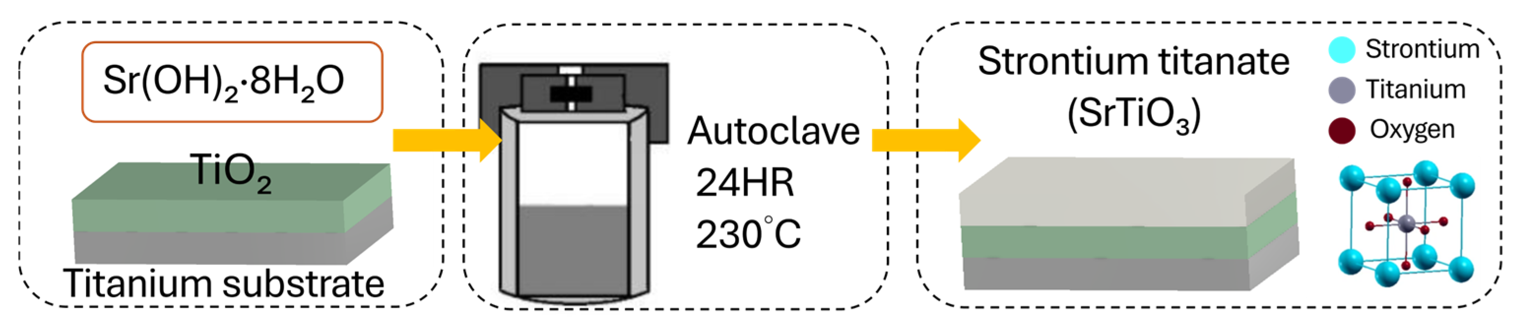
2.2. Preparation of the SrTiO3 Film

The STO seed layer was subsequently synthesized on the previously prepared Ti/TiO2 substrates [44]. The substrates were immersed in a hydrothermal solution prepared by dissolving 53.2 g of strontium hydroxide in 200 mL of deionized water (Figure 2). The reaction was performed in a Teflon-lined autoclave at 230 °C for 24 h [46]. After synthesis, the samples were rinsed with deionized water and dried at room temperature, resulting in a uniform STO interlayer.

2.3. Preparation of the PZT Film

After the preparation of the TiO2 and STO buffer layers, the PZT piezoelectric thin film was deposited via a two-step hydrothermal process. To achieve the morphotropic phase boundary (MPB) composition, which is known to exhibit superior piezoelectric performance, the precursor solution was formulated with a Zr/Ti atomic ratio of 52:48. Specifically, 17.1 g of zirconyl chloride (ZrOCl2·8H2O, 0.052 mol), 40.15 g of lead nitrate (Pb(NO3)2, 0.12 mol), and 3.83 g of titanium dioxide (TiO2, 0.048 mol) were dissolved in 250 mL of deionized water to obtain a Pb:Zr:Ti molar ratio of 1.2:0.52:0.48. A 20% excess of Pb was introduced to compensate for potential lead volatilization during the hydrothermal reaction.
The solution was stirred at 600 rpm for 1 h to ensure homogeneity and prevent premature precipitation. Subsequently, 89.1 g of potassium hydroxide (KOH, 1.58 mol) was added as a mineralizer, and the total volume was adjusted to 500 mL with deionized water. The solution was stirred for an additional hour to ensure dissolution and completion of the precursor reaction. The final precursor solution was designed to maintain an appropriate total metal ion concentration and alkalinity, both of which are critical for facilitating nucleation and stable formation of the perovskite PZT phase. This condition also helps prevent rapid precipitation or particle agglomeration, thereby promoting uniform crystallinity and high phase purity [47,48].
The prepared precursor solution and the Ti-based substrates (Ti, Ti/TiO2, or Ti/TiO2/STO) were sealed in a Teflon-lined autoclave and subjected to hydrothermal reaction at 180 °C for 24 h. After reaction and post-treatment, three types of PZT films—Ti/PZT, Ti/TiO2/PZT, and Ti/TiO2/STO/PZT—were successfully obtained. A schematic illustration of the multi-step hydrothermal fabrication process is shown in Figure 3, while photographs of the actual intermediate and final film samples are presented in Figure 4, highlighting the surface changes at each stage of the process.

2.4. Deposition of Electrodes for Electrical Characterization

After hydrothermal deposition of the PZT thin films, an Al electrode was deposited on the film surface by sputtering to serve as the top contact for electrical characterizations, including P–E hysteresis loop measurements, impedance analysis, and PFM imaging.
In addition, for preparing cross-sectional FIB–SEM samples, an Al coating was also applied before Pt deposition to improve surface conductivity and reduce charging effects. These conductive layers, including the Al layer and subsequently deposited Pt layer , were not part of the functional PZT device electrodes but were specifically applied for FIB–SEM sample preparation.

2.5. Preparation of FIB Cross-Section Samples

The preparation procedure for FIB cross-section samples is as follows. All steps were performed inside the FIB system using its built-in functions. Prior to milling, a two-step Pt protection layer was applied to the sample surface. First, an electron-beam-assisted Pt (e-beam Pt) deposition was carried out at 0° tilt to form a thin and uniform protective layer, minimizing ion beam damage. This was followed by ion-beam-assisted Pt (ion-beam Pt) deposition at a 52° tilt to increase the thickness of the protective layer, ensuring sufficient protection during bulk milling.
After Pt deposition, the sample was maintained at a 52° tilt to ensure the surface was perpendicular to the ion beam incidence. Bulk milling was performed with the Z-axis depth typically set to approximately 10 μm but adjustable as needed, using a bottom-to-top scan direction and the Si-multipass mode to improve cutting quality and reduce redeposition artifacts. Following initial coarse milling, low-current polishing was applied to further refine the cross-section surface smoothness and clarity.

3. Results and Discussion

In this section, we provide a systematic comparison of three PZT thin film structures—Ti/PZT, Ti/TiO2/PZT, and Ti/TiO2/STO/PZT—to understand how interfacial buffer layers influence structural quality, piezoelectric response, and electrical behavior. Our goal was not only to examine the final material performance but also to gain insight into how intermediate layers affect film growth dynamics and phase formation during hydrothermal synthesis. Accordingly, we employed a broad range of characterization techniques, including X-ray diffraction (XRD), focused ion beam scanning electron microscopy (FIB-SEM), energy-dispersive X-ray spectroscopy (EDX), piezoresponse force microscopy (PFM), polarization–electric field (P–E) hysteresis measurements, current–voltage (I–V) analysis, and impedance spectroscopy. Each method allowed us to observe a different aspect of material behavior, offering a more complete picture of how structural modifications translate into functional improvements. Particular emphasis is placed on the role of TiO2 and SrTiO3 (STO) interlayers in relieving lattice mismatch, stabilizing the morphotropic phase boundary (MPB) composition, and enhancing electromechanical coupling. In the following subsections, we discuss these findings in detail and compare the results across the three structures, highlighting trends that can inform the design of flexible, high-performance piezoelectric devices.
It should be noted that XRD and PFM imaging were performed as representative measurements on single samples to evaluate phase structure and domain morphology; these results are preliminary and do not capture statistical variation across multiple samples. In contrast, measurements such as impedance spectroscopy, FIB cross-section analysis, and P–E hysteresis loops were repeated on the same samples to verify consistency of trends, although only representative data are presented in this study for clarity.

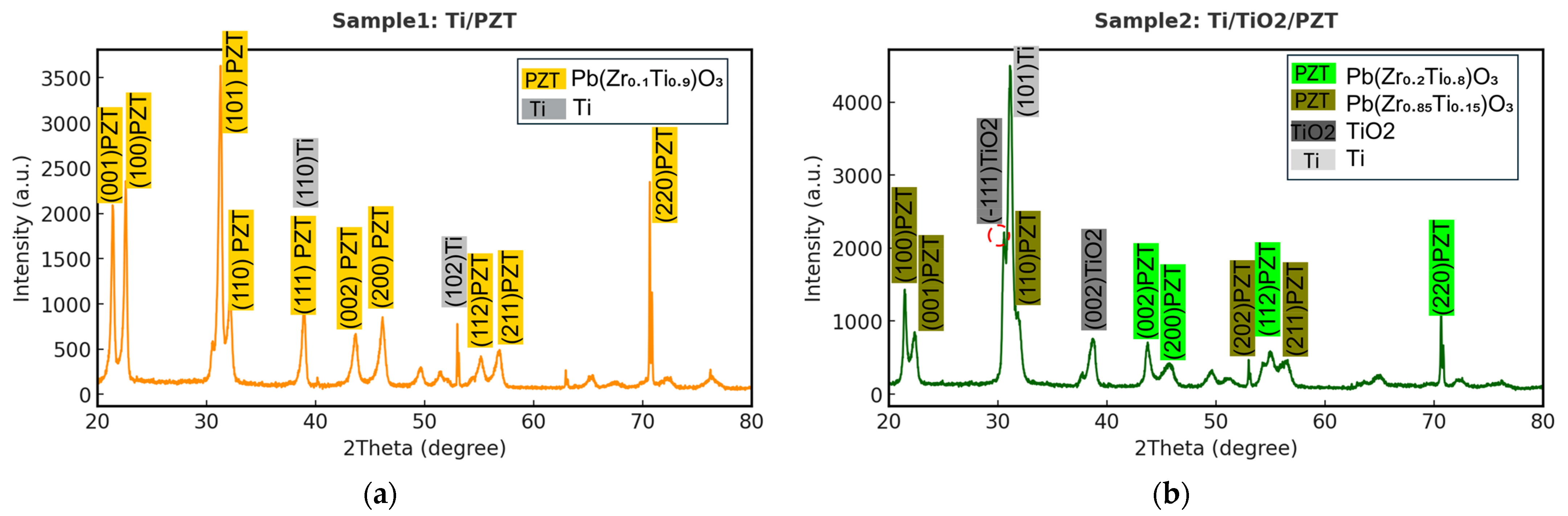
3.1. XRD Characterization and FWHM Evaluation

After the fabrication of the piezoelectric thin films, we performed material characterization on the PZT layers, focusing on the XRD patterns obtained from the three different fabrication processes. Figure 5a shows the XRD pattern of the Ti/PZT sample. As expected, the dominant diffraction peaks correspond to both Ti and PZT phases. The analysis was conducted using HighScore 3.0 software, where the peaks were matched with standard reference cards: PDF 04-007-2125 for titanium and PDF 04-012-8153 for the perovskite phase of PZT, specifically Pb(Zr0.1Ti0.9)O3. However, it is noteworthy that the PZT composition obtained in this process significantly deviates from the morphotropic phase boundary (MPB) region, where the optimal piezoelectric performance is typically achieved near the composition Pb(Zr0.52Ti0.48)O3. In contrast, the Ti/PZT sample exhibits a Ti-rich phase composition of Pb(Zr0.1Ti0.9)O3. This deviation is likely attributed to the considerable lattice mismatch between the Ti metal substrate and the PZT lattice. In the absence of any intermediate buffer layer (such as TiO2 or STO) to relieve the strain or modulate the lattice parameters, the high mismatch suppresses the crystallization of the ideal MPB composition and favors the formation of a Ti-rich phase, which exhibits better lattice compatibility with the underlying substrate [49]. According to the literature, the lattice parameters of the tetragonal MPB composition Pb(Zr0.52Ti0.48)O3 are approximately a = 3.935 Å and c = 4.144 Å, while those of hexagonal close-packed α-Ti are a = 2.951 Å and c = 4.683 Å (PDF 04-007-2125). The mismatch in the a-axis exceeds 25%, which can significantly influence nucleation behavior and phase formation, steering the growth toward a Ti-rich PZT phase such as Pb(Zr0.1Ti0.9)O3, which has lower formation energy and better structural compatibility at the interface (Table 1).
Consequently, the observed diffraction peaks are primarily attributed to the Ti metal phase and the non-MPB PbZr0.1Ti0.9O3 phase, with only minor contributions from PbZrO3. These results support the hypothesis that crystal growth in this sample is predominantly governed by lattice mismatch and interfacial strain with the substrate. The labeled peaks correspond to representative crystallographic planes, including PZT (001), (100), (110), (111), and Ti (110), (102), with Ti reflections shaded in gray.
Next, the XRD pattern of the Ti/TiO2/PZT bilayer structure was analyzed, as shown in Figure 5b. In this sample, a TiO2 buffer layer was first deposited on the titanium substrate via hydrothermal synthesis, followed by PZT growth. This process aimed to mitigate lattice mismatch at the interface and improve insulation quality.
According to HighScore database matching, the major diffraction peaks corresponded to rutile-phase TiO2 (PDF 01-074-9521), Ti-rich PZT (Pb(Zr0.2Ti0.8)O3) (PDF 01-070-4054), and the Ti substrate (PDF 01-071-3947). The strong rutile TiO2 peak confirms the successful formation of a well-crystallized buffer layer. The weaker Ti substrate signals suggest that most of the surface was effectively covered, while PZT peaks indicate both Ti-rich and Zr-rich compositions.
The PZT composition remained Ti-rich and did not approach the morphotropic phase boundary (MPB) composition of Pb(Zr0.52Ti0.48)O3, which is known for optimal piezoelectricity. Although the rutile TiO2 buffer partially reduced the mismatch, it was insufficient to stabilize the MPB phase. Rutile TiO2 has lattice constants of a = 4.593 Å, c = 2.959 Å (PDF 01-074-9521), while MPB-phase PZT has a = 3.935 Å, c = 4.144 Å—yielding an a-axis mismatch of ~16.7%. While rutile offers better compatibility than α-Ti (a = 2.951 Å), mismatch persists, influencing nucleation and promoting composition deviation and phase coexistence to relieve interfacial strain (Table 1 and Table 2).
In addition to dominant peaks from rutile TiO2 and PZT, trace signals (Pb(Zr0.4Ti0.6)O3) and (Pb(Zr0.85Ti0.15)O3) were also detected. Identified peaks include PZT (001), (100), (110), (111), rutile TiO2 (−111), and Ti (101). These results indicate that while rutile TiO2 provides partial lattice regulation, a more compatible buffer such as SrTiO3 (STO)—discussed next—may further improve phase purity and compositional stability.
Finally, the XRD pattern of the Ti/TiO2/STO/PZT multilayer sample was analyzed, as shown in Figure 5c. In this process, a TiO2 interlayer was first deposited on the titanium substrate via hydrothermal synthesis, followed by the growth of a SrTiO3 (STO) seed layer on the TiO2 surface, and finally, the deposition of the PZT film. This multilayer design aimed to sequentially reduce the lattice mismatch at each interface and minimize strain accumulation between the PZT and the metallic substrate, thereby facilitating the stable formation of a morphotropic phase boundary (MPB) PZT structure. As shown in Figure 5c, the diffraction peaks were matched with database references: STO was identified by PDF 04-011-7249, and the MPB-phase PZT composition Pb(Zr0.52Ti0.48)O3 corresponded to PDF 04-011-8849. The latter exhibited dominant intensity, indicating it as the primary phase of this sample. Only weak peaks from the Ti substrate (PDF 04-008-1385) and rutile-phase TiO2 (PDF 01-070-6826) were detected, suggesting that the substrate was well covered by the overlying STO and PZT layers, and that good crystallinity and surface coverage were achieved.
Compared with Sample 1 (Ti/PZT) and Sample 2 (Ti/TiO2/PZT), Sample 3 (Ti/TiO2/STO/PZT) exhibited a well-defined MPB composition with minimal compositional deviation, indicating no observable shift toward Ti-rich or Zr-rich phases. This confirms the effective role of the STO buffer layer in improving lattice compatibility and providing favorable nucleation conditions. The MPB PZT phase typically exhibits lattice constants of a = 3.935 Å and c = 4.144 Å, while cubic STO has a lattice constant of a = 3.905 Å (PDF 04-011-7249), resulting in an a-axis mismatch of only ~0.76%—significantly smaller than the ~25% mismatch between Ti and PZT discussed earlier. This improved lattice matching is expected to relieve interfacial strain and enhance the crystallinity and phase purity of the PZT film (Table 3). In Figure 5c, prominent peaks were observed for STO (110) at 32.313° with 100% intensity and (200) at 46.346° with 36% relative intensity, as well as for PZT (101) at 31.06° with 100% intensity and (100) at 21.825° with 30% intensity. These results verify that the hydrothermal growth of TiO2/STO/PZT multilayers can effectively buffer lattice mismatches step-by-step and promote the formation of MPB-phase PZT. Therefore, this process structure shows strong potential as an integrated fabrication route for high-performance flexible piezoelectric PZT devices.
To further compare the crystal structures, the XRD patterns of the three samples were overlaid, as shown in Figure 5d. Four distinct diffraction regions—30–34°, 38–41°, 44–48°, and 54–58°—revealed structural differences among the fabrication processes. In the 30–34° range, the main diffraction peak corresponds to the (101) plane of PZT. The Ti/TiO2/PZT sample exhibited the highest peak intensity in this region, suggesting that the TiO2 buffer layer effectively promotes preferential growth of PZT along the (101) orientation. However, after incorporating the STO layer, the PZT crystal structure tended to reorient toward other directions, resulting in a marked decrease in (101) peak intensity.
In the 38–41° range, the diffraction peaks likely arise from overlapping contributions of PZT (111) and Ti (110). A stronger signal was observed in the Ti/PZT sample, indicating a more prominent influence of the titanium substrate on the diffraction signal. The stepwise inclusion of TiO2 and STO effectively suppressed this interference and altered the PZT growth orientation, leading to a gradual reduction in peak intensity. In the 44–48° region, the peaks primarily correspond to PZT (002), (200), and TiO2 (002). The Ti/TiO2/PZT sample displayed two distinct peaks in this region, likely because of overlapping crystallographic planes, indicating a tendency toward oriented crystallization. In contrast, the introduction of STO led to broader, less intense peaks, suggesting a more uniform distribution of crystal orientations. In the 54–58° range, the peaks are associated with higher-order planes of PZT (112), (211), and the STO (211) reflection. Only the Ti/TiO2/STO/PZT sample exhibited a sharp and well-defined peak in this region, implying that the STO buffer layer provides a favorable lattice template that facilitates the aligned growth of PZT crystals along specific directions, resulting in enhanced crystallinity.
Although TiO2 and STO constitute a heteroepitaxial structure, previous studies have reported that STO can nucleate and grow stably on rutile-phase TiO2 under appropriate conditions, particularly during hydrothermal synthesis [50,51]. This is attributed to the sufficient ionic diffusion and slow growth rate characteristic of the hydrothermal process, which facilitates lattice accommodation and orientation selection. As a result, oriented polycrystalline structures can form even under moderate lattice mismatch. Moreover, STO, as a perovskite-structured material, possesses high structural tolerance, making it a suitable intermediate layer for heteroepitaxial growth.
Overall, the TiO2 interlayer slightly improves initial nucleation quality, but its effect on final crystal orientation remains limited. In contrast, the STO buffer layer further enhances crystal alignment and orientation selectivity, leading to improved structural properties of the PZT thin films.
We further analyzed the full width at half maximum (FWHM) of the XRD peaks, a key parameter reflecting crystallinity, grain size, and microstrain. The crystallite size was estimated using the Scherrer equation:
D = 0.94 λ β cos θ
where D is the crystallite size, λ is the X-ray wavelength (1.5406 Å for Cu Kα), β is the FWHM of the selected peak (in radians), and θ is the Bragg angle (half of the 2θ value).
For each sample, the most intense diffraction peak in the 30–35° range was selected for analysis. The average crystallite sizes for the three structures—Ti/PZT, Ti/TiO2/PZT, and Ti/TiO2/STO/PZT—were calculated to be 224.9 nm, 158.1 nm, and 117.7 nm, respectively, as summarized in Table 4. These values fall within the typical range reported for PZT films synthesized via hydrothermal methods (80–250 nm), consistent with low-temperature crystal growth characteristics.
Interestingly, a gradual decrease in crystallite size was observed with increasing buffer layer complexity. This trend may be attributed to enhanced lattice compatibility and strain modulation at the interface induced by TiO2 and STO seed layers, which can increase nucleation density and suppress grain coalescence. In particular, the STO layer appears to promote finer crystallite formation by effectively limiting grain growth. These results demonstrate that substrate structure significantly influences the crystallographic and microstructural evolution of PZT films during hydrothermal deposition.

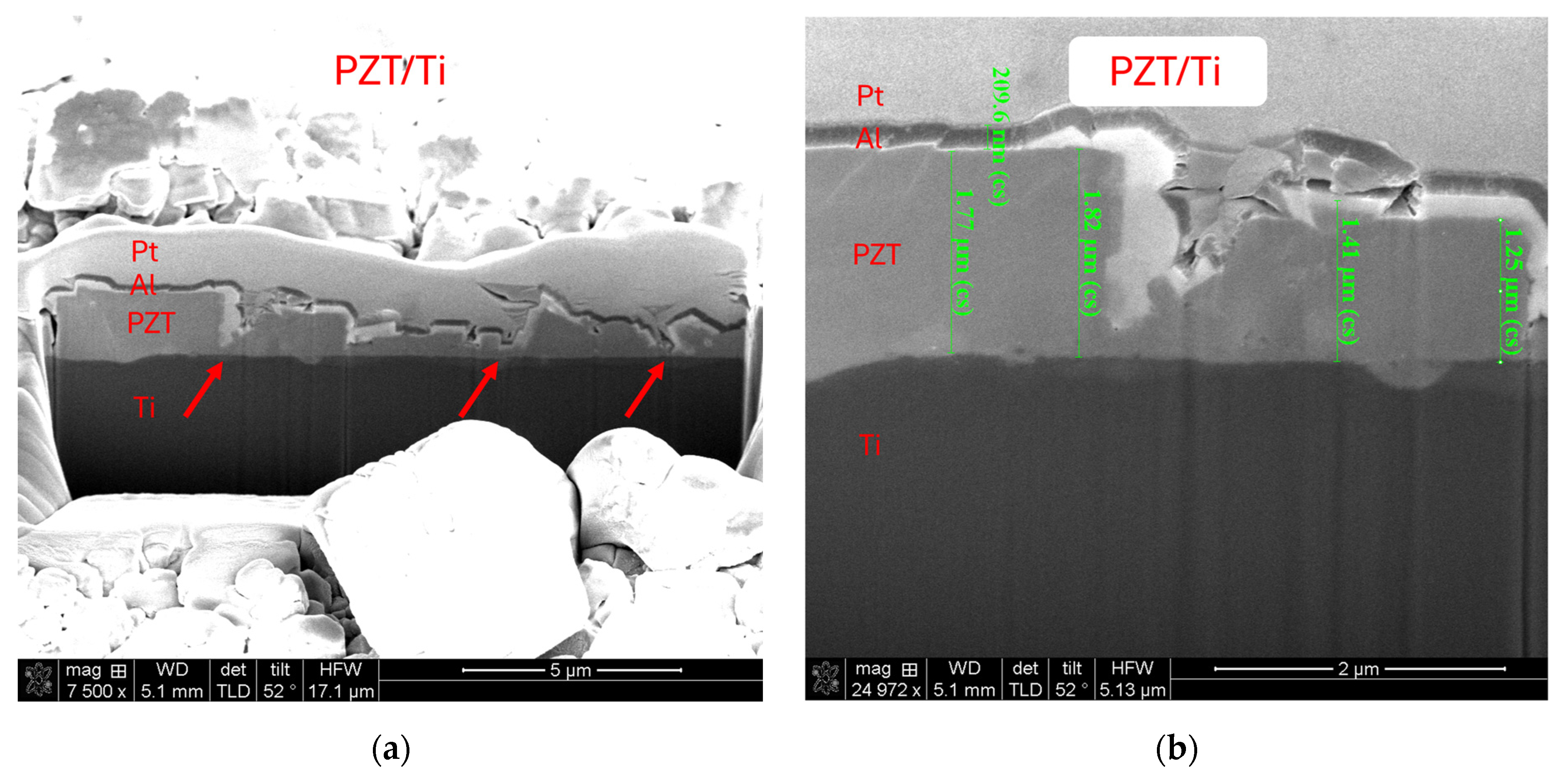
3.2. FIB Cross-Section and EDX Elemental Analysis

Cross-sectional observations of the PZT thin films were conducted using focused ion beam (FIB) microscopy to evaluate the film thickness, growth morphology, surface smoothness, and interfacial adhesion across the three different fabrication processes.
Figure 6a shows the FIB cross-section of the PZT film directly deposited onto the Ti substrate without any surface pretreatment (Ti/PZT), while Figure 6b presents a magnified view of the same sample, highlighting the local morphology and indicating the film thickness. In this sample, the PZT layer exhibits irregular and jagged features because of the large grain size and misoriented crystal growth. Significant recesses can be observed at the red arrows in Figure 6a, indicating non-uniform vertical growth and poor film flatness. This result highlights the challenges in achieving a uniform and dense PZT layer with the direct hydrothermal growth method on bare Ti, motivating the introduction of intermediate layers.
Figure 6c shows the cross-sectional morphology of the Ti/TiO2/PZT structure, where a TiO2 layer was first grown on the Ti substrate via hydrothermal synthesis prior to PZT deposition. Figure 6d presents a magnified view of the same sample, highlighting the local morphology and indicating the film thickness. Compared with the Ti/PZT sample, the film quality shows a slight improvement in terms of smoothness. However, jagged features and thickness variations are still evident. The TiO2 layer in particular displays a bubble-like morphology, suggesting a non-dense structure. The electrical insulation and leakage characteristics of this layer will be discussed in subsequent sections.
Figure 6e,g present FIB cross-sectional images of the Ti/TiO2/STO/PZT structure, where a thin STO seed layer was introduced between the TiO2 and PZT layers. Figure 6f and 6h show magnified views of Figure 6e,g, respectively, highlighting the local morphology and indicating the film thickness. This configuration results in a significantly more uniform TiO2 layer with a smoother interface. The overlying STO and PZT layers form a distinct multilayer architecture. Notably, the PZT film grown under this condition demonstrates improved morphological uniformity compared with the other two processes. Although minor surface undulations remain, the film exhibits a generally flatter and more continuous structure, leading to a more uniform thickness throughout the cross-section.
To verify whether the composition of the intermediate layers aligns with the intended design, energy-dispersive X-ray spectroscopy (EDX) was employed for compositional analysis. The primary objective was to confirm the elemental distribution within each layer and to evaluate the atomic ratio of the PZT layer. This study aims to synthesize lead zirconate titanate (Pb(Zr0.52Ti0.48)O3) thin films near the morphotropic phase boundary (MPB), which corresponds to an ideal atomic ratio of Pb:Zr:Ti:O ≈ 1:0.52:0.48:3. Given the lower sensitivity of EDX toward light elements such as oxygen and the semi-quantitative nature of the technique, the analysis focuses on the relative ratios of Pb, Zr, and Ti to assess the proximity of the film composition to the designed MPB target.
The first EDX measurement was conducted on the PZT layer of the Ti/PZT sample, as shown in Figure 7a The spectrum reveals Pb as the dominant element (44.99 wt%), followed by Ti (41.81 wt%) and O (9.57 wt%), while Zr accounts for only 3.63 wt%. This result indicates that the hydrothermally grown PZT film in this process is Ti-rich, with a notably low Zr content. This discrepancy may stem from the lack of pretreatment on the Ti substrate, making it difficult to form the desired MPB phase. It is likely that only Ti-rich PZT phases were successfully deposited. Additionally, the precursor solution was intentionally formulated with a 1.2× excess of Pb to compensate for potential volatilization losses, and it is possible that the Zr precursor exhibited lower reactivity during deposition.
In the Ti/TiO2/PZT process, the EDX result of the TiO2 layer (Figure 7b) shows a composition primarily consisting of Ti (75.61 wt%) and O (24.39 wt%), with no detectable peaks of Pb or Zr, confirming that the interlayer is composed of pure titanium dioxide as designed. In the same sample, the PZT layer (Figure 7c) exhibits Pb as the major element (50.22 wt%), with a significant Ti content (28.69 wt%) and notable Zr presence (10.79 wt%), while O accounts for 10.30 wt%. Compared with the Ti/PZT sample, the Pb content increased, the Ti content decreased, and the Zr content was notably higher. These findings suggest that the presence of a TiO2 interlayer can influence elemental incorporation during PZT film formation, helping to increase Zr content toward the targeted MPB composition, although the resulting film still remains Ti-rich overall.
In the Ti/TiO2/STO/PZT process, the EDX result of the TiO2 layer (Figure 8a) shows it is primarily composed of Ti (74.84 wt%) and O (25.16 wt%), with no detectable peaks of Pb or Zr, confirming the interlayer consists of pure titanium dioxide as designed.
For the STO layer (Figure 8b), the EDX spectrum reveals the presence of Sr (1.69 wt%), along with noticeable signals from Pb, Zr, and Ti elements typically associated with the adjacent PZT layer. This is because the STO interlayer is extremely thin, and the FIB-SEM EDX measurement is performed over a small but finite interaction volume rather than at an ideal point. As a result, signals from the surrounding PZT layer inevitably contribute to the detected spectrum, which also explains the relatively low Sr content observed. In the same sample, the PZT layer (Figure 8c) shows Pb as the major element (38.24 wt%), with Ti (35.17 wt%), Zr (17.06 wt%), and O (9.53 wt%). Compared with the other two processes, this sample demonstrates a higher Zr content, suggesting that the inclusion of both TiO2 and STO interlayers can promote the incorporation of Zr during hydrothermal PZT growth and move the composition closer to the desired MPB target.
In summary, all three samples exhibit the essential elements of PZT (Pb, Zr, and Ti), but with varying ratios depending on the fabrication process. These variations can be attributed to differences in hydrothermal growth conditions, interlayer effects, lattice compatibility, and ion diffusion or crystallization behavior. Such insights provide a foundation for further process optimization aimed at achieving compositionally controlled and high-performance PZT thin films.

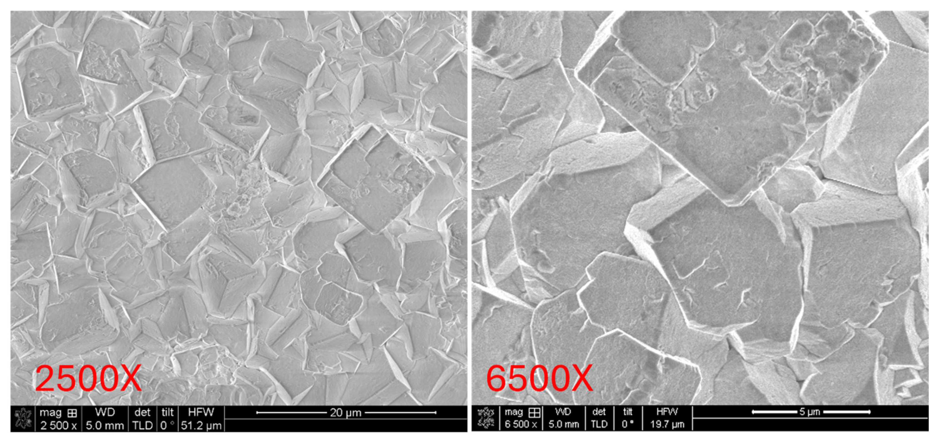
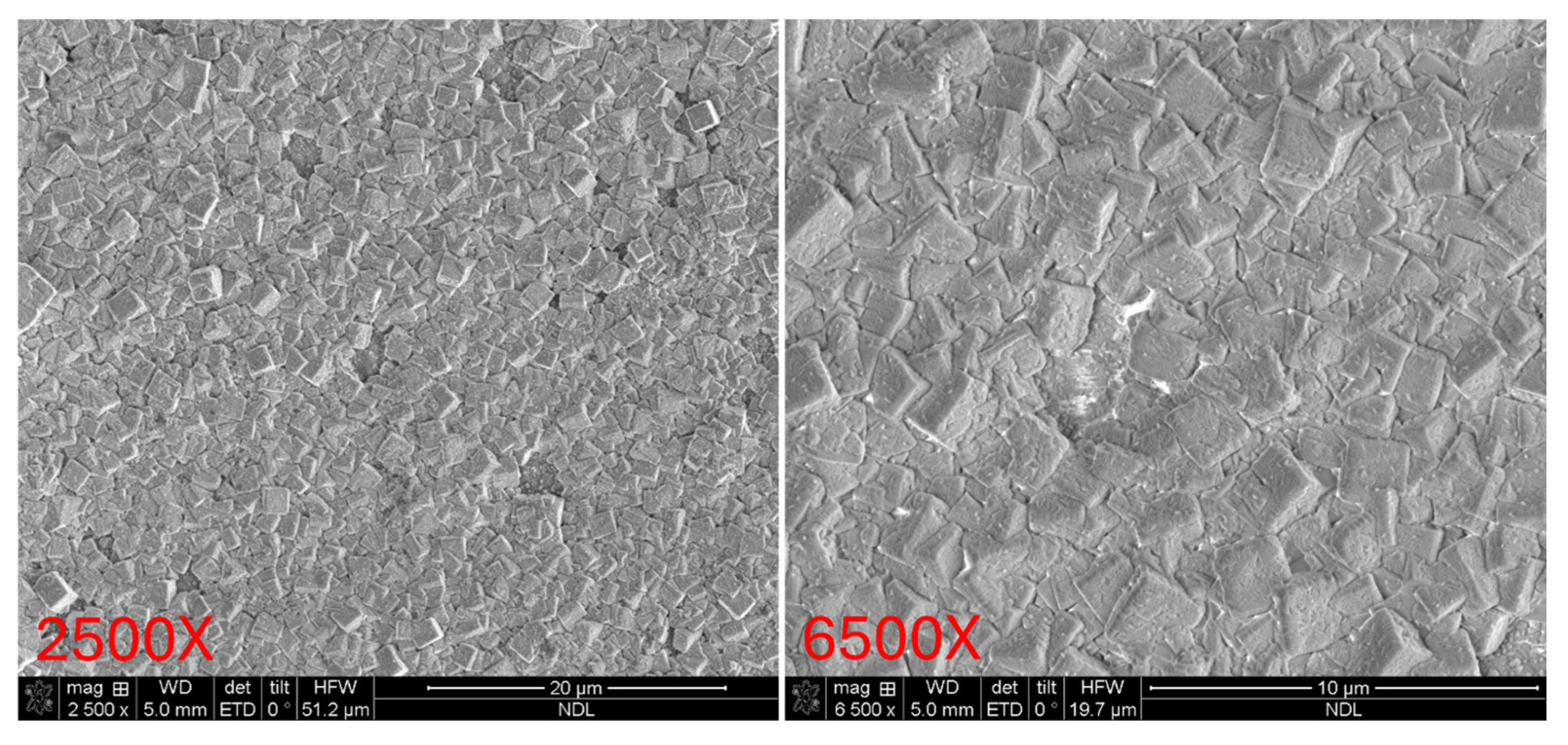
3.3. SEM Surface Morphology Analysis

Subsequently, the surface morphologies of the three PZT samples were examined using field-emission scanning electron microscopy (FE-SEM), as shown in Figure 9, Figure 10 and Figure 11 Each sample was observed at magnifications of 2500× and 6500× to enable comparison of surface microstructure across both large and fine observation scales. These magnifications allow for detailed evaluation of surface crystallinity, grain distribution, and morphological uniformity.
According to previous studies, surface roughness and thickness variation in piezoelectric thin films can lead to non-uniform and unpredictable piezoelectric responses, in contrast to the consistent behavior observed in flat, uniform films [52]. Defective regions in the film may exhibit degraded performance, and areas with reduced thickness are more prone to dielectric breakdown or short-circuiting under applied electric fields. These issues underscore the need for structural optimization and uniform film growth.
Figure 9 presents the SEM images of the Ti/PZT sample. Large grains with clearly defined boundaries can be observed, along with significant surface roughness and visible cracks. These features indicate non-uniform film growth, potentially associated with localized stress concentration during crystallization, which may result in grain fracture and discontinuous interfaces. Then, Figure 10 shows the Ti/TiO2/PZT sample. Compared with Ti/PZT, the grain size is reduced, suggesting that the TiO2 buffer layer partially inhibits excessive grain growth. However, the grain shapes appear irregular, and surface defects and height variation are still present in certain regions. This suggests that while the TiO2 layer provides some improvement, it is insufficient to fully suppress surface roughness or enhance morphological uniformity. In contrast, Figure 11 displays the surface morphology of the Ti/TiO2/STO/PZT sample. This sample demonstrates a highly uniform distribution of fine grains, with no significant cracks or surface undulations. The film exhibits a dense and consistent surface morphology. These results indicate that the STO seed layer offers favorable lattice matching and stress buffering capabilities, which promote homogeneous grain growth and significantly enhance the surface flatness of the PZT film.

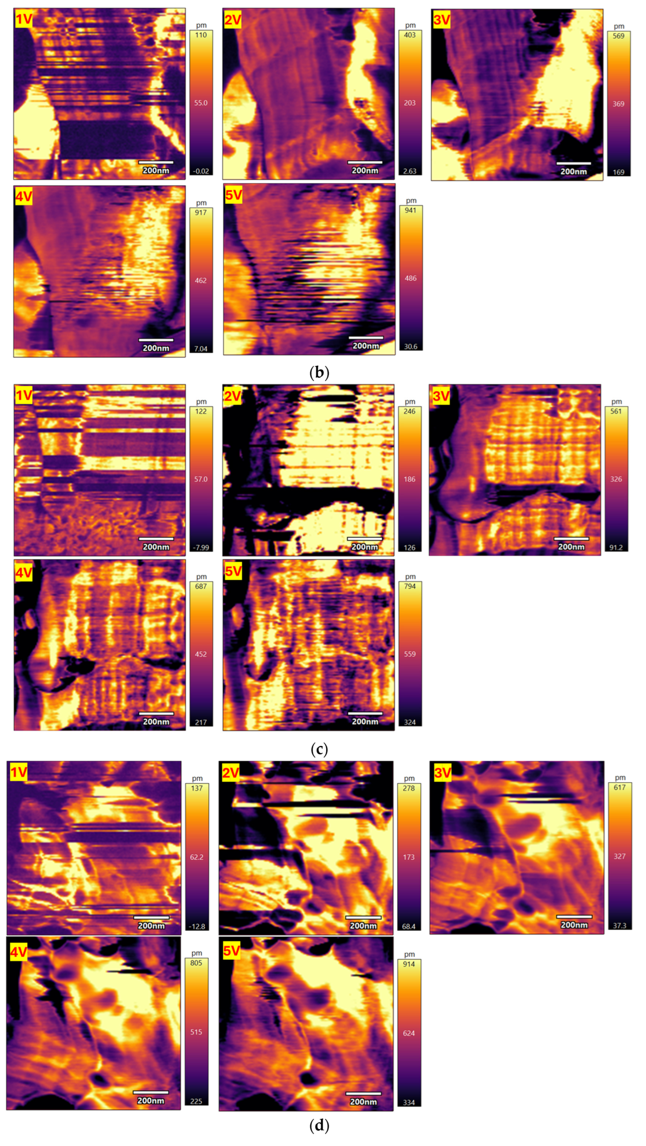
3.4. PFM Characterization of d33 Response

The d33 of the three PZT samples was measured using a Cypher S AFM Microscope (Asylum Research, Santa Barbara, CA, USA) equipped with a high-speed scanning system. The measurements were conducted in DART SS-PFM mode using a conductive probe (model: ASYELEC-02), which operates at a cantilever resonance frequency between 800 kHz and 900 kHz.
The measured d33 values are summarized in Table 5. In the low voltage range of 1–3 V, the Ti/TiO2/STO/PZT structure exhibited a relatively lower piezoelectric response, with d33 values comparable to the other two samples. This behavior is attributed to the incomplete domain switching within the ferroelectric film and the possibility of a higher activation field associated with the multilayer structure. Additionally, due to the nonlinear nature of piezoelectric polarization, a sufficient driving voltage is required before any significant enhancement in response can be observed—particularly when comparing complex multilayer systems to simpler structures.
However, upon increasing the applied voltage to 4–5 V, the Ti/TiO2/STO/PZT structure demonstrated a significantly higher piezoelectric response than the other two configurations, indicating superior polarization behavior under higher electric fields. This improvement supports the conclusion that the inclusion of the STO buffer layer contributes positively by enhancing strain transfer, reducing interfacial stress and lattice mismatch, and promoting the formation of MPB-phase PZT.
The corresponding displacement–voltage trend is plotted in Figure 12a. After calculating the weighted average of d33, the values were found to be 104.92 pm/V for Ti/PZT, 105.92 pm/V for Ti/TiO2/PZT, and 113.42 pm/V for Ti/TiO2/STO/PZT. The results indicate that the first two structures show similar d33 performance, while the addition of the STO layer leads to enhancements of 8.65% and 7.62% compared with the Ti/PZT and Ti/TiO2/PZT samples, respectively.
The d33 response maps shown in Figure 12b–d reveal clear differences in piezoelectric performance among the three processing structures. For the Ti/PZT sample in Figure 12b, the response distribution exhibits distinct striped regions with low d33 values, indicating non-uniform piezoelectric behavior. This is likely due to increased interface defects, surface roughness observed in FIB cross-sections, internal strain inhomogeneities, and incomplete nucleation processes, all of which can disrupt domain alignment.
In contrast, the Ti/TiO2/PZT structure in Figure 12c shows a higher proportion of mid- to high-response regions, though striped features and local low-response zones remain. This improvement may be attributed to the TiO2 buffer layer enhancing surface smoothness and promoting better crystallographic orientation, though performance is still limited by residual lattice mismatch and interfacial stress between TiO2 and PZT.
The Ti/TiO2/STO/PZT structure in Figure 12d, however, displays the most uniform and extensive high-response regions, indicating superior polarization and more consistent d33 performance. This enhancement can be attributed to the STO buffer layer providing better lattice matching and interface quality, reducing dislocations, and stabilizing ferroelectric domain alignment.
Overall, the observed differences in the d33 color scale distribution across these PFM maps correlate closely with the different processing strategies, demonstrating that the inclusion of STO effectively improves both the piezoelectric response and its spatial uniformity in PZT thin films.
The effective piezoelectric coefficient (d33) measured from the Ti/TiO2/STO/PZT sample reached 113.42 pm/V, indicating superior piezoelectric performance among the tested structures. This value is comparable to those reported in the recent literature. For instance, Dagdeviren et al. summarized that most flexible PZT-based structures exhibit d33 values ranging from ~80 to 130 pm/V, with enhanced responses (~130 pm/V) achieved via wavy geometries and mechanical pre-straining [53]. Bhadwal et al. reviewed a wide range of piezoelectric nanogenerators, noting that typical flexible thin film systems often report d33 values between 60 and 120 pm/V depending on composition and substrate compatibility [54]. Ramesh et al. further emphasized that d33 values exceeding 100 pm/V are typically considered indicative of well-optimized piezoelectric systems [55]. In comparison, the d33 result of our STO-buffered sample (113.42 pm/V) not only meets but slightly surpasses the typical range, despite being synthesized via a low-temperature hydrothermal process on flexible titanium foil. This supports the effectiveness of the TiO2/STO buffer structure in enhancing polarization alignment and electromechanical coupling efficiency.

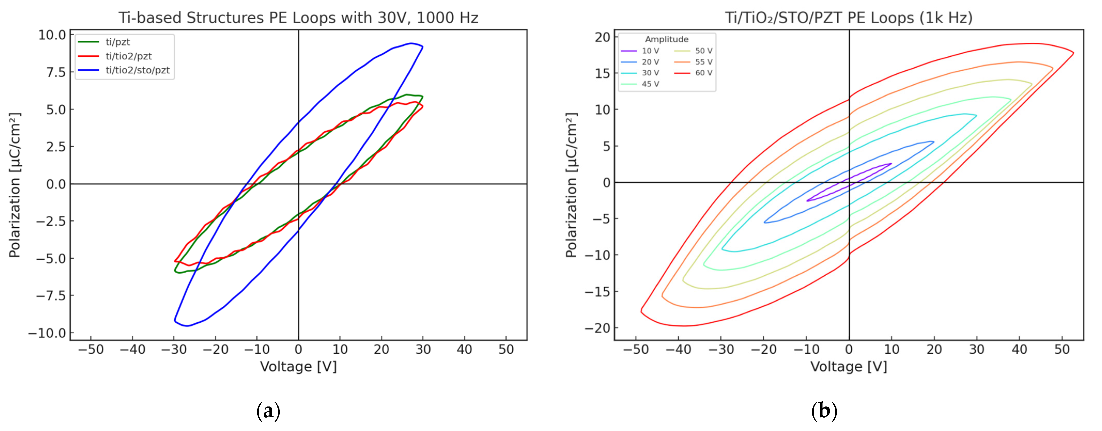
3.5. Ferroelectric P–E Loop Characterization

3.5.1. Comparative Analysis of P–E Loops for Different Film Structures

The ferroelectric properties of the PZT samples fabricated by the three different processes were evaluated using polarization–electric field (P–E) hysteresis loop measurements. The measurements were performed at a fixed frequency of 1000 Hz, with an applied electric field of 30 V. Figure 13a shows an overlaid comparison of the P–E curves for the Ti/PZT, Ti/TiO2/PZT, and Ti/TiO2/STO/PZT samples under identical testing conditions (30 V and 1000 Hz). The shape and symmetry of the hysteresis loops provide insight into the ferroelectric behavior and domain switching characteristics of each sample.
Of the three structures, the Ti/TiO2/STO/PZT sample exhibits the widest hysteresis loop and the highest polarization values, both in terms of saturation polarization (Ps) and remanent polarization (Pr). The Pr value reaches 4.084 μC/cm2, indicating enhanced domain switchability and improved polarization stability. This improvement can be attributed to the STO buffer layer, which facilitates better lattice matching and enhances interfacial electrical properties.
In contrast, the Ti/PZT and Ti/TiO2/PZT samples show more comparable behavior, with the latter exhibiting a slightly higher Pr of 2.228 μC/cm2, compared with 2.087 μC/cm2 for the Ti/PZT sample. This suggests that the TiO2 layer contributes moderately to polarization retention. However, the narrower hysteresis loop observed for this sample implies limited saturation polarization, indicating that its overall ferroelectric switching capability remains constrained.
Overall, the Pr and Ps values follow the trend: Ti/TiO2/STO/PZT > Ti/TiO2/PZT > Ti/PZT. These results demonstrate that the incorporation of an STO buffer layer plays a critical role in enhancing the ferroelectric performance of multilayer heterostructures. This process is particularly advantageous for ferroelectric devices requiring high polarization responses and may be further applied to improve the performance of existing device platforms through structural and interfacial optimizations.
The P–E hysteresis behavior of the Ti/TiO2/STO/PZT structure was further investigated under varying applied voltages ranging from 10 V to 60 V at a fixed frequency of 1 kHz. As shown in Figure 13b, it was observed that the hysteresis loops gradually widened with increasing electric field, indicating a clear field-dependent enhancement of ferroelectric behavior. At low voltages (10–20 V), the P–E loops were relatively narrow and exhibited near-linear behavior, suggesting that polarization was not yet fully saturated. In this region, both the coercive field (Ec) and remanent polarization (Pr) values remained small.
As the applied voltage increased to 30–45 V, the loops began to display pronounced hysteresis, signifying progressive domain switching and a significant increase in polarization capability. At higher voltages (50–60 V), the loop area enlarged considerably, and both the saturation polarization (Ps) and Pr continued to rise, indicating that the PZT film approached or reached a saturated polarization state. Overall, the Ti/TiO2/STO/PZT structure exhibited strong electric-field responsiveness and well-defined saturation behavior. Even under high-voltage operation, the loops remained symmetric and stable, demonstrating the effectiveness of the STO buffer layer in enhancing interfacial electrical properties and polarization stability. These characteristics highlight the potential of this multilayer structure for future applications in actuators and non-volatile memory devices.
To further benchmark the ferroelectric performance of our sample, we compared the P–E hysteresis behavior of the Ti/TiO2/STO/PZT heterostructure with values reported in the recent literature. A review article noted that low-temperature processed PZT films on flexible or semiconductor-compatible substrates typically exhibit remanent polarization (Pr) values in the range of 10–20 µC/cm2 [56]. In comparison, our STO-buffered structure exhibited a remanent polarization (Pr) of approximately 13 µC/cm2 under high electric field conditions, as shown in Figure 13b. This result demonstrates that despite the low-temperature hydrothermal process, our heterostructure design achieves ferroelectric performance comparable to previously reported systems.

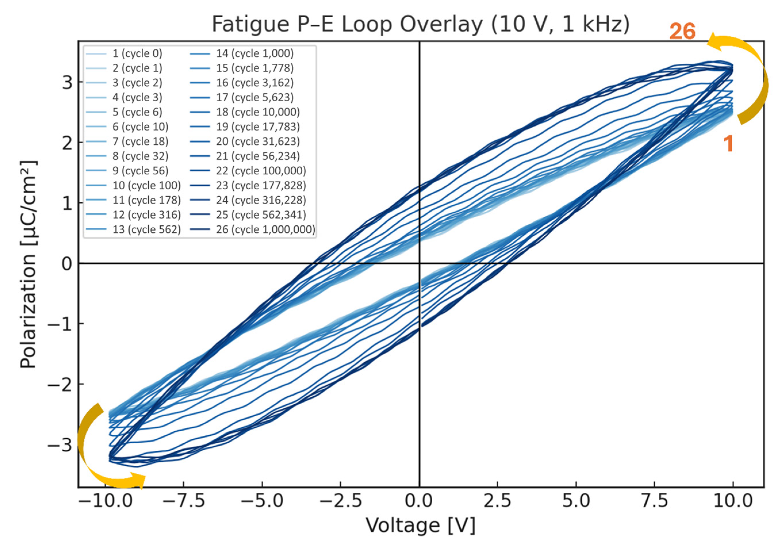
3.5.2. Ferroelectric Fatigue Behavior of STO-Based PZT Films

To evaluate the ferroelectric fatigue behavior of the Ti/TiO2/STO/PZT sample developed in this study, we conducted a fatigue test under controlled conditions. A bipolar sinusoidal voltage with an amplitude of ±10 V and a frequency of 1000 Hz was applied for a total of 106 cycles (1,000,000 cycles). To monitor the evolution of ferroelectric properties at different stages of fatigue, data points were collected on a logarithmic scale, with four measurement points per decade. A total of six decades were covered, resulting in 24 intermediate test points. Additionally, one initial (pre-fatigue) and one final (post-106 cycles) data point were included, yielding a total of 26 polarization–electric field (P–E) curves for fatigue analysis.
The corresponding cycle counts for each individual P–E curve are summarized in Table 6, where 26 discrete measurement points spanning from 0 to 1,000,000 cycles are indexed. These measurement points are selected logarithmically, ensuring a comprehensive evaluation of polarization evolution across all fatigue stages.
As shown in Figure 14, the 26 P–E curves reveal a clear trend of increasing remanent polarization (Pr), saturation polarization (Ps), and coercive field (Ec) with increasing cycle count. Notably, even after 106 cycles, the sample exhibited no signs of degradation or collapse in polarization behavior. On the contrary, the PZT film demonstrated enhanced polarization strength and electric field retention, indicating the occurrence of a polarization activation phenomenon during the fatigue process. This behavior can be attributed to the gradual alignment and stabilization of initially misaligned or weakly polarized ferroelectric domains under repeated electrical cycling. This domain evolution enhances net polarization, a process known as electrical cycling polarization treatment in ferroelectric materials.
While the primary objective of fatigue testing is typically to assess the material’s stability and degradation behavior under millions of electrical cycles, our findings suggest that before any catastrophic failure (e.g., polarization collapse, leakage, or dielectric breakdown) occurs, moderate electric field cycling can actually improve the material’s performance. Under the test conditions used in this study (±10 V, 1000 Hz, and 106 cycles), the Ti/TiO2/STO/PZT sample demonstrated excellent polarization stability and fatigue resistance, along with a notable performance enhancement effect. These results highlight the sample’s strong potential for applications in high-frequency actuators and piezoelectric devices, providing a solid foundation for future functional integration.

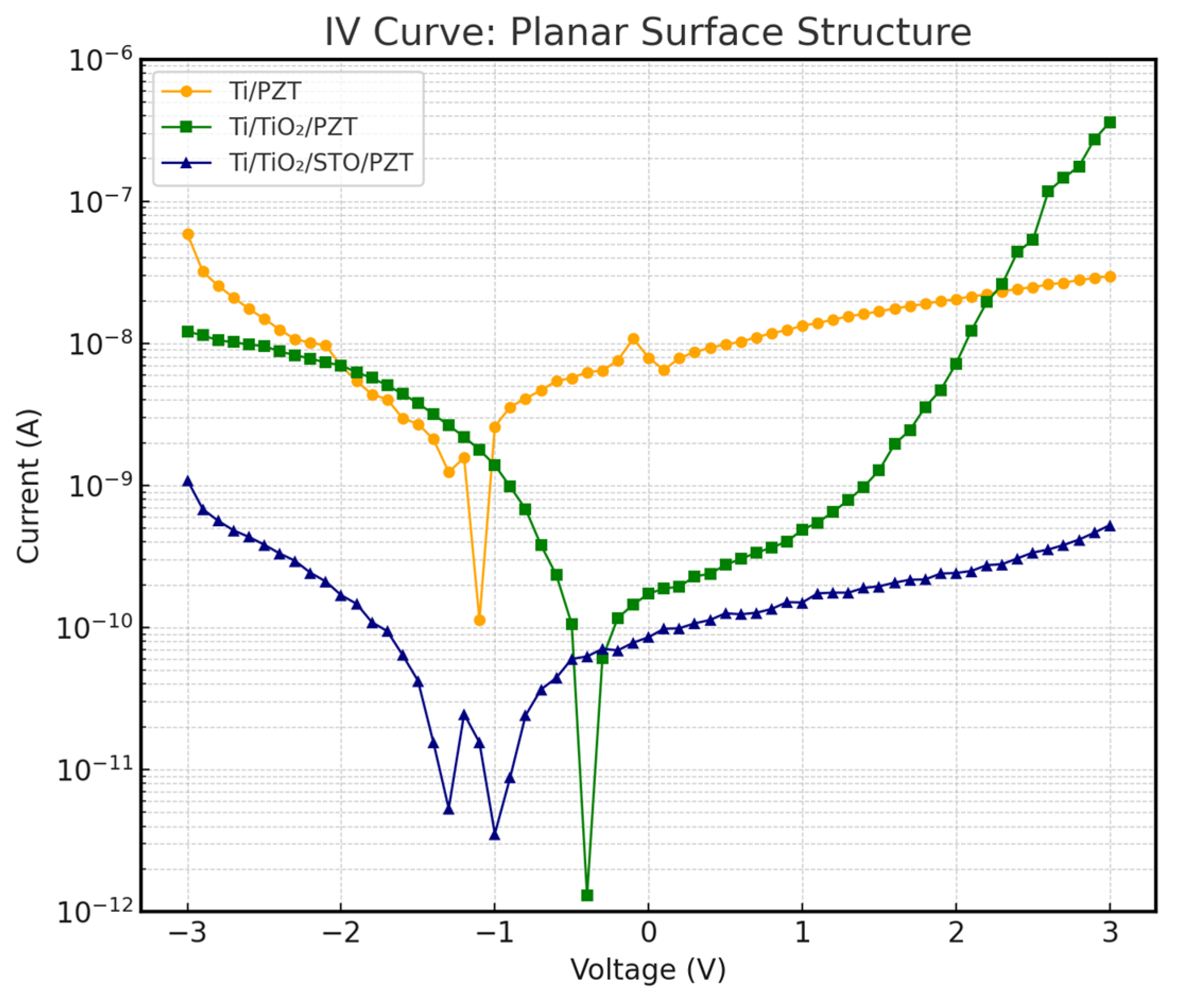
3.6. I–V Characteristics and Leakage Current Analysis

To further investigate the impact of different heterostructures on device insulation performance, current–voltage (I–V) measurements were conducted. In preparation for future device integration, we tested three PZT structures—Ti/PZT, Ti/TiO2/PZT, and Ti/TiO2/STO/PZT—on both flat and curved substrates, with the curved substrates having a curvature radius equivalent to a circular form with a 50 mm diameter. The I–V measurements effectively reflect the leakage current behavior under an applied DC voltage. Figure 15 and Figure 16 show the I–V characteristics of the three structures on flat and curved surfaces, respectively. The vertical axis represents current on a logarithmic scale, which enhances resolution in the low-current regime.
The results show that the Ti/TiO2/STO/PZT structure with an incorporated SrTiO3 (STO) buffer layer exhibited the best insulation behavior under both substrate conditions. Its leakage current remained consistently within the nanoampere range (10−9 A) across the entire voltage sweep, significantly lower than the values observed for the other two structures without STO. Remarkably, this excellent insulation was preserved even under curved deformation, with no noticeable current spikes, indicating strong mechanical adaptability and electrical stability.
In contrast, the Ti/PZT and Ti/TiO2/PZT samples demonstrated relatively poor insulation performance. Particularly under positive bias, leakage currents often increased into the 10−7 A range. This issue became even more pronounced on curved substrates, where higher leakage currents were observed. We speculate that the increased mechanical stress induced by bending may exacerbate defect conduction paths along grain boundaries or through localized film defects.
Overall, the incorporation of an STO buffer layer effectively suppressed leakage current and improved the structural resilience to mechanical curvature. To further contextualize our findings, we compared our measured leakage current values with those reported in recent studies. In our Ti/TiO2/STO/PZT structure, the leakage current remained within the range of 10−12 to 10−9 A under ±3 V bias. In contrast, Liu et al. [57] reported leakage currents on the order of 10−8 A for sol–gel-derived PZT films on mica substrates under similar voltage conditions, which may result from interface or grain boundary defects in their fabrication process. Yuan et al. [58] also demonstrated that the appropriate selection of bottom electrode materials could reduce leakage current to approximately 10−9 A. Compared with these references, our hydrothermally synthesized multilayer-buffered structure exhibits comparable or superior insulation performance, reinforcing the benefits of our dielectric buffer layer design in suppressing leakage paths and enhancing electrical reliability.

3.7. Impedance and Phase Angle Analysis

Impedance analysis was performed to evaluate and compare the electrical and electromechanical performance of PZT thin films fabricated via three different processes. The impedance and phase angle (θ) curves were measured for all samples using identical axis scaling for both impedance and phase. The frequency sweep ranged from 100 Hz to 50 MHz, with an applied AC voltage of 1 V and a high-resolution scan comprising 1600 points.
We first analyzed the impedance behavior of the Ti/PZT and Ti/TiO2/PZT structures. As shown in Figure 17a,b, both structures exhibit typical piezoelectric resonance responses, but with noticeable differences. Across the entire frequency range, the Ti/TiO2/PZT structure consistently exhibited higher impedance values than Ti/PZT, especially in the high-frequency region near the resonance point, where the minimum impedance of Ti/TiO2/PZT remained higher than that of Ti/PZT. This suggests that the TiO2 interlayer contributes to improved dielectric properties and insulation, leading to enhanced overall electrical impedance characteristics.
In the low-frequency region (around 100 Hz), Ti/TiO2/PZT also showed slightly higher impedance (~105 Ω) compared with Ti/PZT, although the difference was marginal. This behavior indicates the TiO2 buffer layer may help suppress low-frequency leakage current, thereby improving stability during quasi-static operation. Regarding the phase angle, the Ti/TiO2/PZT structure exhibited a sharp transition in θ near the resonance region (~106 Hz), with peak amplitudes approaching ±90°, indicative of strong electromechanical coupling. In contrast, Ti/PZT demonstrated a more gradual phase shift with a lower peak magnitude, reflecting weaker energy conversion efficiency and polarization response. Subsequently, we analyzed the Ti/TiO2/STO/PZT structure, with the results shown in Figure 17c. The device exhibited its minimum impedance value of 8.96 Ω at a resonance frequency of 10.19 MHz. Notably, in the low-frequency region, this sample displayed the highest impedance among the three, suggesting superior insulation. Additionally, its phase angle exhibited the most pronounced transition from negative to positive near resonance, further indicating the strongest electromechanical coupling characteristics among the three structures.
In summary, the Ti/TiO2/STO/PZT process demonstrated superior impedance stability and piezoelectric coupling efficiency compared with both Ti/PZT and Ti/TiO2/PZT structures. These results highlight the beneficial role of the STO buffer layer in improving the overall electrical performance of PZT thin films, confirming its value in advanced piezoelectric device fabrication. This observed improvement in impedance stability and electromechanical coupling for the Ti/TiO2/STO/PZT structure can be attributed to the combined effects of improved crystallinity, better lattice matching, and enhanced interface quality provided by the STO buffer layer. As discussed in earlier sections, the STO layer reduces lattice mismatch at the PZT/substrate interface and likely results in residual strain, promoting the formation of highly crystalline MPB-phase PZT with uniform polarization behavior. The improved microstructural integrity and reduced defect density can suppress charge trapping and leakage paths, leading to superior insulation properties, as reflected in the higher low-frequency impedance. Additionally, the better dielectric isolation and interface quality stabilize the electric field distribution across the film, enhancing domain switching dynamics and resulting in the strongest observed electromechanical coupling response. These factors together explain the clear performance advantages of the Ti/TiO2/STO/PZT process in impedance and phase angle measurements.

4. Conclusions

In this study, we successfully developed high-quality, flexible PZT piezoelectric thin films on titanium foil substrates via a hydrothermal method and systematically investigated the effects of TiO2 and SrTiO3 (STO) buffer layers on their structural and electrical performance. The multilayered Ti/TiO2/STO configuration effectively reduced lattice mismatch and interfacial strain between the PZT film and the metal substrate, facilitating the stable formation of a morphotropic phase boundary (MPB) composition and enhancing crystallinity and microstructural uniformity.
XRD analysis confirmed the presence of the MPB-phase PZT in the STO-buffered structure, while SEM and FIB observations revealed finer grains and smoother film morphology. The Ti/TiO2/STO/PZT sample exhibited the highest piezoelectric coefficient (d33 = 113.42 pm/V) and superior ferroelectric performance, with a saturated and stable P–E hysteresis loop and a remanent polarization (Pr) of 4.084 μC/cm2. Furthermore, the sample demonstrated excellent fatigue endurance, maintaining performance after 106 electrical cycles, and significantly suppressed leakage current, as confirmed by I–V measurements. Impedance analysis further indicated improved electromechanical coupling efficiency in the STO-based heterostructure.
Collectively, the results highlight the strong potential of the Ti/TiO2/STO/PZT flexible heterostructure for high-performance applications in actuators, flexible sensors, and advanced microelectromechanical systems (MEMS). Future work may further explore process optimization, long-term mechanical reliability, and integration with practical device platforms to advance its real-world applicability.

Author Contributions

Conceptualization, G.-H.F. and C.-L.L.; methodology, C.-L.L. and G.-H.F.; validation, C.-L.L. and G.-H.F.; formal analysis, C.-L.L.; data curation, C.-L.L.; writing—original draft preparation, C.-L.L.; writing—review and editing, G.-H.F.; project administration, G.-H.F.; funding acquisition, G.-H.F. All authors have read and agreed to the published version of the manuscript.

Funding

This research was funded by the National Science and Technology Council in Taiwan, grant number NSTC 113-2221-E-007-073-MY2.

Data Availability Statement

The numerical and experimental data sets generated and analyzed during the current study are available from the corresponding author on reasonable request.

Conflicts of Interest

The authors declare no conflicts of interest.

References

  1. Chen, Y.; Zhang, X.; Lu, C. Flexible piezoelectric materials and strain sensors for wearable electronics and artificial intelligence applications. Chem. Sci. 2024, 15, 16436–16466. [Google Scholar] [CrossRef] [PubMed]
  2. Dong, K.; Peng, X.; Wang, Z.L. Fiber/fabric-based piezoelectric and triboelectric nanogenerators for flexible/stretchable and wearable electronics and artificial intelligence. Adv. Mater. 2020, 32, 1902549. [Google Scholar] [CrossRef] [PubMed]
  3. Xie, M.; Hisano, K.; Zhu, M.; Toyoshi, T.; Pan, M.; Okada, S.; Tsutsumi, O.; Kawamura, S.; Bowen, C. Flexible multifunctional sensors for wearable and robotic applications. Adv. Mater. Technol. 2019, 4, 1800626. [Google Scholar] [CrossRef]
  4. Williams, D.; Khodaparast, H.H.; Yang, C. Active vibration control of a flexible link robot with the use of piezoelectric actuators. MATEC Web Conf. 2018, 165, 11005. [Google Scholar] [CrossRef]
  5. Xing, J.; Jin, W.; Yang, K.; Howard, I. A bionic piezoelectric robotic jellyfish with a large deformation flexure hinge. IEEE Trans. Ind. Electron. 2023, 70, 12596–12605. [Google Scholar] [CrossRef]
  6. Hwang, G.-T.; Byun, M.; Jeong, C.K.; Lee, K.J. Flexible piezoelectric thin-film energy harvesters and nanosensors for biomedical applications. Adv. Healthc. Mater. 2015, 4, 646–658. [Google Scholar] [CrossRef]
  7. Li, T.; Qu, M.; Carlos, C.; Gu, L.; Jin, F.; Yuan, T.; Wu, X.; Xiao, J.; Wang, T.; Dong, W. High-performance poly(vinylidene difluoride)/dopamine core/shell piezoelectric nanofiber and its application for biomedical sensors. Adv. Mater. 2021, 33, 2006093. [Google Scholar] [CrossRef] [PubMed]
  8. Zhou, Q.; Lam, K.H.; Zheng, H.; Qiu, W.; Shung, K.K. Piezoelectric single crystal ultrasonic transducers for biomedical applications. Prog. Mater. Sci. 2014, 66, 87–111. [Google Scholar] [CrossRef]
  9. Pan, H.H.; Guan, J.-C. Stress and strain behavior monitoring of concrete through electromechanical impedance using piezoelectric cement sensor and PZT sensor. Constr. Build. Mater. 2022, 324, 126685. [Google Scholar] [CrossRef]
  10. Feng, G.H.; Yeh, C.T. Ferroelectric film-based stretch sensor with successive stretch and release motions characterized by a combined piezoelectric and electrostrictive effect. Smart Mater. Struct. 2023, 32, 125017. [Google Scholar] [CrossRef]
  11. Kim, N.-I.; Chang, Y.-L.; Chen, J.; Barbee, T.; Wang, W.; Kim, J.-Y.; Kwon, M.-K.; Shahab, S.; Moradnia, M.; Pouladi, S. Piezoelectric pressure sensor based on flexible gallium nitride thin film for harsh-environment and high-temperature applications. Sens. Actuators A Phys. 2020, 305, 111940. [Google Scholar] [CrossRef]
  12. Chen, Y.-C.; Lo, S.-C.; Wang, S.; Wang, Y.-J.; Wu, M.; Fang, W. On the PZT/Si unimorph cantilever design for the signal-to-noise ratio enhancement of piezoelectric MEMS microphone. J. Micromech. Microeng. 2021, 31, 105003. [Google Scholar] [CrossRef]
  13. Ghamry, S.A.; Mahmoud, A.K.; Abdelrassoul, R.A.; Morsi, I.G. Analysis sensing voltage of lead zirconate titanate (PZT) piezoelectric MEMS gyroscope and comparing with aluminum nitride (AlN), zinc oxide (ZnO) and barium titanate (BaTiO3). In Proceedings of the 2023 International Telecommunications Conference (ITC-Egypt), Cairo, Egypt, 6–8 March 2023; pp. 674–677. [Google Scholar]
  14. Takada, Y.; Mimura, K.; Kato, K. Fabrication and piezoelectric properties of Pb(Zr,Ti)O3 cubes synthesized by hydrothermal method. J. Ceram. Soc. Jpn. 2018, 126, 326–330. [Google Scholar] [CrossRef]
  15. Bian, K.; Gu, Q.; Zhu, K.; Zhu, R.; Wang, J.; Liu, J.; Qiu, J. Improved sintering activity and piezoelectric properties of PZT ceramics from hydrothermally synthesized powders with Pb excess. J. Mater. Sci. Mater. Electron. 2016, 27, 8573–8579. [Google Scholar] [CrossRef]
  16. Feng, G.-H.; Lee, K.-Y. Hydrothermally synthesized PZT film grown in highly concentrated KOH solution with large electromechanical coupling coefficient for resonator. R. Soc. Open Sci. 2017, 4, 171363. [Google Scholar] [CrossRef]
  17. Piticescu, R.-R.; Motoc, A.M.; Tudor, A.I.; Rusti, C.F.; Piticescu, R.M.; Ramiro-Sanchez, M.D. Hydrothermal synthesis of nanostructured materials for energy harvesting applications. Int. J. Mater. Chem. Phys. 2015, 1, 31. [Google Scholar]
  18. Wang, Y.; Ouyang, J.; Hongbo, C.; Shi, Y.; Nishikado, T.; Kanno, I. High performance LaNiO3-buffered, (001)-oriented PZT piezoelectric films integrated on (111) Si. Appl. Phys. Lett. 2022, 121, 182902. [Google Scholar] [CrossRef]
  19. Minh, D.H.; Loi, N.V.; Duc, N.H.; Trinh, B.N.Q. Low-temperature PZT thin-film ferroelectric memories fabricated on SiO2/Si and glass substrates. J. Sci. Adv. Mater. Devices 2016, 1, 75–79. [Google Scholar] [CrossRef]
  20. Xiao, M.; Li, S.; Lei, Z. Study of (111)-oriented PZT thin films prepared by a modified sol–gel method. J. Mater. Sci. Mater. Electron. 2015, 26, 4031–4037. [Google Scholar] [CrossRef]
  21. Okura, M.; Ito, Y.; Shiraishi, T.; Kiguchi, T.; Konno, T.J.; Funakubo, H.; Uchida, H. Lower-temperature processing of potassium niobate films by microwave-assisted hydrothermal deposition technique. J. Ceram. Soc. Jpn. 2022, 130, 123–130. [Google Scholar] [CrossRef]
  22. Kiguchi, T.; Shimizu, T.; Shiraishi, T.; Konno, T.J. Epitaxial growth mechanism of Pb(Zr,Ti)O3 thin films on SrTiO3 by chemical solution deposition via self-organized seed layer. J. Ceram. Soc. Jpn. 2020, 128, 501–511. [Google Scholar] [CrossRef]
  23. Li, Z.; Song, J.; Huang, S.; Li, H.; Ju, X.; Zhang, X.; Ou, J.; Sun, H.; Lu, X.; Zhou, G. Solution derived transparent PZT/FTO heterojunction and its high-temperature ferroelectric photovoltaic effect. Ceram. Int. 2024, 50, 20026–20034. [Google Scholar] [CrossRef]
  24. Shoghi, A.; Abdizadeh, H.; Shakeri, A.; Golobostanfard, M.R. Sol–gel synthesis of PZT thin films on FTO glass substrates for electro-optic devices. J. Sol-Gel Sci. Technol. 2020, 93, 623–632. [Google Scholar] [CrossRef]
  25. Rath, M.; Varadarajan, E.; Natarajan, V.; Rao, M.R. A comparative study on macroscopic and nanoscale polarization mapping on large area PLD grown PZT thin films. Ceram. Int. 2018, 44, 8749–8755. [Google Scholar] [CrossRef]
  26. Shimamoto, K.; Hayama, T.; Yoshimura, T.; Fujimura, N. Composition control of YbFe2O4 electronic ferroelectric thin films with PLD growth process monitoring. APL Mater. 2025, 13, 031101. [Google Scholar] [CrossRef]
  27. Strnad, N.A.; Potrepka, D.M.; Hanrahan, B.M.; Fox, G.R.; Polcawich, R.G.; Pulskamp, J.S.; Knight, R.R.; Rudy, R.Q. Extending atomic layer deposition for use in next-generation piezoMEMS: Review and perspective. J. Vac. Sci. Technol. A 2023, 41, 050801. [Google Scholar] [CrossRef]
  28. Rezk, A.; Saadat, I. ALD Al-doped ZnO thin film as semiconductor and piezoelectric material: Characterization. In The IoT Physical Layer: Design and Implementation; Springer International Publishing: Cham, Switzerland, 2018; pp. 47–68. [Google Scholar]
  29. Chamankar, N.; Khajavi, R.; Yousefi, A.A.; Rashidi, A.S.; Golestanifard, F. Comparing the piezo, pyro and dielectric properties of PZT particles synthesized by sol–gel and electrospinning methods. J. Mater. Sci. Mater. Electron. 2019, 30, 8721–8735. [Google Scholar] [CrossRef]
  30. Chandrakala, E.; Praveen, J.P.; Hazra, B.K.; Das, D. Effect of sintering temperature on structural, dielectric, piezoelectric and ferroelectric properties of sol–gel derived BZT-BCT ceramics. Ceram. Int. 2016, 42, 4964–4977. [Google Scholar] [CrossRef]
  31. Ma, Y.; Song, J.; Wang, X.; Liu, Y.; Zhou, J. Synthesis, microstructure and properties of magnetron sputtered lead zirconate titanate (PZT) thin film coatings. Coatings 2021, 11, 944. [Google Scholar] [CrossRef]
  32. Thongrit, P.; Chananonnawathorn, C.; Horprathum, M.; Triamnak, N.; Lertvanithphol, T.; Eitssayeam, S.; Pengpat, K.; Bintachitt, P. Improving the microstructure and properties of PZT thin films via annealing prepared by RF magnetron sputtering using Pb(Zr0.52Ti0.48)O3 target. Ceram. Int. 2023, 49, 12912–12924. [Google Scholar] [CrossRef]
  33. Pronin, V.P.; Dolgintsev, D.M.; Osipov, V.V.; Pronin, I.P.; Senkevich, S.V.; Kaptelov, E.Y. The change in the phase state of thin PZT layers in the region of the morphotropic phase boundary obtained by the RF magnetron sputtering with varying target-substrate distance. IOP Conf. Ser. Mater. Sci. Eng. 2018, 387, 012063. [Google Scholar] [CrossRef]
  34. Byrappa, K.; Adschiri, T. Hydrothermal technology for nanotechnology. Prog. Cryst. Growth Charact. Mater. 2007, 53, 117–166. [Google Scholar] [CrossRef]
  35. Iijima, T.; Tashiro, T.; Watanabe, Y.; Saitoh, M.; Suzuki, M.; Sakabe, Y.; Okamura, S. Ferroelectric and piezoelectric properties of disk shape lead zirconate titanate thick films. Mater. Trans. 2004, 45, 233–235. [Google Scholar] [CrossRef]
  36. Kitsunai, H.; Kawashima, N.; Takeuchi, S.; Ishikawa, M.; Kurosawa, M.; Odaira, E. Development of miniature needle-type hydrophone with lead zirconate titanate polycrystalline film deposited by hydrothermal method. Jpn. J. Appl. Phys. 2006, 45, 4688. [Google Scholar] [CrossRef]
  37. Abe, T.; Ozeki, S.; Kurosawa, M.K.; Takeuchi, S. Fundamental study of hydrothermally synthesized lead zirconate titanate polycrystals deposited on a Ti substrate during nucleation. Jpn. J. Appl. Phys. 2015, 54, 07HB06. [Google Scholar] [CrossRef]
  38. Shimomura, K.; Tsurumi, T.; Ohba, Y.O.Y.; Daimon, M.D.M. Preparation of lead zirconate titanate thin film by hydrothermal method. Jpn. J. Appl. Phys. 1991, 30, 2174. [Google Scholar] [CrossRef]
  39. Ullah, S.; Pramanik, T.; Kong, J.; Zheng, G.P.; Li, Y.; Pramanick, A. Highly enhanced electrothermal properties of 001-textured Pb-free ferroelectric (Ba,Ca)(Ti,Zr,Sn)O3 for energy harvesting and solid-state cooling. J. Eur. Ceram. Soc. 2025, 45, 116830. [Google Scholar] [CrossRef]
  40. Xia, T.; Lu, L.; Zhang, H.; Wang, J.; Huang, Z.; Wang, H.; Yang, W.; Gao, S.; Li, Q. Inducing piezoelectricity in distorted rutile TiO2 for enhanced tetracycline hydrochloride degradation through photopiezocatalysis. J. Adv. Ceram. 2024, 13, 323–331. [Google Scholar] [CrossRef]
  41. Elibol, K.; Nguyen, M.D.; Hueting, R.J.E.; Gravesteijn, D.J.; Koster, G.; Rijnders, G. Integration of epitaxial Pb(Zr0.52Ti0.48)O3 films on GaN/AlGaN/GaN/Si (111) substrates using rutile TiO2 buffer layers. Thin Solid Films 2015, 591, 66–71. [Google Scholar] [CrossRef]
  42. Zhu, J.; Zhan, Q.; Gao, X.S.; Chen, Y.B. Enhanced ferroelectric properties of PZT films grown on SrTiO3-buffered silicon substrates. Appl. Phys. Lett. 2014, 105, 012905. [Google Scholar]
  43. Chen, P.; Lu, H.; Wang, Y. Interface engineering of SrTiO3 buffer layers for improved performance in lead-free piezoelectric thin films. J. Mater. Chem. C 2017, 5, 6725–6732. [Google Scholar]
  44. Zhou, Z.; Bowland, C.C.; Patterson, B.A.; Malakooti, M.H.; Sodano, H.A. Conformal BaTiO3 films with high piezoelectric coupling through an optimized hydrothermal synthesis. ACS Appl. Mater. Interfaces 2016, 8, 21446–21453. [Google Scholar] [CrossRef] [PubMed]
  45. Feng, G.H.; Su, P.C. Low-power wearable breath monitoring device with humidity- and ammonia-sensing functions. IEEE Sens. J. 2022, 22, 18295–18305. [Google Scholar] [CrossRef]
  46. Yeh, H.Y.; Feng, G.H. Piezoelectric-film-based wearable respiratory monitoring device with breathing air temperature sensing and heating functions. IEEE Sens. Lett. 2023, 7, 5001404. [Google Scholar] [CrossRef]
  47. Feng, G.H.; Liu, H.J. Piezoelectric micromachined ultrasonic transducers with a cost-effective bottom-up fabrication scheme for millimeter-scale range finding. Sensors 2019, 19, 4696. [Google Scholar] [CrossRef] [PubMed]
  48. Feng, G.H.; Chen, W.S. Piezoelectric micromachined ultrasonic transducer-integrated Helmholtz resonator with microliter-sized volume-tunable cavity. Sensors 2022, 22, 7471. [Google Scholar] [CrossRef] [PubMed]
  49. Schlom, D.G.; Chen, L.Q.; Pan, X.; Schmehl, A.; Zurbuchen, M.A. A thin film approach to engineering functionality into oxides. J. Am. Ceram. Soc. 2008, 91, 2429–2454. [Google Scholar] [CrossRef]
  50. Kalyani, V.; Vasile, B.S.; Ianculescu, A.; Testino, A.; Carino, A.; Buscaglia, M.T.; Buscaglia, V.; Nanni, P. Hydrothermal synthesis of SrTiO3: Role of interfaces. Cryst. Growth Des. 2015, 15, 5712–5725. [Google Scholar] [CrossRef]
  51. Zhang, Y.; Zhong, L.; Duan, D. A single-step direct hydrothermal synthesis of SrTiO3 nanoparticles from crystalline P25 TiO2 powders. J. Mater. Sci. 2016, 51, 1142–1152. [Google Scholar] [CrossRef]
  52. Mahdi, M.; Kadri, M.; Henni, L.; Mustapha, H. Sputtering parameters influence on the as-deposited PZT thin films: Surface roughness and morphology. Int. J. Thin Film Sci. Technol. 2022, 11, 187–190. [Google Scholar]
  53. Dagdeviren, C.; Joe, P.; Tuzman, O.L.; Park, K.-I.; Lee, K.J.; Shi, Y.; Huang, Y.; Rogers, J.A. Recent Progress in Flexible and Stretchable Piezoelectric Devices for Mechanical Energy Harvesting, Sensing and Actuation. Extreme Mech. Lett. 2016, 9, 269–281. [Google Scholar] [CrossRef]
  54. Bhadwal, N.; Ben Mrad, R.; Behdinan, K. Review of Zinc Oxide Piezoelectric Nanogenerators: Piezoelectric Properties, Composite Structures and Power Output. Sensors 2023, 23, 3859. [Google Scholar] [CrossRef] [PubMed]
  55. Ramesh, S.; Ravinder, D.; Naidu, K.C.B.; Kumar, N.S.; Srinivas, K.; Basha, D.B.; Sekhar, B.C. A Review on Giant Piezoelectric Coefficient, Materials and Applications. Biointerface Res. Appl. Chem. 2019, 9, 4205–4216. [Google Scholar] [CrossRef]
  56. Yue, J.; Chen, Y.; Li, L.; Zhang, K.; Li, Z. UV-Assisted Low-Temperature Sol–Gel Deposition of Pb(Zr0.4Ti0.6)O3 Film and Its Photoelectrical Properties. J. Sol-Gel Sci. Technol. 2017, 83, 647–652. [Google Scholar] [CrossRef]
  57. Liu, S.; Zou, D.; Yu, X.; Wang, Z.; Yang, Z. Transfer-Free PZT Thin Films for Flexible Nanogenerators Derived from a Single-Step Modified Sol–Gel Process on 2D Mica. ACS Appl. Mater. Interfaces 2020, 12, 54991–54999. [Google Scholar] [CrossRef] [PubMed]
  58. Yuan, Y.; Gao, L.; Li, N.; Gao, J.; Yan, Y.; Zhao, Y.; Ren, Z.; Gong, H.; Zhang, Y.; Liu, Y.; et al. Bottom Electrode Effects on Piezoelectricity of Pb(Zr0.52,Ti0.48)O3 Thin Film in Flexible Sensor Applications. Materials 2023, 16, 7470. [Google Scholar] [CrossRef] [PubMed]
Figure 1. Hydrothermal growth process of the TiO2 layer.
Micromachines 16 00879 g001
Figure 2. Hydrothermal growth process of the SrTiO3 layer.
Micromachines 16 00879 g002
Figure 3. Process flow diagram of PZT growth via the hydrothermal method.
Micromachines 16 00879 g003
Figure 4. Photographs of flexible titanium substrates and corresponding PZT-coated samples after hydrothermal synthesis. (a) Bare titanium foil substrate. (b) Titanium substrate after hydrothermal growth of TiO2 buffer layer. (c) Titanium substrate with sequentially deposited TiO2 and SrTiO3 (STO) layers. (d) Ti/PZT sample synthesized via direct hydrothermal deposition of PZT on bare Ti. (e) Ti/TiO2/PZT sample with a TiO2 buffer layer beneath the PZT film. (f) Ti/TiO2/STO/PZT sample with both TiO2 and STO interlayers introduced prior to PZT growth.
Micromachines 16 00879 g004
Figure 5. (ac) XRD patterns of PZT thin films fabricated with different buffer layers: (a) Ti/PZT, (b) Ti/TiO2/PZT, and (c) Ti/TiO2/STO/PZT. (d) Overlay of XRD patterns highlighting the structural differences among the three samples.
Micromachines 16 00879 g005aMicromachines 16 00879 g005b
Figure 6. Cross-sectional FIB-SEM images of PZT thin films deposited on titanium substrates with different interlayer structures: (a,b) Ti/PZT, (c,d) Ti/TiO2/PZT, and (eh) Ti/TiO2/STO/PZT.
Micromachines 16 00879 g006aMicromachines 16 00879 g006b
Figure 7. EDX analysis for Ti/PZT and Ti/TiO2/PZT samples: (a) PZT layer in Ti/PZT, (b) TiO2 layer in Ti/TiO2/PZT, and (c) PZT layer in Ti/TiO2/PZT.
Micromachines 16 00879 g007
Figure 8. EDX analysis for Ti/TiO2/STO/PZT samples: (a) TiO2 layer in Ti/TiO2/STO/PZT, (b) STO layer in Ti/TiO2/STO/PZT, and (c) PZT layer in Ti/TiO2/STO/PZT.
Micromachines 16 00879 g008
Figure 9. Top-view SEM images of the Ti/PZT sample at 2500× and 6500× magnifications.
Micromachines 16 00879 g009
Figure 10. Top-view SEM images of the Ti/TiO2/PZT sample at 2500× and 6500× magnifications.
Micromachines 16 00879 g010
Figure 11. Top-view SEM images of the Ti/TiO2/STO/PZT sample at 2500× and 6500× magnifications.
Micromachines 16 00879 g011
Figure 12. (a) Displacement response (in pm) of PZT thin films fabricated by three different processes under applied voltages ranging from 1 to 5 V. (bd) Representative PFM amplitude maps at 1–5 V for (b) Ti/PZT, (c) Ti/TiO2/PZT, and (d) Ti/TiO2/STO/PZT samples.
Micromachines 16 00879 g012aMicromachines 16 00879 g012b
Figure 13. (a) P–E hysteresis loops of PZT thin films fabricated by three different processes under 30 V and 1000 Hz; (b) P–E hysteresis loops of the Ti/TiO2/STO/PZT structure under various applied voltages at 1000 Hz.
Micromachines 16 00879 g013
Figure 14. Overlay of P–E hysteresis loops of the Ti/TiO2/STO/PZT sample under 10 V fatigue testing at various cycle numbers.
Micromachines 16 00879 g014
Figure 15. I–V characteristics of the three PZT structures on planar substrates.
Micromachines 16 00879 g015
Figure 16. I–V characteristics of the three PZT structures on curved substrates.
Micromachines 16 00879 g016
Figure 17. Impedance and phase angle analysis of PZT thin films deposited on titanium substrates with different interlayer structures: (a) Ti/PZT, (b) Ti/TiO2/PZT, and (c) Ti/TiO2/STO/PZT.
Micromachines 16 00879 g017
Table 1. Comparison of lattice constants between Ti/TiO2 and MPB-phase PZT.
Substrate MaterialLattice Constant a (Å)Mismatch with PZT (%)Crystallization Behavior
Titanium foil (α-Ti)2.95125%High mismatch; MPB-phase PZT is difficult to nucleate and grow.
TiO2 (Rutile)4.59316.7%Moderate mismatch; may improve crystal growth.
Table 2. Crystal structures and lattice constants of PZT with different phase compositions.
Composition RangeCrystal Structurea-Axis Range (Å)Description
Zr-rich (x > 0.6)Rhombohedral4.05–4.10Crystal structure tends toward cubic symmetry.
MPB (x ≈ 0.52)Tetragonal/Rhombohedral (mixed phase)≈3.935Approximate average value.
Ti-rich (x < 0.48)Tetragonal3.88–3.91Elongated c-axis and slightly compressed a-axis.
Table 3. Lattice compatibility calculation between PZT and TiO2/STO based on crystal structures and lattice constants.
Substrate MaterialCrystal StructureLattice Constant a (Å)Mismatch with PZT (%)Reference PDF Card
Titanium foil (α-Ti)HCP2.95125%04-008-1385
TiO2Rutile4.59316.7%01-070-6826
STOCubic3.9050.76%04-011-7249
PZT (MPB)Tetragonal3.935-00-057-0525
Table 4. Summary of XRD peak positions, FWHMs, and estimated crystal sizes of PZT thin films with different fabrication structures.
StructurePeak Position (2θ)FWHMCrystal Size, D (nm)
Ti/PZT31.29°0.367224.93
Ti/TiO2/PZT31.10°0.521158.07
Ti/TiO2/STO/PZT32.37°0.703117.72
Table 5. Displacement response (pm) of PZT thin films fabricated by three different processes under applied voltages from 1 to 5 V.
Structure1 V2 V3 V4 V5 V
Ti/PZT55 pm202.6 pm368.7 pm462 pm485.6 pm
Ti/TiO2/PZT57 pm186.1 pm326.2 pm425.1 pm158.1 pm
Ti/TiO2/STO/PZT62.2 pm173.4 pm327.3 pm514.7 pm623.9 pm
Table 6. Corresponding cycle numbers for each P–E curve of the Ti/TiO2/STO/PZT sample during fatigue testing.
Curve NumberCycle CountCurve NumberCycle CountCurve NumberCycle Count
10111782156,234
211231622100,000
321356223177,828
4314100024316,228
5615177825562,341
610163162261,000,000
718175623--
8321810,000--
9561917,783--
101002031,623--
Disclaimer/Publisher’s Note: The statements, opinions and data contained in all publications are solely those of the individual author(s) and contributor(s) and not of MDPI and/or the editor(s). MDPI and/or the editor(s) disclaim responsibility for any injury to people or property resulting from any ideas, methods, instructions or products referred to in the content.

