
Laser Active Optical Systems (LAOSs) for Material Processing


Abstract
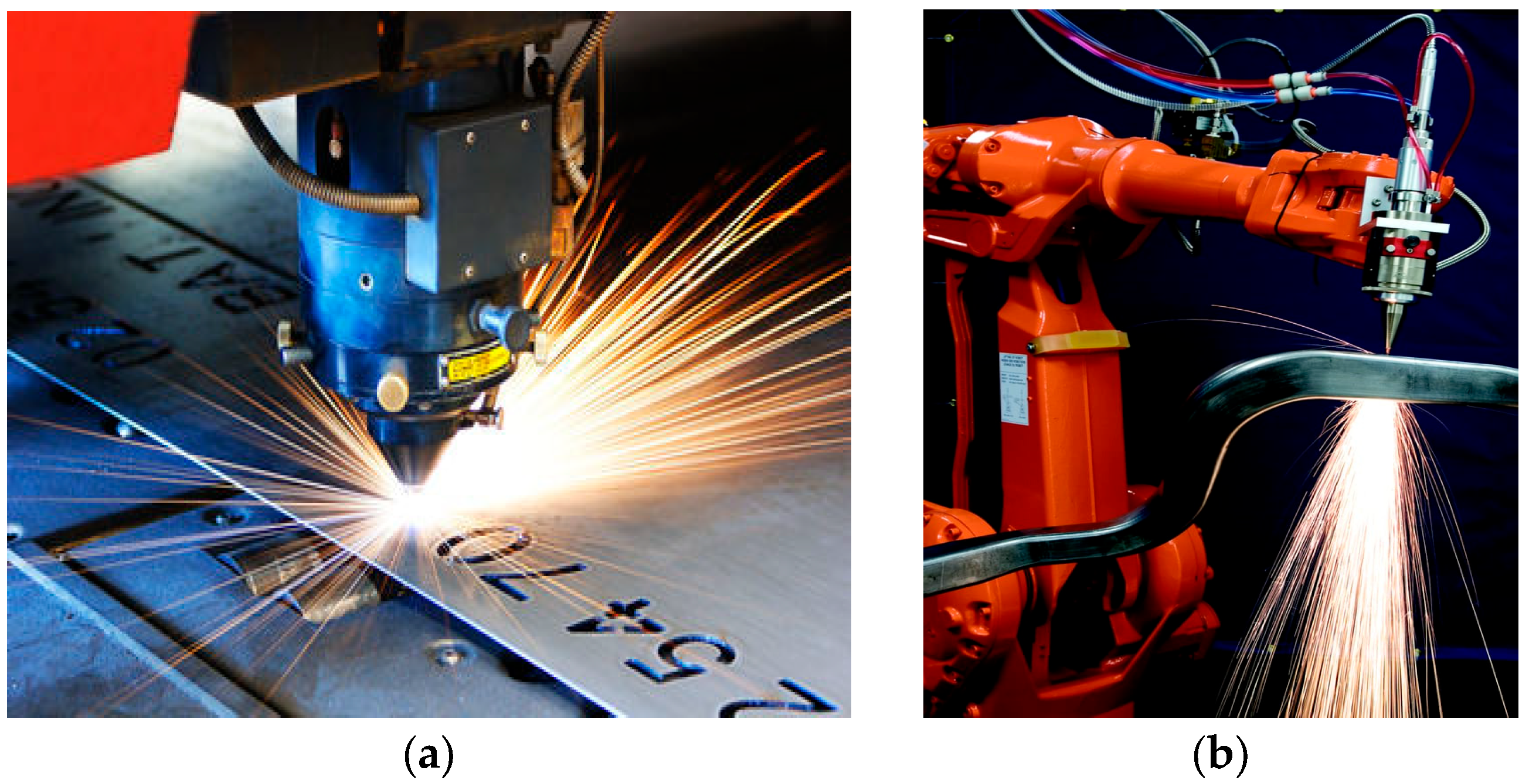
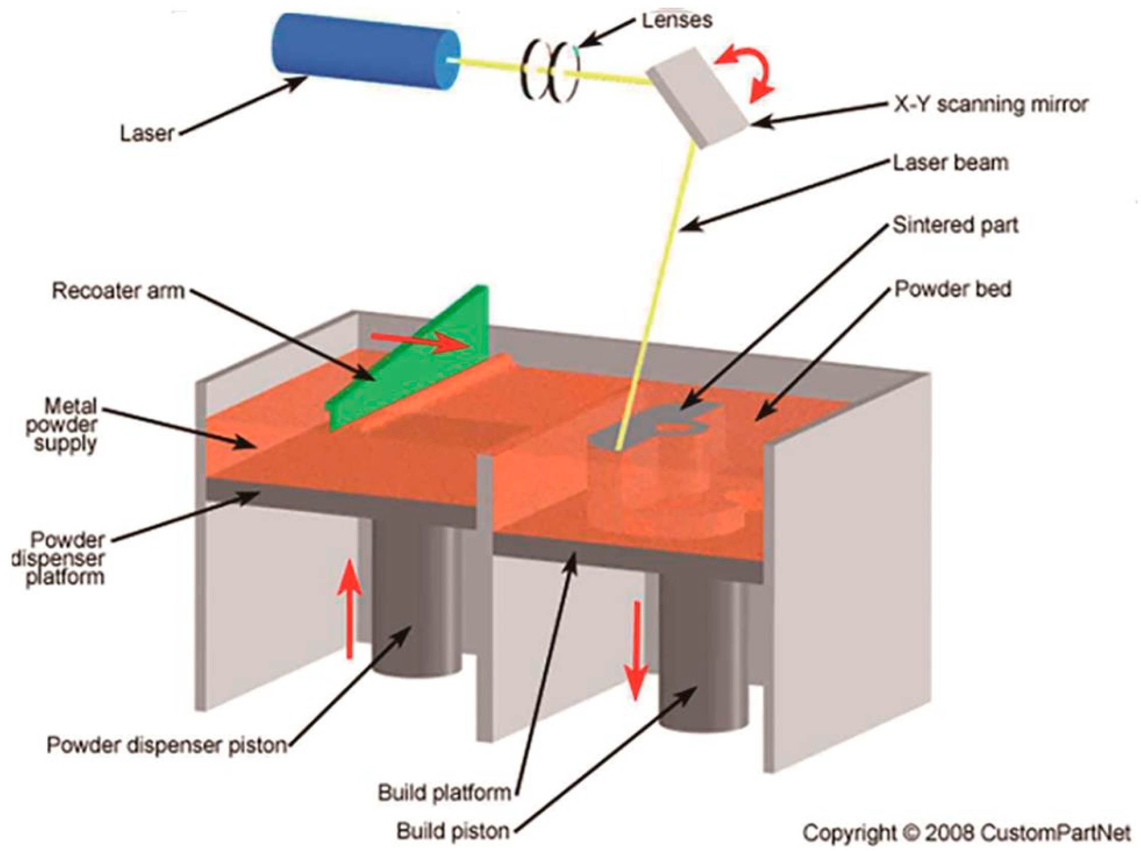
1. Introduction
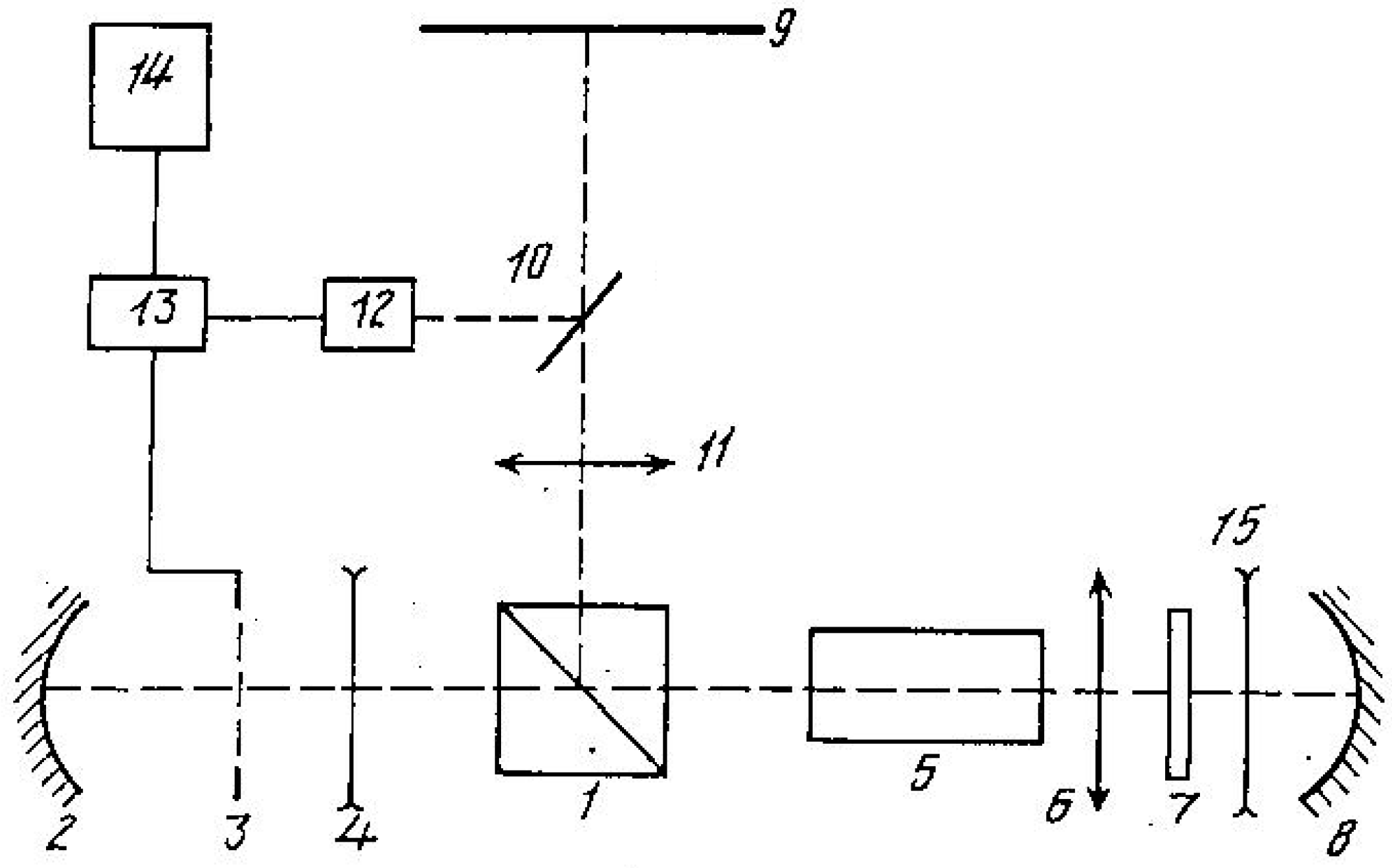
2. LAOSs
- ▪
- Optical Homogeneity: The active medium must be optically uniform to prevent introducing significant distortions into the image.
- ▪
- High Single-Pass Gain: The active medium should exhibit a sufficiently high real single-pass gain to substantially enhance image brightness.
- ▪
- Moderate Gain, Sufficient Power: Rather than being of a high-gain type, the active medium should provide a sufficiently high average power to achieve adequate screen illuminance for viewing.
- ▪
- Spectral Range for Direct Viewing: If the image is to be viewed directly, the active medium should operate within the visible spectrum, either continuously or in pulsed mode.
- ▪
- Adequate Dimensions and Angular Aperture: The size and angular aperture of the active medium must be large enough to accommodate all image-carrying light rays.
- ▪
- High Laser Efficiency and Saturation Operation: The active medium should possess high laser efficiency and operate close to saturation, ensuring optimal overall system performance.
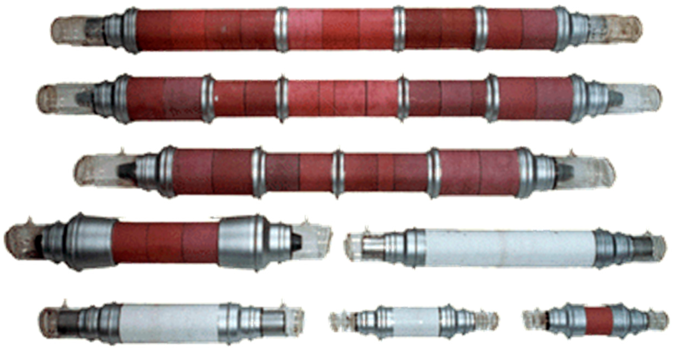
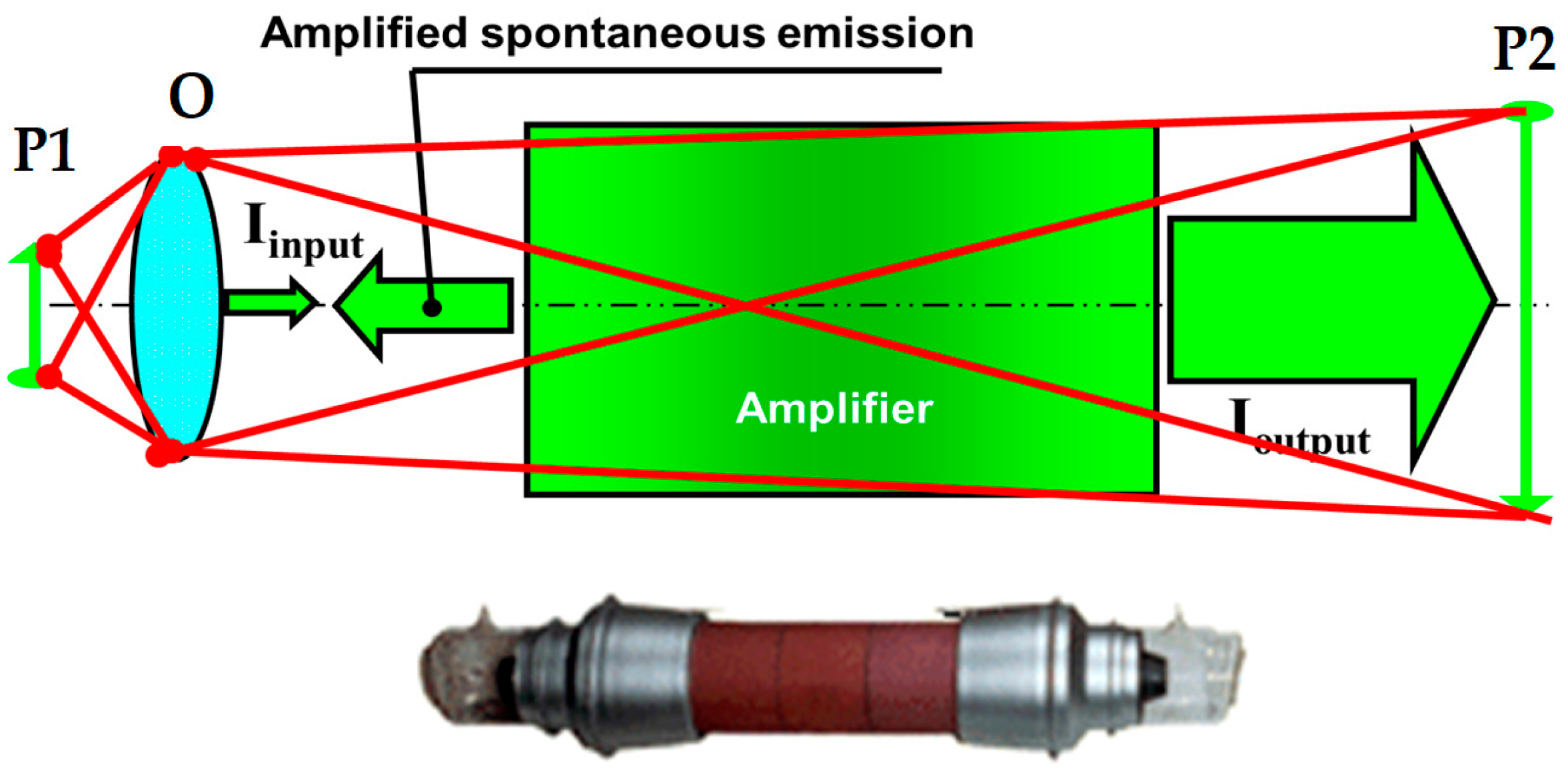
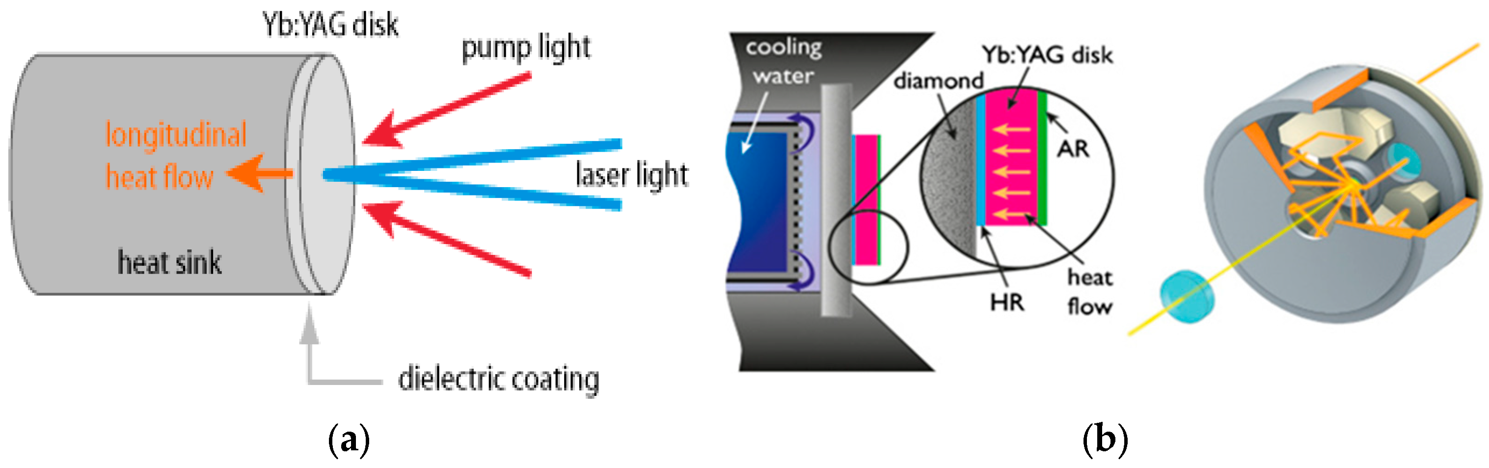
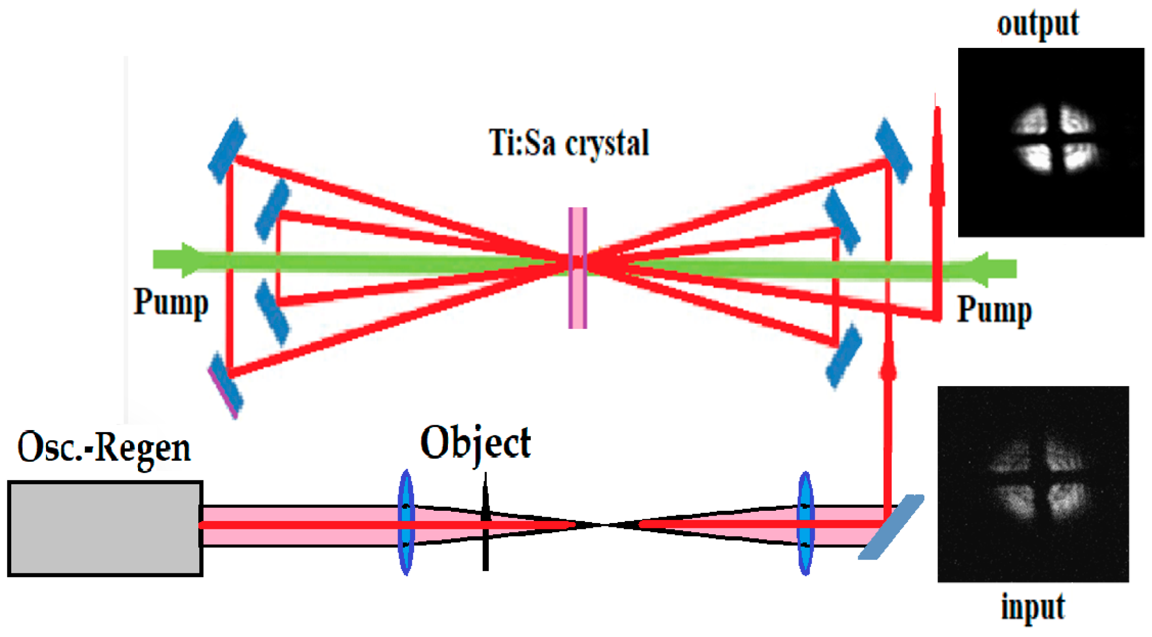
3. LAOSs with Solid-State Disk-Shaped Crystal Amplifiers
4. Conclusions
Funding
Data Availability Statement
Conflicts of Interest
Glossary of Terms
| LAOSs | Laser Active Optical Systems |
| OSs | Optical Systems |
| STLMs | Space-Time Light Modulators |
| DLP | Digital Light Processor |
| DMDs | Digital Micromirror Devices |
| CCD | Charge-Coupled Device |
| ST | Subtractive Technology |
| AT | Additive Technology |
| CW | Continuous Wave regime |
| TD | Thin-Disk crystal |
| MVL | Metal Vapor Laser |
| CVL | Copper Vapor Laser |
| LPM | Laser Projection Microscope |
| ASE | Amplified Spontaneous Emission |
| Ti:Sa | Sapphire doped by Titanium |
| Nd:YAG, Yb:YAG | Yttrium Aluminum Garnet doped by Neodymium or Ytterbium |
| EDP | Extraction During Pumping method of amplification |
| CPA | Chirped Pulse Amplification method |
| kW, TW, PW, | Kilowatt, Terawatt, Petawatt, |
| TPx | Tera Pixel |
References
- Chvykov, V. High-Power Lasers. Encyclopedia 2024, 4, 1236–1249. [Google Scholar] [CrossRef]
- Apollonov, V. High power disk lasers. Nat. Sci. 2013, 5, 556–562. [Google Scholar] [CrossRef]
- Sun, J.; Liu, L.; Han, L.; Zhu, Q.; Shen, X.; Yang, K. 100 kW ultra-high power fiber laser. Opt. Contin. 2022, 1, 1932–1938. [Google Scholar] [CrossRef]
- Zhao, S.; Qi, A.; Wang, M.; Qu, H.; Lin, Y.; Dong, F.; Zheng, W. High-power high-brightness 980 nm lasers with >50% wall-plug efficiency based on asymmetric super large optical cavity. Opt. Express 2018, 26, 3518. [Google Scholar] [CrossRef] [PubMed]
- Zhang, Y.; Killeen, T. Gas Lasers: CO2 lasers—Progressing from a varied past to an application-specific future. Laser Focus World 2016, 4, 3. [Google Scholar]
- Salonitis, K.; Stournaras, A.; Tsoukantas, G.; Stavropoulos, P.; Chryssolouris, G. A theoretical and experimental investigation on limitations of pulsed laser drilling. J. Mater. Process. Technol. 2007, 183, 96–103. [Google Scholar] [CrossRef]
- Naresh; Khatak, P. Laser cutting technique: A literature review. Mater. Today Proc. 2021, 56, 2484–2489. [Google Scholar] [CrossRef]
- Němeček, S.; Mužík, T.; Míšek, M. Differences between Laser and Arc Welding. Phys. Procedia 2012, 39, 67–74. [Google Scholar] [CrossRef]
- Jeyaprakash, N.; Yang, C.-H.; Kumar, D.R. Laser Surface Modification of Materials. In Book Practical Applications of Laser Ablation; Ya, D., Ed.; InTech Open: London, UK, 2020. [Google Scholar] [CrossRef]
- Tepylo, N.; Huang, X.; Patnaik, P.C. Laser-Based Additive Manufacturing Technologies for Aerospace Applications. Adv. Eng. Mater. 2019, 21, 1900617. [Google Scholar] [CrossRef]
- Available online: https://www.ti.com/lit/sl/dlpt019e/dlpt019e.pdf?ts=1736968390037 (accessed on 28 June 2025).
- Fu, N.; Liu, Y.; Ma, X.; Chen, Z. EUV Lithography: State-of-the-Art Review. J. Microelectron. Manuf. 2019, 2, 19020202. [Google Scholar] [CrossRef]
- Refai, H.H.; Sluss, J.J., Jr.; Tull, M.P. Digital micromirror device for optical scanning applications. SPIE Opt. Eng. 2007, 46, 085401. [Google Scholar] [CrossRef]
- Geusic, J.E.; Scovil, H.E.D. A Unidirectional Traveling-Wave Optical Maser. Bell Syst. Tech. J. 1962, 41, 1371. [Google Scholar] [CrossRef]
- Hardy, W.A. Active Image Formation in Lasers. IBM J. Res. Dev. 1965, 9, 31–46. [Google Scholar] [CrossRef]
- Lanczi, E.R. Amplification in a Thick Ruby Lens. Appl. Opt. 1965, 4, 255. [Google Scholar] [CrossRef]
- Zemskov, K.; Isaev, A.; Kazaryan, M.; Petrash, G. Laser projection microscope. Sov. J. Quantum Electron. 1974, 4, 5. [Google Scholar] [CrossRef]
- Zemskov, K.; Isaev, A.; Kazaryan, M.; Petrash, G. Investigations of general characteristics of laser projection microscope. Kvajatovaya Elektron. (Sov. J. Quantum_Electron.) 1976, 3, 35–43. [Google Scholar]
- Isaev, A.; Kazaryan, M.; Petrash, G.G. Efficient pulsed copper vapor laser with high average output power. Pisma v JETP 1972, 16, 40–42. (In Russian) [Google Scholar]
- Burmakin, V.; Evtjunin, A.; Lesnoi, M. Seaied—Off copper vapor laser at atmospheric pressure of buffergas. Quanturn Electron. 1979, 6, 1589–1600. [Google Scholar]
- Hargrove, P.S.; Grove, P.; Kan, T. Copper vapor laser unstable resonator oscilator and oscilator-ainpifier characteristics. IEEE J. Quantum Electron. 1979, 15, 1228–1233. [Google Scholar] [CrossRef]
- Belyaev, V.P.; Zubov, V.V.; Isaev, A.A.; Lyabin Nikolai, A.; Sobolev Yu, F.; Chursin, A.D. Spatial, temporal and power characteristics of copper vapor laser. Quantum Electron. 1985, 12, 74–79. (In Russian) [Google Scholar]
- Zubov, V.V.; Lyabin, N.A.; Mishin, V.I.; Muchnik, M.L.; Parshin, G.D.; Chernyak, E.Y.; Chursin, A.D. Investigation of long life—Time copper vapor laser with improved parameters of pulsed excitatation. Quantum Electron. 1983, 10, 1908–1910. (In Russian) [Google Scholar]
- Liabin, N.I. Resonatorless copper vapor laser with high quality output beam. Quantum Electron. 1989, 16, 637–652. (In Russian) [Google Scholar]
- Naylor, G.; Lewis, P.R.; Kersley, A.J. Performance of high-power copper vapor lasers in an injection-controlled oscillator-amplifier configuration. SPIE Gaslaser Technol. 1988, 894, 110–117. [Google Scholar]
- Zubov, V.V.; Liabin, W.I.; Chursin, D. Efficient system oscillator-amplifier based on copper vapor active elements. Quantum Electron. 1986, 13, 2431–2436. [Google Scholar]
- Zubov, V.V.; Chursin, A.D.; Lesnoy, M.A.; Liabin, N.A.; Ugolnikov, S.A. Copper-vapor lasers with sealed-off active elements. In Proceedings of the SPIE Metal Vapor Lasers and Their Applications, Fryazino, Russia, 1–5 October 1993; Volume 21, pp. 78–89. [Google Scholar]
- Warner, E. Status of copper vapor laser technology at Lawrence Livermore National Laboratory. In Proceedings of the Conference on Lasers and Electro-Optics, Baltimore, MD, USA, 12–17 May 1991. [Google Scholar]
- Petrash, G.G.; Chvykov, V.V.; Zemskov, K.I. Laser amplifiers in Optical Displays and Micromachining Systems. In Proceedings of the SPIE Conference on Microelectronic Structures and MEMS for Optical Processing IV, Santa Clara, CA, USA, 5–10 September 1998; Volume 3513. [Google Scholar]
- Petrash, G. Pulsed gas-discharge lasers. Sov. Phys. Usp. 1972, 14, 747. [Google Scholar] [CrossRef]
- Dumarevskii, Y.D.; Zemskov, K.I.; Kazaryan, M.A.; Petrash, G.G. Projection of images on a large screen with the help of MDS-LC structures and quantum amplifiers. Dokiady Acad. Sci. USSR 1987, 292, 604–607. [Google Scholar]
- Gusev, Y.M.; Dumarevskii, Y.D.; Zemskov, K.I.; Kazaryan, M.A.; Petrash, G.G. Application of MDS-LC structures and brightness amplifiers for projection of TV images on a large screen. Tech. Cine. Telev. 1989, 9, 19–23. [Google Scholar]
- Shimura, T.; Kuroda, K.; Omatsu, T.; Chihara, M.; Ogura, I.; Muro, M. Active projection of LCD-TV with a copper vapor laser brightness amplifier. In Proceedings of the Metal Vapor, Deep Blue, and Ultraviolet Lasers, Los Angeles, CA, USA, 17–20 January 1989; Volume 1041, pp. 67–73. [Google Scholar]
- Zemskov, K.I.; Petrash, G.G.; Chvykov, V.V. Device for Registration, Observation and Processing of Objects. Patent RU2084942 C1, 27 December 1993. [Google Scholar]
- Zemskov, K.I.; Kazaryan, M.A.; Matveey, V.M.; Petrash, G.G.; Samsonova, M.P.; Skripnichenko, A.S. Laser treatment of objects with simultaneous Visual monitoring in the system composed of a copper-vapor oscillator and amplifier. Sov. J. Quantum Electron. 1984, 11, 418–420. [Google Scholar]
- Glikin, L.S.; Gorbarenko, V.A.; Evdokimov, V.A.; Skripnichenko, A.S. Device for Laser Projection Processing of Objects. Patent SU 886387 A1, 14 July 1980. [Google Scholar]
- Glikin, L.S.; Gorbarenko, V.A.; Epihin, V.N.; Skripnichenko, A.S. Device for Laser Projection Processing. Patent SU 1127175 A1, 4 August 1983. [Google Scholar]
- Little, C.E. Applications in Industry. In Pulsed Metal Vapor Lasers; Springer: Cham, The Netherlands, 1996. [Google Scholar]
- Arapova, E.Y.; Isaev, A.A.; Kazaryan, M.A.; Markova, S.V.; Petrash, G.G.; Timofeev, Y.P.; Fridman, S.A. Infrared laser projection microscope. Sov. J. Quant. Electron. 1975, 5, 849. [Google Scholar] [CrossRef]
- Isaev, A.A.; Kazaryan, M.A.; Markova, S.V.; Petrash, G.G. Investigation of pulse infrared stimulated emission from barium vapor. Sov. J. Quantum Electron. 1975, 5, 285. [Google Scholar] [CrossRef]
- Isaev, A.A.; Lemmerman, G.Y.; Markova, S.V.; Petrash, G.G. Characteristics of pulsed lasing due to atomic transitions in barium. Sov. J. Quantum Electron. 1979, 9, 1144. [Google Scholar] [CrossRef]
- Zemskov, K.I.; Kazaryan, M.A.; Petrash, G.G.; Smorchkov, V.N.; Timofeev, Y.P.; Fridman, S.A. Laser projection microscope with barium vapor and luminescent screens for visualization of IR images. Sov. J. Quantum Electron. 1980, 10, 1428. [Google Scholar] [CrossRef]
- Zemskov, K.I.; Isaev, A.A.; Kazaryan, M.A.; Markova, S.V.; Petrash, G.G. Gold Vapor Brightness Amplifier. In Proceedings of the International Conference on Lasers and Their Applications, Dresden, Germany, 28 March–1 April; 1977; p. 362. [Google Scholar]
- Markova, S.V.; Petrash, G.G.; Cherezov, V.M. UV Cold-Vapor Laser. Kvantovaya Electron. 1978, 5, 1583. [Google Scholar]
- Kazaryan, M.A.; Petrash, G.G.; Zemskov, K.I. Gold Vapour Brightness Amplifier. Opt. Commun. 1980, 33, 209–212. [Google Scholar] [CrossRef]
- Isaev, A.A.; Zemskov, K.I.; Kazaryan, M.A.; Kumetsova, T.I.; Petrash, G.G.; Timofeev, Y.P.; Chvykov, V.V. Experimental Investigations of a System in Forming Amplified Images in a Blue Spectral Region by Using Methods of Laser Implification of Image Brightness; Report of the Lebedev Physical Institute; Lebedev Physical Institute: Moscow, Russia, 1992. [Google Scholar]
- Vlasov, D.V.; Ivashkin, P.I.; Isaev, A.A.; Kazaryan, M.A.; Kuznetsova, T.I.; Chvykov, V.V. Amplification of image brightness in strontium vapor. Phys. Scr. 1993, 48, 461. [Google Scholar] [CrossRef]
- Zemskov, K.I.; Kazaryan, M.A.; Mikhkelsoo, V.T.; Petrash, G.G. Excimer XeCl-laser as image brightness amplifier. Kr. Soobshch. Physice FIAN 1987, 10, 49–51. [Google Scholar]
- Osvay, K.; Bor, Z.; Rácz, B.; Heitz, J. Direct Writing and in-situ Material Processing by a Laser-Micromachining Projection Microscope. Appl. Phys. A 1994, 58, 211–214. [Google Scholar] [CrossRef]
- Little, C.E. Applications in Science and Technology. In Pulsed Metal Vapor Lasers; Springer: Dordrecht, The Netherlands, 1996. [Google Scholar]
- Vasil’ev, Y.P.; Dumarevsky, Y.D.; Zemskov, K.I.; Kazaryan, M.A.; Medvedeva, L.V.; Petrovicheva, G.A.; Chvykov, V.V. A Phase Object in the Projection System with Brightness Amplification. Phys. Scr. 1995, 51, 92–93. [Google Scholar] [CrossRef]
- Dougherty, T. Photodynamic therapy: Status and potential. Oncology 1989, 3, 67–73. [Google Scholar]
- Zemskov, K.I.; Ivanov, A.V.; Kazaryan, M.; Faenov, A.; Chvykov, V.V.; Kim, J.J.; Kimball, R.; Wisoff, P.J. Application of metal vapor lasers for selective effect to pathological tissues. In SPIE Proceedings of the Metal Vapor Laser Technology and Applications, Los Angeles, CA, USA, 17–20 January 1989; Volume 1041. pp. 86–90. [Google Scholar]
- Ivanov, A.; Petrash, G.; Kazarian, M.; Zemskov, K.; Faenov, A.; Chvykov, V. Selectivity of the laser radiation effect on biological tissues. Doclady Akad. Nauk. SSSR 1989, 305, 736–740. [Google Scholar]
- Vasiliev, Y.P.; Zemskov, K.I.; Ivanov, A.V.; Kazaryan, M.A.; Petrash, G.G.; Chvykov, V.V. Active optical systems: Medical and biological applications. Proc. Lebedev Phys. Inst. 1991, 206, 136–148. [Google Scholar]
- Little, C.E. Metal Vapour Laser Systems in Biology and Medicine. In Pulsed Metal Vapor Lasers; Springer: Dordrecht, The Netherlands, 1996. [Google Scholar]
- Asinovskii, E.I.; Batenin, V.M.; Klimovskii, I.I.; Markovets, V.V. Observation of a melting traces formation of carbon on the pyrographic cathode surface during the burning of the atmospheric carbon arc. Dokl. Akad. Nauk. 1999, 369, 1–6. [Google Scholar]
- Buzhinsky, R.O.; Savransky, V.V.; Zemskov, K.I.; Isaev, A.A.; Buzhinsky, O.I. Observation of objects under intense plasma background illumination. Plasma Phys. Rep. 2010, 36, 1269–1271. [Google Scholar] [CrossRef]
- Evtushenko, G.S.; Trigub, M.V.; Gubarev, F.A.; Evtushenko, T.G.; Torgaev, S.N.; Shiyanov, D.V. Laser monitor for non-destructive testing of materials and processes shielded by intensive background lighting. Rev. Sci. Instrum. 2014, 85, 033111. [Google Scholar] [CrossRef]
- Li, L.; Antipov, P.A.; Mostovshchikov, A.V.; Ilyin, A.P. Fedor Alexandrovich Gubarev, Laser Systems for Distant Monitoring of Nanopowder Combustion. Prog. Electromagn. Res. M 2019, 84, 85–93. [Google Scholar] [CrossRef]
- Li, L.; Mostovshchikov, A.V.; Ilyin, A.P.; Smirnov, A.; Gubarev, F.A. Optical system with brightness amplification for monitoring the combustion of aluminum-based nanopowders. IEEE Trans. Instrum. Meas. 2020, 69, 457–468. [Google Scholar] [CrossRef]
- Li, L.; Mostovshchikov, A.V.; Ilyin, A.P.; Antipov, P.A.; Shiyanov, D.V.; Gubarev, F.A. Imaging system with brightness amplification for a metal-nanopowder-combustion study. J. Appl. Phys. 2020, 127, 194503. [Google Scholar] [CrossRef]
- Triguba, M.V.; Vasneva, N.A.; Kitlerb, V.D.; Evtushenkoa, G.S. The Use of a Bistatic Laser Monitor for High-Speed Imaging of Combustion Processes. Atmos. Ocean. Opt. 2021, 34, 154. [Google Scholar] [CrossRef]
- Trigub, M.V.; Vasnev, N.A.; Evtushenko, G.S. Bistatic laser monitor for imaging objects and processes. Appl. Phys. B 2020, 126, 2–7. [Google Scholar] [CrossRef]
- MTrigub, V.; Vasnev, N.A.; Evtushenko, G.S. Operating features of a copper bromide brightness amplifier in the monostatic laser monitor. Opt. Commun. 2021, 480, 126486. [Google Scholar]
- Gubarev, F.A.; Mostovshchikov, A.V.; Ilyin, A.P.; Li, L.; Fedorov, A.I.; Burkin, E.Y.; Sviridov, V.V. A two-channel laser monitor for observing processes of high-temperature combustion of metal nanopowders. Tech. Phys. Lett. 2021, 47, 344–347. [Google Scholar] [CrossRef]
- Li, L.; Shiyanov, D.V.; Gubarev, F.A. Spatial–temporal radiation distribution in a CuBr vapor brightness amplifier in a real laser monitor scheme. Appl. Phys. B 2020, 126, 155. Available online: https://link.springer.com/article/10.1007/s00340-020-07511-7 (accessed on 28 June 2025). [CrossRef]
- Asratyan, A.A.; Bulychev, N.A.; Feofanov, I.N.; Kazaryan, M.A.; Krasovskii, V.I.; Lyabin, N.A.; Pogosyan, L.A.; Sachkov, V.I.; Zakharyan, R.A. Laser processing with specially designed laser beam. Appl. Phys. A 2016, 122, 434. [Google Scholar] [CrossRef]
- Trigub, M.V.; Evtushenko, G.S.; Torgaev, S.N.; Shiyanov, D.V.; Evtushenko, T.G. Copper bromide vapor brightness amplifiers with 100 kHz pulse repetition frequency. Opt. Commun 2016, 376, 81–85. [Google Scholar] [CrossRef]
- Trigub, M.V.; Vasnev, N.A. Laser active optical systems based on copper bromide active medium for high contrast and power images active formation. Opt. Laser Technol. 2023, 161, 109147. [Google Scholar] [CrossRef]
- Vasnev, N.A.; Trigub, M.V. Investigation of ASE contribution to copper bromide amplifier output signal. Opt. Quant. Electron. 2024, 56, 158. [Google Scholar] [CrossRef]
- Trigub, M.V.; Kulagin, A.E. Semi-empirical model of a copper bromide vapor brightness amplifier. Opt. Commun. 2024, 573, 1–6. [Google Scholar] [CrossRef]
- Chvykov, V. Laser Active Optical Systems (LAOS) for industrial applications. In Proceedings of the CLEO ATu3C CLEO, San Jose, CA, USA, 14–19 May 2017. [Google Scholar]
- Speiser, J. Scaling of thin-disk lasers—Influence of amplified spontaneous emission. J. Opt. Soc. Am. B 2009, 26, 26–35. [Google Scholar] [CrossRef]
- Giesen, A.; Speiser, J. Fifteen years of work on thin-disk lasers: Results and scaling laws. IEEE J. Sel. Top. Quantum Electron. 2007, 13, 598. [Google Scholar] [CrossRef]
- Schad, S.-S.; Stolzenburg, C.; Michel, K.; Sutter, D. Latest Advances in High Brightness Disk Lasers: High power performance from CW to short and ultra short pulses. Laser Tech. J. 2014, 11, 49–53. [Google Scholar] [CrossRef]
- Saraceno, C.J.; Sutter, D.; Metzger, T.; Ahmed, M.A. The amazing progress of high-power ultrafast thin-disk lasers. J. Eur. Opt. Soc.-Rapid Publ. 2019, 15, 15. [Google Scholar] [CrossRef]
- Papastathopoulos, E.; Baumann, F.; Bocksrocker, O.; Gottwald, T.; Killi, A.; Metzger, B.; Schad, S.S.; Speker, N.; Ryba, T.; Zaske, S. High-power high-brightness disk lasers for advanced applications. In Proceedings of the Solid State Lasers XXX: Technology and Devices, Online, 6–12 March 2021; Volume 11664, p. 116640M. [Google Scholar] [CrossRef]
- Available online: https://www.trumpf.com/en_US/products/lasers/disk-lasers/trudisk (accessed on 28 June 2025).
- Nubbemeyer, T.; Kaumanns, M.; Ueffing, M.; Gorjan, M.; Alismail, A.; Fattahi, H.; Brons, J.; Pronin, O.; Barros, H.G.; Major, Z.; et al. 1 kW, 200 mJ picosecond thin-disk laser system. Opt. Lett. 2017, 42, 1381–1384. [Google Scholar] [CrossRef] [PubMed]
- Photonics Encyclopedia. Available online: https://www.rp-photonics.com/thin_disk_lasers.html (accessed on 6 May 2024).
- Chvykov, V.; Nagymihaly, R.; Cao, H.; Kalashnikov, M.; Osvay, K. Design of a Thin Disk Amplifier with Extraction During Pumping for high peak and average power Ti:Sa systems (EDP-TD). Opt. Express 2016, 24, 3721. [Google Scholar] [CrossRef]
- Chvykov, V.; Yanovsky, V.; Bahk, S.-W.; Kalintchenko, G.; Mourou, G. Suppression of parasitic lasing in multi-pass Ti-sapphire amplifiers. In Proceedings of the CLEO OSA Technical Digest, CLEO 2003, CWA34, Baltimore, MD, USA, 6 June 2003. [Google Scholar]
- Chvykov, V.; Krushelnick, K. Large aperture multi-pass amplifiers for high peak power lasers. Opt. Commun. 2012, 285, 2134–2136. [Google Scholar] [CrossRef]
- Chvykov, V.; Nees, J.; Krushelnick, K. Transverse amplified spontaneous emission: The limiting factor for output energy of ultra-high-power lasers. Opt. Commun. 2014, 312, 216–221. [Google Scholar] [CrossRef]
- Chvykov, V.; Cao, H.; Nagymihaly, R.; Kalashnikov, M.P.; Khodakovskiy, N.; Glassock, R.; Ehrentraut, L.; Schnuerer, M.; Osvay, K. High peak and average power Ti:sapphire thin disk amplifier with extraction during pumping. Opt. Lett. 2016, 41, 3017. [Google Scholar] [CrossRef]
- Kabacinski, A.; Jeandet, A.; Pellegrina, A.; Larmonier, P.; Lavenu, L.; Chalus, O.; Ricaud, S.; Simon-Boisson, C.; Besaucèle, H. High average power room temperature laser based on 300 mJ 100 Hz Ti:Sa disk amplifier. Opt. Lett. 2025. in print. [Google Scholar]
- Nagymihaly, R.S.; Cao, H.; Papp, D.; Hajas, G.; Kalashnikov, M.; Osvay, K.; Chvykov, V. Liquid-cooled Ti:Sapphire thin disk amplifiers for high average power 100-TW systems. Opt. Express 2017, 25, 6664. [Google Scholar] [CrossRef]
- Cao, H.; Nagymihaly, R.S.; Chvykov, V. Cross thin slab kW-class Ti: Sapphire amplifiers. Laser Phys. 2019, 29, 065802. [Google Scholar] [CrossRef]
- Chvykov, V.; Chi, H.; Wang, Y.; Dehne, K.; Berrill, M.; Rocca, J.J. Demonstration of a side-pumped cross-seeded thin-slab pre-amplifier for high-power Ti:Sa laser systems. Opt. Lett. 2022, 47, 3463. [Google Scholar] [CrossRef]
- Chvykov, V. Ti: Sa Crystals in Ultra-High Peak and Average Power Laser Systems. Crystals 2021, 11, 841. [Google Scholar] [CrossRef]
- Chvykov, V. Ti:Sa Crystal Geometry Variation vs. Final Amplifiers of CPA Laser Systems Parameters. Crystals 2022, 12, 1127. [Google Scholar] [CrossRef]
- Damm, T.; Kaschke, M.; Noack, F.; Wilhelmi, B. Compression of picosecond pulses from a solid-state laser using self-phase modulation in graded-index fibers. Opt. Lett. 1985, 10, 176. [Google Scholar] [CrossRef] [PubMed]
- Strickland, D.; Mourou, G. Compression of amplified chirped optical pulses. Opt. Commun. 1985, 56, 219. [Google Scholar] [CrossRef]
- Yoon, J.W.; Kim, Y.G.; Choi, I.W.; Sung, J.H.; Lee, H.W.; Lee, S.K.; Nam, C.H. Realization of laser intensity over 1023 W/cm2. Optica 2021, 8, 630–635. [Google Scholar] [CrossRef]
- Radier, C.; Chalus, O.; Charbonneau, M.; Thambirajah, S.; Deschamps, G.; David, S.; Barbe, J.; Etter, E.; Matras, G.; Ricaud, S.; et al. 10 PW peak power femtosecond laser pulses at ELI-NP. High Power Laser Sci. Eng. 2022, 10, e21. [Google Scholar] [CrossRef]


| Devices | Total Average Output power, W | Beam Diameter, mm | Repet. Rate, kHz | Consumed Power kW | |
|---|---|---|---|---|---|
| 1. Active elements | Rectifier | Wall plug | |||
| Kulon-Sil | 1–1.5 | 7 | 8–30 | 0.5 | 0.6 |
| GL-204M | 4–6 | 12 | 8–30 | 1.0 | 1.2 |
| GL-202M | 5–8 | 12 | 8–30 | 1.8 | 2.2 |
| Kulon-S | 8–12 | 12 | 8–30 | 1.4 | 1.7 |
| UL-102M * | 8–12 | 20 | 5–20 | 1.8 | 2.2 |
| GL-201M | 25–35 | 20 | 5–20 | 3.0 | 3.6 |
| GL-201D | 35–45 | 20 | 5–20 | 4.0 | 4.8 |
| Crystal-32D | 45–55 | 32 | 5–15 | 5.0 | 6.0 |
| 2. Laser | |||||
| Columbia-L | 3–5 | 12 | 8–18 | 1.3 | 1.5 |
| LGI-101M | 5–8 | 12 | 8–12 | 2.5 | 2.8 |
| LGI-202M | 25–30 | 20 | 8–12 | 4.0 | 4.5 |
| Active Media | Wavelength, nm | Rep. Rate kHz | N, *105 | Small Signal Gain | Pam/Pl a ** | Measured eff. Amplification *** |
|---|---|---|---|---|---|---|
| Cu | 510.5 | 10 | 12 | 0.2 | 0.44 | 1.6 × 10⁴ |
| CuCl | 510.5 | 10 | 32 | 0.56 | ||
| CuBr | 510.5 | 14 | 32 | 0.59 | 6.5 × 10³ | |
| Au | 627.8 | 10 | 5.4 | 0.11 | 0.34 | 104 |
| Mn | green | 7 | 5.7 | 0.11 | 0.18 | 103 |
| Mn | IR | 7 | 1.1 | 0.13 | 0.2 | 3.5 × 10³ |
| Pb | 722.9 | 12 | 3.1 | 0.12 | 0.52 | 3 × 10³ |
| Ba | 1500 | 8 | 2.1 | 0.17 | 0.82 | 2.7 × 10³ |
Disclaimer/Publisher’s Note: The statements, opinions and data contained in all publications are solely those of the individual author(s) and contributor(s) and not of MDPI and/or the editor(s). MDPI and/or the editor(s) disclaim responsibility for any injury to people or property resulting from any ideas, methods, instructions or products referred to in the content. |
© 2025 by the author. Licensee MDPI, Basel, Switzerland. This article is an open access article distributed under the terms and conditions of the Creative Commons Attribution (CC BY) license (https://creativecommons.org/licenses/by/4.0/).
Share and Cite
Chvykov, V. Laser Active Optical Systems (LAOSs) for Material Processing. Micromachines 2025, 16, 792. https://doi.org/10.3390/mi16070792
Chvykov V. Laser Active Optical Systems (LAOSs) for Material Processing. Micromachines. 2025; 16(7):792. https://doi.org/10.3390/mi16070792
Chicago/Turabian StyleChvykov, Vladimir. 2025. "Laser Active Optical Systems (LAOSs) for Material Processing" Micromachines 16, no. 7: 792. https://doi.org/10.3390/mi16070792
APA StyleChvykov, V. (2025). Laser Active Optical Systems (LAOSs) for Material Processing. Micromachines, 16(7), 792. https://doi.org/10.3390/mi16070792