
Influence of Nonlinear Effects Induced by Mode Coupling on Vibration Trajectories of MEMS Micromirrors


Abstract
1. Introduction
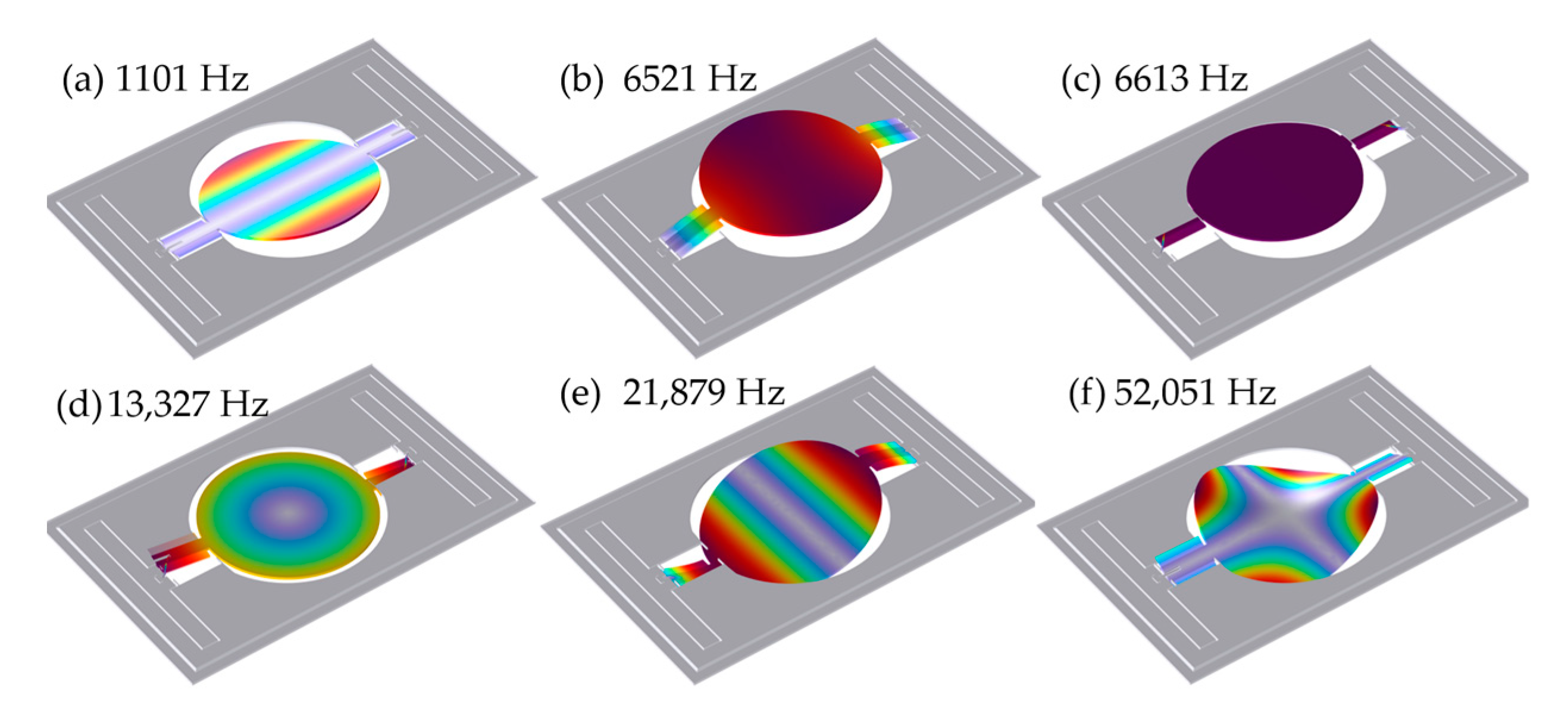
2. Micromirror Mode Analysis
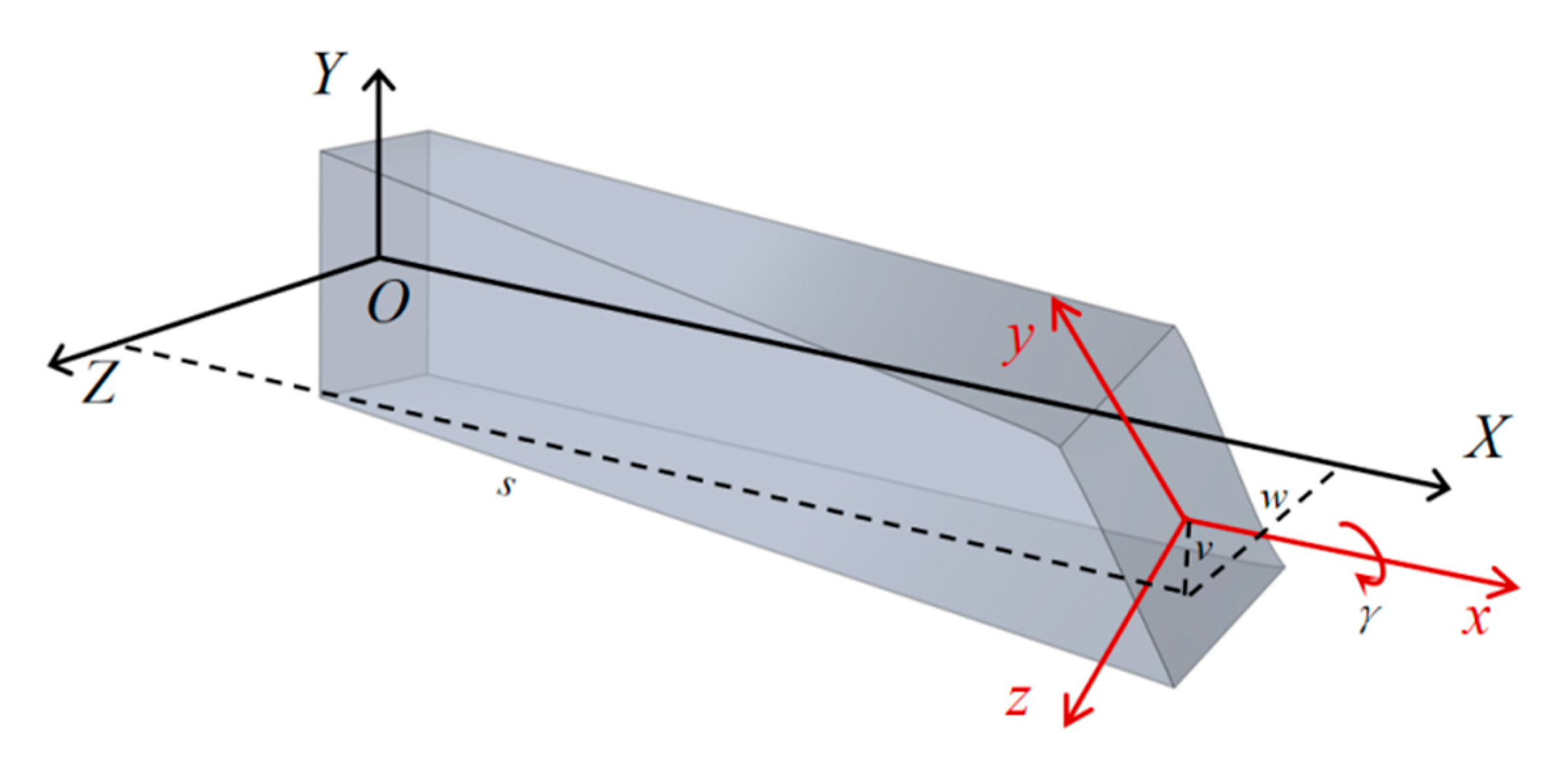
3. Vibration Trajectory Model Construction
4. Simulation and Experiment Results
4.1. Simulation
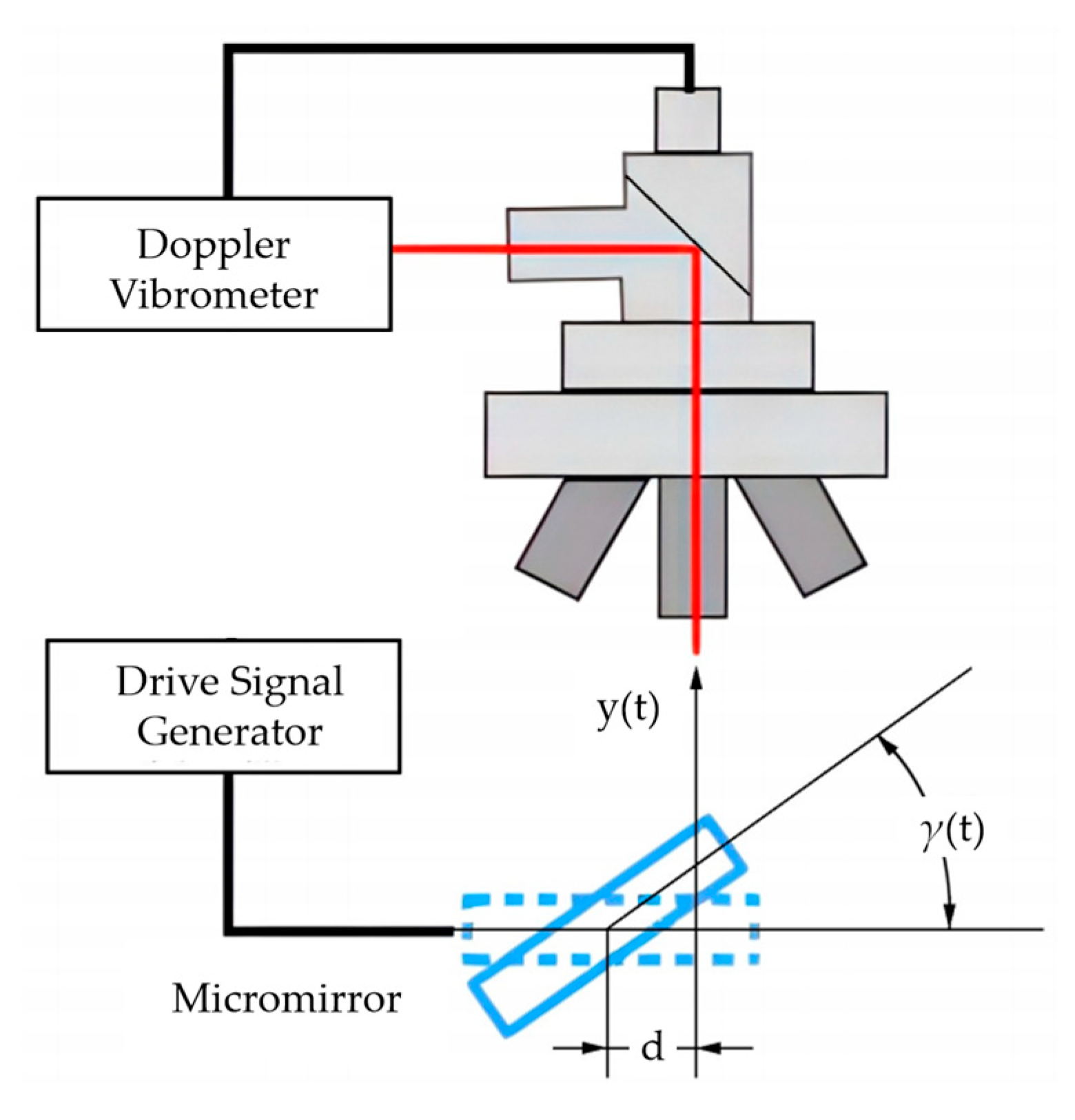
4.2. Experiment
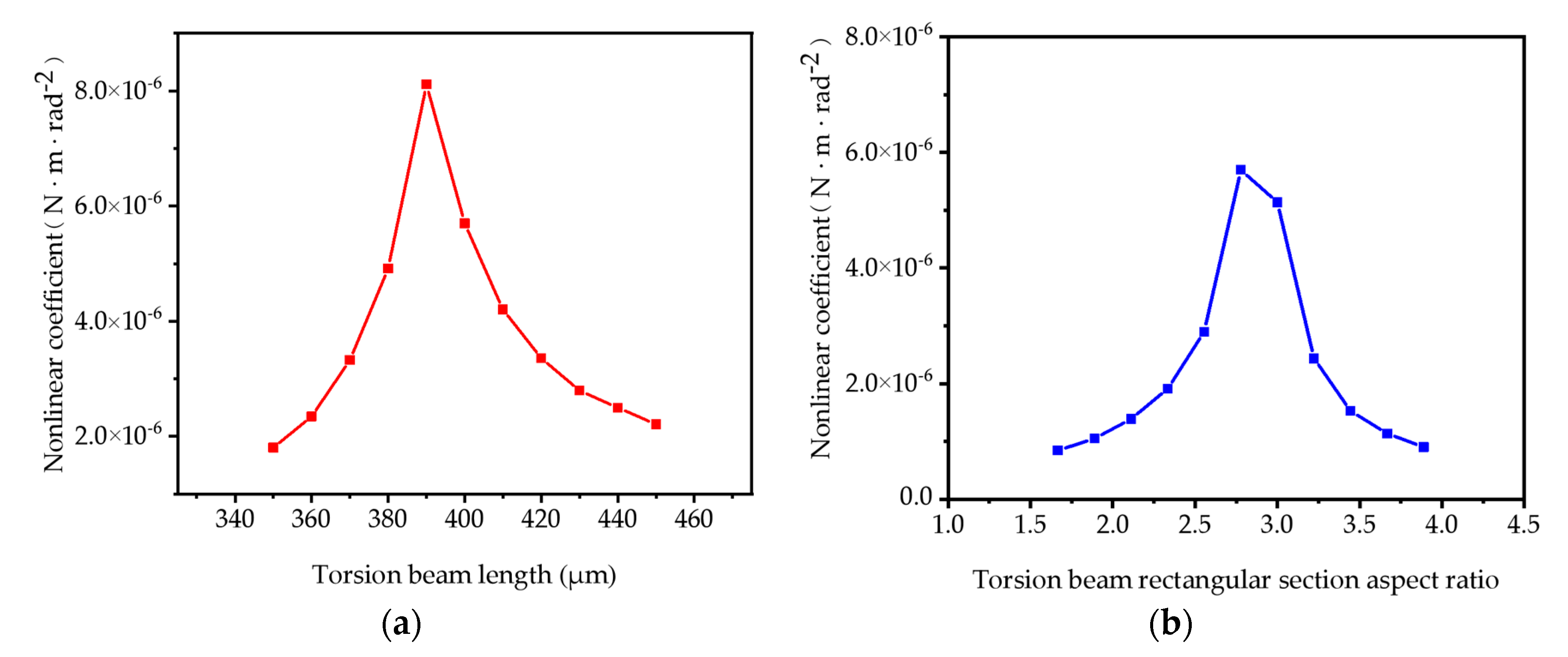
5. Mode Coupling Nonlinearity Effect Mitigation via Structural Parameter Optimization
6. Conclusions
Author Contributions
Funding
Data Availability Statement
Conflicts of Interest
References
- Ju, S.; Jeong, H.; Park, J.H.; Bu, J.U.; Ji, C.H. Electromagnetic 2D scanning micromirror for high definition laser projection displays. IEEE Photonics Technol. Lett. 2018, 30, 2072–2075. [Google Scholar] [CrossRef]
- Takashima, Y.; Hellman, B. imaging lidar by digital micromirror device. Opt. Rev. 2020, 27, 400–408. [Google Scholar] [CrossRef]
- Wang, D.; Watkins, C.; Xie, H. MEMS mirrors for LiDAR: A review. Micromachines 2020, 11, 456. [Google Scholar] [CrossRef]
- Yang, T.; Zhang, G.; Li, H.; Zhou, X. Hybrid 3d shape measurement using the mems scanning micromirror. Micromachines 2019, 10, 47. [Google Scholar] [CrossRef] [PubMed]
- Xu, F.; Qiao, D.; Xia, C.; Song, X.; Zheng, W.; He, Y.; Fan, Q. A semi-coaxial MEMS LiDAR design with independently adjustable detection range and angular resolution. Sens. Actuators A Phys. 2021, 326, 112715. [Google Scholar] [CrossRef]
- Yang, D.; Qiao, D.; Xia, C. Curved light surface model for calibration of a structured light 3D modeling system based on striped patterns. Opt. Express 2020, 28, 33240–33253. [Google Scholar] [CrossRef]
- Tortschanoff, A.; Lenzhofer, M.; Frank, A.; Wildenhain, M.; Sandner, T.; Schenk, H.; Scherf, W.; Kenda, A. Position encoding and phase control of resonant MOEMS mirrors. Sens. Actuators A Phys. 2010, 162, 235–240. [Google Scholar] [CrossRef]
- Danylenko, V.A.; Mykulyak, S.V.; Skurativskyi, S.I. Energy redistribution in hierarchical systems of oscillators. Eur. Phys. J. B 2015, 88, 1–8. [Google Scholar] [CrossRef]
- Comi, C.; Corigliano, A.; Frangi, A.; Zega, V. Linear and Nonlinear Mechanics in MEMS. In Silicon Sensors and Actuators: The Feynman Roadmap; Vigna, B., Ferrari, P., Villa, F.F., Lasalandra, E., Zerbini, S., Eds.; Springer International Publishing: Cham, Switzerland, 2022; pp. 389–437. [Google Scholar]
- Yoo, H.W.; Albert, S.; Schitter, G. Accurate analytic model of a parametrically driven resonant MEMS mirror with a Fourier series-based torque approximation. J. Microelectromech. Syst. 2020, 29, 1431–1442. [Google Scholar] [CrossRef]
- Asadi, K.; Yu, J.; Cho, H. Nonlinear couplings and energy transfers in micro-and nano-mechanical resonators: Intermodal coupling, internal resonance and synchronization. Philos. Trans. R. Soc. A 2018, 376, 20170141. [Google Scholar] [CrossRef]
- Wei, S.; Song, J.; Wang, J.; You, Z. Enhancing MEMS scanning mirror projection displays through phase-shifted Lissajous trajectory optimization. Sens. Actuators A Phys. 2025, 387, 116447. [Google Scholar] [CrossRef]
- Wang, J.; Zhang, G.; You, Z. UKF-based MEMS micromirror angle estimation for LiDAR. J. Micromech. Microeng. 2019, 29, 035005. [Google Scholar] [CrossRef]
- Liu, T.; Pan, T.; Wang, P.; Qin, S.; Xie, H. Scanning optimization of an electrothermally-actuated MEMS mirror for applications in optical coherence tomography endoscopy. Sens. Actuators A Phys. 2022, 335, 113377. [Google Scholar] [CrossRef]
- Dean, R.N.; Anderson, A.; Reeves, S.J.; Flowers, G.T.; Hodel, A.S. Electrical noise in MEMS capacitive elements resulting from environmental mechanical vibrations in harsh environments. IEEE Trans. Ind. Electron. 2010, 58, 2697–2705. [Google Scholar] [CrossRef]
- Nabholz, U.; Heinzelmann, W.; Mehner, J.E.; Degenfeld-Schonburg, P. Amplitude-and gas pressure-dependent nonlinear damping of high-Q oscillatory MEMS micro mirrors. J. Microelectromech. Syst. 2018, 27, 383–391. [Google Scholar] [CrossRef]
- Zhou, Z.; Hu, K.; Tu, E.; Meng, G.; Zhang, W. Cross-Axis Bending-Torsion Coupled Dynamic Model for Thermal-Induced Frequency Drift of 2D MEMS Micromirrors. J. Sound. Vib. 2025, 613, 119190. [Google Scholar] [CrossRef]
- Ahmad, M.; Bahri, M.; Sawan, M. MEMS Micromirror Actuation Techniques: A Comprehensive Review of Trends, Innovations, and Future Prospects. Micromachines 2024, 15, 1233. [Google Scholar] [CrossRef]
- Brunner, D.; Yoo, H.W.; Thurner, T.; Schitter, G. Data based modelling and identification of nonlinear SDOF MOEMS mirror. In Proceedings of the MOEMS and Miniaturized Systems XVIII, San Francisco, CA, USA, 4 March 2019. [Google Scholar]
- Lu, K.; Wu, K.; Li, Q.; Zhou, X.; Zhang, Y.; Xi, X.; Wu, X.; Xiao, D. Dispersive resonance modulation based on the mode-coupling effect in a capacitive micromechanical resonator. Phys. Rev. Appl. 2022, 18, 034006. [Google Scholar] [CrossRef]
- Zamanzadeh, M.; Ouakad, H.M.; Azizi, S. Theoretical and experimental investigations of the primary and parametric resonances in repulsive force based MEMS actuators. Sens. Actuators A Phys. 2020, 303, 111635. [Google Scholar] [CrossRef]
- Frangi, A.; Guerrieri, A.; Boni, N.; Carminati, R.; Soldo, M.; Mendicino, G. Mode coupling and parametric resonance in electrostatically actuated micromirrors. IEEE Trans. Ind. Electron. 2017, 65, 5962–5969. [Google Scholar] [CrossRef]
- Shi, Z.; Pu, D.; Huan, R.; Wang, X.; Jiang, Z.; Wei, X. Mode interaction induced response flattening in two mechanically coupled micro-resonators. Mech. Syst. Sig. Process. 2022, 177, 109164. [Google Scholar] [CrossRef]
- Opreni, A.; Furlan, M.; Bursuc, A.; Boni, N.; Mendicino, G.; Carminati, R.; Frangi, A. One-to-one internal resonance in a symmetric MEMS micromirror. Appl. Phys. Lett. 2022, 121, 173501. [Google Scholar] [CrossRef]
- Kumar, P.; Inamdar, M.M.; Pawaskar, D.N. Investigation of 3:1 Internal Resonance of Electrostatically Actuated Microbeams With Flexible Supports. In Proceedings of the ASME 2020 International Design Engineering Technical Conferences and Computers and Information in Engineering Conference, Virtual, 17–19 August 2020. [Google Scholar]
- Yu, J.; Donmez, A.; Herath, H.; Cho, H. One-to-two internal resonance in a micro-mechanical resonator with strong Duffing nonlinearity. J. Micromech. Microeng. 2023, 34, 015007. [Google Scholar] [CrossRef]
- Ruzziconi, L.; Jaber, N.; Kosuru, L.; Bellaredj, M.L.; Younis, M.I. Two-to-one internal resonance in the higher-order modes of a MEMS beam: Experimental investigation and theoretical analysis via local stability theory. Int. J. Non Linear Mech. 2021, 129, 103664. [Google Scholar] [CrossRef]
- Kumar, P.; Pawaskar, D.N.; Inamdar, M.M. Investigating internal resonances and 3: 1 modal interaction in an electrostatically actuated clamped-hinged microbeam. Meccanica 2022, 57, 143–163. [Google Scholar] [CrossRef]
- Czaplewski, D.A.; Strachan, S.; Shoshani, O.; Shaw, S.W.; López, D. Bifurcation diagram and dynamic response of a MEMS resonator with a 1: 3 internal resonance. Appl. Phys. Lett. 2019, 114, 254104. [Google Scholar] [CrossRef]
- Kundu, S.K.; Ogawa, S.; Kumagai, S.; Fujishima, M.; Hane, K.; Sasaki, M. Nonlinear spring effect of tense thin-film torsion bar combined with electrostatic driving. Sens. Actuators A Phys. 2013, 195, 83–89. [Google Scholar] [CrossRef]
- Rahmanian, S.; Awrejcewicz, J. Flexural–torsional modal interaction in MEMS actuators initiated by minuscule asymmetry. Nonlinear Dyn. 2024, 1–41. [Google Scholar] [CrossRef]
- Sun, W.; Chen, H.; Yeow, J.T. Barrier Lyapunov function-based output regulation control of an electromagnetic micromirror with transient performance constraint. IEEE Trans. Syst. Man Cybern. 2021, 52, 4080–4091. [Google Scholar] [CrossRef]
- Zhang, R.; Qu, J.; Cao, Y.; Zhang, X.; Jia, Y.; Wang, X.; Zhou, W.; Xie, H. An integrated capacitive sensing method for electrostatic comb-drive micromirrors. Sens. Actuators A Phys. 2023, 357, 114416. [Google Scholar] [CrossRef]
- Pham, D.D.; Singh, R.P.; Yan, D.L.; Tiew, K.T.; Bernal, O.D.; Langer, T.; Hirshberg, A.; Je, M. Position sensing and electrostatic actuation circuits for 2-D scanning MEMS micromirror. In Proceedings of the 2011 Defense Science Research Conference and Expo (DSR), Singapore, 3–5 August 2011. [Google Scholar]
- Carvalho, E.C.; Gonçalves, P.B.; Rega, G. Multiple internal resonances and nonplanar dynamics of a cruciform beam with low torsional stiffness. Int. J. Solids Struct. 2017, 121, 117–134. [Google Scholar] [CrossRef]
- Xia, C.; Qiao, D.; Peng, A.; Chen, Z.; Song, X.; Song, X.; Xiong, P. Analytical Solution of Nonlinear Dynamics in Electrostatically Driven MEMS Scanning Mirrors. J. Microelectromech. Syst. 2024, 33, 697–710. [Google Scholar] [CrossRef]


| Parameter | Value | Unit |
|---|---|---|
| Mirror plate radius, R | 1.5 | mm |
| Torsion beam width, b | 18 | μm |
| Torsion beam length, l | 400 | μm |
| Movable comb beam width, B | 265 | μm |
| Movable comb beam length, L | 0.9 | mm |
| Device thickness, h | 50 | μm |
| Parameter | Value | Unit |
|---|---|---|
| Inertia, J | 4.64 × 10⁻¹³ | Kg·m2 |
| Torsional stiffness, k | 2.35 × 10⁻⁵ | N·m·rad−1 |
| Damping coefficient, c | 1.33 × 10⁻¹¹ | N·m·s·rad−1 |
| Quadratic nonlinear coefficient, k1 | 5.70 × 10⁻⁶ | N·m·rad−2 |
| Coefficient parameter of drive torque, b0 | 4.07 × 10⁻¹² | F |
| Exponential parameter of drive torque, b1 | 48.81 | rad−1 |
| Square-wave voltage amplitude, Um | 120 | V |
Disclaimer/Publisher’s Note: The statements, opinions and data contained in all publications are solely those of the individual author(s) and contributor(s) and not of MDPI and/or the editor(s). MDPI and/or the editor(s) disclaim responsibility for any injury to people or property resulting from any ideas, methods, instructions or products referred to in the content. |
© 2025 by the authors. Licensee MDPI, Basel, Switzerland. This article is an open access article distributed under the terms and conditions of the Creative Commons Attribution (CC BY) license (https://creativecommons.org/licenses/by/4.0/).
Share and Cite
Chen, Z.; Qiao, D.; Peng, A. Influence of Nonlinear Effects Induced by Mode Coupling on Vibration Trajectories of MEMS Micromirrors. Micromachines 2025, 16, 723. https://doi.org/10.3390/mi16060723
Chen Z, Qiao D, Peng A. Influence of Nonlinear Effects Induced by Mode Coupling on Vibration Trajectories of MEMS Micromirrors. Micromachines. 2025; 16(6):723. https://doi.org/10.3390/mi16060723
Chicago/Turabian StyleChen, Zhen, Dayong Qiao, and Anjie Peng. 2025. "Influence of Nonlinear Effects Induced by Mode Coupling on Vibration Trajectories of MEMS Micromirrors" Micromachines 16, no. 6: 723. https://doi.org/10.3390/mi16060723
APA StyleChen, Z., Qiao, D., & Peng, A. (2025). Influence of Nonlinear Effects Induced by Mode Coupling on Vibration Trajectories of MEMS Micromirrors. Micromachines, 16(6), 723. https://doi.org/10.3390/mi16060723