1. Introduction
Three-dimensional (3D) in vitro models are increasingly essential for investigating human brain development, disease mechanisms, and drug responses. Compared to traditional two-dimensional (2D) cultures, which fail to replicate spatial organization and physiological interactions, 3D models better mimic the complex microenvironments of native tissues [
1,
2]. Advances in organoids, hydrogel scaffolds, and 3D bioprinting have expanded neural tissue modeling capabilities [
3,
4,
5]. However, a critical limitation persists: the lack of perfusable microvasculatures.
The brain’s microvascular network plays an indispensable role in maintaining tissue viability and homeostasis [
6,
7]. In the absence of vascularization, brain organoids are restricted in size and often develop necrotic cores due to limited oxygen and nutrient diffusion [
8,
9,
10]. Human brain capillaries are exceptionally narrow (7–10 µm in diameter) and densely spaced (~25 µm apart), forming tortuous pathways essential for efficient exchange and blood–brain barrier (BBB) support [
11,
12]. The BBB restricts passage of nearly all large molecules and up to 98% of small molecules, presenting additional challenges for central nervous system drug delivery [
13]. Moreover, the lack of physiological flow and endothelial interaction in existing models limits their utility in replicating neurovascular dynamics and investigating disease pathogenesis [
14,
15,
16].
To address these limitations, various strategies have been explored to introduce microvasculature into 3D models. Self-organized endothelial networks offer biological integration but often suffer from poor reproducibility and lack physiological organization [
17,
18,
19,
20]. Traditional microfluidic platforms provide precise flow control, yet their planar, oversized channels fail to emulate the complex and capillary-scale architecture of native brain microvasculature [
20,
21,
22,
23,
24,
25].
Two-photon lithography (TPL) offers sub-micron resolution and user-defined 3D geometries, making it a promising approach for constructing capillary-scale scaffolds [
26,
27]. Prior studies have used TPL to fabricate microvascular and BBB models [
28,
29]. However, these models primarily employ rigid photoresists and simple straight tube designs, resulting in quasi-2D structures with limited spatial complexity. They are unable to replicate the tortuous, branching, and arbitrarily oriented capillary geometries required to truly mimic brain microvasculature in three dimensions. Furthermore, they lack surrounding 3D lattice structures that enable neural cells to distribute and organize naturally in three dimensions around perfusable capillaries—a requirement for neurovascular unit (NVU) formation and functional neurovascular modeling. Practical issues with perfusion interfaces, often relying on bulky, non-integrated connectors, also hinder their adoption for long-term and biologically integrated studies.
In this study, we introduce a versatile and modular platform that addresses these challenges through three key innovations. First, a mesh-based design workflow in Rhinoceros 3D enables generation of arbitrarily routed 3D capillary scaffolds with tunable pore geometries and integrated mesoscale supports. These lattices not only stabilize soft capillary structures but also provide 3D environments to support neural cell attachment, distribution, and organization. Second, multi-material TPL fabrication using rigid (OrmoComp), intermediate stiffness (polyethylene glycol diacrylate, PEGDA 700) and soft elastomeric (IP-polydimethylsiloxane (PDMS)) materials enables tuning of scaffold mechanical properties across a wide range, balancing geometric fidelity and biological compliance. Rigid OrmoComp ensures precision and stability, PEGDA 700 offers a synthetic hydrogel to mimic a natural extracellular matrix environment, and IP-PDMS enables architected structures with unmatched softness. Third, a simple microfluidic interface based on heat-shrink tubing and hypodermic needles eliminates bulky fittings and facilitates leak-free perfusion. Together, these advances establish a customizable platform capable of supporting perfusable, biomimetic microvasculature systems for neural cell culture, neurovascular co-culture, and advanced brain-on-chip models. This system holds broad potential for applications in neurodegenerative disease modeling, BBB permeability studies, and vascularized organoid development.
2. Materials and Methods
2.1. Path-Adaptable Microcapillary Design Platform
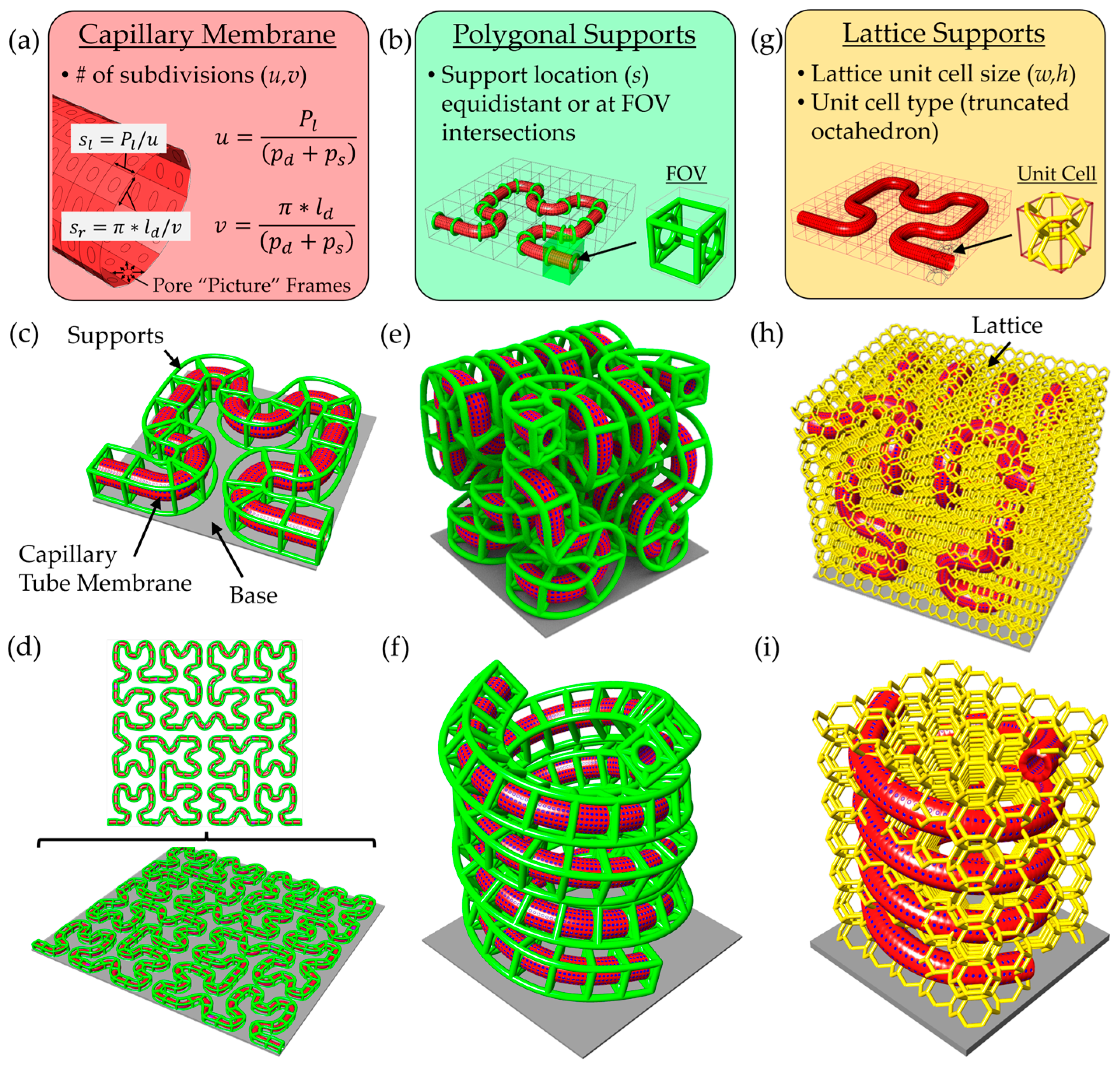
To generate complex and physiologically relevant microcapillary geometries, we developed a versatile scaffold design pipeline using modeling software made by Rhinoceros 3D called Rhino 7 along with a plugin called Grasshopper. This platform enables rapid generation of microcapillary models along arbitrary paths, with tunable parameters including lumen diameter, pore diameter, pore spacing, wall thickness, and support beam thickness. Microcapillary paths are imported from comma-separated value (.csv) files containing 3D coordinates, which define a Non-Uniform Rational B-Spline (NURBS) curve used as the central axis of the capillary geometry. Pores in the surface of the microcapillary’s cylindrical lumen are created using mesh-based operations rather than traditional model tree-based CAD modeling. A parametric domain subdivision of the cylindrical capillary surface sets the spacing and location of pores (
Figure 1a).
Two equations control the pore distribution along the capillary tube surface, including:
where
u in Equation (1) defines the number of subdivisions along the capillary tube path length (
Pl) based on the desired pore diameter (
pd) and desired pore spacing (
ps). Similarly,
v in Equation (2) defines the number of subdivisions in the circumferential direction for the desired lumen diameter (
ld), pore diameter, and pore spacing. Therefore, the side lengths of each surface subdivision are determined using the following:
where Equation (3) defines the length along the capillary membrane path direction (
sl), and Equation (4) defines the length along the capillary membrane circumferential direction (
sr). A frame enclosing each pore is created using
Weaverbird’s Picture Frame function, with an offset thickness stipulated by the user. The offset thickness of the frame was set equal to half the pore separation distance to generate a pore with the desired diameter. After this step the mesh is thickened to desired capillary membrane thickness and smoothed using
Weaverbird and
Catmull–Clark functions.
To suspend the capillary membrane off the printing substrate, we implemented two scaffold support strategies: polygonal support and lattice-based support structures. The polygonal support method adds beams arranged in polygon shape around the capillary, connected via diagonal struts to a circular collar that wraps around the perimeter of the capillary. Users can define support spacing, polygon type, and rotational offset. Supports may be uniformly distributed or strategically placed at predicted field-of-view (FOV) transitions based on the TPL system’s lens and slice settings (
Figure 1b). A Hilbert curve-based microcapillary illustrates this method, with green support beams placed at FOV intersections (
Figure 1c). The design platform is scalable, easily accepting larger and more complicated 2D paths (
Figure 1d). Examples of 3D configurations using this support strategy are shown, including Hilbert curves (
Figure 1e) and double helices (
Figure 1f).
However, this approach relies on the connection at the bottom to the base and cannot fully support arbitrary 3D curves. To address this, we employed a lattice-based strategy using a voxelized bounding box generated via the Crystallon plugin (
Figure 1g), which ensures the connections among all unit cells at the box boundary. A truncated octahedron unit cell was selected for its high porosity and structural connectivity. Importantly, lattice beams intersecting the capillary volume were removed using the
PointInBrep function, and the remaining struts were converted to solid pipe Brep objects with rounded caps, rendered in gold color. This support method not only enables fabrication of complex 3D geometries but also promotes 3D cellular integration. Examples using 3D Hilbert and double-helix capillaries demonstrate the method’s capabilities (
Figure 1h,i). This flexible approach facilitates rapid tuning of architectural complexity, microcapillary spacing, and spatial coverage for a range of in vitro tissue modeling applications.
2.2. TPL Materials and Resin Preparation
OrmoComp (Micro Resist Technology GmbH, Berlin, Germany) and IP-PDMS (Nanoscribe GmbH, Eggenstein-Leopoldshafen, Germany) resins were used as received from the manufacturers. These materials provided rigid and elastomeric mechanical properties, respectively, and were used to fabricate scaffold regions requiring high geometric fidelity (OrmoComp) or flexible, tissue-mimicking characteristics (IP-PDMS).
PEGDA with a molecular weight of 700 kDa (PEGDA 700, Sigma-Aldrich, St. Louis, MO, USA) was selected as a moderately stiff material to balance geometric stability and biological relevance. PEGDA 700 was filtered through a MEHQ column filter (Sigma-Aldrich, St. Louis, MO, USA) to remove polymerization inhibitors, then mixed with 1% w/v Irgacure 819 photoinitiator (Sigma–Aldrich, St. Louis, MO, USA). The mixture was vortexed at 2500 rpm for 1 min to ensure homogeneity. Air bubbles were removed by vacuum degassing prior to TPL printing.
By combining rigid, intermediate, and elastomeric resins, this material system allowed tuning of scaffold mechanical properties and supported fabrication of perfusable microcapillary scaffolds for versatile cell culture applications.
2.3. TPL Fabrication of Microcapillary Designs
Microcapillary scaffolds were fabricated using TPL to achieve high-resolution, geometrically precise structures suitable for integration into microfluidic platforms. Scaffold models, including capillaries, support lattices, and base geometries, were designed in Rhinoceros 3D and exported as STL files. Test scaffolds were initially printed with a range of lumen diameters (40–80 µm), and a 40 µm-diameter capillary chip based on two stacked Hilbert curves was used for structure testing and flow validation. A flat base was added below the scaffold to help ensure adhesion in aqueous conditions.
All scaffold component models were converted to mesh format, and mesh density was reduced by 95% using the ReduceMesh command in Rhino 7 to minimize file size for efficient slicing in DeScribe software (version 2.5.3, Nanoscribe GmbH). The models were then sliced in DeScribe using optimized parameters: a slice thickness of 1.0 µm, hatch distance of 0.2 µm, and six contour lines. Solid infill was applied to ensure structural integrity, and stitching across adjacent fields of view (FOVs) was controlled using a 15° stitching angle and 5 µm overlap to minimize discontinuities.
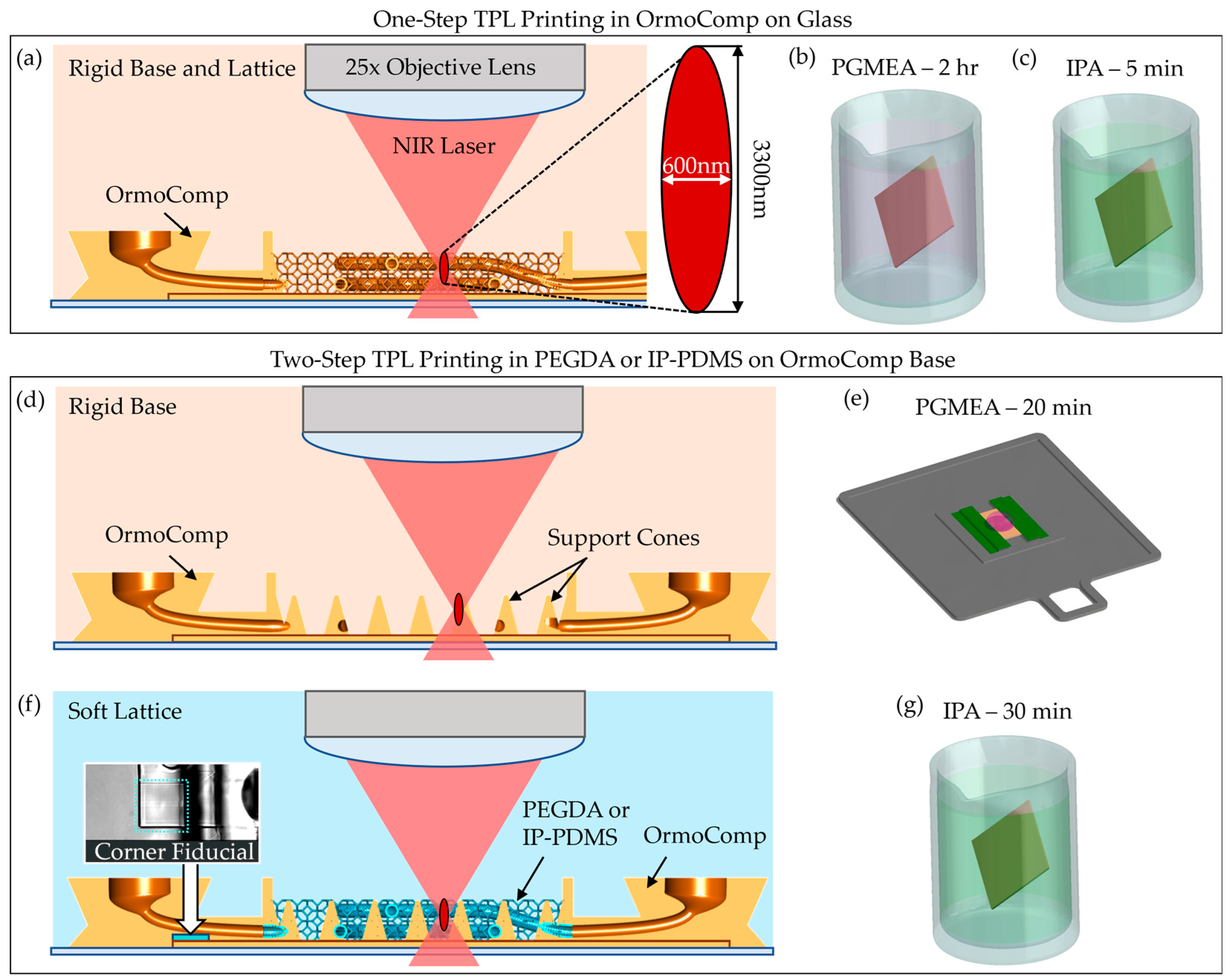
Fabrication was performed on a Nanoscribe Photonic Professional GT+ system (Nanoscribe GmbH, Eggenstein-Leopoldshafen, Germany) equipped with a 25×, NA 0.8 immersion objective, operating in Dip-in Laser Lithography (DiLL) mode with a 780 nm femtosecond laser. A schematic of the DiLL printing process is shown in
Figure 2a. Coverslips (12 mm diameter, No. 2 thickness) were cleaned sequentially with acetone, isopropanol, and deionized water, followed by oxygen plasma treatment. To promote scaffold adhesion, Ormoprime (Micro Resist Technology GmbH, Berlin, Germany) was spin-coated onto the coverslips at 4000 rpm for 1 min and baked at 150 °C for 5 min. The prepared coverslips were taped on all sides onto indium tin oxide (ITO)-coated glass slides for mounting. A focal offset of approximately 200 µm (glass slide thickness) was applied to target the focal plane ~8 µm inside the coverslip, ensuring uniform adhesion and printing consistency across the sample.
In TPL, a near-infrared (NIR) femtosecond laser is tightly focused to induce two-photon absorption in the resist. At the focal point, the simultaneous absorption of two photons initiates local crosslinking, forming a hardened voxel with a diameter of approximately 600 nm in the short axis and 3300 nm in the long axis [
30]. Printing parameters were adjusted based on the material properties. For OrmoComp scaffolds, printing was conducted using a laser power of 40 mW and a scan speed of 80 mm/s. After printing, the structures were developed in a propylene glycol monomethyl ether acetate (PGMEA, VWR, Radnor, PA, USA) bath for 2 h, followed by a 5 min rinse in isopropanol (IPA, VWR, Radnor, PA, USA) (
Figure 2b,c).
For soft materials, including PEGDA 700 and IP-PDMS, a dual-material develop-in-place workflow was implemented to prevent collapse during printing and post-processing. Initially, OrmoComp base structures with integrated nozzle ports were printed directly onto the coverslip and developed in PGMEA for 20 min, rinsed with IPA, and dried with nitrogen (
Figure 2d,e). A large droplet of OrmoComp was required to avoid bubble forming in the second layer of the 3D-printed structure.
Next, PEGDA 700 or IP-PDMS resin was manually dispensed onto the developed OrmoComp base. Air bubbles were carefully removed with forceps to avoid potential printing defects. The sample was reloaded into the Nanoscribe system, and the objective was manually realigned using recorded focal height offsets. The alignment was further fine-tuned by printing fiducial marks at the corner of the scaffold to ensure accurate overlay (inset of
Figure 2f). Capillary networks and lattice supports were then printed directly on the OrmoComp base, which contains cone structures strategically printed on the base to provide distributed support of the soft scaffolds. PEGDA 700 was printed using a laser power of 50 mW and a scan speed of 74 mm/s, while IP-PDMS was printed using a laser power of 40 mW and a scan speed of 50 mm/s.
Upon completion, scaffolds printed in PEGDA and IP-PDMS were developed in IPA for 30 min to remove uncrosslinked resin and air dried (
Figure 2g). This dual-material fabrication process successfully integrated rigid and soft polymers into single scaffolds, enabling complex geometries with enhanced mechanical robustness while supporting soft capillary networks that resisted collapse during solvent development.
2.4. Microfluidic Interface
To establish perfusion through the TPL-printed microcapillary scaffolds, a modular microfluidic interface was engineered. This system utilized polyolefin heat-shrink tubing (McMaster-Carr, Douglasville, GA, USA) and 22-gauge hypodermic needles (Careach Direct, Seattle, WA, USA) to provide a compact, scalable, and cost-effective alternative to bulky commercial connectors that are often incompatible with delicate microscale architectures.
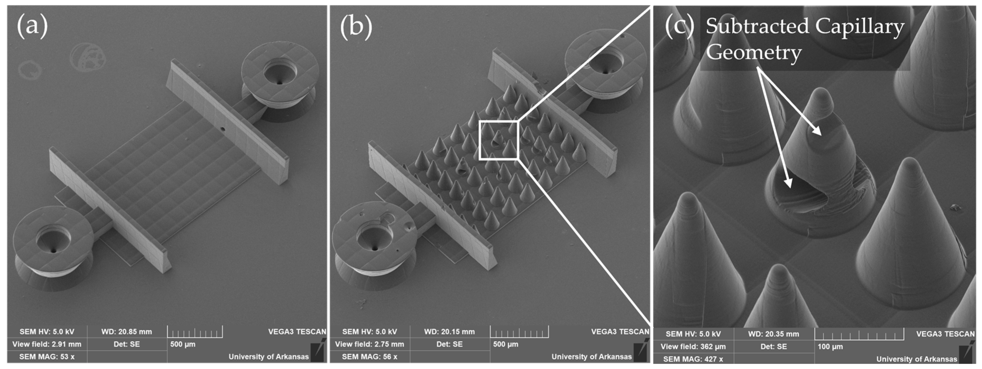
The assembly process is shown in
Figure 3a–c. Vertical nozzle ports were designed directly into the OrmoComp scaffold base and were optimized to mate with 0.020-inch inner diameter heat-shrink tubing (
Figure 3a). Following scaffold development, the tubing was manually fitted onto the nozzle ports and locally heated using a soldering iron for 1–2 s. This heating step caused the tubing to contract, creating a tight, press-fit seal against the nozzle surfaces (
Figure 3b). To further secure the connection and prevent leakage, OrmoComp resin was applied around the tubing at the junction. A retaining wall was used to prevent resin from spreading into the microvasculature. The resin was cured under ultraviolet (UV) light at 100 mW/cm
2 for 1 min (
Figure 3c).
The entire assembly was then secured to the bottom of a standard 12-well plate using a small drop of OrmoComp resin, which was UV-cured to anchor the chip firmly in place. A custom 3D-printed holder was affixed to the top of the well using UV-cured OrmoComp. The top–down view is shown in
Figure 3d, and the side view of single well is shown in
Figure 3e. This holder included ports for two blunt 26-gauge hypodermic needles (Careach, 0.5-inch length), enabling external media exchange during experiments.
Flow system integration was achieved by inserting blunt 22-gauge hypodermic needles into the exposed ends of the heat-shrink tubing. After insertion, the heat-shrink tubing was locally heated with a soldering iron to shrink tightly around the needles, ensuring robust mechanical engagement. OrmoComp resin was then applied around the needle-tubing junction and UV-cured (100 mW/cm2, 1 min) to complete a leak-free seal.
The chip was covered with a removable 12 mm-diameter glass lid to fully enclose the chamber and maintain sterility. For perfusion experiments, the assembled device was connected via flexible tubing to a syringe pump operated in a push–pull configuration, allowing controlled, bidirectional flow through the scaffold (
Figure 3f). This setup minimized pressure fluctuations and ensured gentle, continuous perfusion compatible with neurovascular models. An in situ imaging system (Etaluma LS560 microscope (Etaluma, San Diego, CA, USA) equipped with a custom 3-axis stage) was used to monitor perfusion in real time without disrupting incubator conditions (
Figure 3e).
2.5. Sterilization and Scaffold Presoak
To ensure biocompatibility and minimize cytotoxic effects from fabrication residues, all microfluidic chip components underwent rigorous sterilization and presoak protocol prior to biological testing. This two-stage process was designed to remove leachable contaminants and condition scaffold surfaces for optimal cell interaction.
All chip materials, including TPL-printed scaffolds (OrmoComp, PEGDA 700, and IP-PDMS), heat-shrink tubing, 3D-printed parts (Siraya Tech Blu, Anycubic Transparent Green, and PLA), and tissue culture plastics, were sterilized for viability testing. All materials were first rinsed with 70% ethanol for 2 m. After air-drying in a laminar flow hood for 30 min, the materials were exposed to germicidal ultraviolet (UV) light for 1.5 h.
Following sterilization, a prolonged presoak process was implemented to further reduce potential cytotoxic leachates, such as residual photoinitiators and unreacted monomers. During the initial 2 days (Days 0–1), chips were rinsed at 1-h intervals for 3 h with phosphate-buffered saline (PBS) to remove soluble impurities. From Days 2 to 6, chips were washed daily and incubated in complete neural growth medium to allow surface equilibration and passivation. This presoak stage was critical for minimizing acute cytotoxic responses upon subsequent cell seeding.
The neural growth medium used during presoak was formulated to support neural stem cell health. It consisted of basal medium (Vesta Biotherapeutics, formerly Phoenixsongs Biologicals, Branford, CT, USA) supplemented with Neural StemCell Growth Base Supplement, laminin, basic fibroblast growth factor (bFGF), epidermal growth factor (EGF), and a proprietary neural culture factor. Gentamicin (37.5 mg/L, St. Louis, MO, USA) was included to prevent microbial contamination during extended incubation. All media components were sterile filtered using a 0.22 µm membrane and stored at 4 °C prior to use.
2.6. Surface Coating
To enhance cellular adhesion and prepare scaffold surfaces for neural cell culture, a sequential coating protocol using poly-D-lysine and laminin was applied. This approach improved scaffold biocompatibility and mimicked essential extracellular matrix features.
Scaffolds and controls (tissue culture plastic) were first incubated in a 5 µg/mL solution of poly-D-lysine (Thermo Fisher Scientific, Waltham, MA, USA) for 10 min at room temperature. This cationic polymer increases surface charge and promotes initial cell adhesion on synthetic and hydrogel-based materials. Following incubation, samples were rinsed three times with sterile, cell culture-grade water to remove unbound poly-D-lysine and ensure uniform surface coating.
Next, laminin (Thermo Fisher Scientific, Waltham, MA, USA) was applied at a concentration of 10 µg/mL and incubated for 2 h at room temperature. As a key extracellular matrix protein, laminin supports neuronal attachment, differentiation, and survival, making it critical for creating a cell-compatible microenvironment. After incubation, excess laminin was aspirated and samples were gently rinsed with sterile water to remove residual solution. Culture medium was then added to the wells to maintain hydration and prepare samples for cell seeding. To stabilize the coating and equilibrate the scaffolds to culture conditions, coated samples were placed in a humidified incubator for 1 h prior to cell plating.
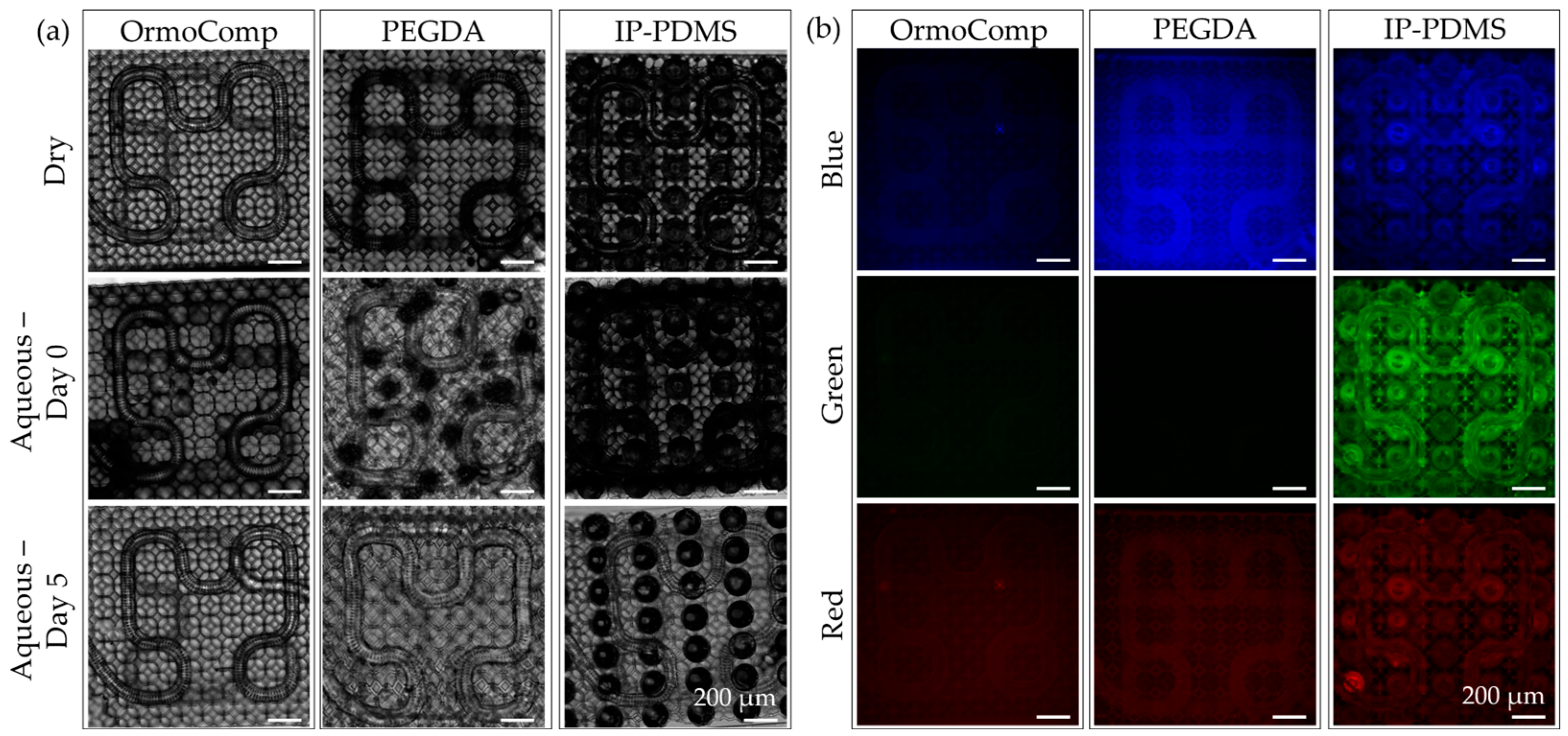
2.7. Cytotoxicity Assay
The cytocompatibility of TPL materials and associated microfluidic chip materials was evaluated using a Live/Dead® viability assay (Thermo Fischer Scientific, Waltham, MA, USA) with human hippocampal-derived neural stem cells (hNSCs; HIP-009, Vesta Biotherapeutics, Branford, CT, USA). These cells, chosen for their sensitivity to material-induced toxicity and relevance to neurobiological studies, provided an effective model for assessing material suitability for brain-on-chip applications.
Cells were seeded directly onto TPL materials (OrmoComp, PEGDA 700, and IP-PDMS) molded flat with a PDMS stamp and cured under 100 mW/cm2 UV for 5 min, chip materials (heat-shrink tubing and wells with hypodermic needle holder lids) and control substrates immediately after thawing from cryopreservation at a density of 4.5 × 10⁵ cells per well. Non-adherent cells and debris were removed by media exchange on Day 1 to ensure uniform attachment. Cultures were then maintained without further media changes until Day 3 under static conditions.
At the conclusion of the culture period, viability was assessed using the Live/Dead assay, which differentiates live and dead cells by fluorescence. Calcein AM (2 µM, Ex: 484 nm, Em: 517 nm) labeled viable cells green, while ethidium homodimer-1 (4 µM, Ex: 528 nm, Em: 617 nm) stained non-viable nuclei red. Samples were incubated in staining solution for 20 min at 37 °C before imaging.
Fluorescence imaging for cytotoxicity assay and scaffold material fluorescence analysis was performed on an Olympus IX-70 inverted microscope (Olympus, Center Valley, PA, USA) equipped with filter cubes: U-MNUA2 for blue (Ex: 365 nm, Em: 440 nm), U-MNIBA3 for green (Ex: 480 nm, Em: 530 nm), and U-MRFPHQ for red (Ex: 545 nm, Em: 597 nm) (Hunt Optics, Pittsburgh, PA, USA). Images were captured using a CoolSnap K4 camera (Photometrics, Huntington Beach, CA, USA) controlled by MicroManager software (version 1.4.23). Exposure times were standardized to 1000 ms across all channels to ensure consistency.
Quantitative analysis was conducted by imaging three independent regions per sample at 4× magnification, yielding nine images per material group. Images were processed using a custom MATLAB (2024a) script for automated segmentation and initial cell counting. The script utilized imbinarize() and label2rgb() functions to identify live and dead cells from fluorescence images. This was followed by manual correction with a secondary script to verify accuracy. The correction script utilized the ginput() function to provide the user with a graphical user interface (GUI) to correct live cells marked dead, dead cells marked live, and live or dead cells that were missed in the automatic count. In total, viability calculations were based on approximately 116,000 cells.
2.8. PEGDA Mechanical Property Characterization
While mechanical data for OrmoComp and IP-PDMS produced by TPL are available in the literature, equivalent characterization for PEGDA 700 formulated with 1% Irgacure 819 photoinitiator had not been reported. As this formulation was specifically utilized for nanoprinting in this study, direct measurement of its mechanical properties was necessary.
Test specimens were printed using TPL as square prisms (200 µm × 200 µm × 10 µm) onto methacrylate-treated glass coverslips (3 h in 3-(Trimethoxysilyl)propyl methacrylate, Sigma-Aldrich, St. Louis, MO, USA) to ensure adhesion during testing. Nanoindentation was conducted under ambient conditions using a Hysitron TriboIndenter (Bruker, Eden Prairie, MN, USA) equipped with a spheroconical diamond probe (5 µm tip radius). A linear load–unload rate of 10 µN/s was applied up to a peak load of 250 µN, with a 5 s hold at maximum load.
The Young’s modulus and hardness of PEGDA 700 were calculated based on the nanoindentation load-displacement curves using the Oliver–Pharr method [
31]. Reported values reflect the mean ± standard deviation from three indentations.
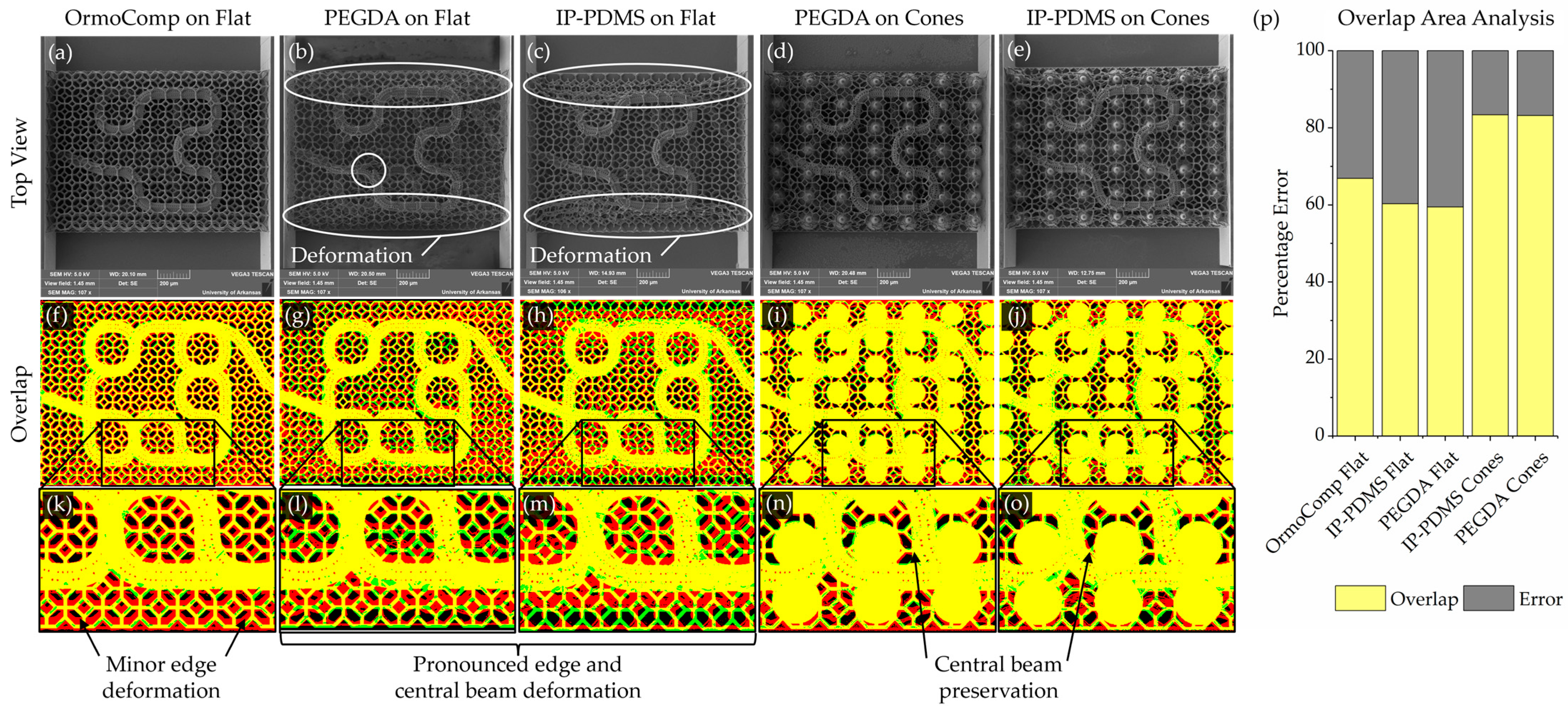
2.9. Geometry Registration Analysis
A geometry registration analysis was performed to quantitatively assess scaffold fidelity by comparing fabricated structures to their original digital designs. Deviations were expected to arise from two sources: inaccuracies in the printing process and structural deformation during post-fabrication steps (such as solvent development and drying). As imaging was performed only after development, the measured deviations reflect the combined contributions of both factors.
Binary reference masks representing the intended geometries were generated from the original design files. Top–down renders of scaffold models were exported from Rhinoceros 3D and processed in ImageJ (version 1.54g) to produce binarized black-and-white target images. These served as the reference standard for assessing print fidelity.
Experimental masks were created from scanning electron microscopy (SEM, Vega3, Tescan, Warrendale, PA, USA) images of the printed scaffolds. SEM images were first aligned and cropped using the flat features on the edge of the scaffolds as a repeatable reference. SEM images were then processed to enhance feature visibility, including a global contrast enhancement of 30%. For regions with faint features, particularly at the image edges, localized adjustments were manually applied to improve clarity. The processed images were then binarized to isolate capillary membrane and lattice structures.
To address areas where thresholding alone did not sufficiently capture scaffold features, edge detection using the “Find Edges” function in ImageJ was combined with manual editing to fill in missing regions. Cone support structures were digitally subtracted to ensure that only relevant scaffold features remained for analysis.
Target and experimental masks were then merged using color channels to generate composite registration maps. The target design was assigned to the green channel and the experimental print to the red channel. Therefore, in the resulting maps, yellow indicated overlapping features, green indicated missing scaffold material, red indicated deformed printed material, and black indicated void regions. The overlapping areas were analyzed. This registration method allowed systematic evaluation of printing fidelity, capturing combined deviations resulting from both printing imprecision and post-processing deformation.
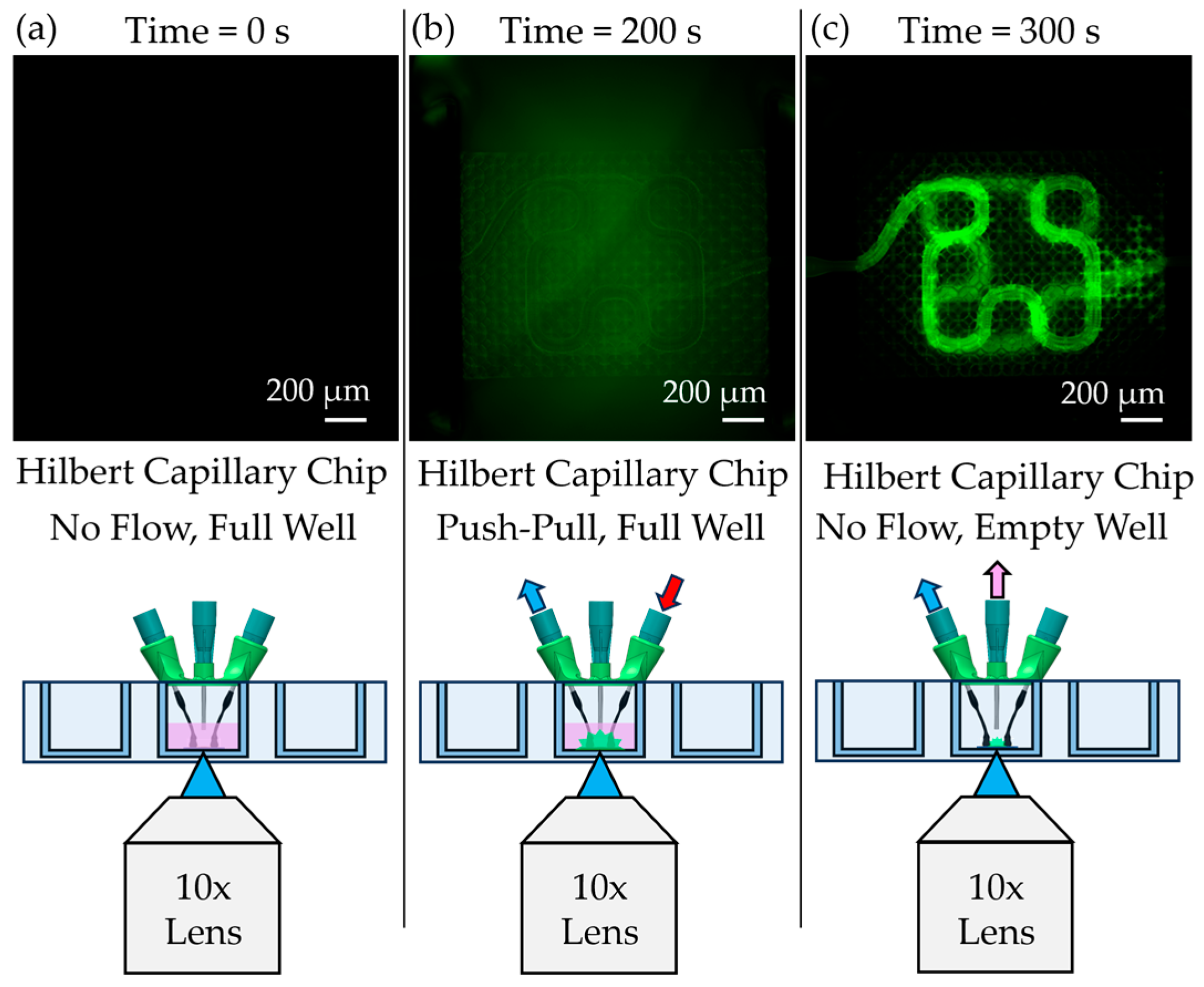
2.10. Diffusion and Particle Flow Testing
Functional testing of the assembled chips was conducted using fluorescein-labeled Dextran (Thermo Fischer Scientific, Waltham, MA, USA) and 1 µm fluorescent polystyrene beads (Sigma-Aldrich, St. Louis, MO, USA). For diffusion experiments, Dextran in phosphate-buffered saline (PBS) was perfused through the capillary scaffolds using a syringe pump (Pump Systems Inc., Franklin, NH, USA) configured with an auxiliary syringe holder to enable push–pull flow (
Figure 3f). A peristaltic pump (Ismatec, Hood River, OR, USA) was used to circulate medium in the external chamber surrounding the scaffold. The syringe pump was operated at a flow rate of 1 µL/min, and diffusion across the capillary membrane was imaged in situ using an Etaluma LS560 microscope. The camera exposure time was set to 5.1 ms to match calibration conditions for Dextran fluorescence.
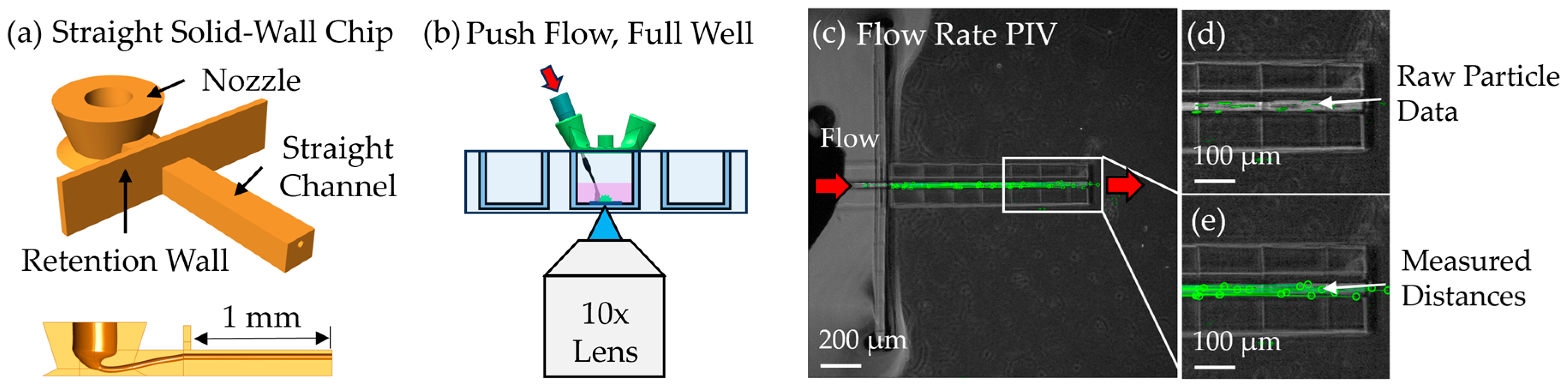
To assess flow speed, particle image velocimetry (PIV) was performed by perfusing 1 µm green fluorescent beads through a 1 mm-long solid-walled channel with a 40 µm diameter—equivalent to the lumen geometry of the scaffold. This open-channel configuration was used to avoid clogging observed in earlier scaffold-based attempts. Beads were suspended in water and driven through the channel at 10 nL/min using the same syringe pump in unidirectional push mode. Timelapse videos were acquired and analyzed using a custom MATLAB script utilizing the ginput() GUI to extract bead trajectories between individual video frames and calculate flow velocity by dividing by the camera exposure rate.
4. Discussion
This work advances the design and fabrication of microfluidic chips with embedded microvasculature scaffolds using TPL, addressing key challenges in generating physiologically relevant vascular structures. Compared to conventional CAD workflows, the mesh-based modeling strategy implemented in Rhinoceros 3D provided an efficient and flexible approach for creating complex scaffold geometries suitable for biological applications. By enabling rapid design iteration and integration of user-defined pore architectures and supports, this workflow streamlined the fabrication of customized vascular networks.
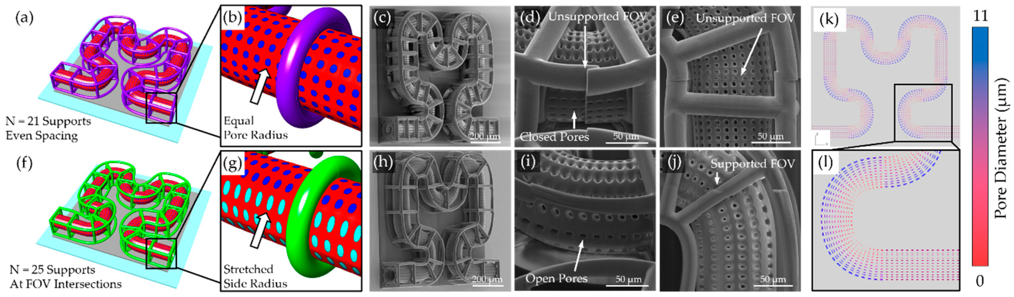
A persistent challenge in TPL fabrication of microcapillary scaffolds is maintaining open-pore architectures, particularly along curved surfaces and scaffold edges. Due to the anisotropic voxel dimensions of TPL, pores facing lateral directions are especially prone to closure during printing. In this study, these limitations were addressed by elongating holes of the subsurfaces on the sides of the capillary membranes, effectively preserving side-facing pore openings and improving overall printing fidelity. Additionally, support strategies were critical for maintaining scaffold integrity throughout printing and post-processing. Polygonal support rings were sufficient for planar capillary designs but were inadequate for more complex geometries. Placement of lattice nodes at FOV stitching boundaries proved effective for reducing misalignment and ensuring seamless scaffold fabrication. In contrast, lattice supports, optimized for fully 3D scaffolds, provided distributed contact points that enhanced structural robustness and minimized deformation at the FOV intersections. The lattice supports were insufficient to provide structural stability for softer print materials such as PEGDA 700 and IP-PDMS. PEGDA 700 was shown to deform initially in an aqueous environment. PEGDA 700 has been shown to soften significantly in aqueous conditions, reducing from the measured modulus of 30.7 MPa down to a reported 0.5–5 MPa [
35]. This softening is likely responsible for the initial geometry change and deformation. IP-PDMS also has a lower reported elastic modulus (350 kPa–17.5 MPa), ultimately leading to deformation if left unsupported [
33]. In contrast, the mesoscale cone supports, printed in OrmoComp, offered robust structural reinforcement, enabling successful fabrication of 3D capillary architectures even with soft materials. Both PEGDA and IP-PDMS demonstrated strong adhesion to the OrmoComp base, establishing a rigid interface that effectively anchors the soft TPL-printed scaffolds.
The ability to realize complex 3D capillary geometries using additive fabrication offers distinct advantages over existing subtractive and planar fabrication approaches. Previous studies relying on planar TPL geometries or subtractive methods, such as ablating hydrogels to create channels, are inherently limited in spatial complexity and integration potential. In contrast, the additive approach demonstrated here enables freeform capillary architectures to be fabricated directly within microfluidic devices without reliance on sacrificial layers or extensive assembly. This capability opens opportunities for more advanced 3D cell culture models, as cells can migrate into and interact with the scaffold lattice, potentially guiding cellular organization and enhancing physiological relevance. Furthermore, by reducing the use of PDMS relative to conventional microfluidic chips, this system avoids small molecule leaching issues and creates a more biochemically compatible environment for sensitive biological assays.
A novel microfluidic interfacing strategy was also developed, utilizing heat-shrink tubing and hypodermic needles to produce reliable and low-cost connections between the external fluidic system and the printed scaffold. This approach eliminated the need for bulky adapters and enabled a compact chip design. SEM analysis confirmed that the heat-shrink tubing formed tight seals without intruding into the scaffold lattice regions, preserving perfusion pathways. Perfusion experiments, performed using a push–pull syringe pump and PIV analysis, validated the suitability of this system for future cell studies.
OrmoComp, PEGDA 700, and IP-PDMS all supported hNSC adhesion and viability, each exceeding 70% viability after 3 days in culture. Among the peripheral chip components, PLA lids demonstrated good compatibility, supporting healthy cell attachment and viability comparable to standard culture substrates. In contrast, LCD 3D-printed resins used for chip lids, despite not contacting the media directly, exhibited significant cytotoxicity, likely due to volatile compound release or insufficient post-curing. Although Siraya Tech Blu resin nominally meets ISO 10993-5 biocompatibility standards [
36], the curing conditions applied in this study proved inadequate. These findings underscore that even non-contact components must be carefully evaluated to avoid adverse effects on sensitive neural cultures.
5. Conclusions
In this study, we developed a versatile and modular platform for fabricating perfusable microvascular scaffolds integrated within microfluidic chips using TPL. Leveraging mesh-based design, multi-material printing, and an accessible heat-shrink tubing interface, we successfully produced customizable 3D capillary networks with tunable mechanical properties.
Rigid (OrmoComp), moderately stiff (PEGDA 700), and soft elastomeric (IP-PDMS) materials were all successfully printed into a multi-material chip configuration. However, PEGDA 700 and IP-PDMS printed structures suffered from deformation after development, requiring a cone-based support structure to maintain fidelity. Flow validation demonstrated that the printed scaffolds supported perfusion at physiologically relevant flow speeds.
Cytocompatibility assays further confirmed that all TPL-printed scaffold materials supported robust human neural stem cell viability and attachment, validating their suitability for neurovascular and brain-on-chip applications. PLA lids demonstrated suitable biocompatibility, while LCD resin lids exhibited significant cytotoxicity, underscoring the importance of carefully selecting and processing all chip components to ensure compatibility with sensitive biological environments.
Together, these results establish a versatile and adaptable platform for creating biologically relevant 3D vascular scaffolds in microfluidic systems. Future efforts will focus on incorporating brain endothelial cells to create biomimetic BBB models and integrating microcapillary scaffolds into brain organoid systems to promote maturation and reduce necrosis. These advancements will expand the platform’s utility for neurovascular modeling, disease research, and drug transport studies.


