
Biaxial Non-Resonant Electromagnetically Driven Scanning Micromirror with Large Aperture


Abstract
1. Introduction
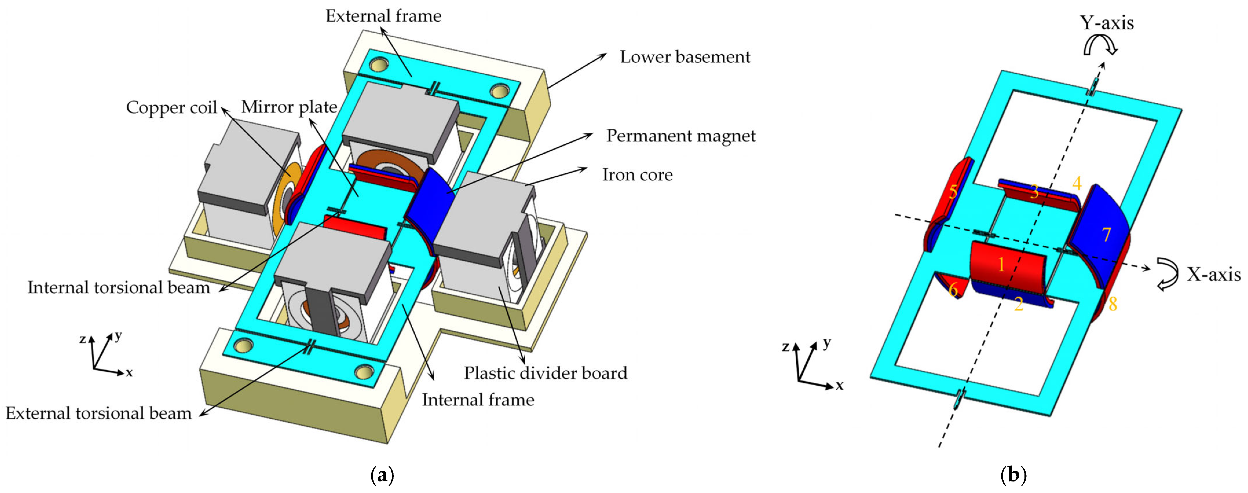
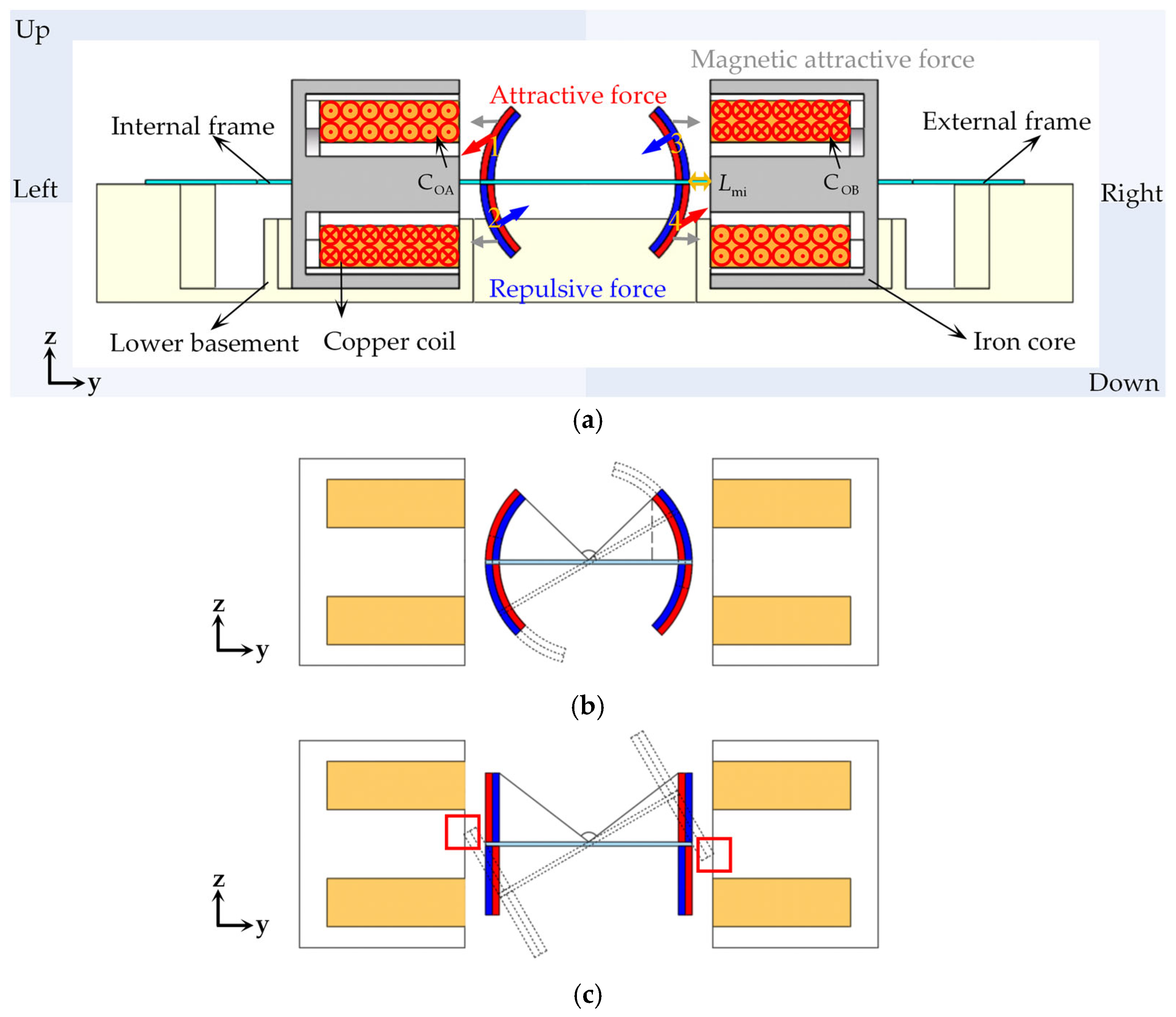
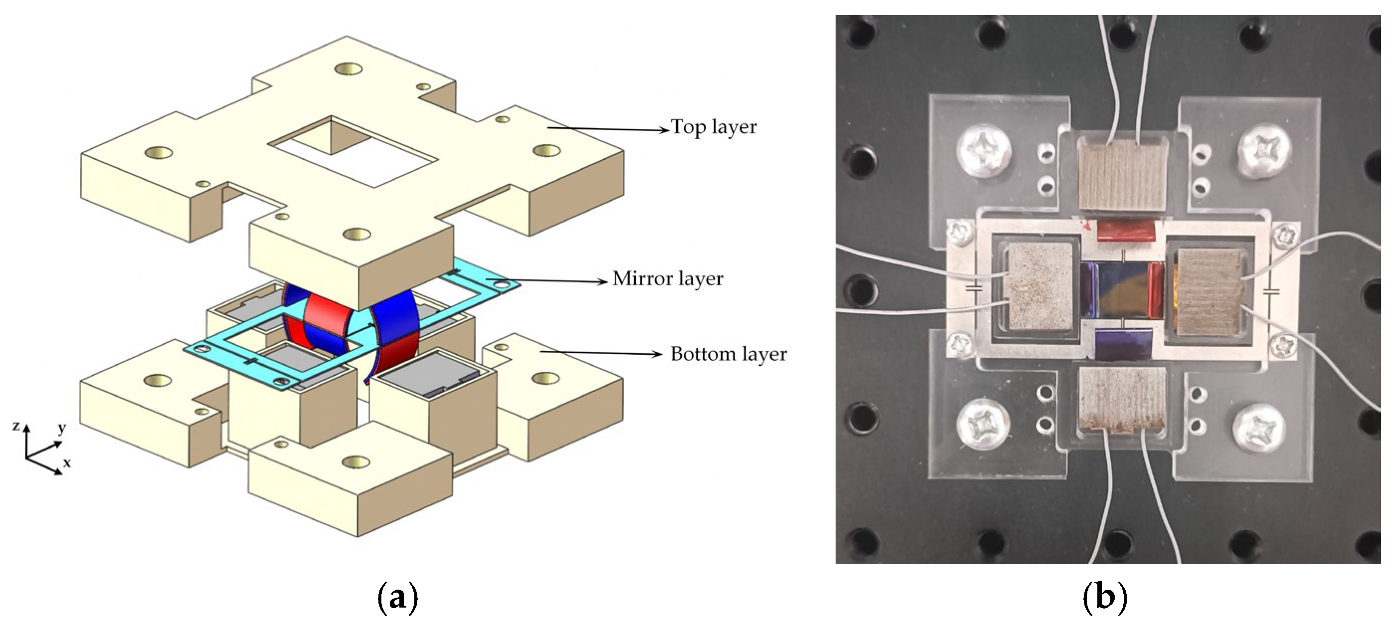
2. Design
3. Modeling and Simulation
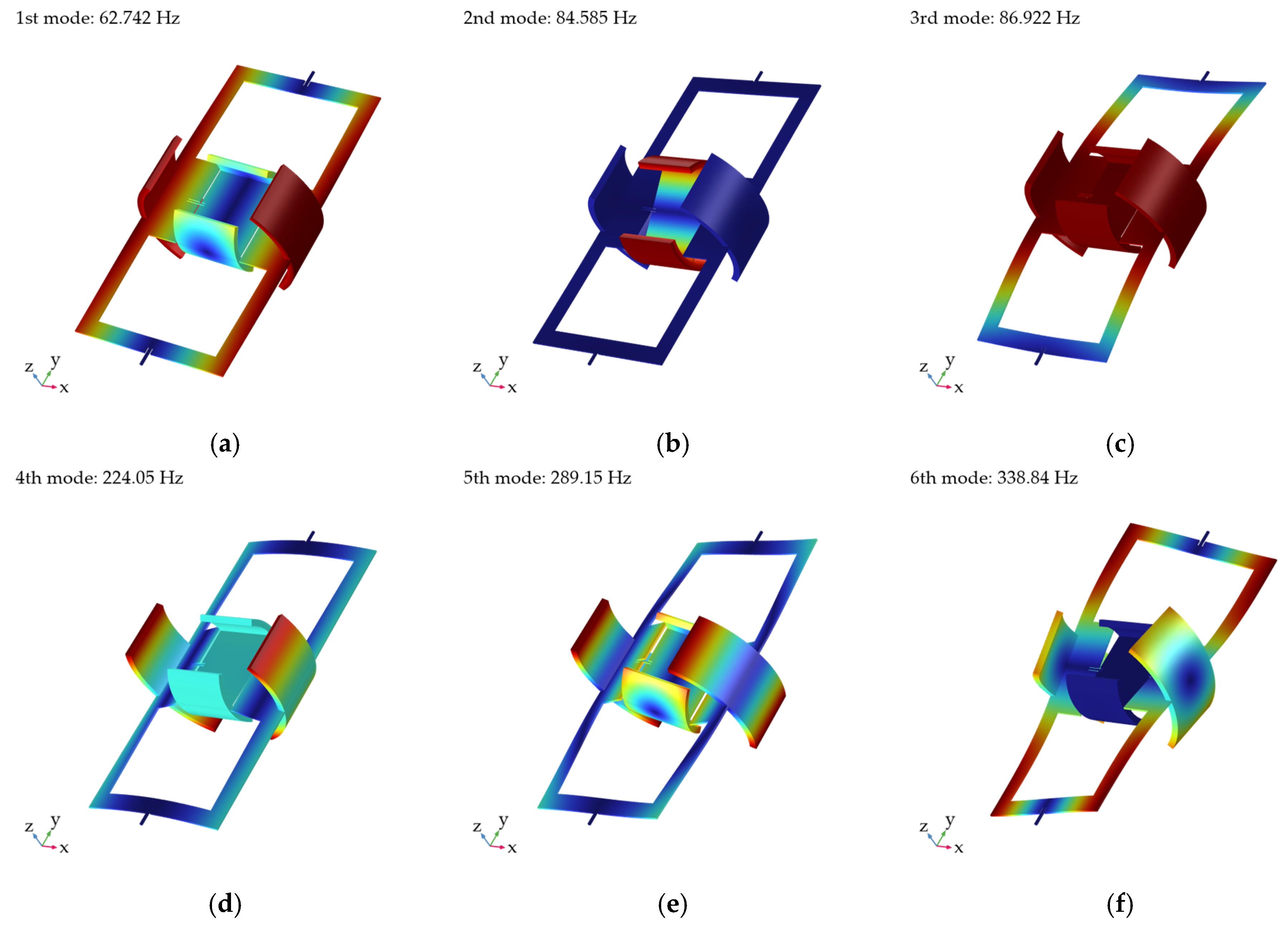
3.1. Dynamic Simulation
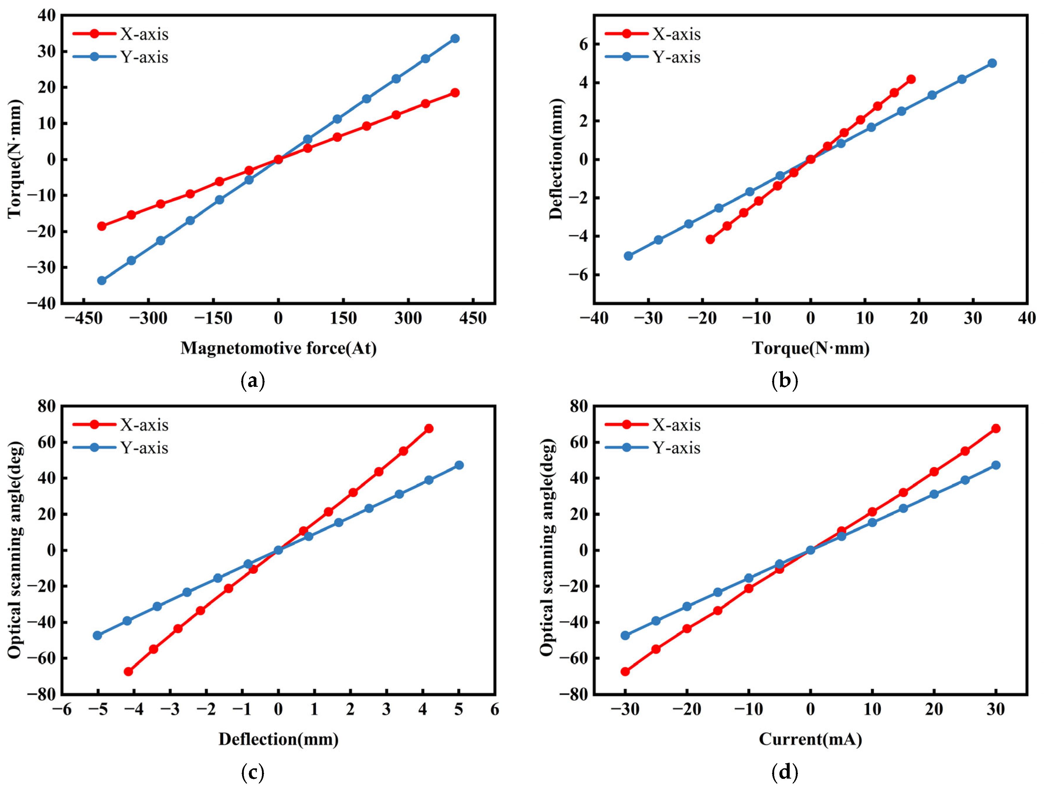
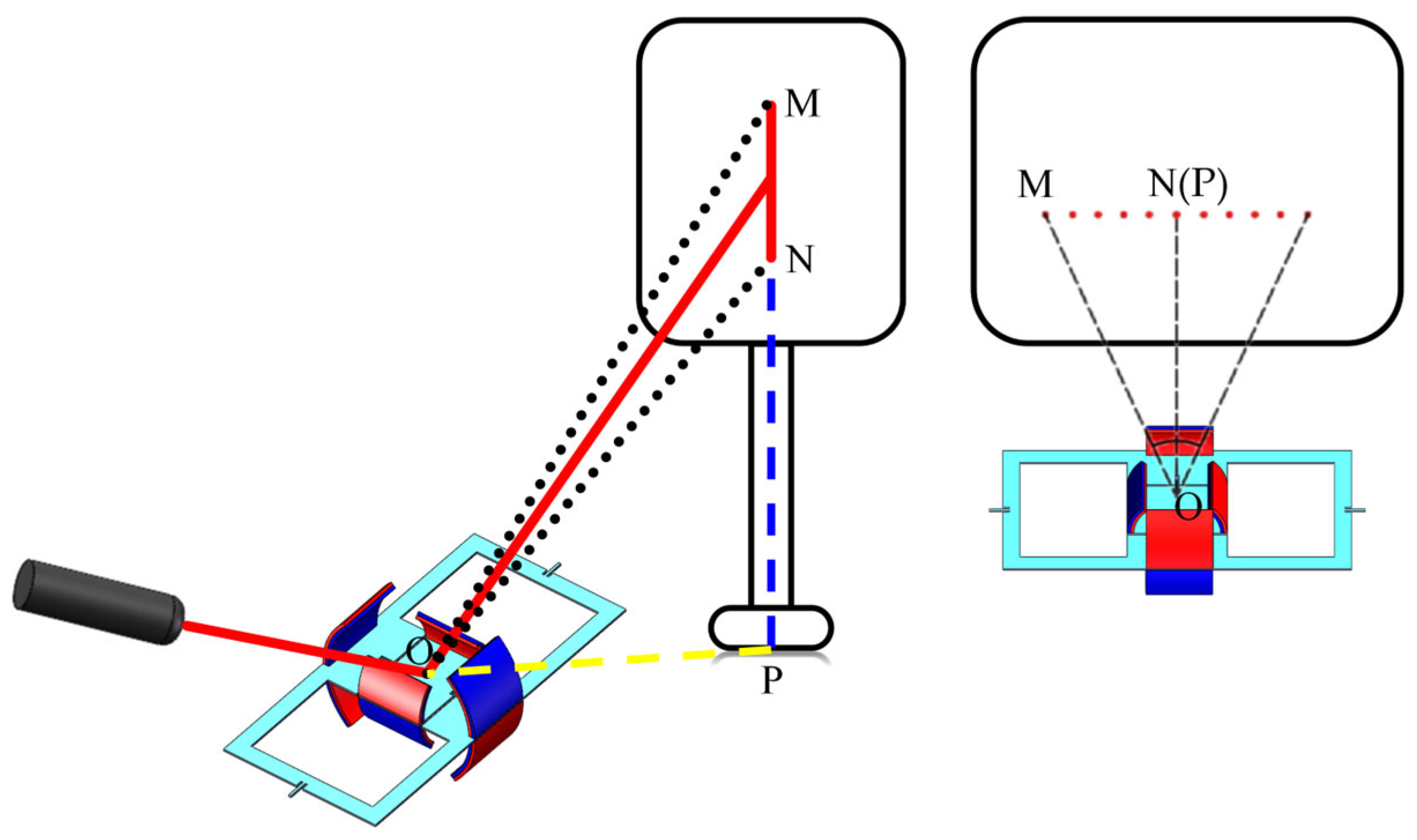
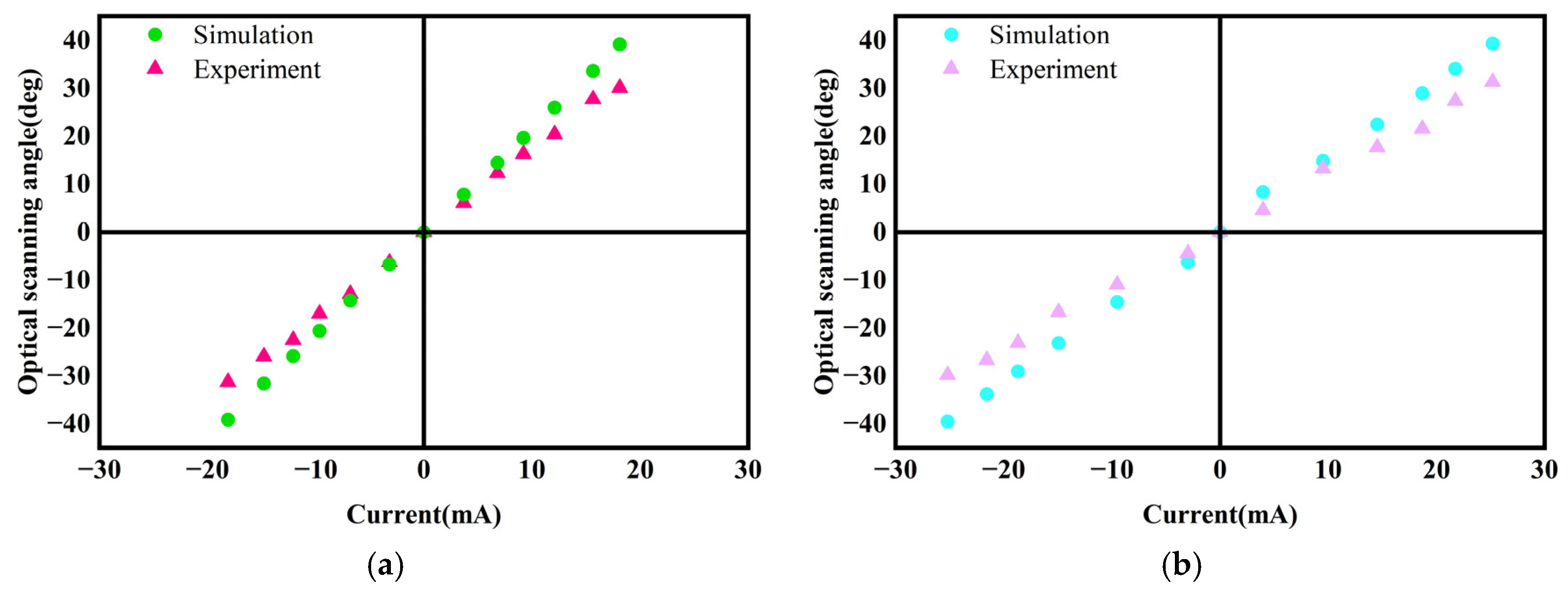
3.2. Optical Scanning Angle Analysis
4. Experiments
4.1. Experimental Setup
4.2. Experimental Results
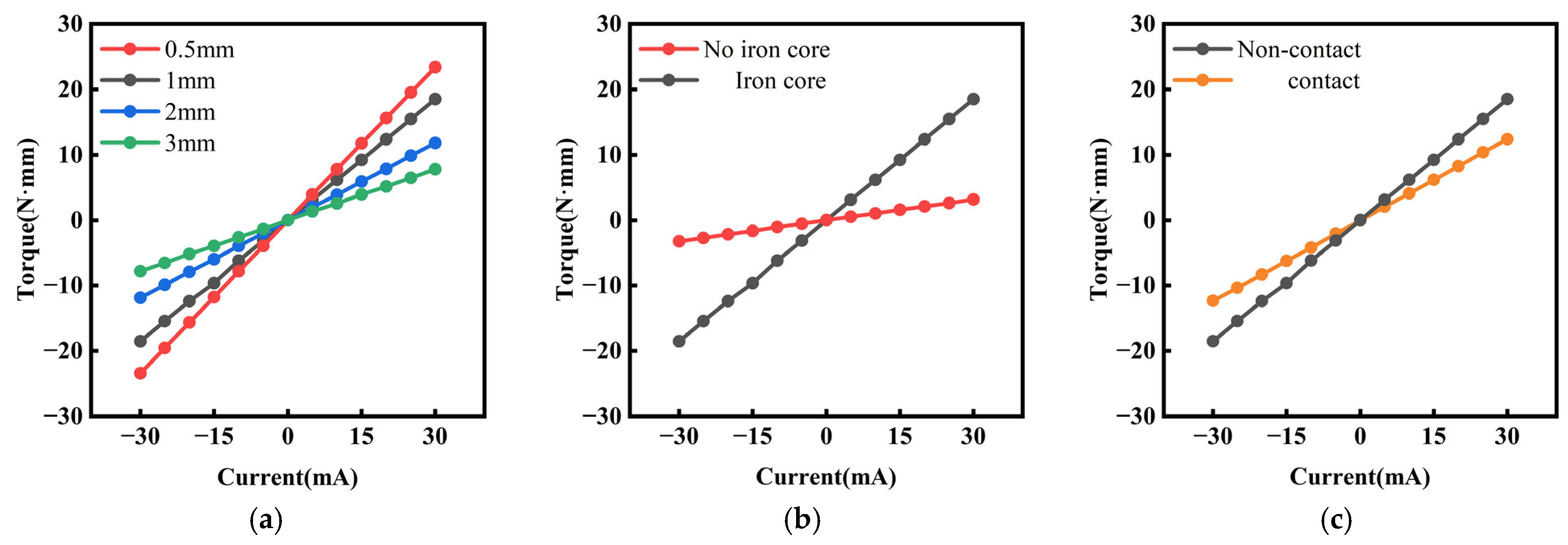
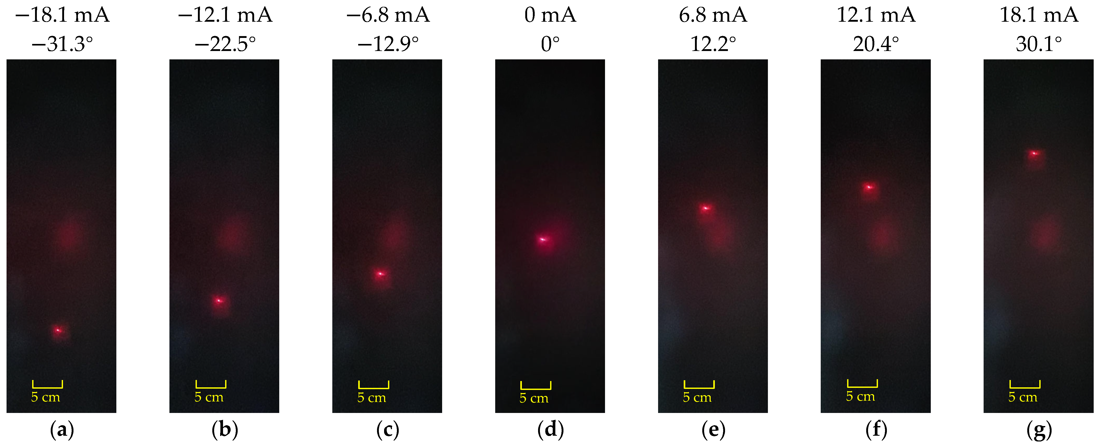
4.2.1. Static Test
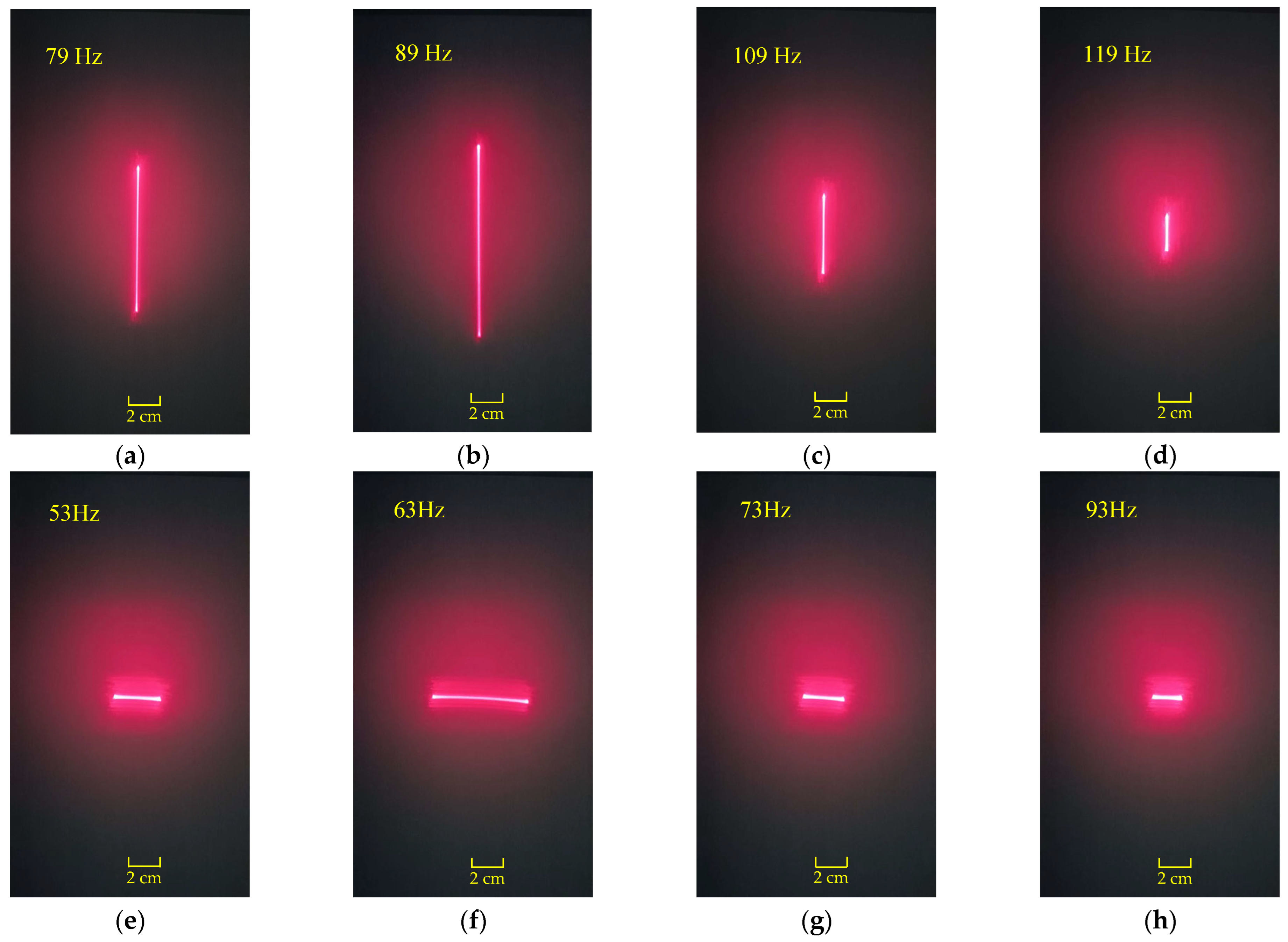
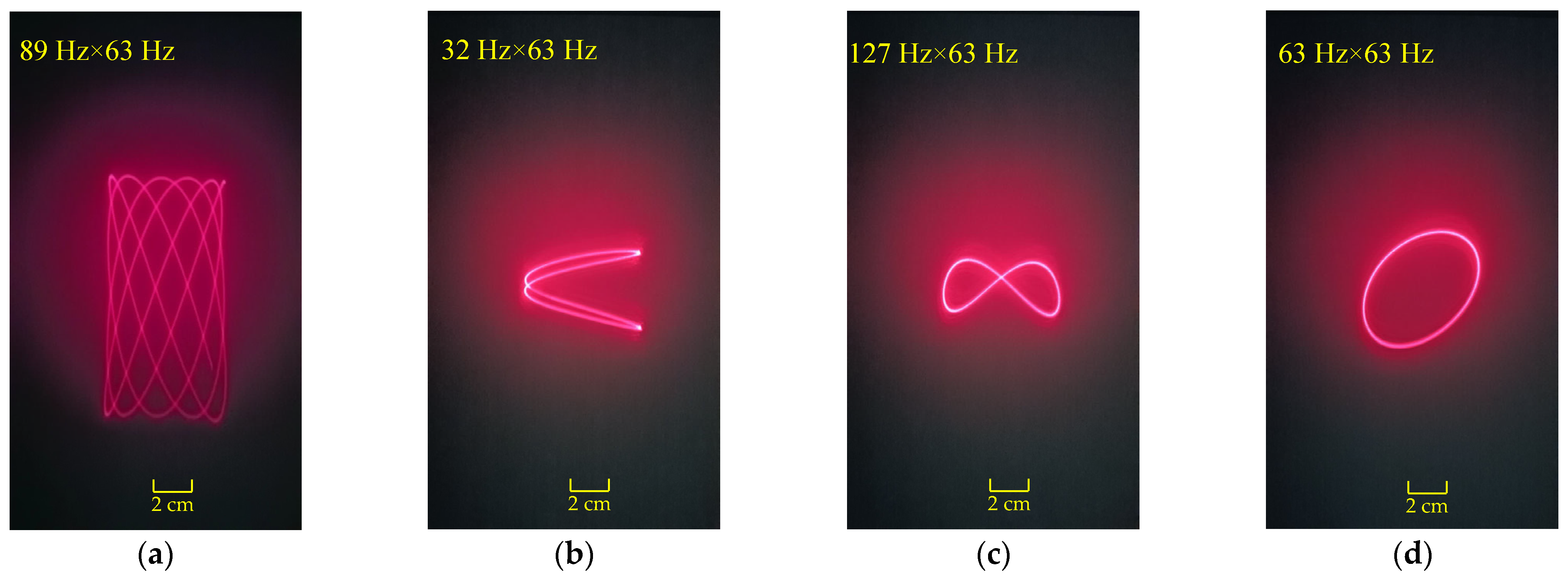
4.2.2. Dynamic Test
5. Discussion
6. Conclusions
Author Contributions
Funding
Data Availability Statement
Conflicts of Interest
References
- Solgaard, O.; Godil, A.A.; Howe, R.T.; Lee, L.P.; Peter, Y.-A.; Zappe, H. Optical MEMS: From Micromirrors to Complex Systems. J. Microelectromech. Syst. 2014, 23, 517–538. [Google Scholar] [CrossRef]
- Milanovic, V.; Kasturi, A.; Hachtel, V. High brightness MEMS mirror based head-up display (HUD) modules with wireless data streaming capability. In Proceedings of the MOEMS and Miniaturized Systems XIV, San Francisco, CA, USA, 9–12 February 2015; Volume 9375. [Google Scholar]
- Kim, S.; Han, Y.G. Suppression of speckle patterns based on temporal angular decorrelation induced by multiple beamlets with diverse optical paths. J. Korean Phys. Soc. 2014, 64, 527–531. [Google Scholar] [CrossRef]
- Sun, J.; Xie, H. MEMS-Based Endoscopic Optical Coherence Tomography. Int. J. Opt. 2011, 2011, 825629. [Google Scholar] [CrossRef]
- Zheng, D.; Wang, D.; Yoon, Y.K.; Xie, H. A Silicon Optical Bench-Based Forward-View Two-Axis Scanner for Microendoscopy Applications. Micromachines 2020, 11, 1051. [Google Scholar] [CrossRef] [PubMed]
- Jung, W.; McCormick, D.T.; Zhang, J.; Wang, L.; Tien, N.C.; Chen, Z. Three-dimensional endoscopic optical coherence tomography by use of a two-axis microelectromechanical scanning mirror. Appl. Phys. Lett. 2006, 88, 163901. [Google Scholar] [CrossRef]
- Piyawattanametha, W.; Barretto, R.P.J.; Ko, T.H.; Flusberg, B.A.; Cocker, E.D.; Ra, H.; Lee, D.; Solgaard, O.; Schnitzer, M.J. Fast-scanning two-photon fluorescence imaging based on a microelectromechanical systems two-dimensional scanning mirror. Opt. Lett. 2006, 31, 2018–2020. [Google Scholar] [CrossRef] [PubMed]
- Milanović, V.; Kasturi, A.; Siu, N.; Radojičić, M.; Su, Y. “MEMSEYE” for optical 3D tracking and imaging applications. In Proceedings of the IEEE TRANSDUCERS 2009 International, Actuators and Microsystems Conference, Beijing, China, 5–9 June 2011; pp. 1895–1898. [Google Scholar]
- Zuo, H.; He, S. Extra Large Aperture FPCB Mirror Based Scanning LiDAR. IEEE/ASME Trans. Mechatron. 2022, 27, 93–102. [Google Scholar] [CrossRef]
- Kasturi, A.; Milanovic, V.; Atwood, B.H.; Yang, J. UAV-borne lidar with mems mirror-based scanning capability. In Laser Radar Technology and Applications XXI; SPIE: Baltimore, MD, USA, 2016; Volume 94804. [Google Scholar]
- Wang, D.; Thomas, L.; Koppal, S.; Ding, Y.; Xie, H. A low-voltage, low-current, digital-driven mems mirror for low-power lidar. IEEE Sens. Lett. 2020, 4, 5000604. [Google Scholar] [CrossRef]
- Kim, J.H.; Lee, S.W.; Jeong, H.S.; Lee, S.K.; Ji, C.H.; Park, J.H. Electromagnetically actuated 2-axis scanning micromirror with large aperture and tilting angle for lidar applications. In Proceedings of the 2015 Transducers—2015 18th International Conference on Solid-State Sensors, Actuators and Microsystems (TRANSDUCERS), Anchorage, AL, USA, 21–25 June 2015; pp. 839–842. [Google Scholar]
- Huang, H.; Wang, L.; Su, Y.; Wang, Y.; Liu, Y.; Zhu, X.; Zhao, H.; Xue, W.; Li, A.; Zhang, Y.; et al. Mechanical Robust Biaxial MEMS Mirror Achieving >100° Optical Scanning Angle for LiDAR Application. IEEE Sens. J. 2025, 25, 4306–4315. [Google Scholar] [CrossRef]
- Seo, J.; Hwang, J.-Y.; Ji, C.-H. Electromagnetic 2D scanning micromirror fabricated with 3D printed polymer parts for LiDAR applications. Sens. Actuators A Phys. 2022, 348, 113997. [Google Scholar] [CrossRef]
- Glushko, B.; Shar, A.; Medina, M.; Kin, D.; Krylov, S. MEMS-Based Tracking for an Indoor Optical Wireless Communication Bidirectional Link. IEEE Photonics Technol. Lett. 2016, 28, 550–553. [Google Scholar] [CrossRef]
- Kavehrad, M. MEMS-based reconfigurable optical wireless networking in data centers. In Proceedings of the 2017 IEEE Photonics Conference (IPC), Orlando, FL, USA, 1–5 October 2017; pp. 127–128. [Google Scholar]
- Holmstrom, S.T.S.; Baran, U.; Urey, H. MEMS Laser Scanners: A Review. J. Microelectromech. Syst. 2014, 23, 259–275. [Google Scholar] [CrossRef]
- Wang, D.; Watkins, C.; Xie, H. MEMS Mirrors for LiDAR: A Review. Micromachines 2020, 11, 456. [Google Scholar] [CrossRef] [PubMed]
- Noell, W.; Clerc, P.-A.; Jeanneret, S.; Hoogerwerf, A.; Niedermann, P.; Perret, A.; Rooij, N.F. MEMS for watches. In Proceedings of the 17th IEEE International Conference on Micro Electro Mechanical Systems, Maastricht, The Netherlands, 25–29 January 2004; pp. 1–4. [Google Scholar]
- Liu, S.C.; Cheng, H.C.; Chen, S.H.; Hsu, C.C.; Shih, F.; Liang, K.C.; Wu, M.; Fang, W. On the Design of Piezoelectric actuator for 1D MEMS scanning mirror applications. J. Micromech. Microeng. 2023, 33, 034002. [Google Scholar] [CrossRef]
- Rombach, S.; Marx, M.; Gu-Stoppel, S.; Manoli, Y. Low power closed-loop driving circuit for piezoelectric microscanners based on tuneable capacitive position sensors. Procedia Eng. 2015, 120, 63–66. [Google Scholar] [CrossRef]
- Ahmad, M.; Bahri, M.; Sawan, M. MEMS Micromirror Actuation Techniques: A Comprehensive Review of Trends, Innovations, and Future Prospects. Micromachines 2024, 15, 1233. [Google Scholar] [CrossRef]
- Oyman, H.A.; Efe, B.C.; Akin Icel, M.; Gokdel, Y.D.; Ferhanoglu, O.; Yalcinkaya, A.D. A stainless-steel micro-scanner for rapid 3D confocal imaging. J. Phys. D Appl. Phys. 2019, 52, 305101. [Google Scholar] [CrossRef]
- Isikman, S.O.; Ergeneman, O.; Yalcinkaya, A.D.; Urey, H. Modeling and Characterization of Soft Magnetic Film Actuated 2-D Scanners. IEEE J. Sel. Top. Quantum Electron. 2007, 13, 283–289. [Google Scholar] [CrossRef]
- Shen, C.-K.; Huang, Y.-N.; Liu, G.-Y.; Tsui, W.A.; Cheng, Y.-W.; Yeh, P.H.; Tsai, J. Low-Cost 3D-Printed Electromagnetically Driven Large-Area 1-DOF Optical Scanners. Photonics 2022, 9, 484. [Google Scholar] [CrossRef]
- Tran, T.K.T.; Chen, X.; Svensen, Ø.; Akram, M.N. Speckle reduction in laser projection using a dynamic deformable mirror. Opt. Express 2014, 22, 11152–11166. [Google Scholar] [CrossRef]
- Liu, S.; Zhang, G.; Meng, L.; Geng, S.; You, Z. Magnetic field density concentrated permanent magnet structure for electromagnetic MEMS scanning mirror. Sens. Actuators A Phys. 2024, 373, 115390. [Google Scholar] [CrossRef]
- Yalcinkaya, A.D.; Urey, H.; Brown, D.; Montague, T.; Sprague, R. Two-axis electromagnetic microscanner for high resolution displays. J. Microelectromech. Syst. 2006, 15, 786–794. [Google Scholar] [CrossRef]
- Jain, A.; Kopa, A.; Pan, Y.; Fedder, G.K.; Xie, H. A Two-Axis Electrothermal Micromirror for Endoscopic Optical Coherence Tomography. IEEE J. Sel. Top. Quantum Electron. 2004, 10, 636–642. [Google Scholar] [CrossRef]
- Namazu, T.; Isono, Y. Fatigue Life Prediction Criterion for Micro–Nanoscale Single-Crystal Silicon Structures. J. Microelectromech. Syst. 2009, 18, 129–137. [Google Scholar] [CrossRef]
- Park, J.H.; Akedo, J.; Sato, H. High-speed metal-based optical microscanners using stainless-steel substrate and piezoelectric thick films prepared by aerosol deposition method. Sens. Actuators A Phys. 2007, 135, 86–91. [Google Scholar] [CrossRef]
- Wang, Y.; Gokdel, Y.D.; Triesault, N.; Wang, L.; Huang, Y.Y.; Zhang, X. Magnetic-Actuated Stainless-Steel Scanner for Two-Photon Hyperspectral Fluorescence Microscope. J. Microelectromech. Syst. 2014, 23, 1208–1218. [Google Scholar] [CrossRef]
- Oyman, H.A.; Icel, M.A.; Efe, B.C.; Gokdel, Y.D.; Ferhanoglu, O.; Yalcinkaya, A.D. A Laser-Machined Stainless-Steel Micro-Scanner for Confocal Microscopy. Proceedings 2017, 1, 564. [Google Scholar]
- Yoon, H.; Ju, S.; Ji, C.-H. Piezoelectric 1D MEMS scanning micromirror fabricated with bulk PZT laminated on stainless steel plate. Sens. Actuators A Phys. 2024, 366, 114931. [Google Scholar] [CrossRef]
- Ye, L.; Zhang, G.; You, Z. Large-Aperture kHz Operating Frequency Ti-alloy Based Optical Micro Scanning Mirror for LiDAR Application. Micromachines 2017, 8, 120. [Google Scholar] [CrossRef]
- Shin, B.; Oh, D.; Lee, S.-Y. A Two-Dimensional Laser Scanning Mirror Using Motion-Decoupling Electromagnetic Actuators. Sensors 2013, 13, 4146–4156. [Google Scholar] [CrossRef]
- Ataman, Ç.; Lani, S.; Noell, W.; Rooij, N. A dual-axis pointing mirror with moving-magnet actuation. J. Micromech. Microeng. 2013, 23, 025002. [Google Scholar] [CrossRef]


| Parameter | Symbol | Value | Units | |
|---|---|---|---|---|
| Mirror plate | Length of mirror plate | 15 | mm | |
| Width of mirror plate | 10 | mm | ||
| Thickness of mirror plate | 300 | µm | ||
| Internal torsional beam | Length of internal beam | 3 | mm | |
| Width of internal beam | 0.2 | mm | ||
| External torsional beam | Length of external beam | 3 | mm | |
| Width of external beam | 0.4 | mm | ||
| Internal permanent magnet | Internal diameter of magnet | 13 | mm | |
| External diameter of magnet | 15 | mm | ||
| Thickness of magnet | 1 | mm | ||
| Radian of the magnet | 45 | deg | ||
| External permanent magnet | Internal diameter of magnet | 23 | mm | |
| External diameter of magnet | 25 | mm | ||
| Thickness of magnet | 1 | mm | ||
| Radian of the magnet | 45 | deg | ||
| Coil | Internal diameter of coil | 6 | mm | |
| External diameter of coil | 12 | mm | ||
| Thickness of coil | 10 | mm | ||
| Wire diameter of coil | 40 | µm | ||
| Resistance of the coil | 4709 | Ω | ||
| Iron core | Length of iron core | 15 | mm | |
| Width of iron core | 12 | mm | ||
| Thickness of iron core | 15 | mm | ||
| Type | Material | Young’s Modulus (GPa) | Density (kg/m3) | Poisson’s Ratio |
|---|---|---|---|---|
| Mirror plate | UNS S30400 (stainless steel) | 193 | 7930 | 0.31 |
| Permanent magnet | N52 (sintered NdFeB) | 190 | 7500 | 0.24 |
Disclaimer/Publisher’s Note: The statements, opinions and data contained in all publications are solely those of the individual author(s) and contributor(s) and not of MDPI and/or the editor(s). MDPI and/or the editor(s) disclaim responsibility for any injury to people or property resulting from any ideas, methods, instructions or products referred to in the content. |
© 2025 by the authors. Licensee MDPI, Basel, Switzerland. This article is an open access article distributed under the terms and conditions of the Creative Commons Attribution (CC BY) license (https://creativecommons.org/licenses/by/4.0/).
Share and Cite
Wang, T.; Jian, Y.; Liu, C.; Chang, M.; Wang, X.; Wang, W. Biaxial Non-Resonant Electromagnetically Driven Scanning Micromirror with Large Aperture. Micromachines 2025, 16, 610. https://doi.org/10.3390/mi16060610
Wang T, Jian Y, Liu C, Chang M, Wang X, Wang W. Biaxial Non-Resonant Electromagnetically Driven Scanning Micromirror with Large Aperture. Micromachines. 2025; 16(6):610. https://doi.org/10.3390/mi16060610
Chicago/Turabian StyleWang, Tong, Yu Jian, Chen Liu, Manpeng Chang, Xin Wang, and Weimin Wang. 2025. "Biaxial Non-Resonant Electromagnetically Driven Scanning Micromirror with Large Aperture" Micromachines 16, no. 6: 610. https://doi.org/10.3390/mi16060610
APA StyleWang, T., Jian, Y., Liu, C., Chang, M., Wang, X., & Wang, W. (2025). Biaxial Non-Resonant Electromagnetically Driven Scanning Micromirror with Large Aperture. Micromachines, 16(6), 610. https://doi.org/10.3390/mi16060610