
Dual-Mode Scandium-Aluminum Nitride Lamb-Wave Resonators Using Reconfigurable Periodic Poling


Abstract
:1. Introduction
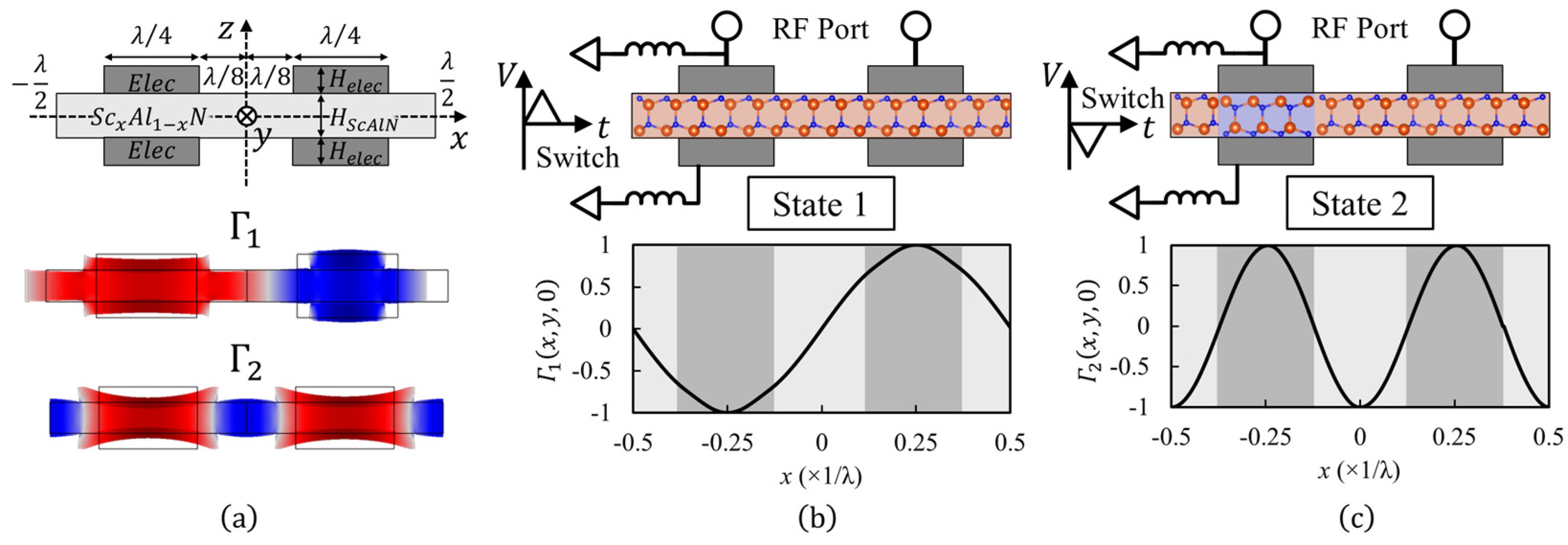
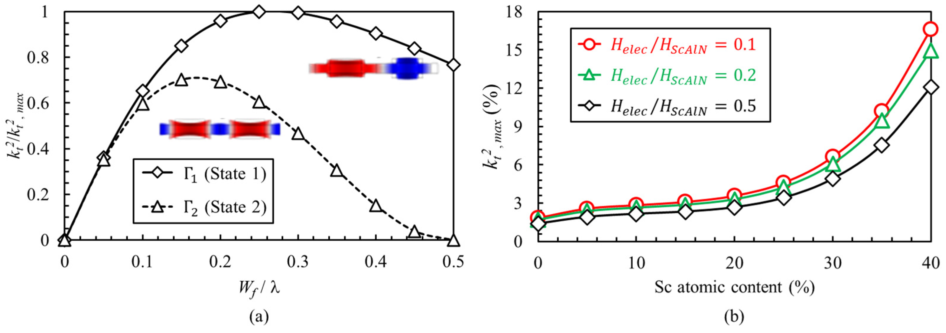
2. Concept
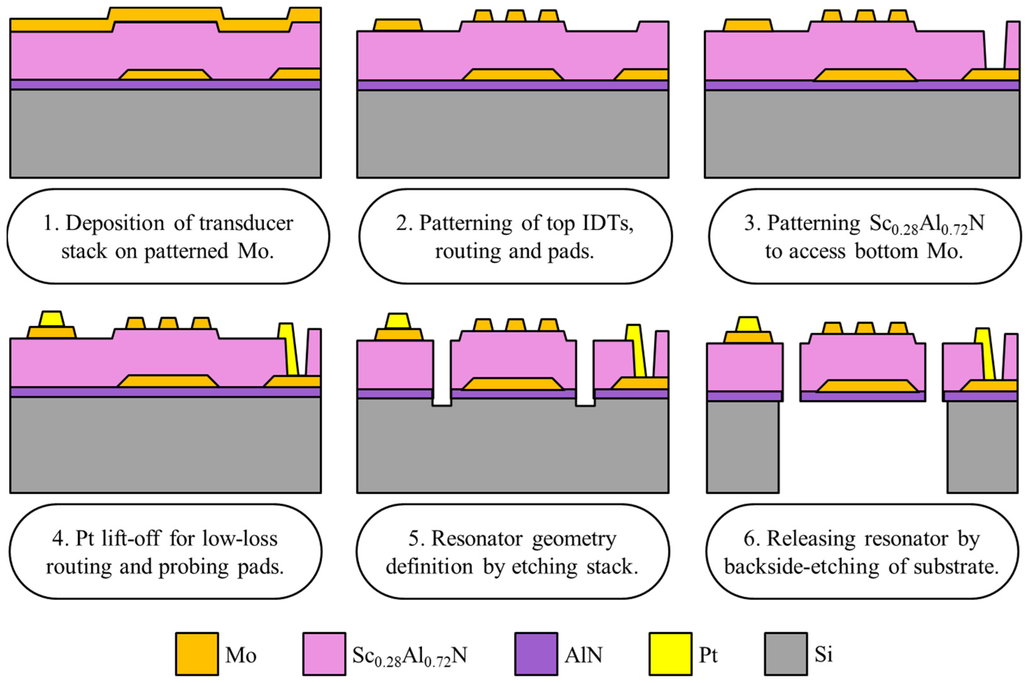
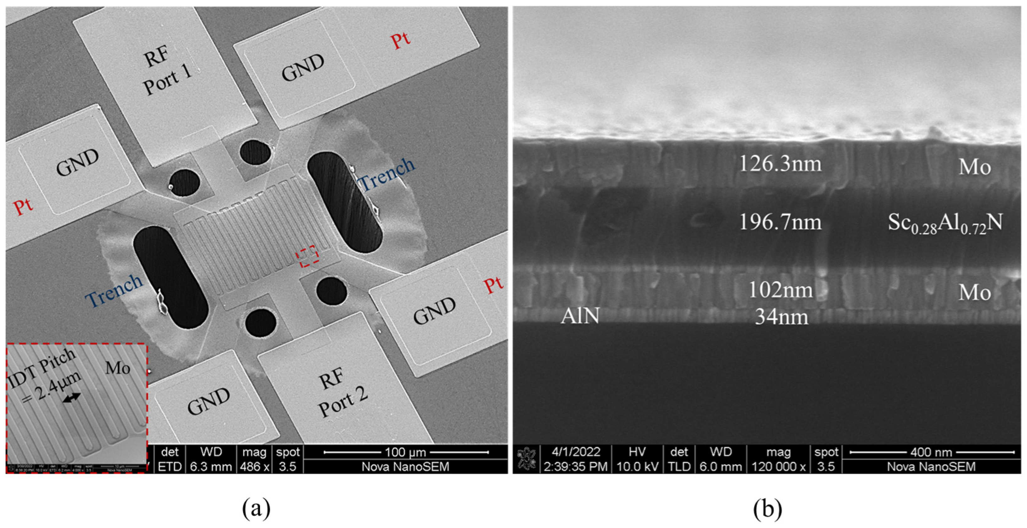
3. Fabrication Process
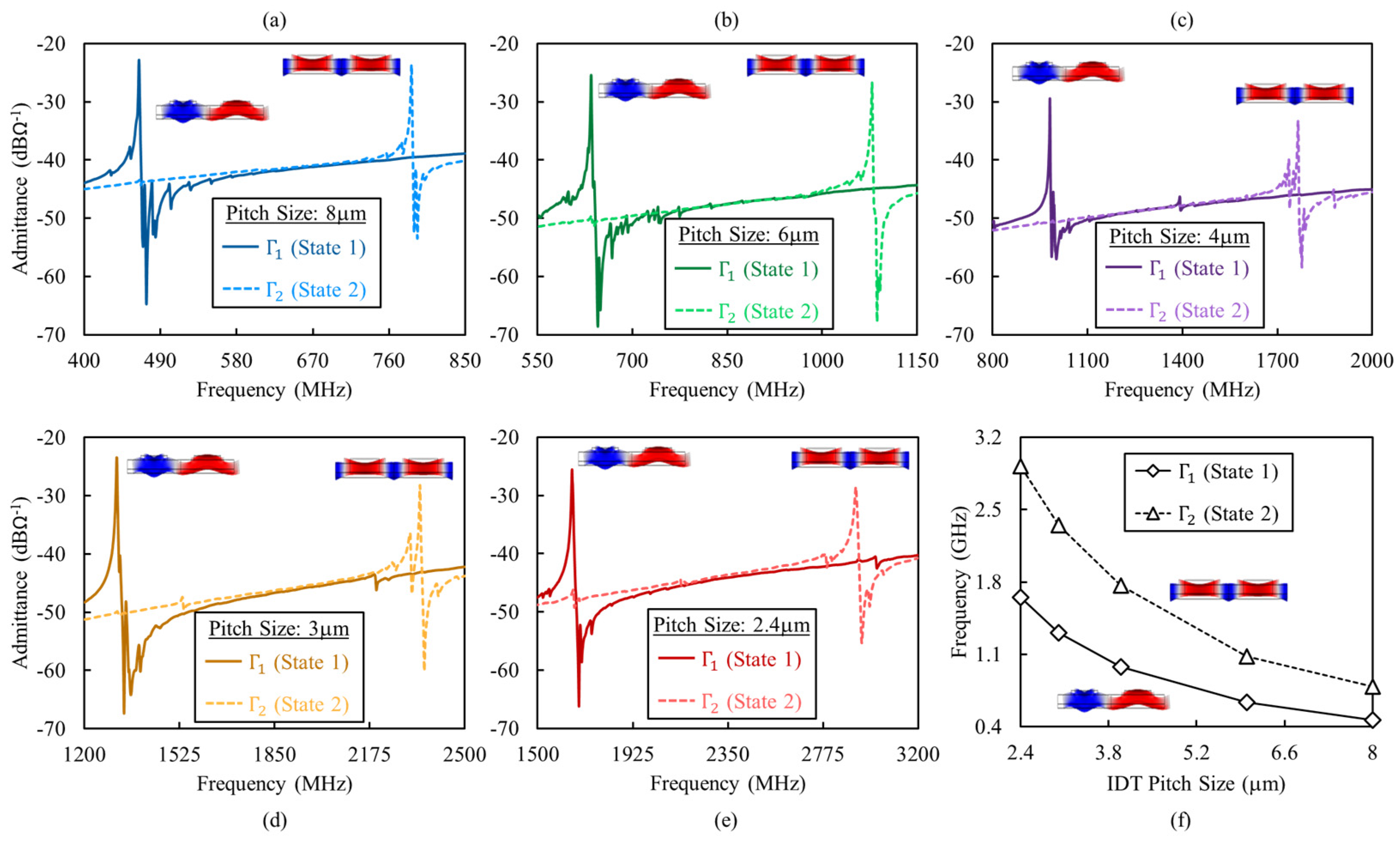
4. Characterization
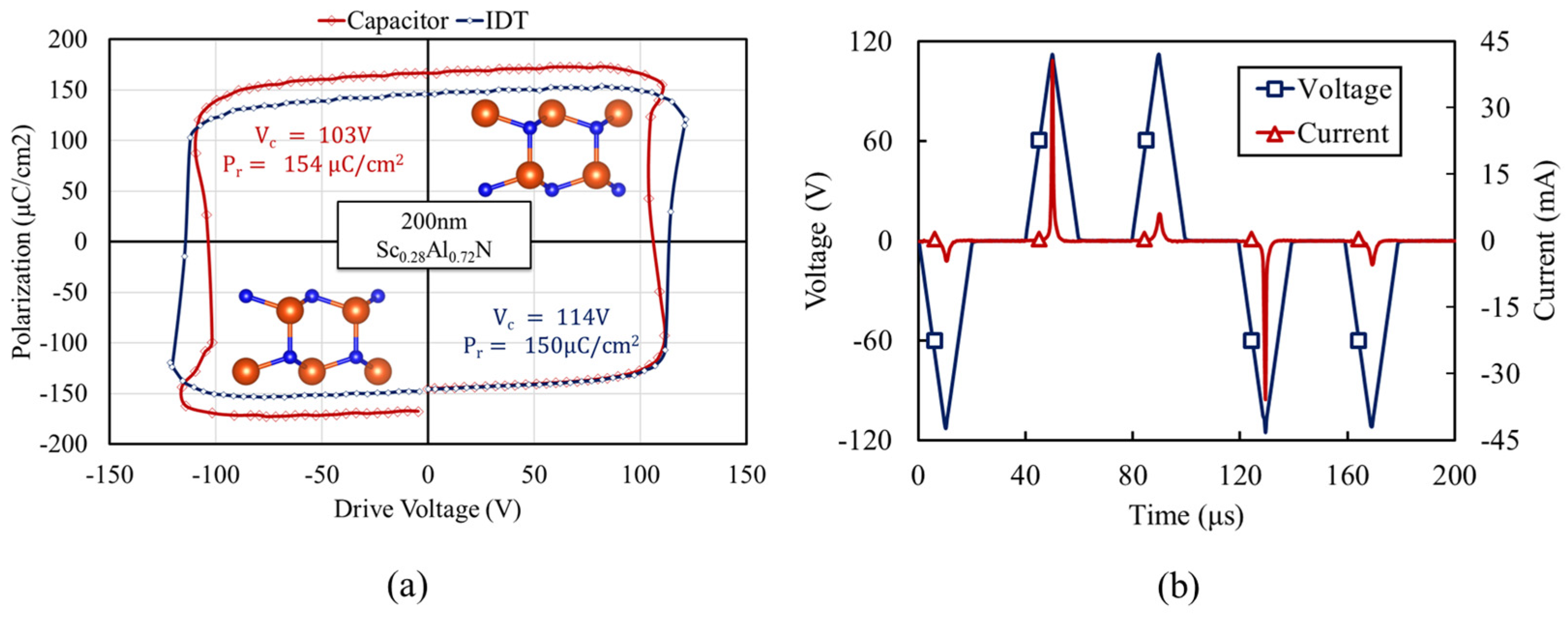
4.1. Ferroelectric Characterization
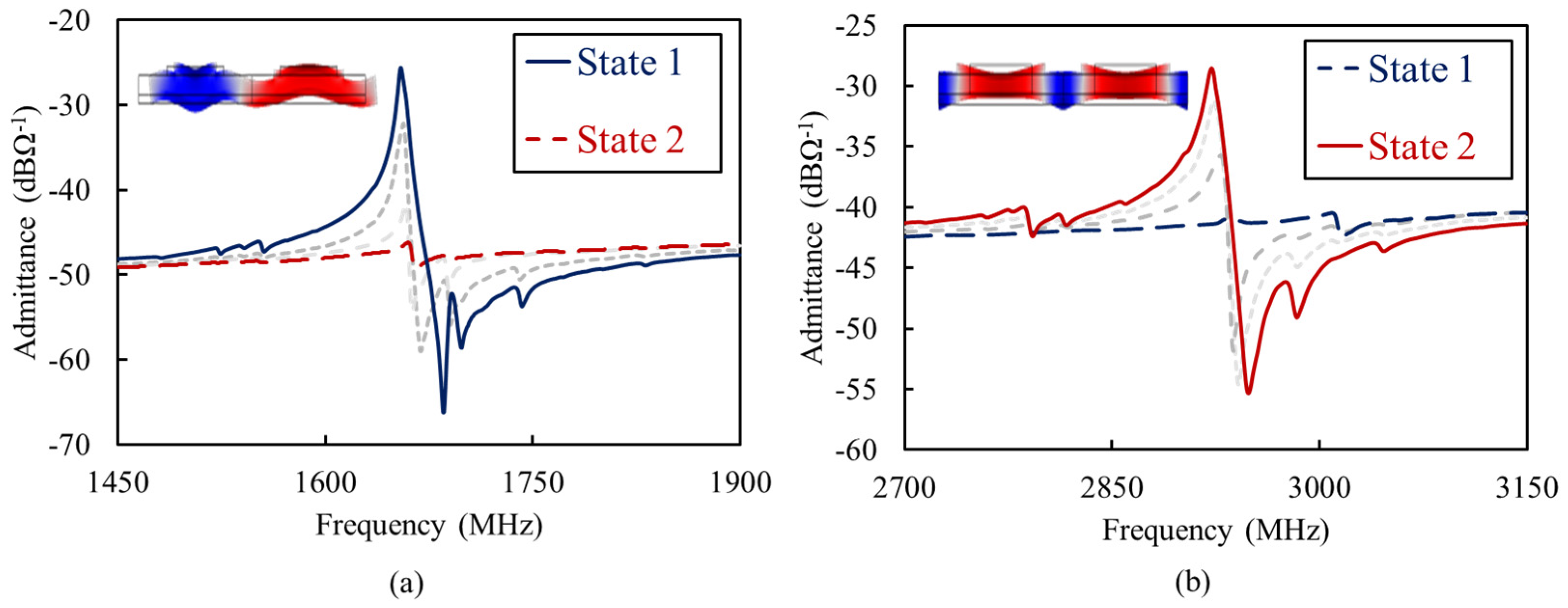
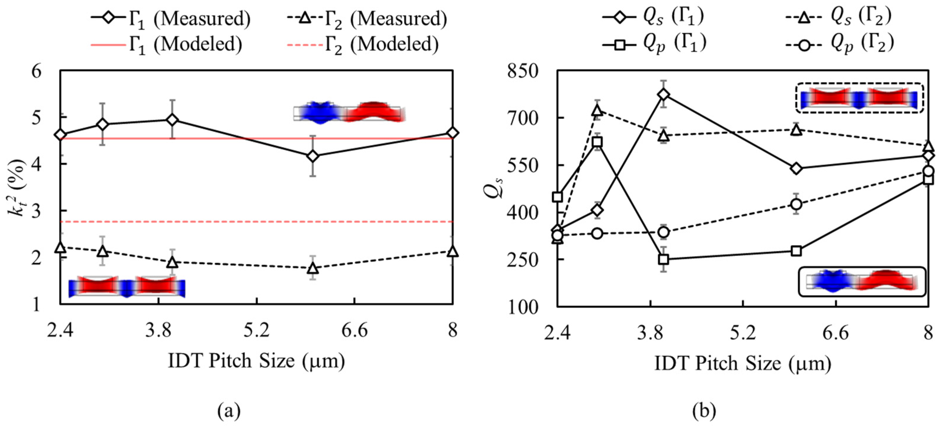
4.2. RF Characterization
5. Conclusions
Author Contributions
Funding
Data Availability Statement
Acknowledgments
Conflicts of Interest
References
- Akiyama, M.; Kamohara, T.; Kano, K.; Teshigahara, A.; Takeuchi, Y.; Kawahara, N. Enhancement of piezoelectric response in scandium aluminum nitride alloy thin films prepared by dual reactive cosputtering. Adv. Mater. 2009, 21, 593–596. [Google Scholar] [CrossRef] [PubMed]
- Shao, S.; Luo, Z.; Wu, T. High Figure-of-Merit Lamb Wave Resonators Based on Al0.7Sc0.3N Thin Film. IEEE Electron Device Lett. 2021, 4, 1378–1381. [Google Scholar] [CrossRef]
- Esteves, G.; Young, T.R.; Tang, Z.; Yen, S.; Bauer, T.M.; Henry, M.D.; Olsson, R.H., III. Al0.68Sc0.32N Lamb wave resonators with electromechanical coupling coefficients near 10.28%. Appl. Phys. Lett. 2021, 118, 71902. [Google Scholar] [CrossRef]
- Zhao, X.; Kaya, O.; Pirro, M.; Assylbekova, M.; Colombo, L.; Simeoni, P.; Cassella, C. A 5.3 GHz Al0.76Sc0.24N Two-Dimensional Resonant Rods Resonator with a Record kt2 of 23.9%. arXiv 2022, arXiv:2202.11284. [Google Scholar]
- Giribaldi, G.; Colombo, L.; Bersano, F.; Cassella, C.; Rinaldi, M. Investigation on the Impact of Scandium-doping on the kt2 of ScxAl1-xN Cross-sectional Lamé Mode Resonators. In Proceedings of the 2020 IEEE International Ultrasonics Symposium (IUS), Las Vegas, NV, USA, 7–11 September 2020. [Google Scholar]
- Fichtner, S.; Wolff, N.; Lofink, F.; Kienle, L.; Wagner, B. AlScN: A III-V semiconductor based ferroelectric. Appl. Phys. 2019, 125, 114103. [Google Scholar] [CrossRef]
- Wang, J.; Park, M.; Mertin, S.; Pensala, T.; Ayazi, F.; Ansari, A. A film bulk acoustic resonator based on ferroelectric aluminum scandium nitride films. J. Microelectromech. Syst. 2020, 29, 741–747. [Google Scholar] [CrossRef]
- Rassay, S.; Mo, D.; Li, C.; Choudhary, N.; Forgey, C.; Tabrizian, R. Intrinsically switchable ferroelectric scandium aluminum nitride lamb-mode resonators. IEEE Electron Device Lett. 2021, 42, 1065–1068. [Google Scholar] [CrossRef]
- Wang, J.; Zheng, Y.; Ansari, A. Ferroelectric Aluminum Scandium Nitride Thin Film Bulk Acoustic Resonators with Polarization-Dependent Operating States. Phys. Status Solidi (RRL) Rapid Res. Lett. 2021, 15, 2100034. [Google Scholar] [CrossRef]
- Rassay, S.; Hakim, F.; Ramezani, M.; Tabrizian, R. Acoustically Coupled Wideband RF Filters with Bandwidth Reconfigurablity Using Ferroelectric Aluminum Scandium Nitride Film. In Proceedings of the 2020 IEEE 33rd International Conference on Micro Electro Mechanical Systems (MEMS), Vancouver, BC, Canada, 18–22 April 2020. [Google Scholar]
- Dabas, S.; Mo, D.; Rassay, S.; Tabrizian, R. Intrinsically Tunable Laminated Ferroelectric Scandium Aluminum Nitride Extensional Resonator Based on Local Polarization Switching. In Proceedings of the 2022 IEEE 35th International Conference on Micro Electro Mechanical Systems Conference (MEMS), Tokyo, Japan, 9–13 February 2022. [Google Scholar]
- Mo, D.; Dabas, S.; Rassay, S.; Tabrizian, R. Complementary-Switchable Dual-Mode SHF Scandium-Aluminum Nitride BAW Resonator. arXiv 2022, arXiv:2205.03446. [Google Scholar]
- Ruby, R. A snapshot in time: The future in filters for cell phones. IEEE Microw. Mag. 2015, 16, 46–59. [Google Scholar] [CrossRef]
- Matthaiou, M.; Yurduseven, O.; Ngo, H.Q.; Morales-Jimenez, D.; Cotton, S.L.; Fusco, V.F. The road to 6G: Ten physical layer challenges for communications engineers. IEEE Commun. Mag. 2021, 59, 64–69. [Google Scholar] [CrossRef]
- Liu, Y.; Cai, Y.; Zhang, Y.; Tovstopyat, A.; Liu, S.; Sun, C. Materials, design, and characteristics of bulk acoustic wave resonator: A review. Micromachines 2020, 11, 630. [Google Scholar] [CrossRef] [PubMed]
- Vetury, R.; Hodge, M.D.; Shealy, J.B. High Power, Wideband Single Crystal XBAW Technology for sub-6 GHz Micro RF Filter Applications. In Proceedings of the 2018 IEEE International Ultrasonics Symposium (IUS), Kobe, Japan, 22–25 October 2018. [Google Scholar]
- Lin, C.; Yantchev, V.; Zou, J.; Chen, Y.; Pisano, A.P. Micromachined One-Port Aluminum Nitride Lamb Wave Resonators Utilizing the Lowest-Order Symmetric Mode. J. Microelectromech. Syst. 2014, 23, 78–91. [Google Scholar] [CrossRef]
- Mo, D.; Rassay, S.; Tabrizian, R. Intrinsically Switchable Ferroelectric Scandium Aluminum Nitride Bulk Acoustic Wave Resonators. In Proceedings of the 2021 21st International Conference on Solid-State Sensors, Actuators and Microsystems (Transducers), Orlando, FL, USA, 20–24 June 2021. [Google Scholar]
- Wang, R.; Bhave, S.A. Etch-A-Sketch filter. In Proceedings of the 2015 Transducers—2015 18th International Conference on Solid-State Sensors, Actuators and Microsystems (TRANSDUCERS), Anchorage, AK, USA, 21–25 June 2015. [Google Scholar]
- Lu, R.; Gong, S. A 15.8 GHz A6 Mode Resonator with Q of 720 in Complementarily Oriented Piezoelectric Lithium Niobate Thin Films. In Proceedings of the Joint Conference of the European Frequency and Time Forum and IEEE International Frequency Control Symposium (EFTF/IFCS), Virtual Conference, Gainesville, FL, USA, 7–17 July 2021. [Google Scholar]
- Ostrovskii, I.V.; Klymko, V.A.; Nadtochii, A.B. Plate wave stop-bands in periodically poled lithium niobate. JASA Expr. Lett. 2009, 125, EL129–EL133. [Google Scholar] [CrossRef] [PubMed] [Green Version]
- Rosenbaum, J.F. Bulk Acoustic Wave Theory and Devices; Artech House Acoustics Library: Boston, MA, USA; London, UK, 1988; pp. 125–163. [Google Scholar]
- Felmetsger, V.; Mikhov, M.; Ramezani, M.; Tabrizian, R. Sputter Process Optimization for Al0.7Sc0.3N Piezoelectric Films. In Proceedings of the 2019 IEEE International Ultrasonics Symposium (IUS), Glasgow, UK, 6–9 October 2019. [Google Scholar]
- Rassay, S.; Hakim, F.; Li, C.; Forgey, C.; Choudhary, N.; Tabrizian, R. A Segmented-Target Sputtering Process for Growth of Sub-50 nm Ferroelectric Scandium–Aluminum–Nitride Films with Composition and Stress Tuning. Phys. Status Solidi (RRL)–Rapid Res. Lett. 2021, 15, 2100087. [Google Scholar] [CrossRef]
- Lu, R.; Li, M.-H.; Yang, Y.; Gananoque, T.; Gong, S. Accurate Extraction of Large Electromechanical Coupling in Piezoelectric MEMS Resonators. J. Microelectromech. Syst. 2019, 28, 209–218. [Google Scholar] [CrossRef]
- Feld, D.A.; Parker, R.; Ruby, R.; Bradley, P.; Dong, S. After 60 years: A new formula for computing quality factor is warranted. In Proceedings of the 2008 IEEE Ultrasonics Symposium, Beijing, China, 2–5 November 2008. [Google Scholar]
- Zhang, H.; Liang, J.; Zhou, X.; Zhang, H.; Zhang, D.; Pang, W. Transverse Mode Spurious Resonance Suppression in Lamb Wave MEMS Resonators: Theory, Modeling, and Experiment. IEEE Trans. Electron Devices 2015, 62, 3034–3041. [Google Scholar] [CrossRef]
- Tabrizian, R.; Rais-Zadeh, M. The effect of charge redistribution on limiting the kt2.Q product of piezoelectrically transduced resonators. In Proceedings of the 2015 Transducers—2015 18th International Conference on Solid-State Sensors, Actuators and Microsystems (TRANSDUCERS), Anchorage, AK, USA, 21–25 June 2015. [Google Scholar]
- Segovia-Fernandez, J.; Piazza, G. Thermoelastic damping in the electrodes determines Q of AlN contour mode resonators. J. Microelectromech. Syst. 2017, 26, 550–558. [Google Scholar] [CrossRef]


Publisher’s Note: MDPI stays neutral with regard to jurisdictional claims in published maps and institutional affiliations. |
© 2022 by the authors. Licensee MDPI, Basel, Switzerland. This article is an open access article distributed under the terms and conditions of the Creative Commons Attribution (CC BY) license (https://creativecommons.org/licenses/by/4.0/).
Share and Cite
Rassay, S.; Mo, D.; Tabrizian, R. Dual-Mode Scandium-Aluminum Nitride Lamb-Wave Resonators Using Reconfigurable Periodic Poling. Micromachines 2022, 13, 1003. https://doi.org/10.3390/mi13071003
Rassay S, Mo D, Tabrizian R. Dual-Mode Scandium-Aluminum Nitride Lamb-Wave Resonators Using Reconfigurable Periodic Poling. Micromachines. 2022; 13(7):1003. https://doi.org/10.3390/mi13071003
Chicago/Turabian StyleRassay, Sushant, Dicheng Mo, and Roozbeh Tabrizian. 2022. "Dual-Mode Scandium-Aluminum Nitride Lamb-Wave Resonators Using Reconfigurable Periodic Poling" Micromachines 13, no. 7: 1003. https://doi.org/10.3390/mi13071003
APA StyleRassay, S., Mo, D., & Tabrizian, R. (2022). Dual-Mode Scandium-Aluminum Nitride Lamb-Wave Resonators Using Reconfigurable Periodic Poling. Micromachines, 13(7), 1003. https://doi.org/10.3390/mi13071003