Abstract
Recently, with the rapid development of data and information, it has become necessary to establish secure communications and appropriate security services to ensure a secure information exchange process. Therefore, to protect the privacy and confidentiality of private data, in this research, we use the Lorenz chaotic system to generate chaotic signals and apply them to the encryption of the communication of the Internet of Things (IoT) terminal sensor nodes. In addition, we design a simple proportional–integral–derivative (PID) controller and a quasi-sliding mode controller (QSMC) to synchronize the master-slave chaotic systems for decrypting the signals. Then, we encrypt the environmental signals measured from the IoT node at the transmitting side (master) and send them to the receiving side (slave). After the receiving side receives the encrypted signals, it decrypts them with the PID controller. Thus, the security of IoT information can be assured and realized.
1. Introduction
The term Internet of Things (IoT) originated in 1999, and was proposed by Kevin Aston of the MIT Auto-ID Center. With the current rapid development of technology, several methods are available for information transmissions, such as Wi-Fi, Bluetooth, and various Internet of Things communication protocols. However, with the advent of these methods, “information security” has become a crucial and inevitable concern. If important information is stolen by others, it is likely to cause irreparable impacts. Furthermore, there has been considerable focus and attention paid to the security of personal information, such as private biomedical information and home information. Thus, the secrecy of personal information must be ensured. Therefore, designing an effective information encryption system is an important goal that this study looks to achieve. Traditional encryption methods can be classified into symmetric encryption (e.g., data encryption standard, DES) and asymmetric encryption (e.g., RSA, ElGamal, and Paillier) [1,2,3]. The basic principle of symmetric encryption is to use Shannon’s concept of multiple encryptions, and apply confusion and diffusion for converting plain text into other formats and spreading every small part of the plain text to each part of the ciphertext to encrypt the information.
Many asymmetric encryption methods have been proposed, such as RSA, ElGamal, and Paillier encryption. These encryption methods mainly use mathematical computation and encrypt important information to avoid its decryption. However, the above algorithms can only be run under the integer domain. In this study, we use signals generated by two chaotic systems to encrypt the IoT signals/information and design a proportional–integral–derivative (PID) controller [4] and a quasi-sliding mode controller (QSMC) [5,6] to synchronize the systems and then recover the IoT signals/information.
In 1989, Ott et al. first proposed a method for controlling chaotic systems and named it the OGY method [7]. Subsequently, Pecora proposed the idea of synchronization control between two independent chaotic systems [8].
A chaotic system is a nonlinear dynamic system with complicated behaviors. Lorenz first used this system in an atmospheric simulation equation in 1963 [9]. However, it did not attract the attention of scientists until 1978. A chaotic system is extremely sensitive to initial conditions [10]. Butterfly effects can be generated by slight changes in the initial conditions, as well as by different attractors. There are various chaotic systems available, including the Hénon map [11], dynamic system in discrete time, Rössler attractor [12,13], and Lorenz oscillator, all of which are ternary nonlinear equations in continuous time.
Due to its complicated behaviors, the chaotic system has been employed in many domains, including communication, biology, mathematics, physics, and chemistry, as well as economics [14]. Thereafter, controlling/synchronizing chaotic systems and their applications became a research focus in the literature [15].
In this study, it is assumed that the collected IoT signals/information are very important signals, and therefore cannot be exposed to unsafe spaces. This study aims to encrypt, decrypt, and safely transmit the IoT signal/information. We use the chaotic system in the master-slave system, which requires a controller to synchronize the chaotic system.
2. Research Methods
2.1. Generalized Lorenz Chaotic System
The generalized Lorenz chaotic system generates ternary nonlinear equations in continuous time [16]:
where , c and d are real parameters. The Chen system (2) is a Lorenz-like system (1), with d = −c, c > 0, = c − a.
The system (2) takes as system parameters, and its dynamic equation can be obtained in continuous time, as shown in (3).
In this study, we present the main results for synchronization of chaotic systems (3). We use two chaotic systems: the transmitting side (master) with the state variables , and the receiving side (slave) , but with different initial conditions of and . Figure 1 and Figure 2 depict the responses of the chaotic system in the master chaotic system and the slave chaotic system in three dimensions with double-scroll attractors, respectively.
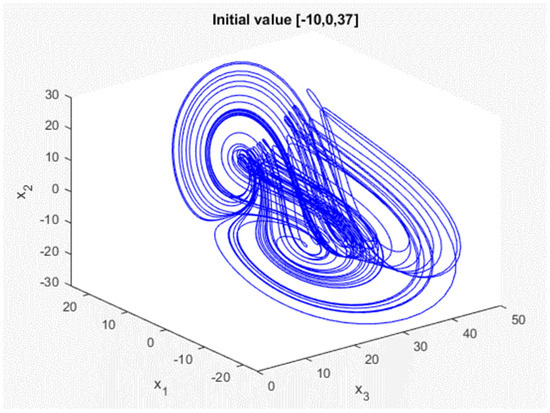
Figure 1.
Generalized Lorenz chaotic system response of master.
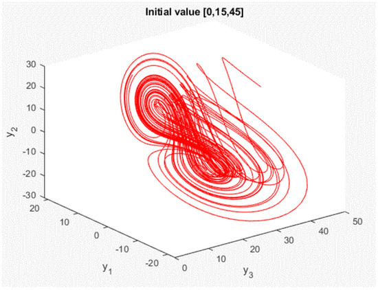
Figure 2.
Generalized Lorenz chaotic system response of slave.
2.2. PID Controller Synchronizing Generalized Lorenz Chaotic Systems
Because the IoT signal/information is not continuous, in order to encrypt the IoT signal/information later, we first discretize the system from continuous-time to discrete-time, with a sampling time (T) of 0.005 s via MATLAB software; the discrete time system can be obtained as follows (4), where k is the time index [17].
In the generalized Lorenz chaotic system, , , and states affect each other, and thus, we employ the PID controller in one of the states of the chaotic system for synchronization. In this study, we control the first states, and , of the systems. Figure 3 shows the states and of the master and slave before the application of the PID controller.
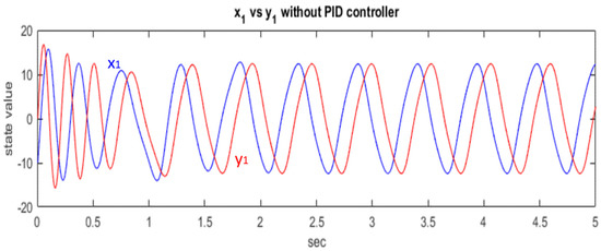
Figure 3.
Chaotic systems without PID controller.
Then, we add controller to the equations in discrete-time at the slave for synchronization, as shown in (4).
is the synchronization controller, including the proportional and differential controllers; shown in (5). The proportional controller (Kp) will consider the current error to speed up the time of the transient response so that the chaotic system, slave, will turn into a steady-state and synchronize with master as soon as possible. The integral controller (Ki) will make use of the summation of the past error to eliminate the steady-state’s error. Furthermore, once the proportional and integral controller over controls the system, the overshooting will occur. Here, we are going to use the differential controller (Kd). The differential controller will use the future error to predict the tendency of the system so that it can decrease the rise time and avoid overshooting.
After testing and adjusting various Kp, Ki, Kd values to synchronize two generalized Lorenz chaotic systems with different initial values, we choose the better Kp, Ki, Kd parameters for the subsequent implementation. Finally, we obtain Kp = 0.0025, Ki = 0, Kd = 0.65. To quickly synchronize the two chaotic systems, the Ki value is not used to reduce the occurrence of overshooting. Figure 4 shows the different initial values: and create different system responses. The blue line is the master system side and the red line is the slave system side.
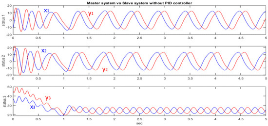
Figure 4.
Response to different initial values.
We use the tested PID controller, such as , in (6). Figure 5 shows the effect of the PID controller in synchronizing the two Generalized Lorenz chaotic systems. It can be seen from Figure 5 that the PID controller can quickly synchronize the chaotic system.
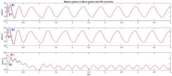
Figure 5.
PID controller synchronizing generalized Lorenz chaotic system.
2.3. Rössler Chaotic System
In the above, we used the PID controller to synchronize the generalized Lorenz chaotic system. However, this PID controller can only be applied to the master-slave chaotic system in the initial state of our design and . If the master and slave chaotic systems have different initial values, the synchronization effect of the above PID controller may not be effective; the chaotic system may not be able to achieve synchronization. Therefore, we want to design a chaotic system where the controller can be applied to any initial value. First, we introduce another chaotic system: the Rössler chaotic system. Its dynamic equation can be obtained in continuous time, as shown in (5), and the dynamic response, as shown in Figure 6, when the initial value is [5, 6, 14].
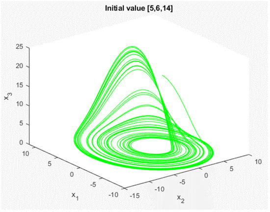
Figure 6.
Response of Rössler chaotic system.
2.4. Quasi-Sliding Mode Controller
First, we define the main system as and the slave system as y(t), so the error system is . Because the Rössler chaotic system has a nonlinear term in the third state, the controller is placed in the third state of the error system. The final error system is shown in (8).
In terms of the error system, we hope that the three error states can be as small as possible. We define here that the error system can converge to a very small value. This means that the systems on both sides of the master and servant will reach synchronization.
Next, we need to define a sliding surface. Let the system reach the sliding surface within a limited time, and then move along the sliding surface. In the theoretical description of the sliding mode, the system will be constrained on the sliding surface to reduce the order of the system and eliminate the nonlinear term. Since the nonlinear term is composed of state 1 and state 3, the sliding surface is defined as shown in (9).
The definition of dynamic error system means that and are entered in the sliding mode control. The solution of any error state of the error system must satisfy and . Therefore, when the error system enters the sliding mode, and . Because the error system needs to converge to close to zero for the system to reach synchronization, the value of is very small. With this equation , the dynamic equation of the error system can be rewritten as shown in (10).
After the sliding surface is introduced, the error system is reduced to a second-order system. If we ignore the small value of , it can be expressed as . Now, we just ignore and consider the response of this second-order system. The second-order system can be simplified as shown in (11).
According to the control theory [18], we can know that the transfer function of the pole is . Then, we use Routh-Hurwitz stability [19,20] to find the range of , as in (12). Finally, we find .
So far, we have proved that must be very small and the range of makes state 1 and state 2 of the error system stable. Now, it is necessary to prove that state 3 of the error system can also be stable; to prove that the sliding surface should converge and find the form of the controller. The controller form u(t) is shown in (13), and the Lyapunov function [21,22] has been used to prove (14); that the sliding surface will converge.
Therefore, has been selected from the controller, which means , when . This means that will converge to the region of . Then, we conduct a simple simulation: let , , , and . The initial value and . The system response is shown in Figure 7.
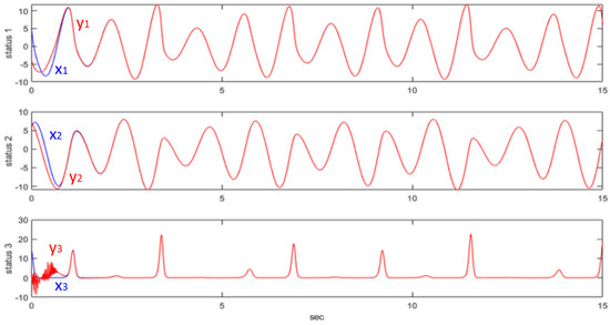
Figure 7.
QSM controller synchronizing the Rössler chaotic system.
3. Information Security
3.1. Chaotic System Encryption Architecture for the Information Security
In this study, we use the PID controller to synchronize the master-slave chaotic systems, which uses the error to adjust the controller and synchronize the system. Thus, one of the states of the chaotic system must be simultaneously transmitted with the encrypted data. The architecture of the secure IoT system is shown in Figure 8.
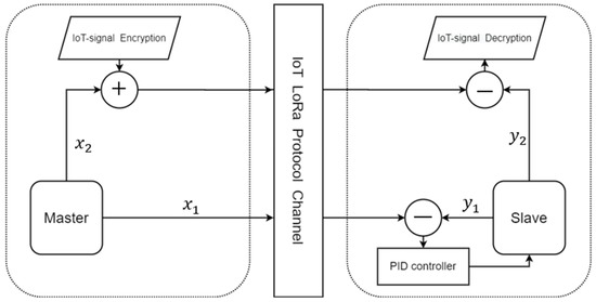
Figure 8.
The secure IoT signal system architecture (PID).
In the transmitter side (master system), is used in the encryption algorithm via the chaotic masking method, and is used for the chaos synchronization by the PID controller design; thus, is sent to the slave. When the chaotic system reaches synchronization, we take to decrypt the IoT signal. In the middle of the communication system, we use the LoRa module.
3.2. Information Security
As can be seen from Figure 8, we use of the chaotic system to encrypt the IoT signal. The encryption method is shown in (15).
Because the chaotic system has good pseudo-random characteristics, unpredictability of the orbit, sensitivity to the initial state, and control parameters, etc., if a thief steals the encrypted value, they cannot crack it. Even if the thief steals of the chaotic system and simulates the response of the transmitting side system, because the chaotic system has a butterfly effect, it is impossible to find . As long as the system state is worse, the response will be completely different. Finally, the receiving side (slave system) has synchronized the chaotic system . Therefore, the receiving side can use to restore the IoT signal. The decryption method is shown in (16).
3.3. Simulation of Information Security
Before entering the implementation, we conduct a simulation of information security to test whether this architecture can use a chaotic system to encrypt and decrypt signals. First, we use a random number generator to generate a random signal, as shown in Figure 9.
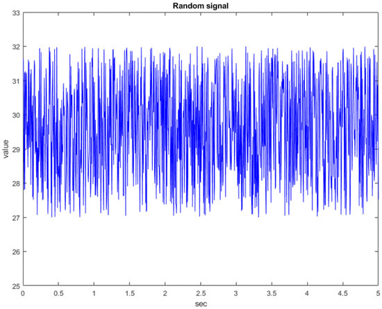
Figure 9.
The random signal graph.
Next, the random signal is encrypted with the state of the chaotic system, as shown in Figure 10. The blue line is the original random signal and the black line is the encrypted signal. As we can see from Figure 10, the original signal has been completely encrypted. The original random signal cannot be solved from the encrypted signal. Finally, the chaotic system at the receiving side is used for decryption, as shown in Figure 11. As can be seen from Figure 11, the decryption fails before 0.5 s because the chaotic systems at both sides have not reached synchronization. After 0.5 s, the chaotic systems at both sides reach synchronization, so the decryption is successful. Therefore, the simulation proves that this architecture is feasible.
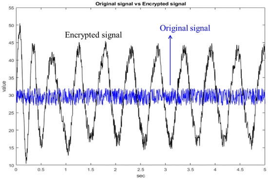
Figure 10.
Comparison chart of original signal and encrypted signal.
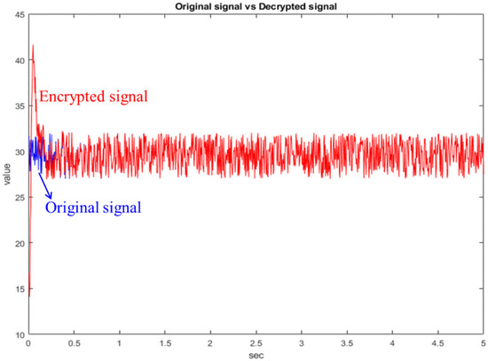
Figure 11.
Comparison chart of original signal and decrypted signal.
3.4. QSMC Synchronized Chaotic System Encryption Architecture for the Information Security
Above, we outlined the encryption architecture using the PID controller. In the same way, we can fit it into the form of QSMC. First, the QSMC can be simplified into a form such as (17). Transmit and to the receiving end to realize the sliding mode controller. It is safer than the PID controller, because the value transmitted by the QSMC is a linear combination of the master state and it is not easy to guess the state of the system, and the PID controller has exposed one of the system states. Figure 12 shows the encryption architecture of QSMC.
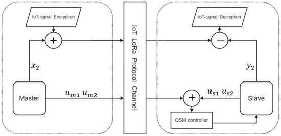
Figure 12.
The secure IoT signal system architecture (QSM).
4. Implement
4.1. IoT Signal/Information
In this study, we used the DHT-22 sensor as an example of IoT signal/information, as shown in Figure 13. The DHT-22 sensor is a temperature and humidity composite sensor with a calibrated digital signal output. It uses dedicated digital module acquisition technology, as well as temperature and humidity sensing technology to ensure that the product has extremely high reliability and excellent long-term stability. Therefore, the product has the advantages of excellent quality, ultra-fast response, strong anti-interference ability, and high-cost performance. The temperature and humidity information are the most common signals in the IoT. We used DHT-22 with a sampling time of 0.005 s, as shown in Figure 14.
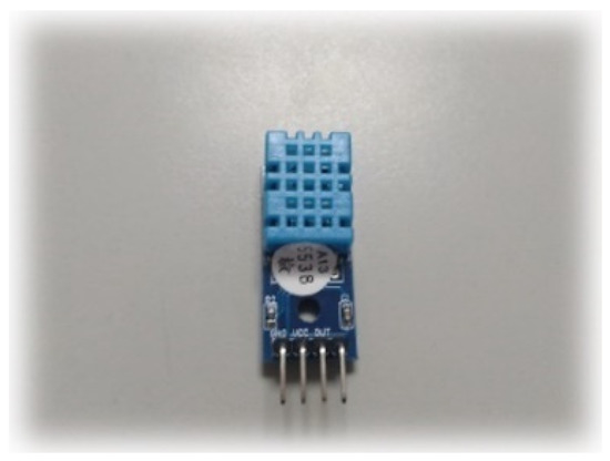
Figure 13.
Temperature sensor DHT-22.
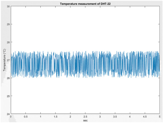
Figure 14.
Temperature measured by DHT-22.
4.2. IoT Communication Channel
In order to allow temperature sensing data to be transmitted in the IoT. We used the SX LoRa-1278 communication module, as shown in Figure 15. In terms of IoT communication technology, one of the LoRa (Long Range) low-power wide-area network communication technologies was an ultra-long-distance wireless transmission scheme based on spread spectrum technology, adopted and promoted by Semtech. LoRa uses a high spreading factor to obtain a higher signal gain. Compared with the general FSK, the signal-to-noise ratio requires 8 dB, while LoRa only requires −20 dB. This provides users with a simple system that can achieve long-distance, low power consumption, and large capacity, and can then expand the sensor network. Therefore, using the many advantages of LoRa, the nodes of each LoRa module were deployed in the space to collect the required data, such as temperature, humidity, distance, etc. However, because all LoRa frequency bands are publicly shared and free, we needed an encryption system to protect the security of these data.
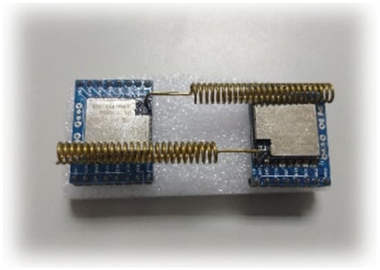
Figure 15.
SX LoRa-1278 communication module.
To ensure the correct rate of the LoRa communication module, we conducted delay time and different distance tests to find a suitable delay time for our indoor applications. We designed an experiment in which the transmitting side transmitted a thousand pieces of data, and the data was generated by the temperature and humidity sensing module, testing the reception rate of the receiving side. Table 1 shows the experimental results. Figure 16 shows the experimental environment. From Table 1, it can be seen that the reception rate of the LoRa module was better at close range, but it was found that the reception rate of the LoRa module was greatly affected when the distance was increased. Therefore, the indoor application of the LoRa module to sense, transmit, and receive various indoor data distances is an important consideration. Finally, we chose a delay time of 200 milliseconds at a receiving rate of 10 m, which was the transmission interval of the LoRa module.

Table 1.
SX LoRa-1278 reception rate experiment results.
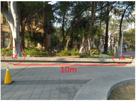
Figure 16.
SX LoRa-1278 communication experimental environment.
4.3. Implementation of the Chaotic Encryption System in IoT Information Security
First, we used Arduino to connect the DHT-22 to detect temperature values from the environment. The chaotic signal generated by Arduino encrypts the temperature value and then it is transmitted to the receiving side by SX LoRa-1278. The receiving side uses the PID controller to synchronize the chaotic system and then performs decryption. Finally, the temperature value detected by the original DHT-22 is decrypted. The IoT information security system architecture is shown in Figure 17. The results of integrating the LoRa and the chaos system in the ARDUINO interface are shown in Figure 18. As can be seen from Figure 18, the chaotic system reached synchronization when the temperature decryption was successful. The same was true for the encryption and decryption architecture of QSMC.
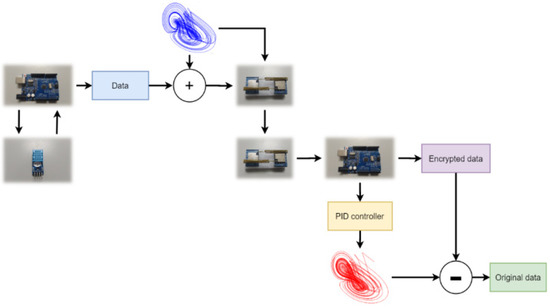
Figure 17.
Chaotic system encryption IoT signal architecture diagram.
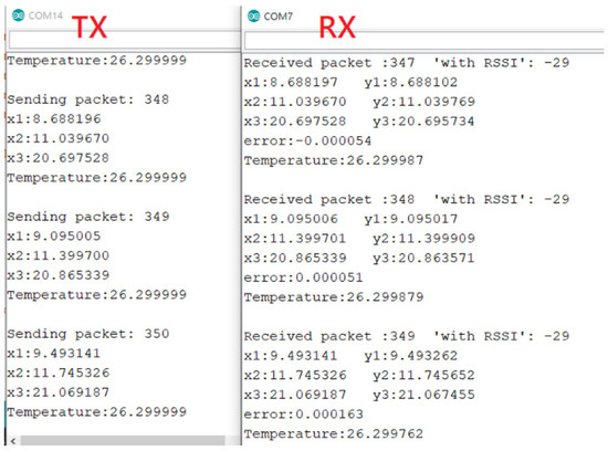
Figure 18.
The result of implementing a chaotic encryption system.
5. Conclusions
The results obtained in this study verify the fact that the characteristics of IoT signals/information after encryption and decryption remain the same, which means that the two chaotic systems are synchronized and generate the same states so that the IoT information remains correct.
We used SX LoRa-1278 to communicate between the two chaotic systems and synchronize them with the proportional–derivative controller or the quasi-sliding mode controller. The experimental results indicate that the master chaotic system successfully transmits the encrypted IoT signals/information to the other side by using the slave chaotic system. Moreover, we obtained the same IoT signals/information after decryption.
Thus, we achieved our goal based on the chaotic system, with a synchronization controller applied to the security of the IoT information.
Funding
This work was financially supported by the National Science and Technology Council, Taiwan, under grant 111-2218-E-006-009-MBK and 111-2218-E-006-018.
Data Availability Statement
Data are contained within the article.
Acknowledgments
I would also like to extend my thanks to the members of the Intelligent Control Laboratory of the Department of Engineering Science, National Cheng Kung University for their help.
Conflicts of Interest
The author declares no conflict of interest.
References
- Somani, U.; Lakhani, K.; Mundra, M. Implementing digital signature with RSA encryption algorithm to enhance the Data Security of cloud in Cloud Computing. In Proceedings of the 2010 First International Conference On Parallel, Distributed and Grid Computing (PDGC 2010), Solan, India, 28–30 October 2010; pp. 211–216. [Google Scholar] [CrossRef]
- ElGamal, T. A public key cryptosystem and a signature scheme based on discrete logarithms. IEEE Trans. Inf. 1985, IT-31, 469–472. [Google Scholar] [CrossRef]
- Paillier, P. Public-key cryptosystems based on composite degree residuosity classes. In Proceedings of the International Conference on the Theory and Application of Cryptographic Techniques, Prague, Czech Republic, 1 January 1999; pp. 223–238. [Google Scholar]
- Mughees, A.; Mohsin, S.A. Design and Control of Magnetic Levitation System by Optimizing Fractional Order PID Controller Using Ant Colony Optimization Algorithm. IEEE Access 2020, 8, 116704–116723. [Google Scholar] [CrossRef]
- Utkin, V.; Poznyak, A.; Orlov, Y.; Polyakov, A. Conventional and high order sliding mode control. J. Frankl. Inst. 2020, 357, 10244–10261. [Google Scholar] [CrossRef]
- Wang, J.; Yang, C.; Shen, H.; Cao, J.; Rutkowski, L. Sliding-Mode Control for Slow-Sampling Singularly Perturbed Systems Subject to Markov Jump Parameters. IEEE Trans. Syst. Man Cybern. Syst. 2020, 51, 7579–7586. [Google Scholar] [CrossRef]
- Ott, E.; Grebogi, C.; Yorke, J.A. Theory of 1st order phase-transitions for chaotic attractors of nonlinear dynamical-systems. Phys. Lett. A 1989, 135, 343–348. [Google Scholar] [CrossRef]
- Pecora, L.M.; Carroll, T.L. Synchronization in chaotic systems. Phys. Rev. Lett. 1990, 64, 821–824. [Google Scholar] [CrossRef] [PubMed]
- Lorenz, E.N. Deterministic non-periodic flows. J. Atmos. Sci. 1963, 20, 130–141. [Google Scholar] [CrossRef]
- Azar, A.T.; Vaidyanathan, S. Advances in Chaos Theory and Intelligent Control; Springer International Publishing AG: Chem, Switzerland, 2016. [Google Scholar]
- Wu, J.H.; Liao, X.F.; Yang, B. Image encryption using 2D Hénon-Sine map and DNA approach. Signal Process. 2018, 153, 11–23. [Google Scholar] [CrossRef]
- Rössler, O. An equation for continuous chaos. Phys. Lett. A 1976, 57, 397–398. [Google Scholar] [CrossRef]
- Rössler, O.E. Continuous chaos–four prototype equations, Bifurcation Theory and Applications in Scientific Disciplines. Ann. N. Y. Acad. Sci. 1979, 316, 376–392. [Google Scholar] [CrossRef]
- Jaeger, H.; Haas, H. Harnessing Nonlinearity: Predicting Chaotic Systems and Saving Energy in Wireless Communication. Science 2004, 304, 78–80. [Google Scholar] [CrossRef] [PubMed]
- Liao, T.-L.; Tsai, S.-H. Adaptive synchronization of chaotic systems and its application to secure communications. Chaos Solitons Fractals 2000, 11, 1387–1396. [Google Scholar] [CrossRef]
- Leonov, G.A.; Kuznetsov, N.V. On differences and similarities in the analysis of Lorenz, Chen, and Lu systems. Appl. Math. Comput. 2015, 256, 334–343. [Google Scholar] [CrossRef]
- Liao, T.-L.; Chen, C.-Y.; Chen, H.-C.; Chen, Y.-Y.; Hou, Y.-Y. Realization of a Secure Visible Light Communication System via Chaos Synchronization. Math. Probl. Eng. 2021, 2021, 5073562. [Google Scholar] [CrossRef]
- Glad, T.; Ljung, L. Control Theory; CRC Press: Boca Raton, FL, USA, 2000. [Google Scholar]
- DeJesus, E.X.; Kaufman, C. Routh-Hurwitz criterion in the examination of eigenvalues of a system of nonlinear ordinary differential equations. Phys. Rev. A 1987, 35, 5288–5290. [Google Scholar] [CrossRef] [PubMed]
- Ahmed, E.; El-Sayed, A.M.A.; El-Saka, H.A.A. On some Routh–Hurwitz conditions for fractional order differential equations and their applications in Lorenz, Rössler, Chua and Chen systems. Phys. Lett. A 2006, 358, 1–4. [Google Scholar] [CrossRef]
- Chang, Y.C.; Nima, R.; Gao, S. Neural lyapunov control. arXiv 2020, arXiv:2005.00611. [Google Scholar]
- Liu, L.; Liu, Y.-J.; Chen, A.; Tong, S.; Chen, C.L.P. Integral Barrier Lyapunov function-based adaptive control for switched nonlinear systems. Sci. China Inf. Sci. 2020, 63, 132203. [Google Scholar] [CrossRef]
Publisher’s Note: MDPI stays neutral with regard to jurisdictional claims in published maps and institutional affiliations. |
© 2022 by the author. Licensee MDPI, Basel, Switzerland. This article is an open access article distributed under the terms and conditions of the Creative Commons Attribution (CC BY) license (https://creativecommons.org/licenses/by/4.0/).