1. Introduction
Mechanical equipment manufacturing is critical for the manufacturing industry. As the precision requirements of mechanical systems in modern industry improve continually, the machining precision and motion precision requirements of equipment manufacturing of mechanical systems increase [
1,
2]. At present, precision and ultra-precision processing technologies are important methods for the realization of mechanical equipment precision manufacturing [
3,
4,
5,
6,
7]. Precision feed technology is a vital method for the realization of ultra-precision processing technology [
8,
9,
10]. Thus far, the macro/micro dual-drive system has resolved the contradiction between large motion travel and high motion precision, being able to provide motion with large travel and high precision, and the macro/micro dual-drive system has been used widely in high-technology fields such as the advanced war industry, biological medicine, and precision electronics [
11,
12,
13,
14,
15,
16]. In the macro/micro dual-drive system, the micro-drive system can compensate for the motion error of the macro-drive system and provide high-precision motion for the macro/micro dual-drive system [
17,
18,
19,
20].
In recent years, many scholars have mainly focused on mechanical structure design, structure optimization, dynamic analysis, and practical application of the micro-drive system. A precision MEMS (micro-electromechanical systems) mechanism with six degrees of freedom has been designed, and the mechanism can be applied to electron transport microscopes; in addition, the mechanism has realized precision rotary motion in three-dimensional space [
21]. A micro bridge mechanism with three degrees of freedom has been developed, and the Z-direction of the mechanism has high stiffness and stability, meaning that it can resist a sizeable external thrust, and the structure optimization of the mechanism is completed by the sequential quadratic rule; the experimental results show that the optimization method is very effective [
22]. A flexible micro mechanism with two-direction rotary motion driven by a giant magnetostrictive actuator has been proposed. The dynamic model of the mechanical parameters is given based on dynamic model establishment [
23]. Xue et al. designed a new chip-level comb-drive magnified micro-drive platform with 3-DOF (degrees of freedom), and the maximum displacements of the platform in three directions were 25.2 μm × 20.4 μm × 58.5 μm [
24]. Liu et al. presented a new compliant mechanism constituted by flexure hinges with two straight-circular and multi-notched components; the structural optimization of the mechanism was completed using a topological method, and the mechanisms’ performance was analyzed by finite element methods such as stiffness, rotary precision, and horizontal stress, with the results showing excellent mechanism performance [
25].
At present, micro-drive systems research is concentrated mainly on linear motion, and a large amount of research has been used in production [
26,
27]. However, compared with linear systems, the research on micro-drive rotary systems is scarce and dated [
28]. In addition, the positional accuracy of linear motion can reach the nanometer level [
29,
30], but the rotary motion is only at the arc-second (″) level [
31,
32,
33,
34].
The positional accuracy being restricted to the sub-arc-second level means that the maximum position error of the rotary motion system is limited to the scope of the 0.1 arc-second level. The rotary motion at the sub-arc-second level has essential applications in micromachining fields such as ultra-precision machining, chip processing, and ultra-precision medical instruments. The micro-drive rotary system provides a way to realize sub-arc-second positioning; therefore, a micro-drive rotary system with sub-arc-second positional accuracy has important value in the above micromachining fields. Thus, it is important to study the positioning performance of a sub-arc-second micro-drive rotary system, and this study can promote the development of ultra-precision micromachining technology.
As the positional accuracy of rotary motion is lower than linear motion and can only reach the level of arc-second, this paper presents research on the positioning performance of a sub-arc-second micro-drive rotary system, and this study can promote the development of micro-machining technology with ultra-precision (sub-arc-second) requirements. In this paper, a sub-arc-second micro-drive rotary system was developed to accurately transform linear motion with ultrahigh precision into rotary motion. The positioning performance of the system was analyzed based on the research on drive performance and transformation performance. The simulation and experimental results indicate that its motion accuracy can reach the sub-arc-second level, and the positioning performance was good.
The rest of this paper is organized as follows.
Section 2 introduces the micro-drive rotary system. The drive performance analysis of the system by experiments is described in
Section 3. In
Section 4, three methods are used to analyze the performance of the system. In
Section 5, the results of the positioning performance analysis are presented. The conclusions are presented in
Section 6.
2. Micro-Drive Rotary System
At present, the positional accuracy of linear motion can reach the nanometer level, and the positional accuracy of a few micro-actuators can even reach the sub-nanometer level. However, the positional accuracy of rotary motion is only at the arc-second (″) level. In this paper, a micro-drive rotary system was designed to provide rotary motion at the sub-arc-second level. In this system, a new micro rotary mechanism can transform the linear motion into rotary motion with high precision, and the linear motion is driven by PZT with resolution at the sub-nanometer level.
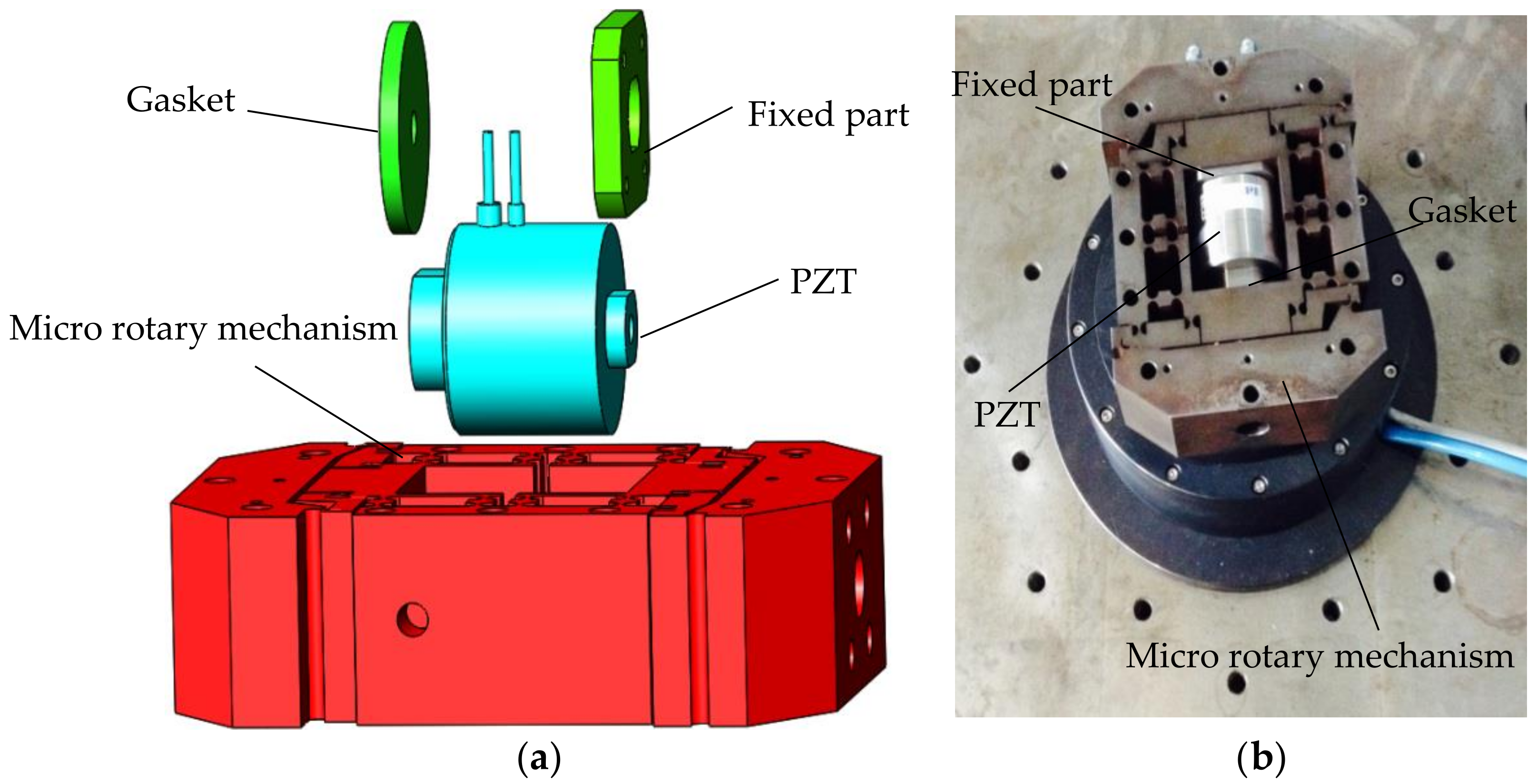
The micro-drive rotary system is developed as shown in
Figure 1: the fixed part and the gasket are designed to connect the two ends of the PZT to the micro rotary mechanism.
The motion of the micro-drive rotary system consists of the drive motion and the transformation motion. The drive motion of the micro rotary mechanism has a linear motion displacement ∆v, which is driven by the PZT, with driven voltage U. The transformation motion of the system has a rotary motion displacement ∆θ, which is transformed by the micro rotary mechanism with the linear motion displacement ∆v. Therefore, to analyze the positioning performance (i.e., the functional relationship between U and ∆θ) of the micro-drive rotary system, drive performance (i.e., the functional relationship between U and ∆v) and transformation performance (i.e., the functional relationship between ∆v and ∆θ) analyses are necessary.
2.1. Micro-Actuators
The two types of standard micro-actuators are PZT (piezoelectric ceramic actuator) and GMA (giant magnetostrictive actuator), and the motion precision of the PZT is higher than that of the GMA. PZT is a type of micro driver that functions according to the inverse piezoelectric effect of piezoelectric materials. PZTs can precisely drive the micro mechanism in the sub-10 micrometer range. Due to its advantages such as high precision, rapid response, small size, and large output force, PZTs have been used widely in the advanced war industry, biological medicine, precision electronics, intelligent robotics, and precision machinery. According to the parameter demands of this system such as the size of the driver, driving force, and driving displacement, the high-precision PZT of the P-235.1S model, produced by the PI Company, was selected. The PZT is shown in
Figure 2. The main parameters of the PZT are shown in
Table 1. Closed-loop travel was 0–15 μm, and the closed-loop resolution was 0.3 nm.
2.2. Micro Rotary Mechanism
When flexible material is stressed, the flexure hinge will produce minor deformation, which can realize the transmission motion and guiding motion according to the compound motion principle of the flexure hinge. In this paper, a micro rotary mechanism was designed based on the compound motion principle of the flexure hinge. The working principle of the micro rotary mechanism is shown in
Figure 3. The micro rotary mechanism includes four parts: parts a, b, c, and d.
The structure and working principle of the micro rotary mechanism are shown in
Figure 3. There are 26 flexure hinge elements in the x–y plane, with symmetrical distribution about center point 0, and the 26 flexure hinge elements are of the same size and are numbered, as shown in
Figure 3. As the mechanism has a symmetrical structure when in motion, it is feasible only to study the parts in the top half of the mechanism (i.e., the above -x-axle parts of the mechanism) when analyzing its working condition. Due to the symmetrical structure, a parts contain a
1 and a
2, b parts contain b
1 and b
2, d parts contain d
1 and d
2, and part c is made up of 26 flexure hinges (1–26). The pivots of flexure hinges 2, 6, 8, 11, and 13 are connected with parts, and the a
1 and a
2 parts are fixed with 3 M4 socket head cap screws (the six screws are simplified for simple construction). The pivots of flexure hinges 3 and 5 are connected with d
1 parts, and the d
1 and d
2 parts are connected with the rotary workbench with 3 M4 socket head cap screws (the six screws are simplified for simple construction). The pivots of flexure hinges 1, 4, 7, 9, 10, and 12 are connected with b
1 parts. The connecting rod 123 (the connecting rod consists of points 1, 2, and 3, and the other connecting rods are defined in the same manner) completes the transformation of linear motion into rotary motion. The flexure hinges 6, 7, 8, 9, 10, 11, 12, and 13 complete the guidance for the mechanism, and the mechanism will have no non-motion direction (the
y-axis is the motion direction) displacement. The flexure hinges 4 and 5 are used to balance the x-direction force and moment because the flexure hinge 1 moves around the pivot of flexure hinge 2 while the mechanism is working.
The mechanism is processed by wire-electrode cutting with spring steel 60Si2Mn material, which is shown in
Figure 3b.
2.3. The Positioning Motion of the System
The positioning motion of the micro-drive rotary system consists of the drive motion and the transformation motion. Therefore, in order to realize high-precision rotary motion, it is essential to study the process of the two motions.
2.3.1. The Drive Motion Process
The drive motion occurs when the system obtains a linear motion displacement Δv, which is driven by the PZT with driven voltage U (i.e., the drive process from U to Δv).
Piezoelectric ceramics are composed of large amounts of small crystal particles. The atoms of each small crystal particle are arrayed with a certain regularity, but the crystal lattices of each small crystal particle are arrayed in random order. As a result, the crystal particles of piezoelectric ceramics are arrayed in chaotic and random order, and the crystals with the above structure are known as polycrystalline structures. The distance between positive and negative charges inside piezoelectric ceramics will increase when increasing electric field intensity is applied to them. The electric field is in the same direction as the crystals’ polarization. Additionally, the length of the piezoelectric ceramics will enlarge along the direction of the crystals’ polarization. The process of transforming electrical energy into mechanical energy is known as the inverse piezoelectric effect.
When the electric field intensity of the inside of the PZT increases, the number of electric domains with the same direction as the electric field will decrease, and the distance among charges of piezoelectric ceramics will increase; then, the length of the piezoelectric ceramics will increase, and an elongation drive displacement of PZT is exported. In contrast, when the electric field intensity of the inside of the PZT decreases, then the length of the piezoelectric ceramics will shrink; therefore, a shortened drive displacement of PZT is exported.
Due to the material attributes of piezoelectric ceramics, PZTs have several disadvantages such as creeping, hysteresis, and nonlinear characteristics. These disadvantages are linked to the properties of piezoelectric materials such as the electrostriction, piezoelectric, inverse piezoelectric, and ferroelectric effects. In the micro-drive rotary system, the high-precision PZT of the P-235.1S model with a closed-loop control system was used. Thus, the PZT can avoid the above disadvantages, and as a result, the PZT can realize ultrahigh-precision positioning with the highest resolution of 0.3 nm.
2.3.2. The Transformation Motion Process
In the system, the transformation motion is when the system transforms the linear motion displacement Δv into the rotary motion displacement Δθ according to a certain relationship based on the compound motion principle of the flexure hinge (i.e., the transformation process from U to Δv).
The micro rotary mechanism is a symmetrical structure with its center at point 0, as shown in
Figure 3a; thus, it is feasible only to study the parts in the top half of the mechanism (i.e., the parts above the
x-axis of the mechanism) when analyzing its working conditions. If the driven displacement of the system is Δv, the driven displacement of the top half of the mechanism is 0.5 Δv.
The transformation motion mainly relies on the flexure hinges 1, 2, 3, 4, and 5. In the motion of the system, the a, b, and d parts are considered a rigid body, the connecting rods 123 and 45 are also considered rigid bodies, and the flexure hinges 1, 2, 3, 4, and 5 are considered hinges.
3. The Drive Performance Analysis of the System
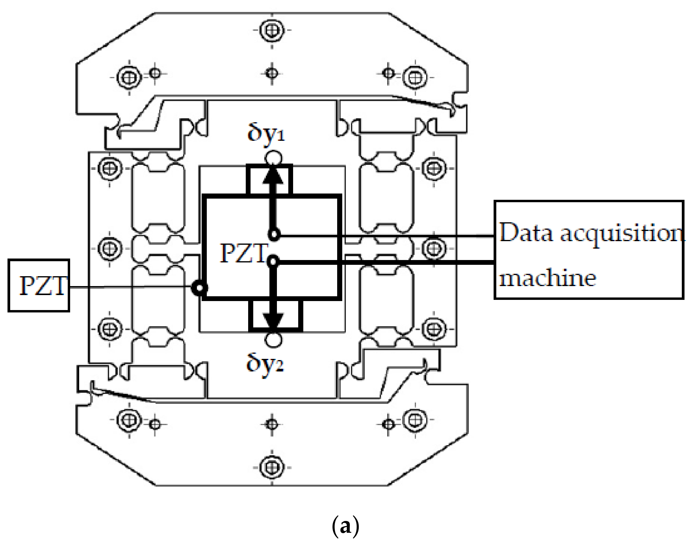
To study the drive performance of the system, a drive performance experiment was performed, as shown in
Figure 4. The experimental apparatus consisted of the experiment box, the PZT, the micro rotary mechanism, the experiment base, two-sided displacement sensors (ZHONGYUAN MEASURING DGC-6PG/A measuring range: ±0.3 mm, total travel: 1~1.5 mm, linear error: ±0.5%, repeatability error: 0.05 μm), and two magnetic table mountains. To avoid external disturbance, the experiment was performed on a vibration isolation platform. In the experimental apparatus, the experiment base was fixed onto the experiment box, and the micro-drive system was fixed onto the experiment base. The driven voltage U was controlled by the control system of the PZT, and sensors 1 and 2 detected the displacement of the system in the direction of the
y-axis, with values of δy
1 and δy
2. The linear motion displacement Δv is:
The drive performance of the system in the ascent stage (the stage with the driven voltage U increasing) and the descent stage (the stage with the driven voltage U decreasing) was tested, and the results of the experiment are shown in
Figure 5a. In addition, the drive performance linear fit of the drive performance is shown in
Figure 5b.
The linear equation fit between the driven voltage U and the linear motion displacement Δv of the system in the ascent stage is:
The linearity of the linear equation is 0.9996.
The linear equation fit between the driven voltage U and the linear motion Δv of the system in the descent stage is:
The linearity of the linear equation is 0.9977.
The drive performance equation can be analyzed from Equations (2) and (3) as:
The minimum linearity of the linear equation is 0.9977.
The drive error of the system δ
1 can be calculated by the slopes of an ascent stage and descent stage through Equation (4), in other words,
where
A1 and
A2 are the slopes of the ascent stage and descent stage of Equation (4).
Therefore, the drive performance Equation (4) was analyzed. The minimum linearity of the linear of the equation was 0.9967, and the drive error of the system (δ1) was 1.47%.
4. The Transformation Performance Analysis of the System
To study the drive performance of the system, three analysis methods were carried out: kinematics analysis, simulation analysis, and experimental analysis.
4.1. Kinematics Analysis
The transformation motion was analyzed by kinematics analysis, as shown below.
If the connecting rod 13 is considered a rigid body, then:
In Equations (7) and (8), (x1,y1) is the initial coordinate of point 1, θ is the included angle between L03 (point 2 is on the line), and R3 is the distance from point 3 to point 0 (R3‘ is also equal to the distance of point 3′ to point 0).
From Equations (6)–(8), then:
If
,
,
, and Equation (9) can be changed to:
When the system has different input linear displacements
driven by the PZT, the corresponding output angular displacements Δθ can be calculated using Equation (12). After placing the initial conditional parameters of the mechanism into Equation (12), the initial conditional parameters are as shown in
Table 2.
Here, (x1, y1) is the coordinate value of point 1. (x4, y4) is the coordinate value of point 4. R2, R3, and R5 are the distance from point 2, point 3, and point 5 to the origin O, respectively. θ2, θ3, and θ5 are the angles of the lines from point 2, point 3, and point 5 to the origin O and the -x-axle, respectively.
Equation (12) is the theory model equation of transformation performance.
4.2. Simulation Analysis
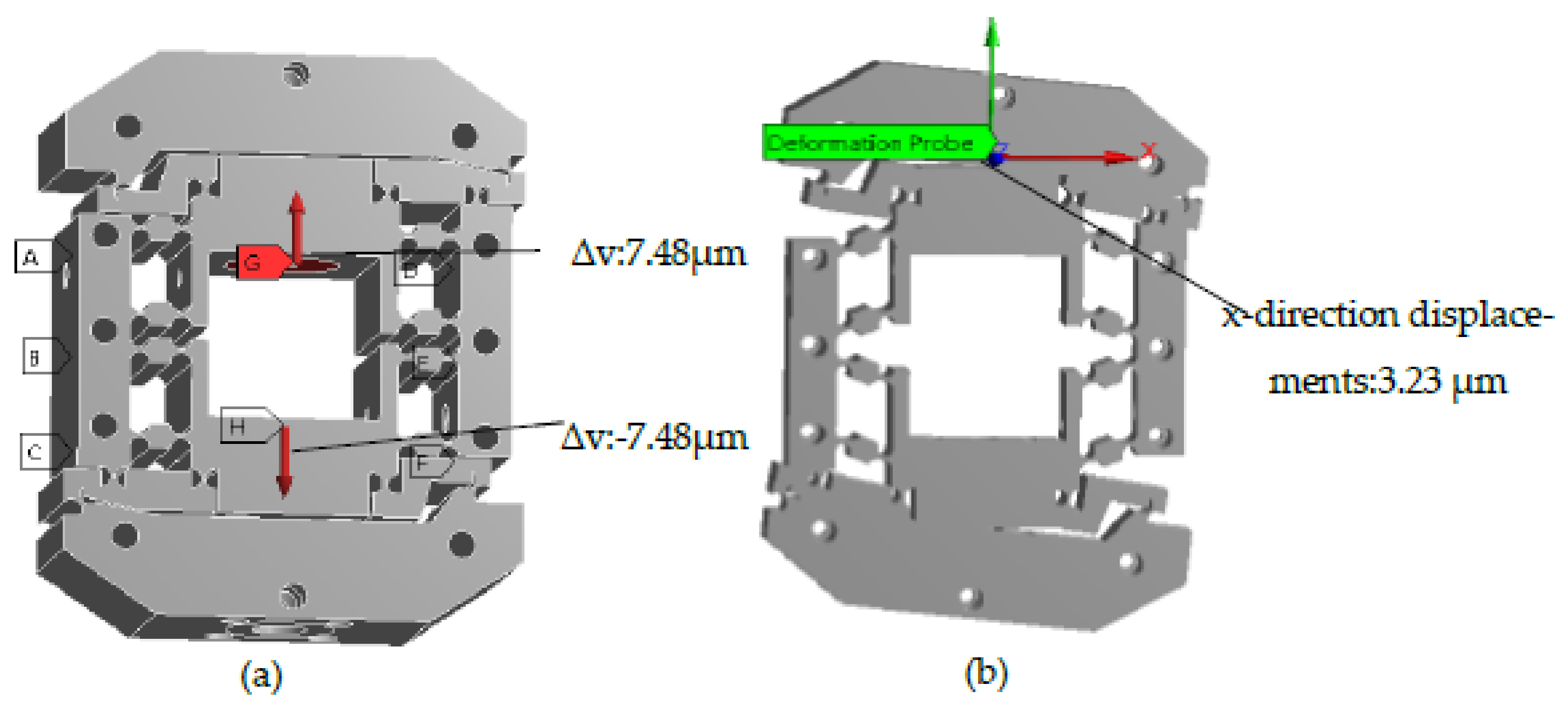
When the transformation performance of the system was analyzed using simulation, the transformation relationship between and Δθ was calculated using the Statics module of ANSYS Workbench.
The 3D model of the micro rotary mechanism was imported into the finite element software. The radius and minimum thickness values of the flexure hinges were 3 mm and 1 mm, and the dimensions of the mechanism were 160 mm × 150 mm × 50 mm (length × width × height). The parameters of 60Si2Mn were chosen as the material properties of the mechanism. To conveniently load the mechanism, the imprint face in the mechanism was constructed, and the structure of the imprint face was fitted to the inner surface between the mechanism and the PZT.
When meshing, the meshing of the entire mechanism was completed using free meshing with 1 mm. Then, refinement grid cells were used for 52 cylinders of flexure hinges with 0.5 mm mesh. After meshing, the number of nodes in the model was 1,590,075, and the number of meshes was 938,699. The meshed model is shown in
Figure 6: the mesh of the arc portion of the flexure hinge was finely divided, and there was no breakage, indicating that the meshing quality was good.
When loading, fixed constraints were placed on the six threaded hole cylinders of M4 in the parts. The loading conditions were the y positive direction and y negative direction displacements with 0.5Δv, which were loaded at the position of the imprint face. The preparation for the ANSYS Workbench analysis is illustrated in
Figure 6.
In the mechanism, the 3D coordinates of the lower surface center point and upper surface center point were defined as (0, 0, 0) and (0, 0, 50). The x-direction displacements of the points were calculated with coordinates (0, 63.5, 50) and (0, −63.5, 50) by the probe method, after which the Δθ of the system could be analyzed. For example, when Δv = 14.96 μm was loaded, the x-direction displacements of the points with coordinates (0, 63.5, 50) and (0, −63.5, 50) were 3.23 μm and −3.30 μm, and Δθ = arctan(0.00653/127) = 10.60″. As a result, when the system input linear displacement was 14.96 μm, the output rotary displacement was 10.60″. In the same way, the output rotary displacements Δθ corresponding to different input linear displacements Δv of the system were calculated. The calculation process is shown in
Figure 7.
The simulation results show that the system can transform linear motion (Δv) into rotary motion (Δθ), and they verify the validity of the theory model Equation (12) of transformation performance.
4.3. Experimental Analysis
To analyze the transformation performance of the system, the transformation performance experiment was performed. The transformation performance experiment is shown in
Figure 8. The experimental apparatus consisted of the experiment box, the PZT, the micro rotary mechanism, the experiment base, two-sided displacement sensors (ZHONGYUAN MEASURING DGC-6PG/A measuring range: ±0.3 mm, total travel: 1~1.5 mm, linear error: ±0.5%, repeatability error: 0.05 μm), two straight displacement sensors (ZHONGYUAN MEASURING DGC-8ZG/C measuring range: ±0.6 mm, total travel: 3 mm, linear error: ±0.5%, repeatability error: 0.03 μm), and four magnetic table mountains. To avoid external disturbance, the experiment was performed on a vibration isolation platform. In the experimental apparatus, the experiment base was fixed onto the experiment box, and the micro-drive system was fixed onto the experiment base.
The linear input displacement △v of the system was determined by calculating the y-direction displacement of the b parts with side sensor 1 (with a value of δy
1) and side sensor 2 (with a value of δy
2). The output angular displacement Δθ of the system was indirectly determined by calculating the x-direction displacement of the d parts with straight sensor 3 (with a value of δx
1) and straight sensor 4 (with a value of δx
2). The experimental results of △v and Δθ were calculated as Equations (13) and (14).
In the experiment, to analyze the transformation performance accurately, 10 groups with Δv and Δθ were detected by different driven voltages of the PZT.
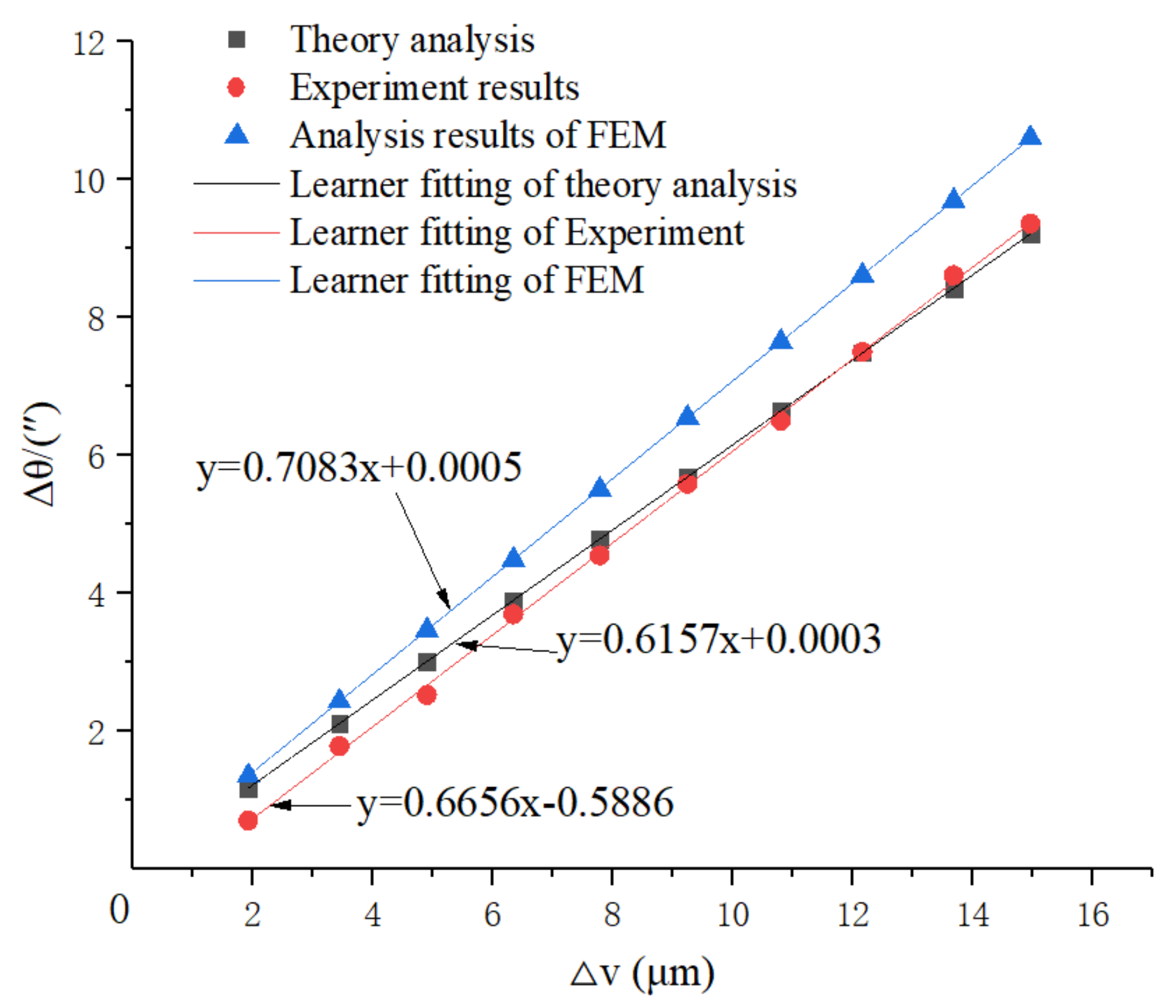
4.4. Comparison and Discussion
To analyze the transformation performance accurately, three methods were used in this paper: the theoretical analysis of theory model Equation (12) of transformation performance in
Section 4.1, the simulation analysis in
Section 4.2, and the experimental analysis. The results of the above three methods in analyzing the relationships between Δv and Δθ were contradictory, as shown in
Figure 9.
The transformation performance linear fit of the drive performance is shown in
Figure 10.
The linear equation fit of the theory analysis is:
The linearity of the linear equation is 1.
The linear equation fit of the simulation analysis is:
The linearity of the linear equation is 1.
The linear equation fit of the experimental analysis is:
The linearity of the linear equation is 0.9997.
Due to model simplification error and mechanical motion error, the analytical results of FEM are different from those of the theory analysis and experimental analysis.
For engineering application convenience (for example, the programming in CNC), the coefficient of Δv in Equations (15)–(17) was averaged because of its good linearity, and the transformation motion of the system can be described as in Equation (18).
The resolution of the angular motion of the system can be calculated from the resolution of the piezoelectric ceramics in
Table 1 (converted from nanometer to micron) combined with Equation (18):
. Therefore, the resolution of the angular motion of the system is 0.00019″.
According to the results of the transformation performance analysis, the following conclusions can be made:
(1) The transformation motion can be described as in Equation (18), which can be conveniently applied in practical engineering problems.
(2) The transformation maximum error of the system (δ2) is 7.50%. From Equations (15)–(17), the error between the theoretical analysis and the experiment analysis is 7.5131% (calculated by the slopes of Equations (15) and (17)), and the error between the simulation analysis and experimental analysis is 6.42% (calculated by the slopes of Equations (16) and (17)); therefore, the maximum error (δ2) of the transformation motion is 7.50%.
(3) The minimum linearity of the transformation performance Equation (18) is 0.9997.
5. The Positioning Performance Analysis of the System
For the positioning motion of the micro rotary system, the linear displacement Δv is driven by the PZT with the driven voltage U based on the drive motion, and the rotary displacement Δθ is transformed by the micro rotary mechanism with the linear input displacement Δv based on the transformation motion. The positioning performance of the micro rotary system is focused on the relationship between the driven voltage U and the rotary displacement Δθ (i.e., the functional relationship between Δv and Δθ).
The drive motion equation of the system in Equation (4), the transformation motion equation of the system in Equation (18), and the positioning motion equation of the system can be analyzed as:
The minimum linearity of Equations (4) and (18) is 0.9977 and 0.9997. Therefore, the minimum linearity of Equation (19) is 0.9974.
The positioning motion is expressed as Equation (19).
If the positioning error of the system is δ, then:
Placing δ1 = 1.47% and δ2 = 7.50% into Equation (20), the positioning error of the system is δ = 8.86%.
Inserting the maximum driven voltage U
max = 10 V and the positioning error δ = 8.86% into Equation (20), the maximum rotary motion displacement matrix A is:
In Equation (21), Δθ1max and Δθ2max are the maximum output rotary displacements in the ascent and descent stages, and e1max and e2max are the maximum positioning error values in the ascent and descent stages.
The maximum rotary motion displacement of the system is shown in
Figure 11.
According to the results of the positioning performance analysis, the following conclusions can be made.
(1) The positioning motion can be expressed as Equation (19), in which the minimum linearity is 0.9974.
(2) The system can provide precision motion at the sub-arc-second level as the maximum positioning error value of the system is 0.85″.
(3) The maximum output rotary displacement of the system is 9.56″ with a positioning error of 8.86%, so the positioning range of the system is approximately 0″–9.56″.
(4) In comparison with other studies, the positioning accuracy achieved in this study is higher and can reach the sub-arc-second level, as shown in
Table 3.
6. Conclusions
This paper proposes a micro-drive rotary system that can transform linear motion into rotary motion with ultrahigh precision. Meanwhile, the positioning performance of the system was analyzed based on the performance analysis of drive motion and transformation motion. The simulation and experimental results show that the positioning accuracy can reach the sub-arc-second level and the positioning performance is excellent.
By transforming linear motion into rotary motion, the system can provide precision motion at the sub-arc-second level, with a maximum positioning error value of 0.85″. The positioning motion Equation (20) is given, the minimum linearity of which is 0.9974, and the maximum output rotary displacement of the system is 9.56″ with a positioning error of 8.86%. The results indicate that the position performance of the system is excellent.
The sub-arc-second micro-drive rotary system can independently provide ultrahigh rotary precision motion, and can also compensate for the motion error of the macro-drive rotary system to form a large-scale sub-arc-second macro/micro dual-drive rotary system. This research is beneficial to the study of rotary motion with sub-arc-second positioning precision, and can help to promote the development of macro/micro dual-drive technology. Future work will be carried out on the all-load-bearing macro/micro dual-drive rotary systems with sub-arc-second motion accuracy.
Author Contributions
Conceptualization, M.Y. and Z.L. (Zhenyang Lv); Methodology, M.Y.; Software, G.J.; Validation, K.W., L.L. and H.G.; Formal Analysis, M.Y.; Investigation, B.F.; Resources, W.G.; Data Curation, Z.L. (Zhenyang Lv); Writing—Original Draft Preparation, M.Y.; Writing—Review and Editing, M.Y. and Y.Y.; Visualization, M.Y.; Supervision, M.Y., W.G., Y.H., B.F. and H.G.; Modification of the Paper, C.Z. and Z.L. (Zhengxiong Lu). All authors have read and agreed to the published version of the manuscript.
Funding
The research was funded by the National Natural Science Foundation of China (No. 51805428 and No. 51705417), the Basic Research Project of Natural Science in Shaanxi Province (No. 2018JQ5205 and No. 2017JM5042), the Key Research and Development Project of Shaanxi Province (No.2016KTZDGY4-01), the Science and Technology Plan Project of Xi’an City (No. 201805036YD14CG20(7)), the Special Scientific Research Project of the Shaanxi Province Department of Education (No. 18JK0528 and No. 17JK0509), and the Science and Technology Plan Project of Beilin District (No. GX2032).
Institutional Review Board Statement
Not applicable.
Informed Consent Statement
Not applicable.
Data Availability Statement
The data presented in this study are available on request from the corresponding author.
Acknowledgments
The authors would like to acknowledge the valuable contributions from Guangpeng Zhang, Xingang Yang and Xuewu Li.
Conflicts of Interest
The authors declare no conflict of interest.
References
- Li, W.; Liu, M.; Ren, Y.; Chen, Q. A high-speed precision micro-spindle use for mechanical micro-machining. Int. J. Adv. Manuf. Technol. 2019, 102, 3197–3211. [Google Scholar] [CrossRef]
- Pinskier, J.; Shirinzadeh, B.; Ghafarian, M.; Das, T.K.; Al-Jodah, A.; Nowell, R. Topology optimization of stiffness constrained flexure-hinges for precision and range maximization. Mech. Mach. Theory 2020, 150, 103874. [Google Scholar] [CrossRef]
- Yuan, J.; Lyu, B.; Hang, W.; Deng, Q. Review on the progress of ultra-precision machining technologies. Front. Mech. Eng. 2017, 12, 158–180. [Google Scholar] [CrossRef]
- Zheng, E.; Zhu, R.; Zhu, S.; Lu, X. A study on dynamics of flexible multi-link mechanism including joints with clearance and lubrication for ultra-precision presses. Nonlinear Dyn. 2016, 83, 137–159. [Google Scholar] [CrossRef]
- Zenia, S.; Ben Ayed, L.; Nouari, M.; Delamézière, A. Numerical prediction of the chip formation process and induced damage during the machining of carbon/epoxy composites. Int. J. Mech. Sci. 2015, 90, 89–101. [Google Scholar] [CrossRef]
- Ahn, H.-J. Eddy current damper type reaction force compensation mechanism for linear motor motion stage. Int. J. Precis. Eng. Manuf. Technol. 2016, 3, 67–74. [Google Scholar] [CrossRef]
- Yu, H.; Liu, Y.; Tian, X.; Zhang, S.; Liu, J. A precise rotary positioner driven by piezoelectric bimorphs: Design, analysis and experimental evaluation. Sens. Actuators A Phys. 2020, 313, 112197. [Google Scholar] [CrossRef]
- Sabarianand, D.; Karthikeyan, P.; Muthuramalingam, T. A review on control strategies for compensation of hysteresis and creep on piezoelectric actuators based micro systems. Mech. Syst. Signal Process. 2020, 140, 106634. [Google Scholar] [CrossRef]
- Yang, W.; Liu, X.; Guo, X.; Lu, W.; Yao, Z.; Lei, Z. A method for simultaneously measuring 6DOF geometric motion errors of a precision rotary stage based on absolute position-distance measurement. Opt. Lasers Eng. 2021, 138, 106420. [Google Scholar] [CrossRef]
- Xu, S.; Shimada, K.; Mizutani, M.; Kuriyagawa, T. Fabrication of hybrid micro/nano-textured surfaces using rotary ultrasonic machining with one-point diamond tool. Int. J. Mach. Tools Manuf. 2014, 86, 12–17. [Google Scholar] [CrossRef]
- Gräser, P.; Linß, S.; Harfensteller, F.; Torres, M.; Zentner, L.; Theska, R. High-precision and large-stroke XY micropositioning stage based on serially arranged compliant mechanisms with flexure hinges. Precis. Eng. 2021, 72, 469–479. [Google Scholar] [CrossRef]
- Wang, J.; Bayanheshig; Zhu, C. Dual-drive long-travel precise positioning stage of grating ruling engine. Int. J. Adv. Manuf. Technol. 2017, 93, 3541–3550. [Google Scholar] [CrossRef]
- Deng, Y.; Jin, X.; Zhang, Z. A macro–micro compensation method for straightness motion error and positioning error of an improved linear stage. Int. J. Adv. Manuf. Technol. 2015, 80, 1799–1806. [Google Scholar] [CrossRef]
- Feng, J.; Gao, F.; Zhao, X.; Yue, Y.; Liu, R. A new macro-micro dual drive parallel robot for chromosome dissection. J. Mech. Sci. Technol. 2012, 26, 187–194. [Google Scholar] [CrossRef]
- Zhuang, X.; Ma, S.; Zhao, Z. A microstructure-based macro-micro multi-scale fine-blanking simulation of ferrite-cementite steels. Int. J. Mech. Sci. 2017, 128–129, 414–427. [Google Scholar] [CrossRef]
- Zhang, J.; Yang, Y.; Lou, J.; Wei, Y.; Fu, L. Development and Hybrid Position/Force Control of a Dual-Drive Macro-Fiber-Composite Microgripper. Sensors 2018, 18, 1301. [Google Scholar] [CrossRef] [PubMed] [Green Version]
- Sun, X.; Yang, B. A new methodology for developing flexure-hinged displacement amplifiers with micro-vibration suppression for a giant magnetostrictive micro drive system. Sens. Actuators A Phys. 2017, 263, 30–43. [Google Scholar] [CrossRef]
- Pham, P.H.; Dang, L.B.; Nguyen, D.T.; Nguyen, D.Q. A micro transmission system based on combination of micro elastic structures and ratchet mechanism. Microsyst. Technol. 2017, 23, 381–387. [Google Scholar] [CrossRef]
- Li, W.; Zhou, Z.; Zhang, B.; Xiao, Y. A micro-coupling for micro mechanical systems. Chin. J. Mech. Eng. 2016, 29, 571–578. [Google Scholar] [CrossRef]
- Yang, B.; Lu, C. Design and analysis of a new three-axis micro-gyroscope. Microsyst. Technol. 2018, 24, 1213–1222. [Google Scholar] [CrossRef]
- Brouwer, D.; de Jong, B.; Soemers, H. Design and modeling of a six DOFs MEMS-based precision manipulator. Precis. Eng. 2010, 34, 307–319. [Google Scholar] [CrossRef]
- Kim, K.; Ahn, D.; Gweon, D. Optimal design of a 1-rotational DOF flexure joint for a 3-DOF H-type stage. Mechatronics 2011, 22, 24–32. [Google Scholar] [CrossRef]
- Qu, J.; Tang, J.; Gianchandani, Y.B.; Oldham, K.R.; Green, S.R. Dynamic modeling of a bidirectional magnetoelastic rotary micro-motor. Sens. Actuators A Phys. 2015, 223, 49–60. [Google Scholar] [CrossRef]
- Xue, G.; Toda, M.; Ono, T. Comb-Drive XYZ-microstage With Large Displacements Based on Chip-Level Microassembly. J. Microelectromech. Syst. 2016, 25, 989–998. [Google Scholar] [CrossRef]
- Liu, M.; Zhang, X.; Fatikow, S. Design and analysis of a multi-notched flexure hinge for compliant mechanisms. Precis. Eng. 2017, 48, 292–304. [Google Scholar] [CrossRef]
- Safa, A.; Abdolmalaki, R.Y.; Shafiee, S.; Sadeghi, B. Adaptive nonsingular terminal sliding mode controller for micro/nanopositioning systems driven by linear piezoelectric ceramic motors. ISA Trans. 2018, 77, 122–132. [Google Scholar] [CrossRef]
- Pham, P.H.; Nguyen, K.T.; Dang, L.B. Design and performance of a high loading electrostatic micro linear motor. Microsyst. Technol. 2015, 21, 2469–2474. [Google Scholar] [CrossRef]
- Peng, Y.X.; Ito, S.; Shimizu, Y.; Gao, W. A Micro-Stage for Linear-Rotary Positioning. Key Eng. Mater. 2012, 523–524, 650–655. [Google Scholar] [CrossRef]
- Peng, Y.; Ito, S.; Sakurai, Y.; Shimizu, Y.; Gao, W. Construction and verification of a linear-rotary microstage with a millimeter-scale range. Int. J. Precis. Eng. Manuf. 2013, 14, 1623–1628. [Google Scholar] [CrossRef]
- Zhang, L.; Long, Z.; Cai, J.; Fang, J. Design of a linear macro–micro actuation stage considering vibration isolation. Adv. Mech. Eng. 2015, 7. [Google Scholar] [CrossRef]
- Xu, W.; Wu, Y. Piezoelectric actuator for machining on macro-to-micro cylindrical components by a precision rotary motion control. Mech. Syst. Signal Process. 2019, 114, 439–447. [Google Scholar] [CrossRef]
- Liu, W.; Li, X.; Jia, Z.; Li, H.; Ma, X.; Yan, H.; Ma, J. Binocular-vision-based error detection system and identification method for PIGEs of rotary axis in five-axis machine tool. Precis. Eng. 2018, 51, 208–222. [Google Scholar] [CrossRef]
- Iafolla, L.; Filipozzi, M.; Freund, S.; Zam, A.; Rauter, G.; Cattin, P.C. Machine learning-based method for linearization and error compensation of a novel absolute rotary encoder. Measurement 2021, 169, 108547. [Google Scholar] [CrossRef]
- Mou, J.; Su, J.; Huang, T. Research on data synchronization technology between rotary table and fiber optic gyroscope. Measurement 2021, 173, 108579. [Google Scholar] [CrossRef]
| Publisher’s Note: MDPI stays neutral with regard to jurisdictional claims in published maps and institutional affiliations. |
© 2021 by the authors. Licensee MDPI, Basel, Switzerland. This article is an open access article distributed under the terms and conditions of the Creative Commons Attribution (CC BY) license (https://creativecommons.org/licenses/by/4.0/).


