
Numerical Analysis of Space Deployable Structure Based on Shape Memory Polymers

 ,
,
Abstract
:1. Introduction
2. Mechanical Characterization of the E-SMP
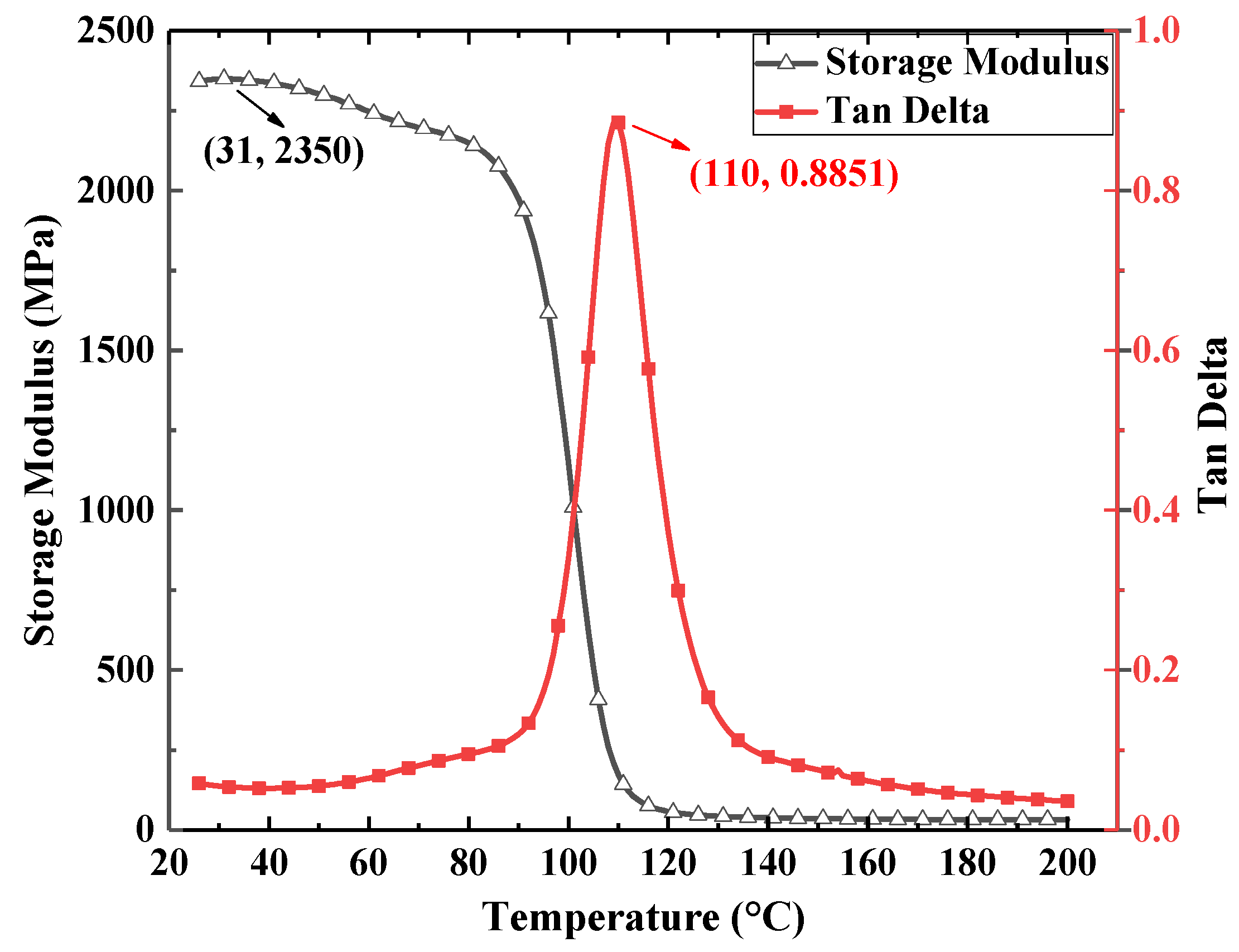
2.1. Dynamic Mechanical Analyzer (DMA)
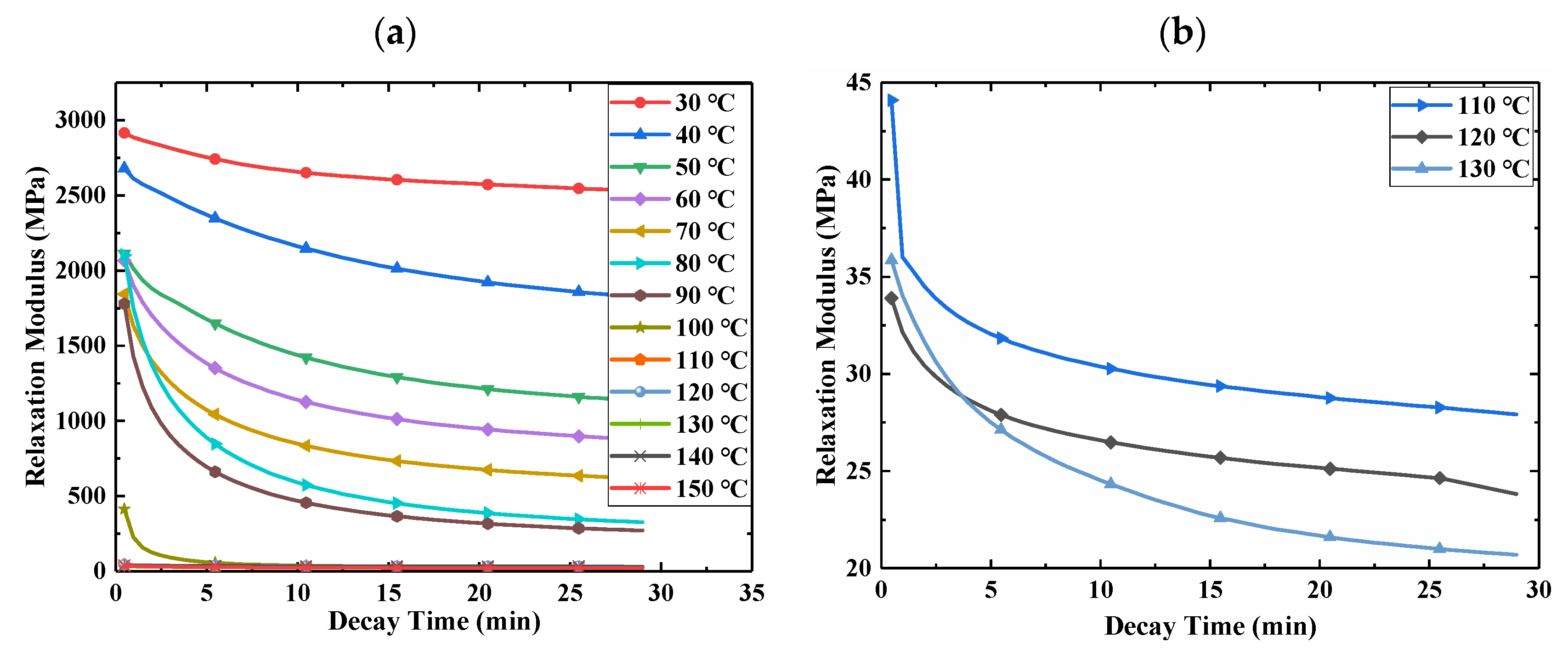
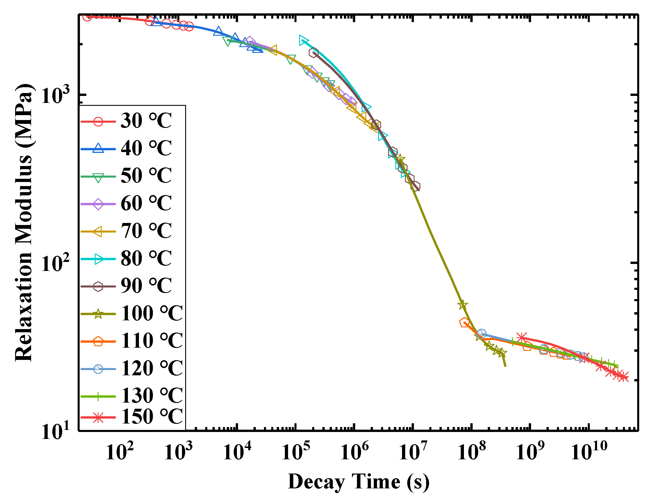
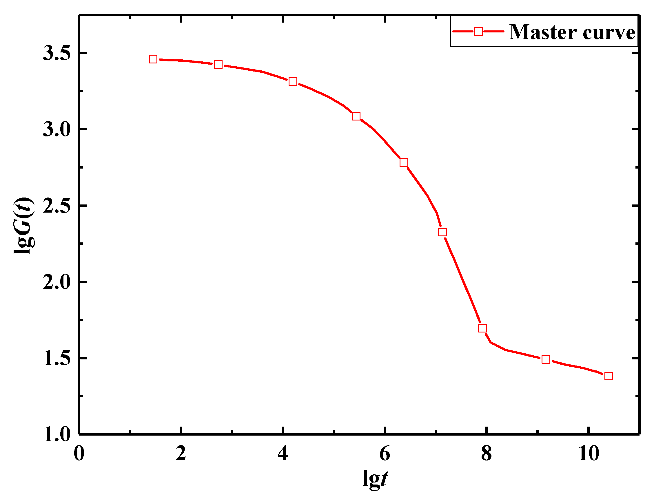
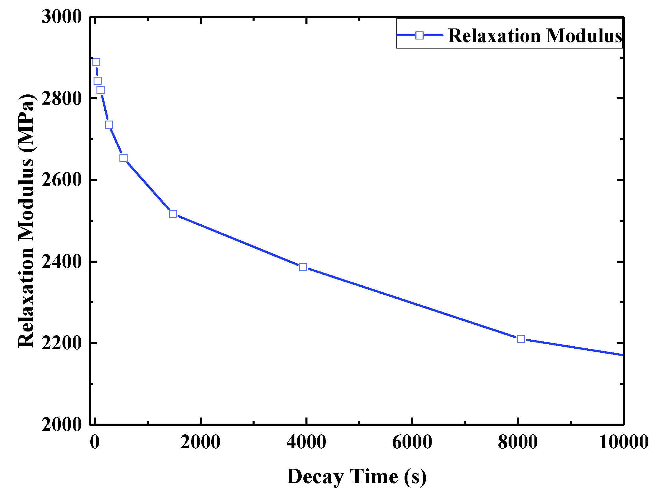
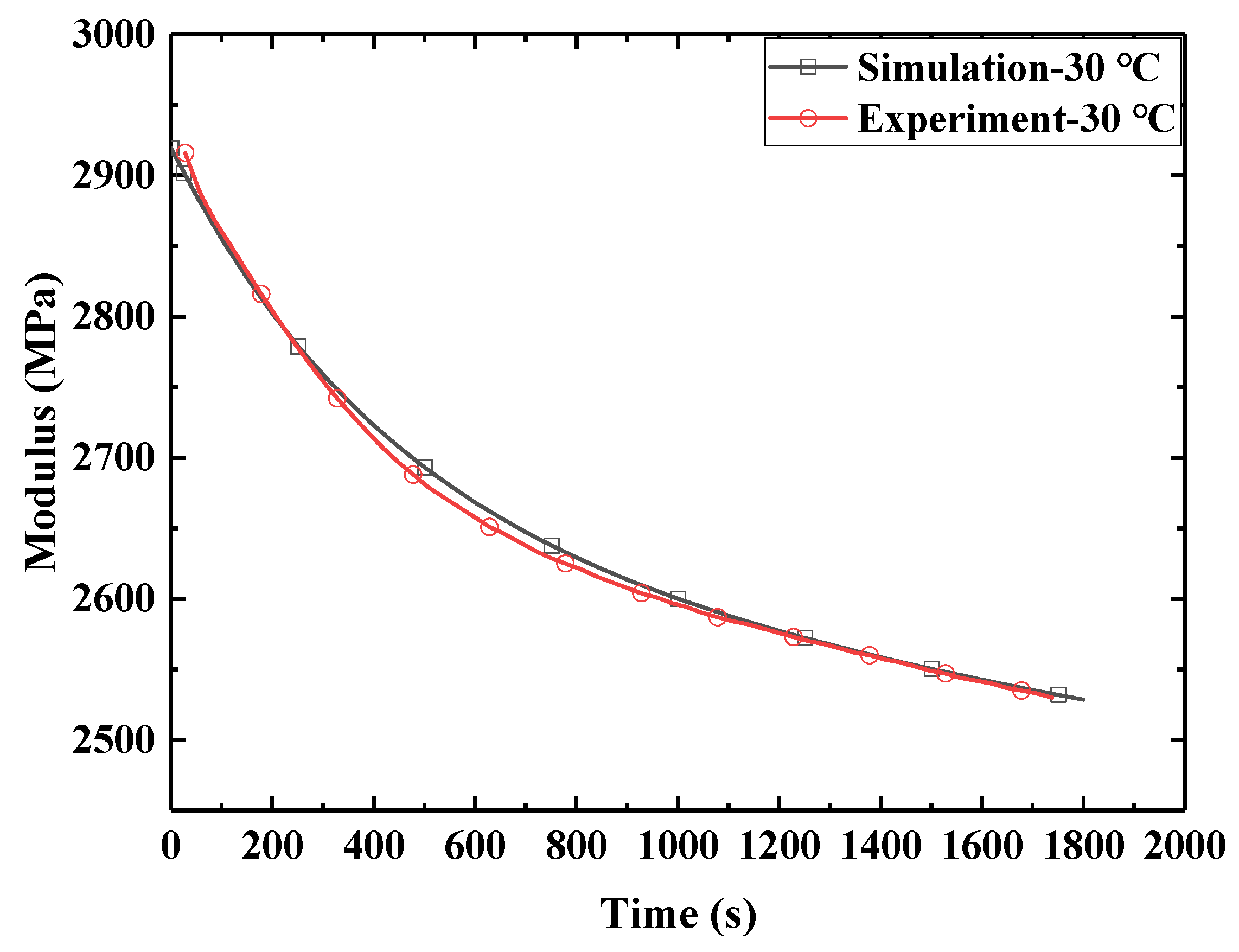
2.2. Relaxation Test
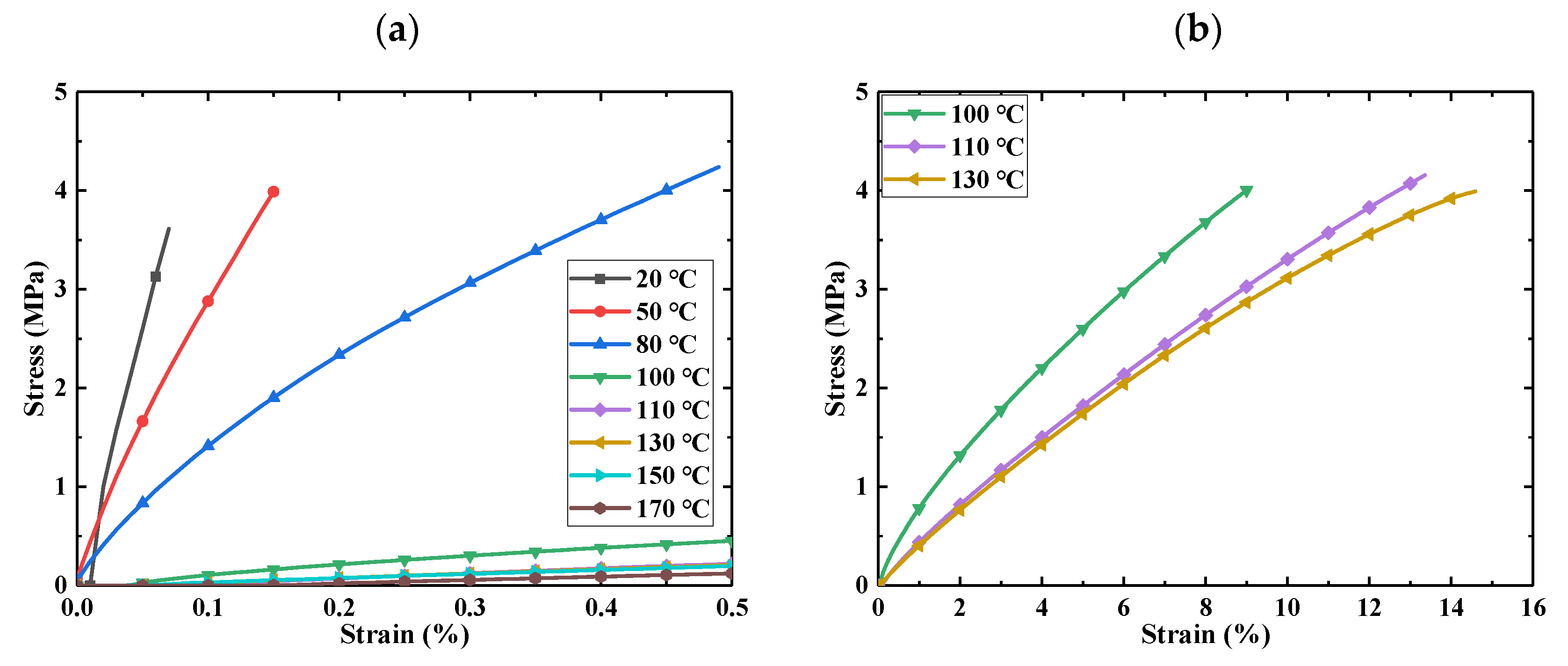
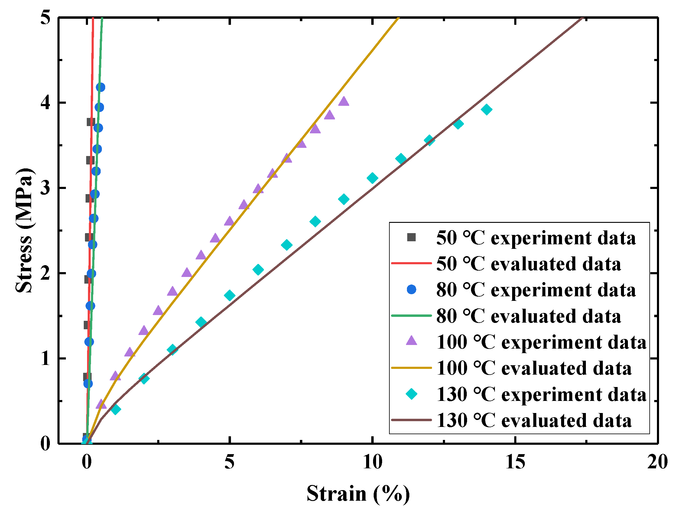
2.3. Tensile Test
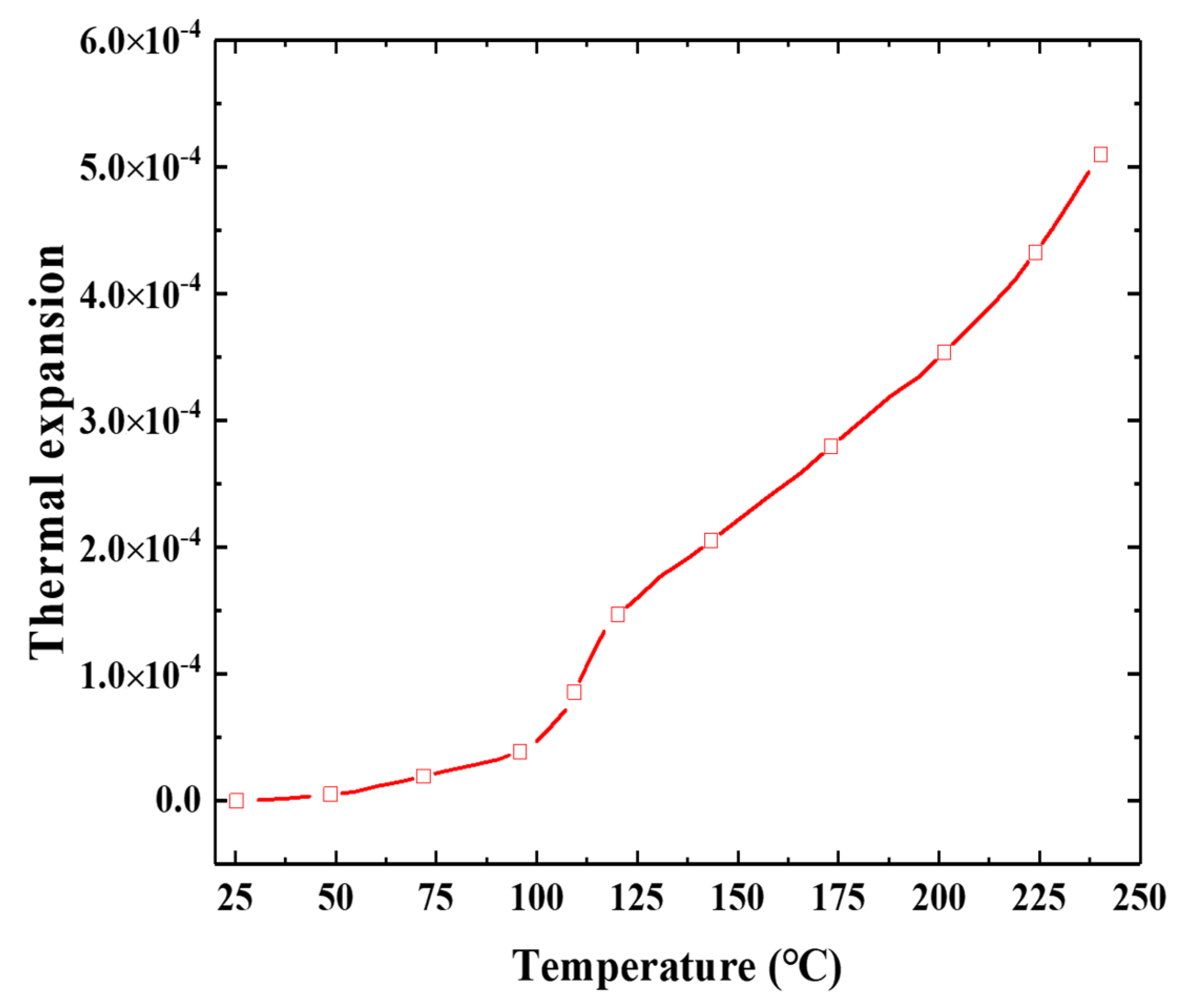
2.4. Thermal Expansion Test
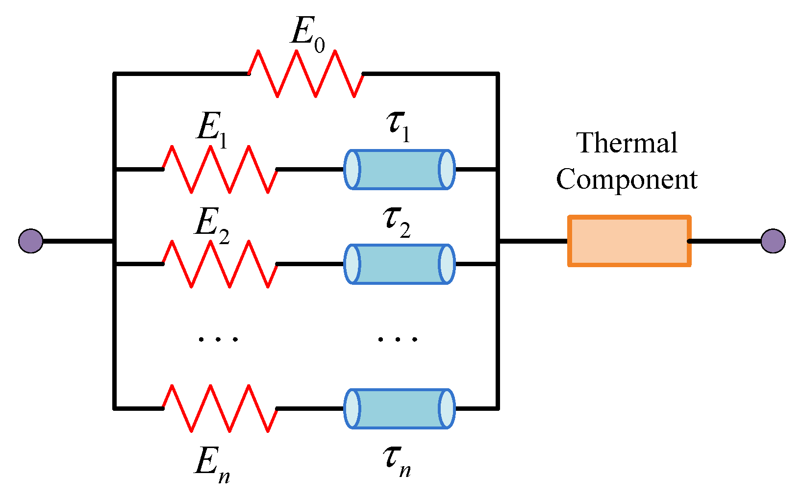
3. Constitutive Modeling of the E-SMP
4. Material Parameters Calibration
4.1. Hyperelastic Parameters Calibration
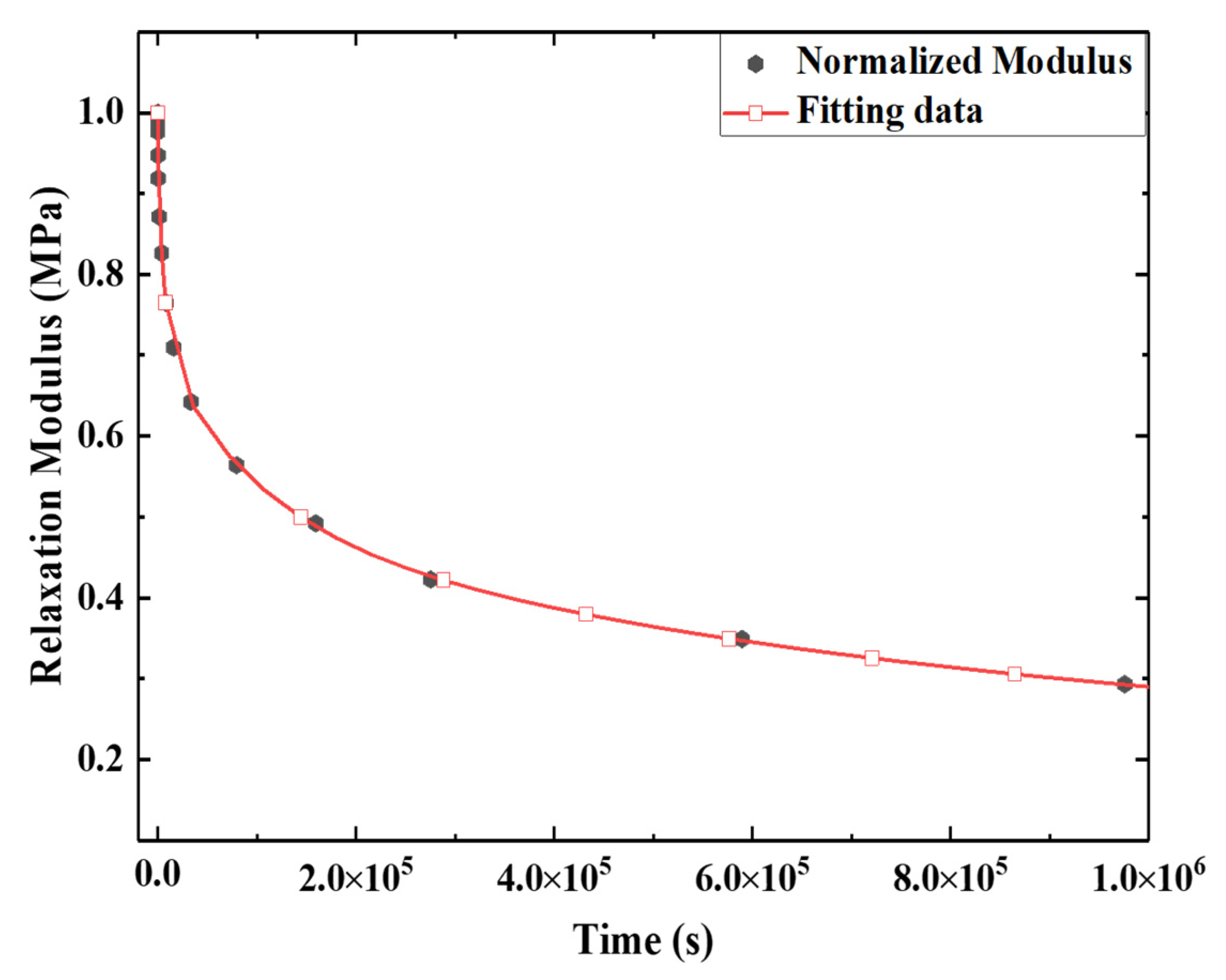
4.2. Viscosity Parameters Calibration
5. Verification of Numerical Analysis
6. Design and Analysis of Deployable Structure
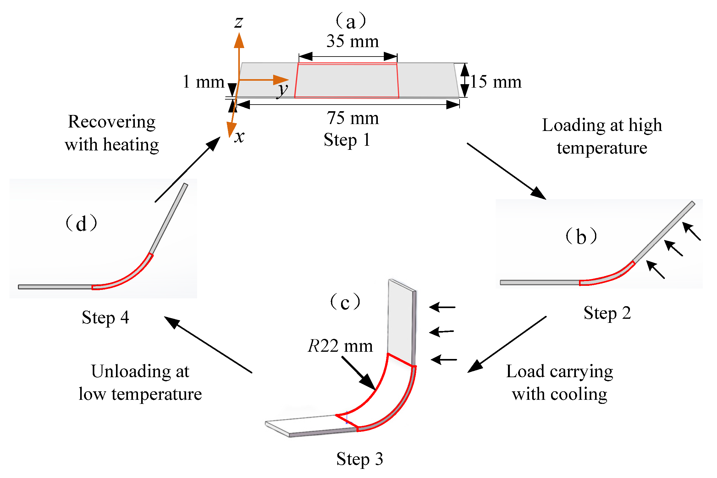
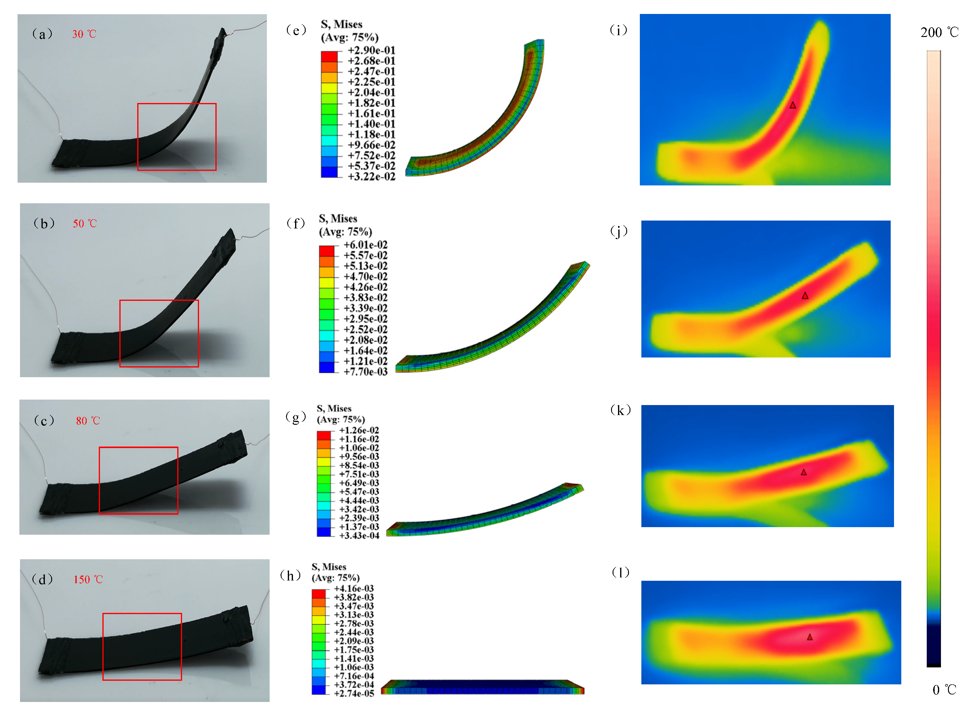
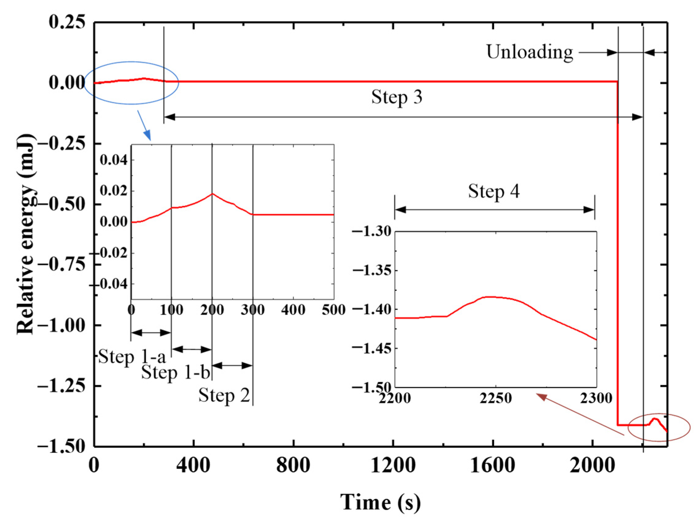
6.1. Design and Analysis of the S-DS
- (1)
- Finite element analysis
- (1)
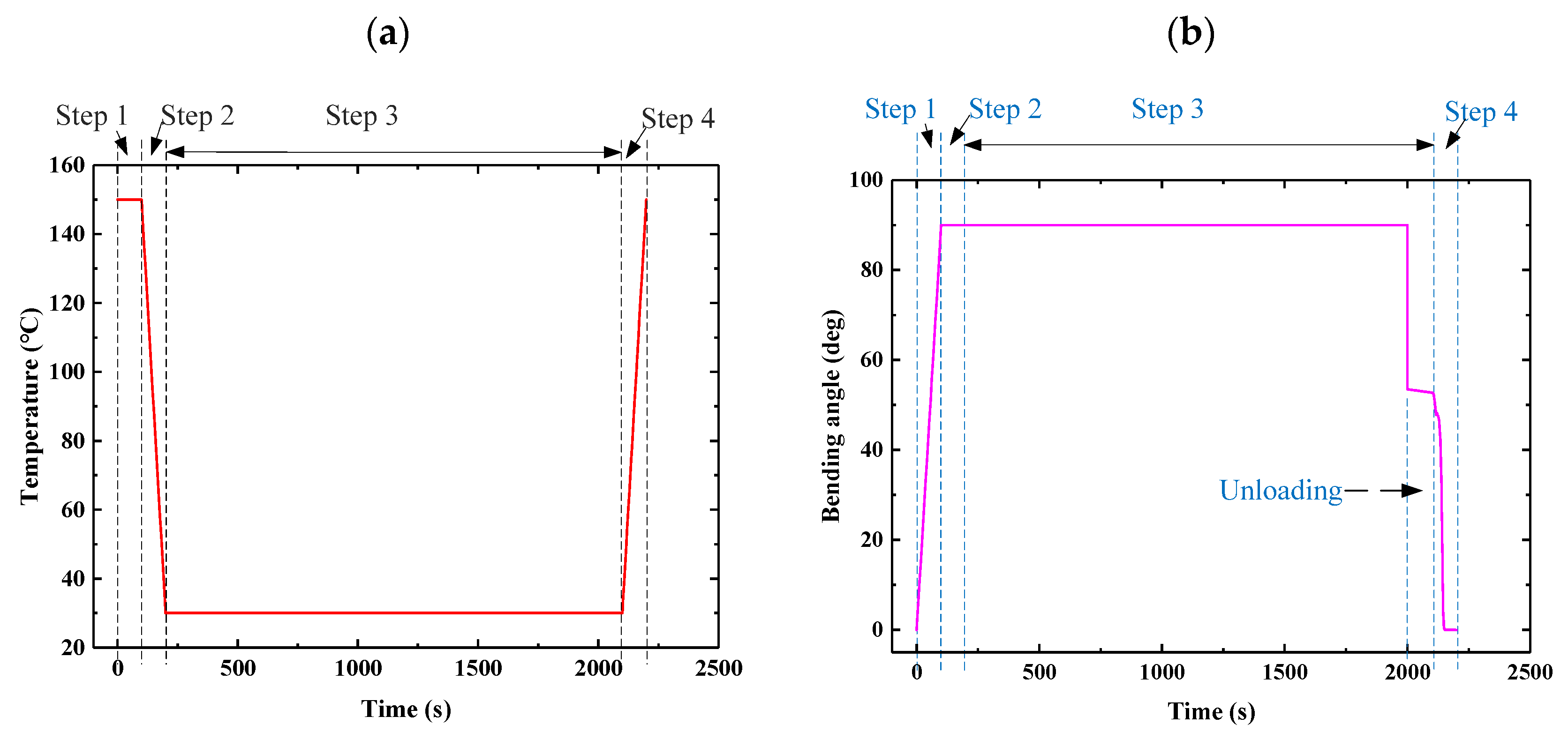
- Loading at high temperature: At 150 °C, one end of the driving structure was fixed and the other end was loaded and bent to 90°, for which the analysis time was 100 s;
- (2)
- Load carrying with cooling: Keeping the load unchanged when the temperature was reduced from 150 °C to 30 °C, the analysis time was 100 s;
- (3)
- Unloading at low temperature: The temperature was kept at 30 °C, then the material was cooled for 1800 s and unloaded;
- (4)
- Recovery with heating: There was no external load interference, the temperature increased from 30 °C to 150 °C, and the analysis time was 100 s.
- (2)
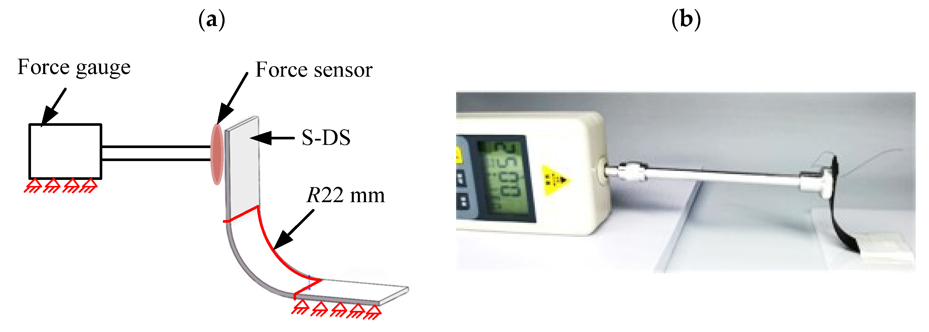
- Analysis of results
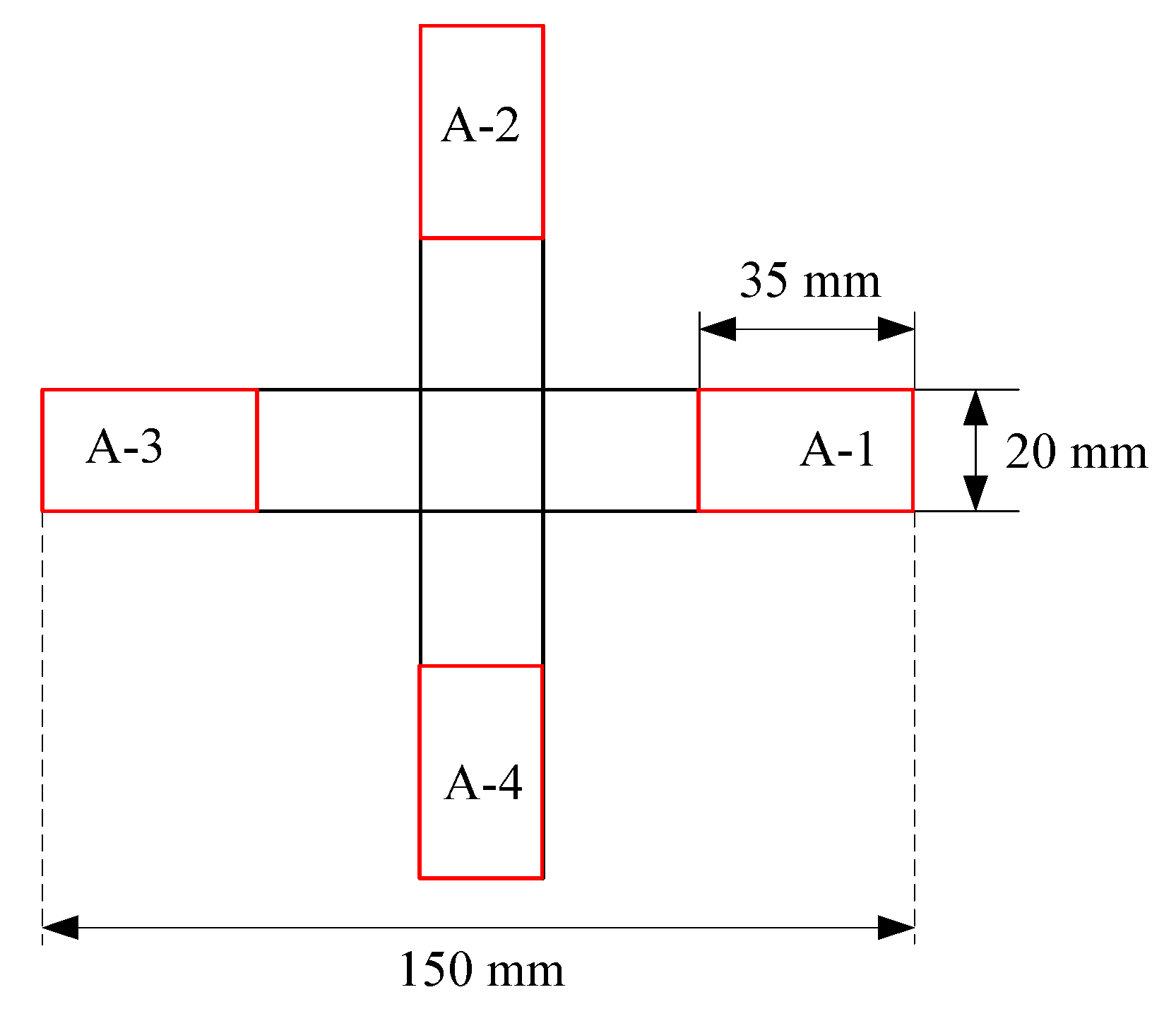
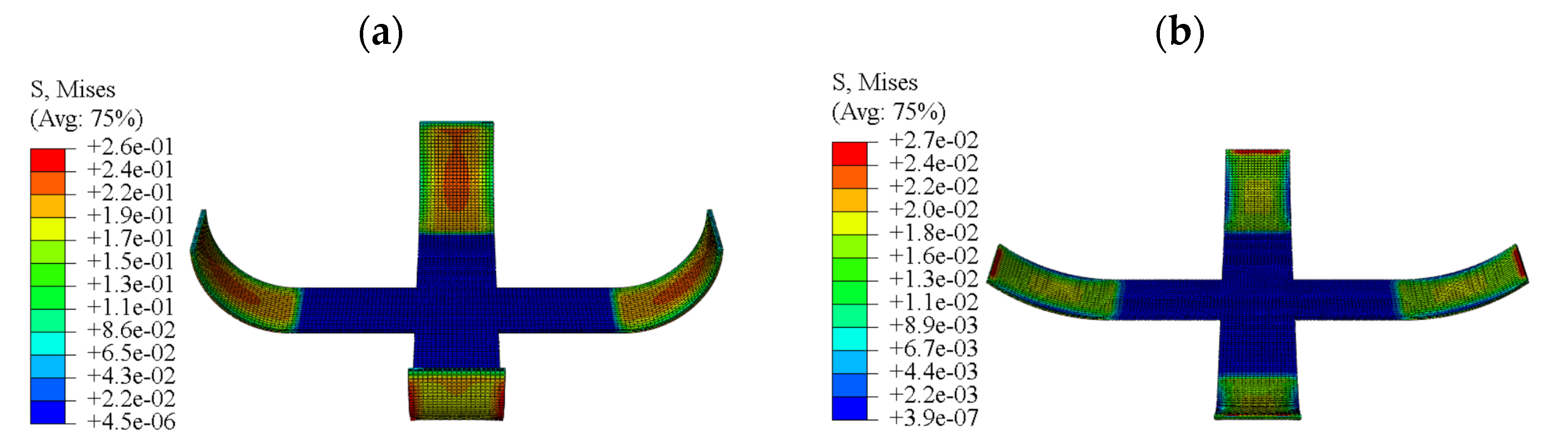
6.2. Design and Analysis of the F-DS
- (1)
- Analysis of the simultaneous driving process
- (2)
- Analysis of the step-by-step driving process
7. Conclusions
Author Contributions
Funding
Conflicts of Interest
Nomenclature
| DMA | Dynamic mechanical analyzer |
| E-SMP | Shape memory polymer materials based on epoxy resin |
| FEM | Finite element method |
| F-DS | Four-arm deployment structure |
| SMPs | Shape memory polymers |
| S-DS | Single-arm deployment structure |
| SMPC | Shape memory polymer composite |
| TTEP | Time–temperature equivalence principle |
| UMAT | User-defined material subroutine |
| WLF | Williams–Lendel–Ferry equation |
| Glass transition temperature |
References
- Lendlein, A.; Jiang, H.; Jünger, O.; Langer, R. Light-induced shape-memory polymers. Nature 2005, 434, 879–882. [Google Scholar] [CrossRef] [PubMed]
- Behl, M.; Kratz, K.; Noechel, U.; Sauter, T.; Lendlein, A. Temperature-memory polymer actuators. Proc. Natl. Acad. Sci. USA 2013, 110, 12555–12559. [Google Scholar] [CrossRef] [PubMed] [Green Version]
- Lin, G.; Jiang, Y.; Hu, J. Bioinspired poly (vinyl alcohol)-silk hybrids: Two-way water-sensitive shape-memory materials. Mater. Today Commun. 2018, 17, 419–426. [Google Scholar] [CrossRef] [Green Version]
- Pan, Z.; Liu, Z. A novel fractional viscoelastic constitutive model for shape memory polymers. J. Polym. Sci. Part B Polym. Phys. 2018, 56, 1125–1134. [Google Scholar] [CrossRef]
- Martin, D.; Hager, A.B.; Stefan, B.; Christine, W.; Ulrich, S. Shape memory polymers: Past, present and future developments. Prog. Polym. Sci. 2015, 49, 3–33. [Google Scholar]
- Behl, M.; Lendlein, A. Shape-memory polymers. Mater. Today 2007, 10, 20–28. [Google Scholar] [CrossRef]
- Santo, L.; Quadrini, F.; Accettura, A.; Villadei, W. Shape Memory Composites for Self-deployable Structures in Aerospace Applications. Procedia Eng. 2014, 88, 42–47. [Google Scholar] [CrossRef]
- Xin, X.; Liu, L.; Liu, Y.; Leng, J. Mechanical Models, Structures, and Applications of Shape-Memory Polymers and Their Composites. Acta Mech. Solida Sin. 2019, 32, 535–565. [Google Scholar] [CrossRef] [Green Version]
- He, Y.; Guo, S.; Liu, Z.; Liew, K.M. Pattern transformation of thermo-responsive shape memory polymer periodic cellular structures. Int. J. Solids Struct. 2015, 71, 194–205. [Google Scholar] [CrossRef]
- Zhao, T.; Kang, G.; Yu, C.; Kan, Q. Experimental study on whole-life one-way shape memory cyclic degradation and fatigue failure of NiTi shape memory alloy. Mater. Today Commun. 2020, 25, 101621. [Google Scholar] [CrossRef]
- Mailen, R.W.; Dickey, M.D.; Genzer, J.; Zikry, M.A. A fully coupled thermo-viscoelastic finite element model for self-folding shape memory polymer sheets. J. Polym. Sci. B Polym. Phys. 2017, 55, 1207–1219. [Google Scholar] [CrossRef]
- Liu, B.; Chen, K.; Zhou, R. Damage evolution and fatigue life prediction of the shape memory alloy under low cycle fatigue. Mater. Today Commun. 2021, 26, 101636. [Google Scholar] [CrossRef]
- Ren, Z.; Ji, L.; Tao, R.; Chen, M.; Wan, Z.; Zhao, Z.; Fang, D. SMP-based multi-stable mechanical metamaterials: From bandgap tuning to wave logic gates. Extrem. Mech. Lett. 2021, 42, 101077. [Google Scholar] [CrossRef]
- Samal, S.; Tyc, O.; Heller, L.; Sittner, P.; Blanco, I. Study of Interfacial Adhesion between Nickel-Titanium Shape Memory Alloy and a Polymer Matrix by Laser Surface Pattern. Appl. Sci. 2020, 10, 2172. [Google Scholar] [CrossRef] [Green Version]
- Samal, S.; Molnárová, O.; Pra, F.; Kopeek, J.; Blanco, I. Net-Shape NiTi Shape Memory Alloy by Spark Plasma Sintering Method. Appl. Sci. 2021, 11, 1802. [Google Scholar] [CrossRef]
- Lin, J.K.H.; Lp, I.D.; Fang, H.; Im, E.; Quijano, U.O. Concept study of a 35-m spherical Reflector System for NEXRAD in Space Application. In Proceedings of the 47th AIAA/ASME/ASCE/AHS/ASC Structures, Structural Dynamics, and Materials Conference, Newport, RI, USA, 1–4 May 2006. [Google Scholar]
- Hu, J.; Yong, Z.; Huang, H.; Jing, L. Recent advances in shape-memory polymers: Structure, mechanism, functionality, modeling and applications. Prog. Polym. Sci. 2012, 37, 1720–1763. [Google Scholar] [CrossRef]
- Liu, Y.; Du, H.; Liu, L.; Leng, L. Shape memory polymers and their composites in aerospace applications: A review. Smart Mater. Struct. 2014, 23, 23001–23022. [Google Scholar] [CrossRef]
- Li, F.; Liu, Y.; Leng, J. Progress of Shape Memory Polymers and Their Composites in Aerospace Applications. Smart Mater. Struct. 2019, 28, 103003. [Google Scholar] [CrossRef]
- Marc, A.L.; Behl, M.; Hiebl, B.; Wischke, C. Shape-memory polymers as a technology platform for biomedical applications. Expert Rev. Med. Devices 2010, 7, 357–379. [Google Scholar]
- Kashyap, D.; Gaur, S.S.; Kanagaraj, S. Development of hybrid shape memory polyurethane composites for endovascular applications, Mater. Today Commun. 2020, 22, 100751. [Google Scholar]
- Liu, R.; Sean, M.; Cui, F.; Luo, X.; Liu, Z. Modelling and simulation of the expansion of a shape memory polymer stent. Eng. Comput. 2019, 36, 2726–2746. [Google Scholar] [CrossRef]
- Hu, J.; Chen, S. A review of actively moving polymers in textile applications. J. Mater. Chem. 2010, 20, 3346–3355. [Google Scholar] [CrossRef]
- Li, G.; Ajisafe, O.; Meng, H. Effect of strain hardening of shape memory polymer fibers on healing efficiency of thermosetting polymer composites. Polymer 2013, 54, 920–928. [Google Scholar] [CrossRef]
- Song, C.; Ju, J. Reconfigurable mesostructures with prestressing, reverse stiffness and shape memory effects. Extrem. Mech. Lett. 2020, 35, 100625. [Google Scholar] [CrossRef]
- He, Y.; Li, Y.; Liu, Z.; Liew, K.M. Buckling analysis and buckling control of thin films on shape memory polymer substrate. Eur. J. Mech. A Solids 2017, 66, 356–369. [Google Scholar] [CrossRef]
- Weigel, T.; Schinkel, G.; Lendlein, A. Design and preparation of polymeric scaffolds for tissue engineering. Expert Rev. Med. Devices 2006, 3, 835–851. [Google Scholar] [CrossRef] [Green Version]
- Metzger, M.F.; Wilson, T.S.; Schumann, D.; Matthews, D.L.; Maitland, D.J. Mechanical Properties of Mechanical Actuator for Treating Ischemic Stroke. Biomed. Microdevices 2002, 4, 89–96. [Google Scholar] [CrossRef]
- Lendlein, A.; Kelch, S. Shape-memory polymers as stimuli-sensitive implant materials. Clin. Hemorheol. Microcirc. 2005, 32, 105. [Google Scholar] [PubMed]
- Maitland, D.J.; Metzger, M.F.; Schumann, D.; Lee, A.; Wilson, T.S. Photothermal properties of shape memory polymer micro-actuators for treating stroke. Lasers Surg. Med. 2001, 30, 1–11. [Google Scholar] [CrossRef] [PubMed]
- Lerouge, S.; Tabrizian, M.; Wertheimer, M.R.; Marchand, R.; Yahia, H.L. Safety of plasma-based sterilization: Surface modifications of polymeric medical devices induced by Sterrad and Plazlyte processes. Biomed. Mater. Eng. 2002, 12, 3–13. [Google Scholar] [PubMed]
- Nardo, L.D.; Alberti, R.; Cigada, A.; Yahia, L.; Tanzi, M.C.; Farè, S. Shape memory polymer foams for cerebral aneurysm reparation: Effects of plasma sterilization on physical properties and cytocompatibility. Acta Biomater. 2009, 5, 1508–1518. [Google Scholar] [CrossRef]
- Lendlein, A.; Langer, R. Biodegradable, elastic shape-memory polymers for potential biomedical applications. Science 2002, 296, 1673–1676. [Google Scholar] [CrossRef]
- Rickert, D.; Lendlein, A.; Kelch, S.; Franke, R.P.; Moses, M.A. Cell proliferation and cellular activity of primary cell cultures of the oral cavity after cell seeding on the surface of a degradable, thermoplastic block copolymer. Biomed. Eng. Biomed. Tech. 2005, 50, 92–99. [Google Scholar] [CrossRef]
- Rickert, D.; Lendlein, A.; Kelch, S.; Moses, M.A.; Franke, R.P. Expression of MMPs and TIMPs in primary epithelial cell cultures of the upper aerodigestive tract seeded on the surface of a novel polymeric biomaterial. Clin. Hemorheol. Microcirc. 2005, 32, 117–128. [Google Scholar] [PubMed]
- Yakacki, C.M.; Shandas, R.; Lanning, C.; Rech, B.; Eckstein, A.; Gall, K. Unconstrained recovery characterization of shape-memory polymer networks for cardiovascular applications. Biomaterials 2007, 28, 2255–2263. [Google Scholar] [CrossRef] [PubMed] [Green Version]
- Yakacki, C.M.; Shandas, R.; Safranski, D.; Ortega, A.M.; Sassaman, K.; Gall, K. Strong, Tailored, Biocompatible Shape-memory Polymer Networks. Adv. Funct. Mater. 2008, 18, 2428–2435. [Google Scholar] [CrossRef] [Green Version]
- Neffe, A.T.; Hanh, B.D.; Steuer, S.; Lendlein, A. Polymer networks combining controlled drug release, biodegradation, and shape memory capability. Adv. Mater. 2009, 21, 3394–3398. [Google Scholar] [CrossRef] [PubMed]
- Zhang, L.; Du, H.; Liu, L.; Liu, Y.; Leng, J. Analysis and design of smart mandrels using shape memory polymers. Compos. Part B Eng. 2014, 59, 230–237. [Google Scholar] [CrossRef]
- Du, H.; Liu, L.; Zhang, F. Triple-shape memory effect in a styrene-based shape memory polymer: Characterization, theory and application. Compos. Part B Eng. 2019, 173, 106905. [Google Scholar] [CrossRef]
- Shao, L.H.; Zhao, B.; Zhang, Q.; Xing, Y.; Zhang, K. 4D printing composite with electrically controlled local deformation. Extrem. Mech. Lett. 2020, 39, 100793. [Google Scholar] [CrossRef]
- Leng, J.; Lan, X.; Liu, Y.; Du, S. Shape-memory polymers and their composites: Stimulus methods and applications. Prog. Mater. Sci. 2011, 56, 1077–1135. [Google Scholar] [CrossRef]
- Mu, T.; Liu, L.; Lan, X.; Liu, Y.; Leng, J. Shape memory polymers for composites. Compos. Sci. Technol. 2018, 160, 169–198. [Google Scholar] [CrossRef]
- Lan, X.; Liu, Y.; Lv, H.; Wang, X.; Leng, J.; Du, S. Fiber Reinforced Shape-Memory Polymer Composite and Its Application in Deployable Hinge in Space. Smart Mater. Struct. 2009, 18, 024002. [Google Scholar] [CrossRef] [Green Version]
- Hazelton, C.; Gall, K.; Abrahamson, E.; Lake, M.; Denis, R. Development of a Prototype Elastic Memory Composite STEM for Large Space Structures. In Proceedings of the 44th AIAA/ASME/ASCE/AHS/ASC Structures, Structural Dynamics, and Materials Conference, Norfolk, VA, USA, 7–10 April 2003. [Google Scholar]
- Huang, R.; Zheng, S.; Liu, Z.; Ng, T.Y. Recent Advances of the Constitutive Models of Smart Materials-Hydrogels and Shape Memory Polymers. Int. J. Appl. Mech. 2020, 12, 2050014. [Google Scholar] [CrossRef] [Green Version]
- Tobushi, H.; Hashimoto, T.; Hayashi, S.; Yamada, E. Thermomechanical Constitutive Modeling in Shape Memory Polymer of Polyurethane Series. J. Intell. Mater. Syst. Struct. 1997, 8, 711–718. [Google Scholar] [CrossRef]
- Tobushi, H.; Okumura, K.; Hayashi, S. Thermomechanical constitutive model of shape memory polymer. Mech. Mater. 2001, 33, 545–554. [Google Scholar] [CrossRef]
- Li, Y.; Guo, S.S.; He, Y.; Liu, Z. A simplified constitutive model for predicting shape memory polymers deformation behavior. Int. J. Comput. Mater. Sci. Eng. 2015, 4, 762–770. [Google Scholar] [CrossRef]
- Liu, Y.; Gall, K.; Dunn, M.; Greenberg, A.R.; Diani, J. Thermomechanics of shape memory polymers: Uniaxial experiments and constitutive modeling. Int. J. Plast. 2006, 22, 279–313. [Google Scholar] [CrossRef]
- Dong, Y.; Zhu, Y.; Liu, M.; Dong, Q.; Li, R.; Fu, Y. Constitutive model for shape memory polyurethane based on phase transition and one-dimensional non-linear viscoelastic. Mater. Today Commun. 2018, 17, 133–139. [Google Scholar] [CrossRef]
- Lu, H.; Wang, X.; Xiang, Z.; Fu, Y.Q. A cooperative domain model for multiple phase transitions and complex conformational relaxations in polymers with shape memory effect. J. Phys. D Appl. Phys. 2019, 52, 245301. [Google Scholar] [CrossRef]
- Hou, L.; Wu, Y.; Xiao, J.; Guo, B.; Zong, Y. Degeneration and damage mechanism of epoxy-based shape memory polymer under 170 keV vacuum proton irradiation. Polym. Degrad. Stab. 2019, 166, 8–16. [Google Scholar] [CrossRef]
- Ramdas, R.; Vijayalakshmi, K.P.; Munirathnamma, L.M.; Ravikumar, H.B.; Santhosh Kumar, K.S. Shape memory polytriazole elastomers from aromatic monomers; Synthesis and properties. Mater. Today Commun. 2018, 17, 180–186. [Google Scholar] [CrossRef]
- Fan, P.; Chen, W.; Bing, Z.; Hu, J.; Gao, J.; Fang, G.; Peng, F. Formulation and numerical implementation of tensile shape memory process of shape memory polymers. Polymer 2018, 148, 370–381. [Google Scholar] [CrossRef]
- Tao, R.; Yang, Q.S.; He, X.Q.; Liew, K.M. Parametric analysis and temperature effect of deployable hinged shells using shape memory polymers. Smart Mater. Struct. 2016, 25, 115034. [Google Scholar] [CrossRef]
- Liu, T.; Liu, L.; Yu, M.; Li, Q.; Zeng, C.; Lan, X.; Liu, Y.; Leng, J. Integrative hinge based on shape memory polymer composites: Material, design, properties and application-ScienceDirect. Compos. Struct. 2018, 206, 164–176. [Google Scholar] [CrossRef]
- Liu, Z.; Li, Q.; Bian, W.; Lan, X.; Liu, Y.; Leng, J. Preliminary test and analysis of an ultralight lenticular tube based on shape memory polymer composites. Compos. Struct. 2019, 223, 110936. [Google Scholar] [CrossRef]
- Zhao, W.; Liu, L.; Lan, X.; Su, B.; Leng, J.; Liu, Y. Adaptive repair device concept with shape memory polymer. Smart Mater. Struct. 2017, 26, 025027. [Google Scholar] [CrossRef] [Green Version]
- Liu, Y.; Zhang, W.; Zhang, F.; Leng, J.; Pei, S.; Wang, L.; Jia, X.; Cotton, C.; Sun, B. TW Chou Microstructural design for enhanced shape memory behavior of 4D printed composites based on carbon nanotube/polylactic acid filament. Compos. Sci. Technol. 2019, 181, 107692.1–107692.9. [Google Scholar] [CrossRef]
- Liu, Q.; Wang, C.; Yamaguchi, T. Study on the Time-Temperature Equivalent Principle for Rocks. In Elsevier Geo-Engineering Book Series; Elsevier: Amsterdam, The Netherlands, 2004; pp. 501–506. [Google Scholar]
- Chen, J.; Liu, L.; Liu, Y.; Leng, J. Thermoviscoelastic shape memory behavior for epoxy-shape memory polymer. Smart Mater. Struct. 2014, 23, 055025. [Google Scholar] [CrossRef]
- Diani, J.; Gilormini, P.; Frédy, C.; Rousseau, I. Predicting thermal shape recovery of crosslinked polymer networks from linear viscoelasticity. Int. J. Solids Struct. 2012, 49, 793–799. [Google Scholar] [CrossRef] [Green Version]
- Tobolsky, A.V.; Mclouglin, J.R. Elastoviscous properties of polyisobutylene (and other amorphous polymers) from stress-relaxation studies: IX. A summary of results. J. Polym. Sci. 1956, 19, 111–121. [Google Scholar] [CrossRef]
- Williams, M.L.; Landel, R.F.; Ferry, J.D. The temperature dependence of relaxation mechanisms in amorphous polymers and other glass-forming liquids. J. Am. Chem. Soc. 1955, 77, 3701–3707. [Google Scholar] [CrossRef]
- Bashandeh, K.; Lee, J.; Wu, Q.; Li, Y.; Polycarpou, A.A. Mechanics and deformation of shape memory polymer kirigami microstructures. Extrem. Mech. Lett. 2020, 39, 100831. [Google Scholar] [CrossRef]
- Shi, M.; Zhao, J.; Zhang, X.; Wang, H.; Wang, Z.; Xue, G.; Xu, L.; Sun, X. Numerical analysis of mechanical performances of shape memory alloy hybrid composites. Mater. Today Commun. 2021, 27, 102293. [Google Scholar] [CrossRef]
- Gutierrez-Lemini, D. Engineering Viscoelasticity; Springer Science & Business Media: New York, NY, USA, 2014; pp. 116–138. [Google Scholar]


| Temperature (°C) | C10 |
|---|---|
| 50 | 5.548 |
| 80 | 2.285 |
| 100 | 5.99 × 10⁻⁴ |
| 130 | 4.25 × 10⁻⁴ |
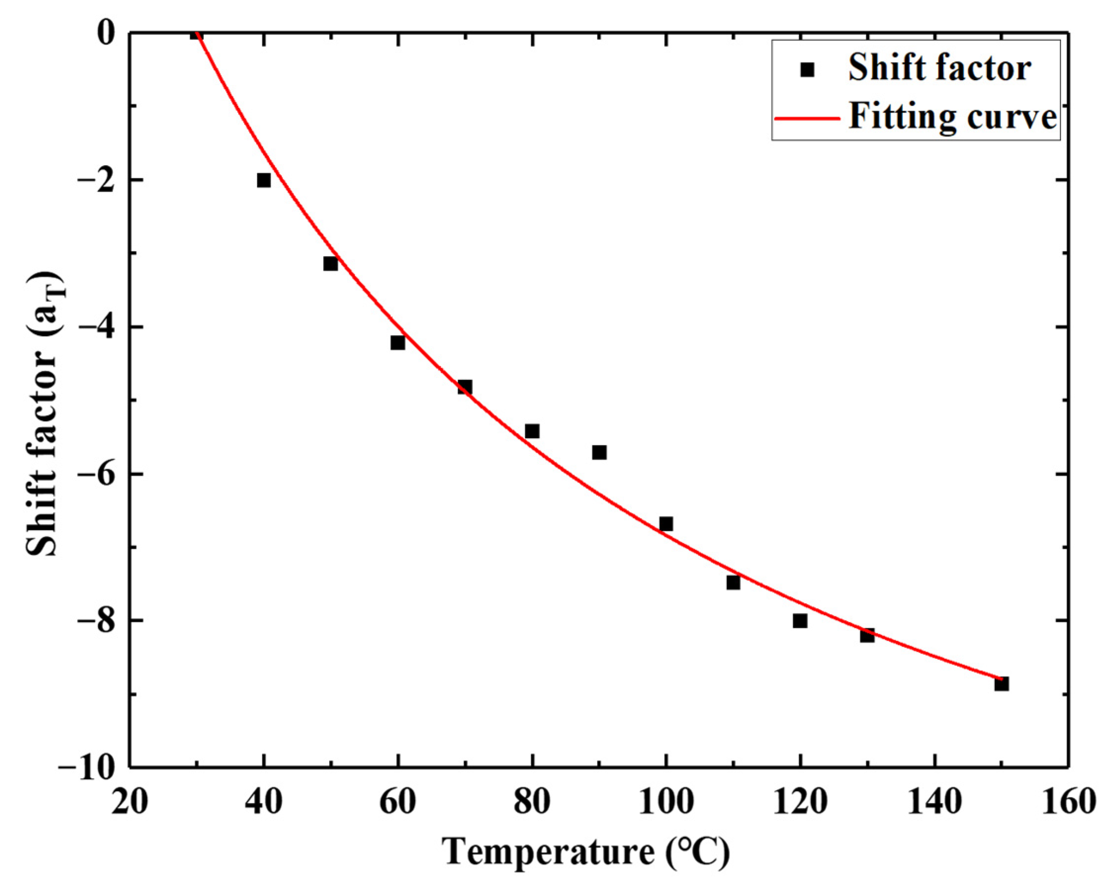
| Temperature (°C) | Shift Factor | Temperature (°C) | Shift Factor |
|---|---|---|---|
| 30 | 0 | 90 | −5.71 |
| 40 | −2.01 | 100 | −6.68 |
| 50 | −3.14 | 110 | −7.48 |
| 60 | −4.22 | 120 | −8.01 |
| 70 | −4.82 | 130 | −8.20 |
| 80 | −5.42 | 150 | −8.86 |
| Reference Temperature (°C) | ||
|---|---|---|
| 30 | 14.664 | 77.636 |
| 9.89 × 10⁻⁴ | 436.82 |
| 0.191 | 9056.2 |
| 0.215 | 1.006 × 10⁵ |
| 0.295 | 8.416 × 10⁵ |
| Group | Recovery Force (N) |
|---|---|
| 1 | 0.041 |
| 2 | 0.045 |
| 3 | 0.047 |
| 4 | 0.052 |
| 5 | 0.055 |
| 6 | 0.058 |
| Average value | 0.049 |
Publisher’s Note: MDPI stays neutral with regard to jurisdictional claims in published maps and institutional affiliations. |
© 2021 by the authors. Licensee MDPI, Basel, Switzerland. This article is an open access article distributed under the terms and conditions of the Creative Commons Attribution (CC BY) license (https://creativecommons.org/licenses/by/4.0/).
Share and Cite
He, Z.; Shi, Y.; Feng, X.; Li, Z.; Zhang, Y.; Dai, C.; Wang, P.; Zhao, L. Numerical Analysis of Space Deployable Structure Based on Shape Memory Polymers. Micromachines 2021, 12, 833. https://doi.org/10.3390/mi12070833
He Z, Shi Y, Feng X, Li Z, Zhang Y, Dai C, Wang P, Zhao L. Numerical Analysis of Space Deployable Structure Based on Shape Memory Polymers. Micromachines. 2021; 12(7):833. https://doi.org/10.3390/mi12070833
Chicago/Turabian StyleHe, Zepeng, Yang Shi, Xiangchao Feng, Zhen Li, Yan Zhang, Chunai Dai, Pengfei Wang, and Liangyu Zhao. 2021. "Numerical Analysis of Space Deployable Structure Based on Shape Memory Polymers" Micromachines 12, no. 7: 833. https://doi.org/10.3390/mi12070833
APA StyleHe, Z., Shi, Y., Feng, X., Li, Z., Zhang, Y., Dai, C., Wang, P., & Zhao, L. (2021). Numerical Analysis of Space Deployable Structure Based on Shape Memory Polymers. Micromachines, 12(7), 833. https://doi.org/10.3390/mi12070833