Review of Recent Development of MEMS Speakers
Abstract
:1. Introduction
2. Theory and Modeling of MEMS Speakers
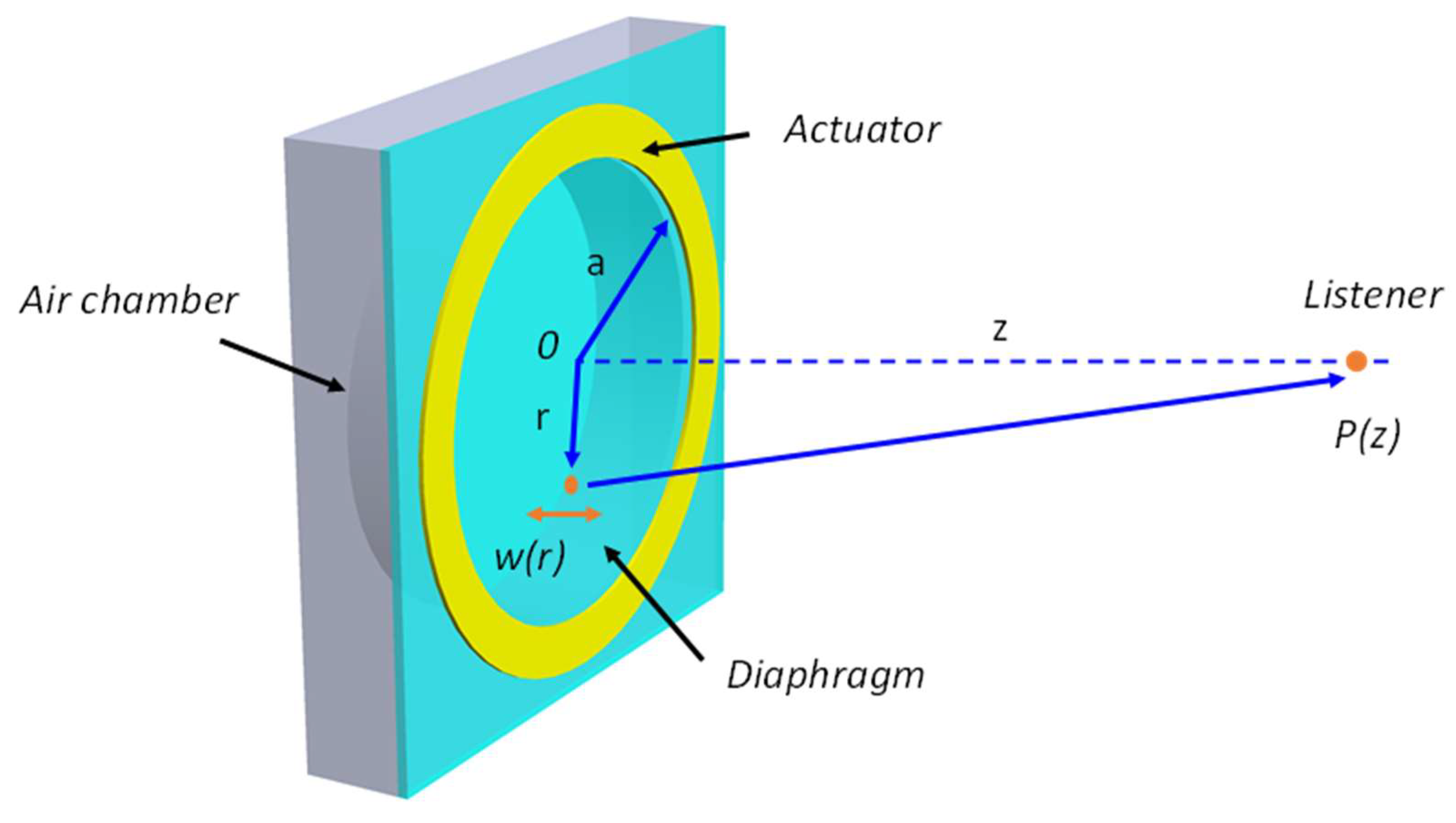
2.1. Basic Structure
2.2. Transduction Mechanisms
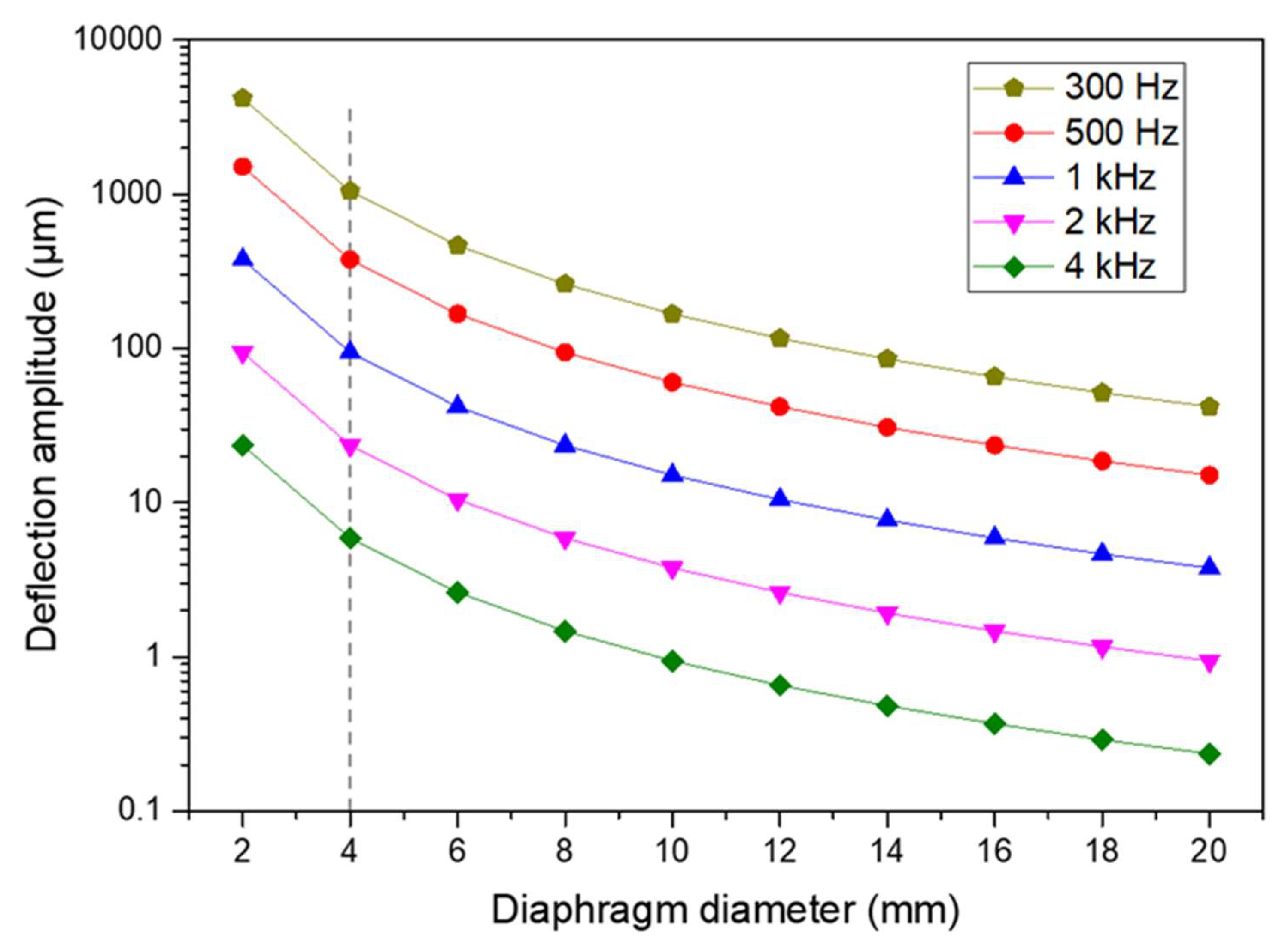
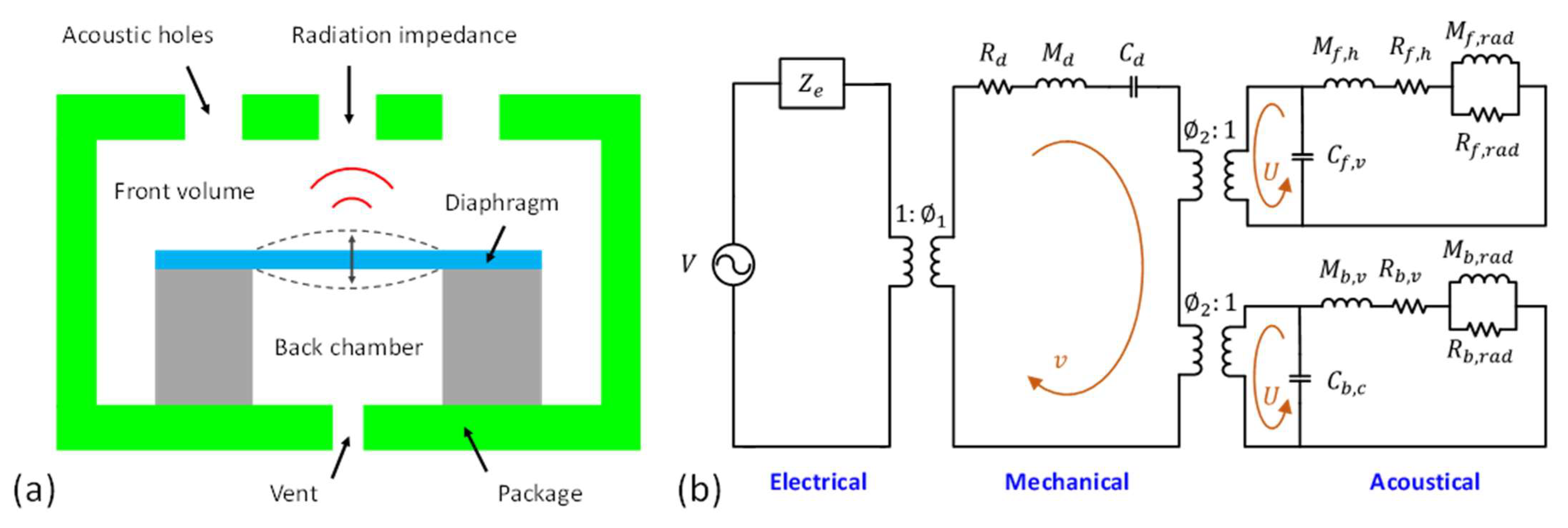
2.3. Modeling
3. Development of MEMS Speakers
3.1. Piezoelectric MEMS Speakers
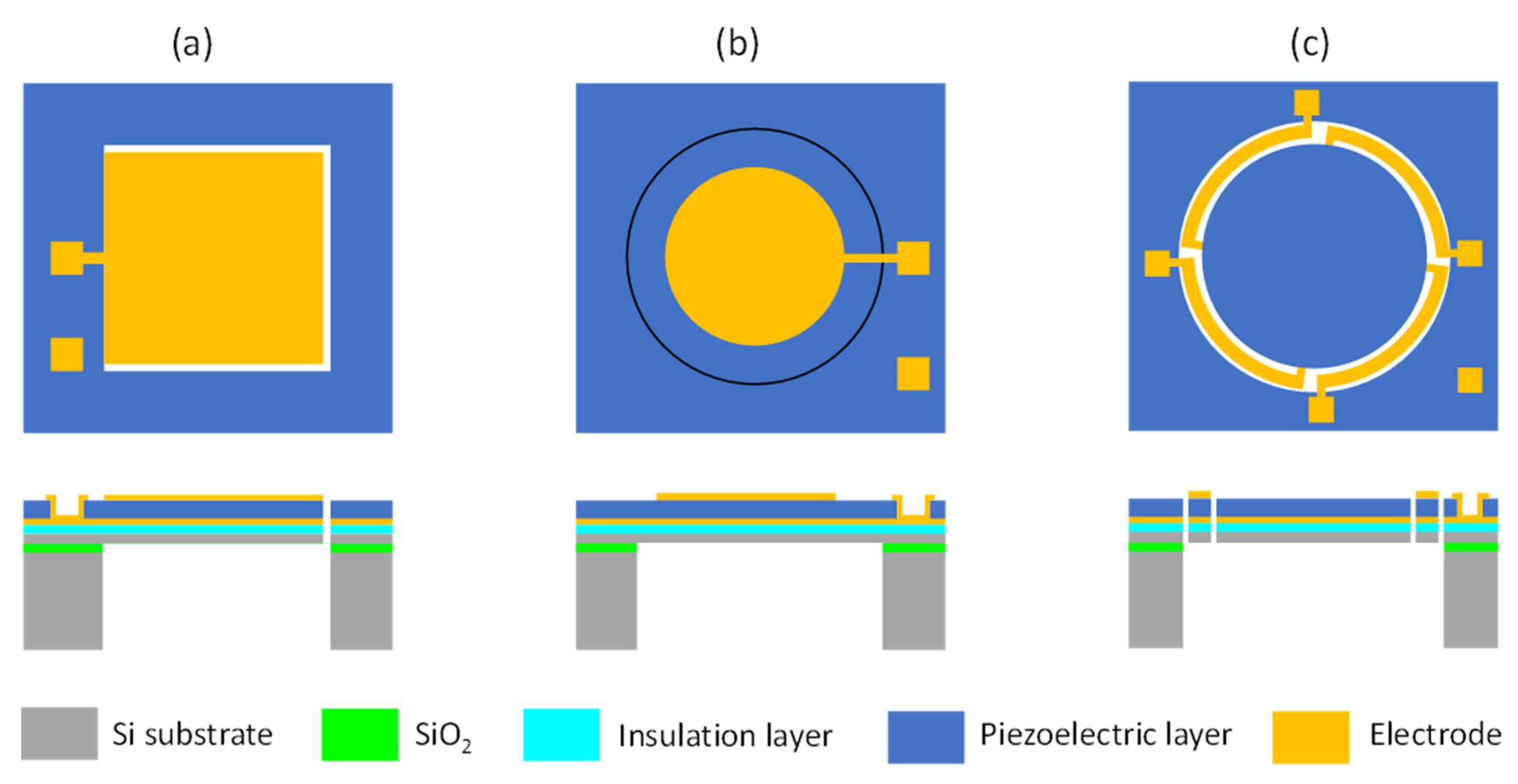
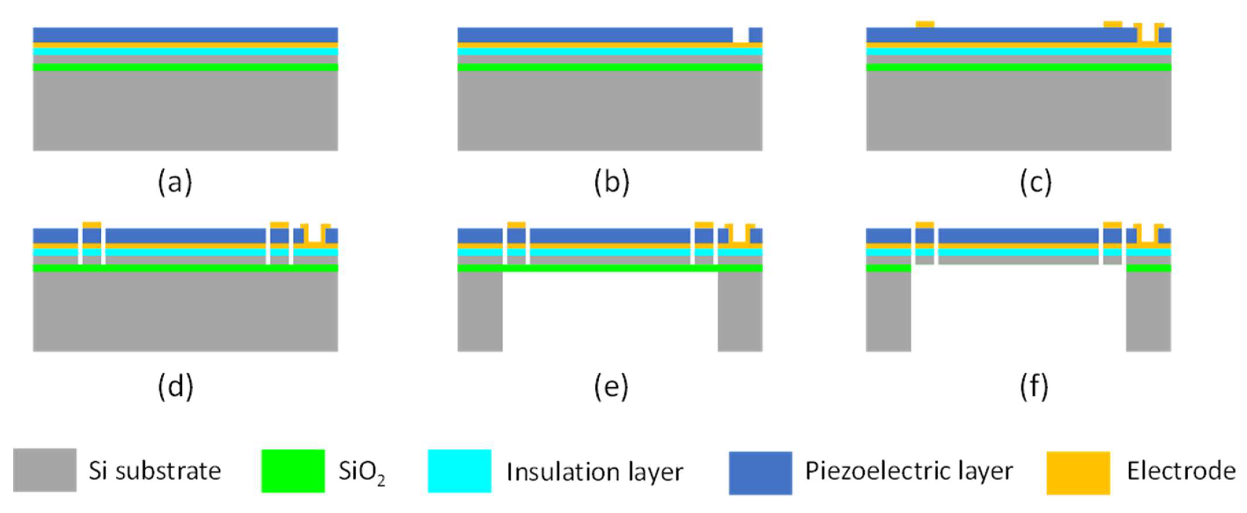
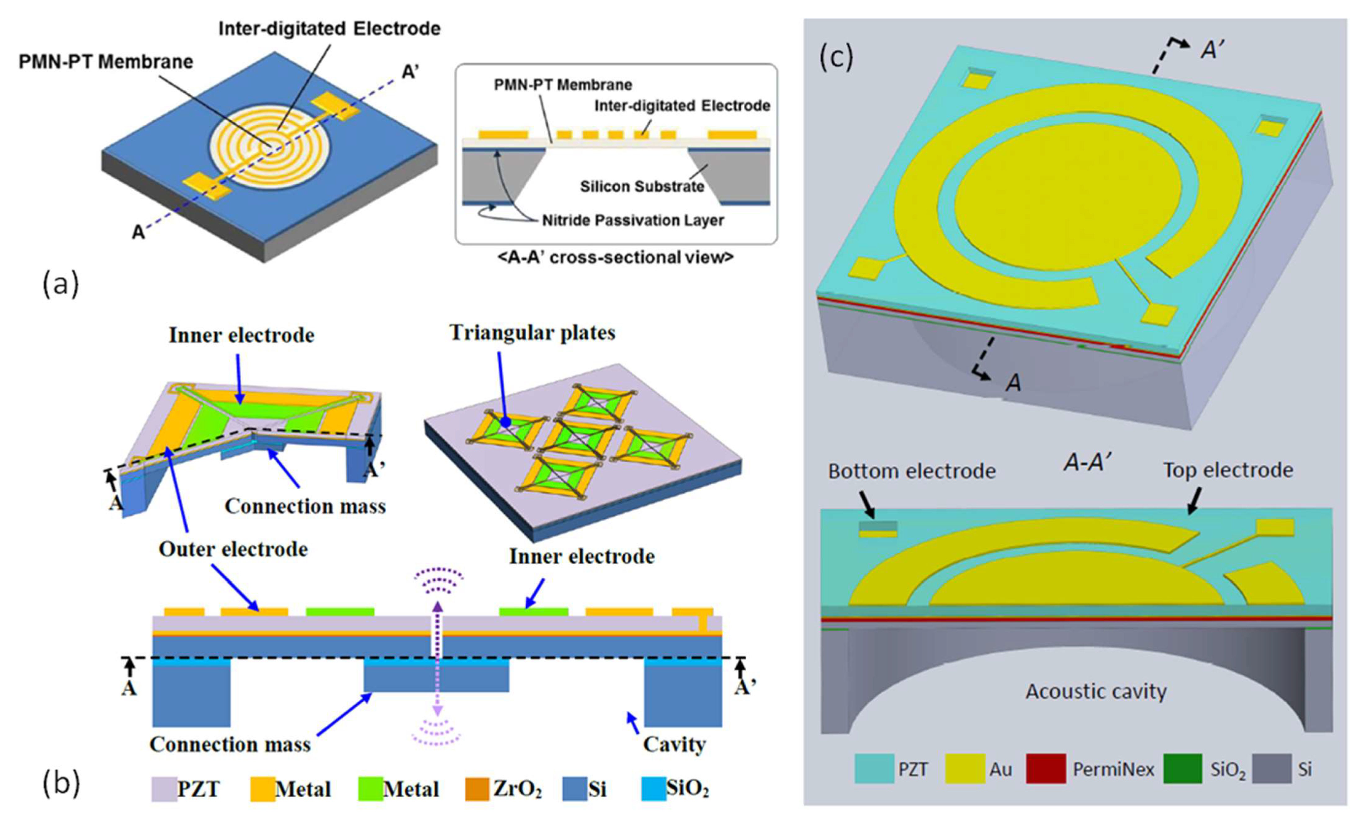
3.1.1. Design and Fabrication of Piezoelectric MEMS Speakers
3.1.2. Piezoelectric Materials
3.1.3. Approaches to Improve SPLs
3.1.4. Summary of Piezoelectric MEMS Speakers
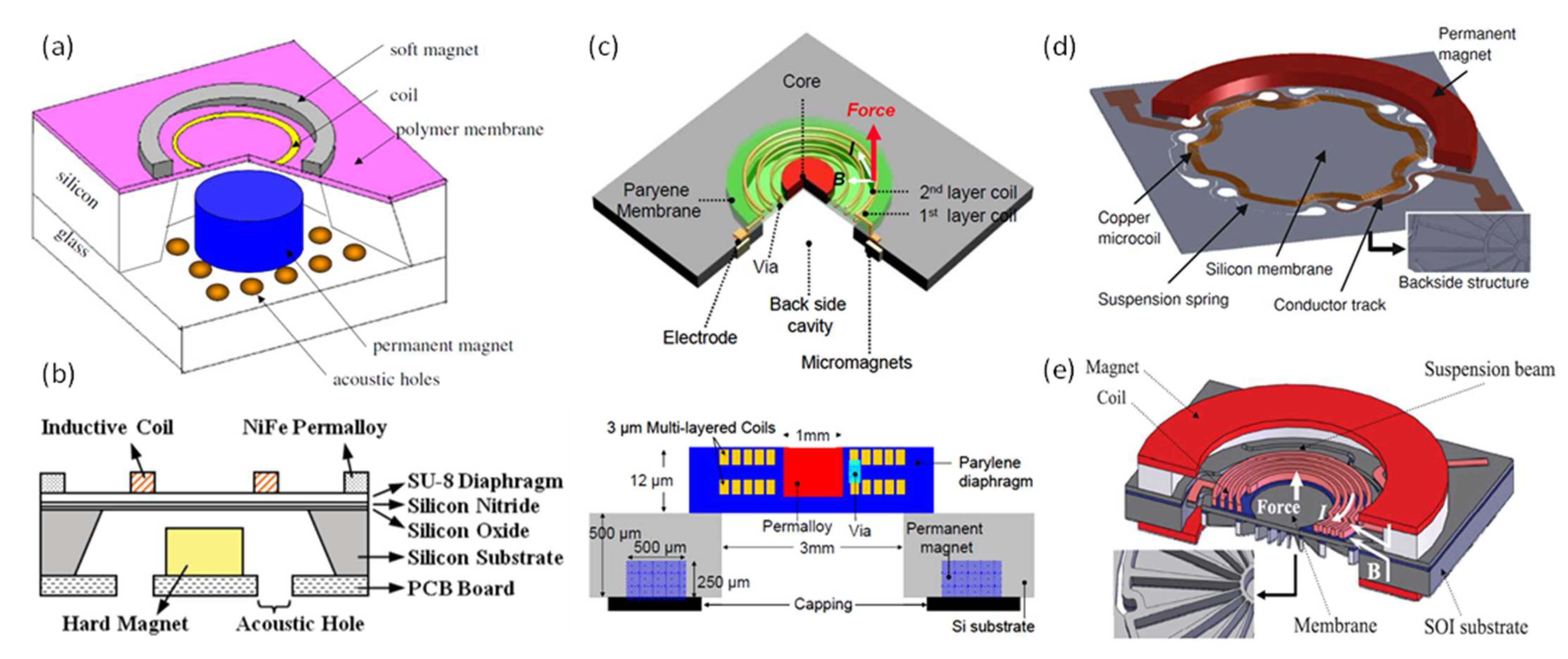
3.2. Electrodynamic MEMS Speakers
3.3. Electrostatic MEMS Speakers
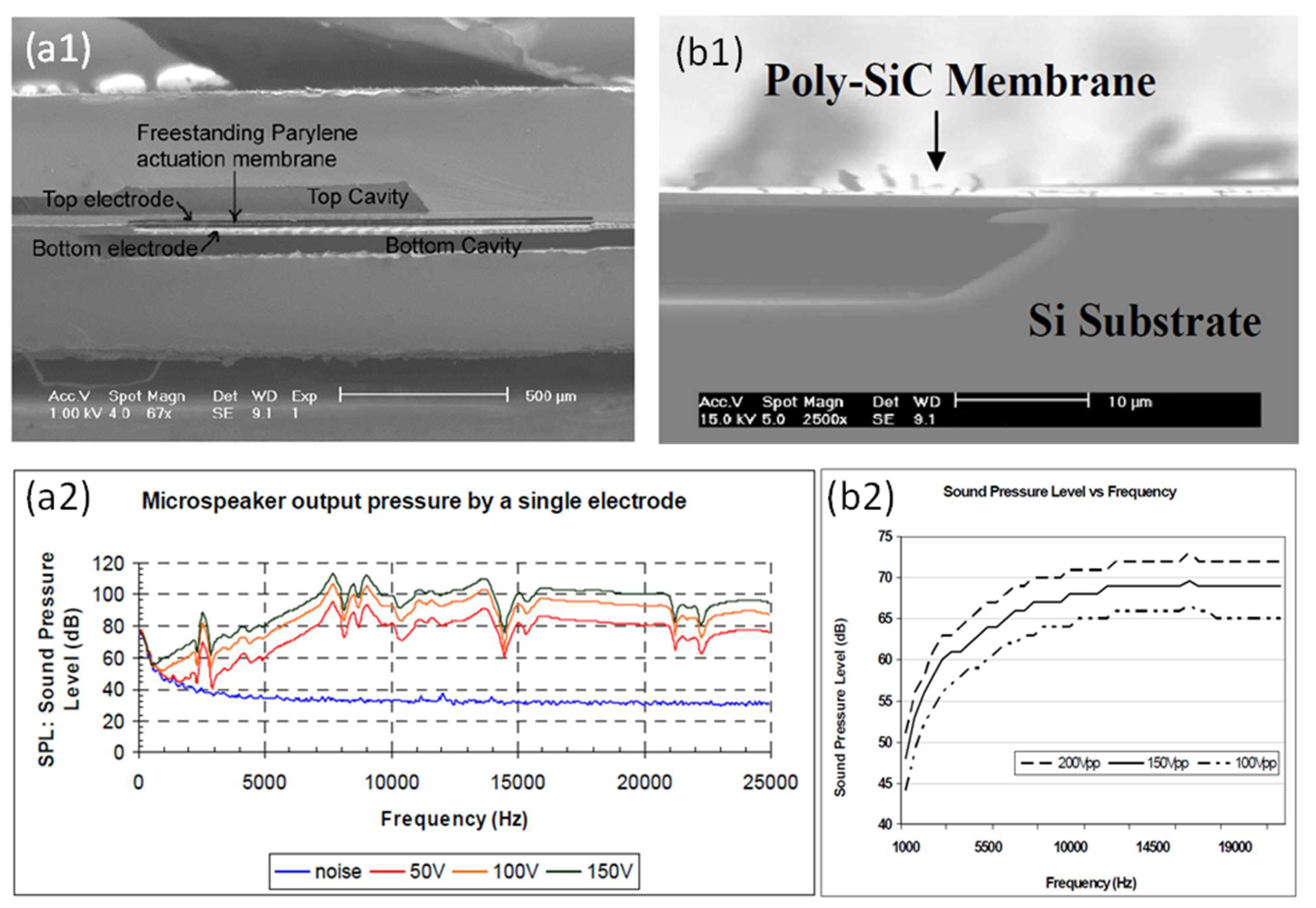
3.3.1. Devices with Different Diaphragm Materials
3.3.2. Approaches to Improve SPLs
3.4. Thermoacoustic MEMS Speakers
4. Comparison of Different MEMS Speakers
5. Summary and Outlook
Author Contributions
Funding
Data Availability Statement
Conflicts of Interest
References
- Hwang, S.-M.; Lee, H.-J.; Hong, K.-S.; Kang, B.-S.; Hwang, G.-Y. New development of combined permanent-magnet type microspeakers used for cellular phones. IEEE Trans. Magn. 2005, 41, 2000–2003. [Google Scholar] [CrossRef]
- Shahosseini, I.; Lefeuvre, E.; Moulin, J.; Martincic, E.; Woytasik, M.; Lemarquand, G. Optimization and microfabrication of high performance silicon-based MEMS microspeaker. IEEE Sens. J. 2013, 13, 273–284. [Google Scholar] [CrossRef]
- Shahosseini, I.; Lefeuve, E.; Mrtincic, E.; Woytasik, M.; Moulin, J.; Megherbi, S.; Ravaud, R.; Lemarquand, G. Microstructured silicon membrane with soft suspension beams for a high performance MEMS microspeaker. Microsyst. Technol. 2012, 18, 1791–1799. [Google Scholar] [CrossRef]
- Lee, C.-M.; Kwon, J.-H.; Kim, K.-S.; Park, J.-H.; Hwang, S.-M. Design and analysis of microspeakers to improve sound characteristics in a low frequency range. IEEE Trans. Magn. 2010, 46, 2048–2051. [Google Scholar] [CrossRef]
- Cheng, M.C.; Huang, W.S.; Huang, S.R.S. A silicon microspeaker for hearing instruments. J. Micromech. Microeng. 2004, 14, 859–866. [Google Scholar] [CrossRef]
- Lemarquand, G.; Ravaud, R.; Shahosseini, I.; Lemarquand, V.; Moulin, J.; Lefeuvre, E. MEMS electrodynamic loudspeakers for mobile phones. Appl. Acoust. 2012, 73, 379–385. [Google Scholar] [CrossRef]
- Je, S.S.; Rivas, F.; Diaz, R.E.; Kwon, J.; Kim, J.; Bakkaloglu, B.; Kiaei, S.; Fellow; Chae, J. A compact and low-cost MEMS loudspeaker for digital hearing aids. IEEE Trans. Biomed. Circuits Syst. 2009, 3, 348–358. [Google Scholar] [CrossRef]
- Roberts, R.C.; Du, J.; Ong, A.K.; Li, D.; Zorman, C.A.; Tien, N.C. Electrostatically driven touch-mode poly-SiC micro speaker. In Proceedings of the SENSORS, 2007 IEEE, Atlanta, GA, USA, 28–31 October 2007; pp. 284–287. [Google Scholar] [CrossRef]
- Kaiser, B.; Langa, S.; Ehrig, L.; Stolz, M.; Schenk, H.; Conrad, H.; Schenk, H.; Schimmanz, K.; Schuffenhauer, D. Concept and proof for an all-silicon MEMS micro speaker utilizing air chambers. Microsyst. Nanoeng. 2019, 5, 1–11. [Google Scholar] [CrossRef] [PubMed] [Green Version]
- Yi, S.H.; Kim, E.S. Micromachined piezoelectric microspeaker. Jpn. J. Appl. Phys. Part. 1 Regul. Pap. Short Notes Rev. Pap. 2005, 44, 3836–3841. [Google Scholar] [CrossRef]
- Cho, I.J.; Jang, S.; Nam, H.J. A Piezoelectrically actuated mems speaker with polyimide membrane and thin film Pb(Zr,Ti)O3(PZT) actuator. Integr. Ferroelectr. 2009, 105, 27–36. [Google Scholar] [CrossRef]
- Wang, H.; Li, M.; Yu, Y.; Chen, Z.; Ding, Y.; Jiang, H.; Xie, H. A piezoelectric MEMS loud speaker based on ceramic PZT. In Proceedings of the 2019 20th International Conference on Solid-State Sensors, Actuators and Microsystems & Eurosensors XXXIII (TRANSDUCERS & EUROSENSORS XXXIII), Berlin, Germany, 23–27 June 2019; IEEE: Piscataway, NJ, USA, 2019; pp. 857–860. [Google Scholar]
- Fei, W.; Zhou, J.; Guo, W. Low-voltage driven graphene foam thermoacoustic speaker. Small 2015, 11, 2252–2256. [Google Scholar] [CrossRef]
- Suk, J.W.; Kirk, K.; Hao, Y.; Hall, N.A.; Ruoff, R.S. Thermoacoustic sound generation from monolayer graphene for transparent and flexible sound sources. Adv. Mater. 2012, 24, 6342–6347. [Google Scholar] [CrossRef] [PubMed]
- Je, S.-S.; Wang, N.; Brown, H.C.; Arnold, D.P.; Chae, J. An electromagnetically actuated microspeaker with fully-integrated wax-bonded Nd-Fe-B micromagnets for hearing aid applications. In Proceedings of the TRANSDUCERS 2009—2009 International Solid-State Sensors, Actuators and Microsystems Conference, Denver, CO, USA, 21–25 June 2009; IEEE: Piscataway, NJ, USA, 2009; pp. 885–888. [Google Scholar]
- Wang, H.; Chen, Z.; Xie, H. A high-SPL piezoelectric MEMS loud speaker based on thin ceramic PZT. Sens. Actuators A Phys. 2020, 309, 112018. [Google Scholar] [CrossRef]
- Kim, H.J.; Koo, K.; Lee, S.Q.; Park, K.H.; Kim, J. High performance piezoelectric microspeakers and thin speaker array system. ETRI J. 2009, 31, 680–687. [Google Scholar] [CrossRef]
- Stoppel, F.; Mannchen, A.; Niekiel, F.; Beer, D.; Giese, T.; Wagner, B. New integrated full-range MEMS speaker for in-ear applications. In Proceedings of the 2018 IEEE Micro Electro Mechanical Systems (MEMS), Belfast, UK, 21–25 January 2018; IEEE: Piscataway, NJ, USA, 2018; pp. 1068–1071. [Google Scholar]
- Park, K.-H.; Jiang, Z.-X.; Hwang, S.-M. Design and Analysis of a Novel Microspeaker with Enhanced Low-Frequency SPL and Size Reduction. Appl. Sci. 2020, 10, 8902. [Google Scholar] [CrossRef]
- Liu, W.; Huang, J.; Shen, Y.; Cheng, J. Theoretical Modeling of Piezoelectric Cantilever MEMS Loudspeakers. Appl. Sci. 2021, 11, 6323. [Google Scholar] [CrossRef]
- Cheng, H.H.; Lo, S.C.; Huang, Z.R.; Wang, Y.J.; Wu, M.; Fang, W. On the design of piezoelectric MEMS microspeaker for the sound pressure level enhancement. Sens. Actuators A Phys. 2020, 306, 111960. [Google Scholar] [CrossRef]
- Stoppel, F.; Eisermann, C.; Gu-Stoppel, S.; Kaden, D.; Giese, T.; Wagner, B. Novel membrane-less two-way MEMS loudspeaker based on piezoelectric dual-concentric actuators. In Proceedings of the TRANSDUCERS 2017—19th International Conference on Solid-State Sensors, Actuators and Microsystems, Kaohsiung, Taiwan, 18–22 June 2017; IEEE: Piscataway, NJ, USA, 2017; pp. 2047–2050. [Google Scholar]
- Kim, H.J.; Yang, W.S. The effects of electrodes patterned onto the piezoelectric thin film on frequency response characteristics of PMN-PT MEMS acoustic actuators. J. Electroceramics 2015, 35, 45–52. [Google Scholar] [CrossRef]
- Wang, H.; Feng, P.X.L.; Xie, H. A dual-electrode MEMS speaker based on ceramic PZT with improved sound pressure level by phase tuning. In Proceedings of the 2021 IEEE 34th International Conference on Micro Electro Mechanical Systems (MEMS), Gainesville, FL, USA, 25–29 January 2021; IEEE: Piscataway, NJ, USA, 2021; Volume 2021, pp. 701–704. [Google Scholar]
- Usound GmbH. Available online: https://www.usound.com/home/ (accessed on 13 October 2021).
- TDK Corporation. Available online: https://www.tdk.com/en/news_center/press/20190521_01.html (accessed on 13 October 2021).
- Audio Pixels Limited. Available online: https://www.audiopixels.com.au/index.cfm/technology/ (accessed on 13 October 2021).
- Arioso Systems GmbH. Available online: https://arioso-systems.com/ (accessed on 13 October 2021).
- Chiang, H.-Y.; Huang, Y.-H. Vibration and sound radiation of an electrostatic speaker based on circular diaphragm. J. Acoust. Soc. Am. 2015, 137, 1714–1721. [Google Scholar] [CrossRef]
- Ŝvec, J.G.; Granqvist, S. Tutorial and guidelines on measurement of sound pressure level in voice and speech. J. Speech Lang. Hear. Res. 2018, 61, 441–461. [Google Scholar] [CrossRef]
- Fedtke, T.; Grason, L. Sound level calibration: Microphones, ear simulators, couplers, and sound level meters. Semin. Hear. 2014, 35, 295–311. [Google Scholar] [CrossRef]
- Jax, P.; Vary, P. Bandwidth extension of speech signals: A catalyst for the introduction of wideband speech coding? IEEE Commun. Mag. 2006, 44, 106–111. [Google Scholar] [CrossRef]
- Blevins, R.D. Formulas for Natural Frequency and Mode Shape; Van Nostrand Reinhold Company: New York, NY, USA, 1979; ISBN 9780442207106. [Google Scholar]
- Cheng, H.-H.; Huang, Z.-R.; Wu, M.; Fang, W. Low frequency sound pressure level improvement of piezoelectric MEMS microspeaker using novel spiral spring with dual electrode. In Proceedings of the 2019 20th International Conference on Solid-State Sensors, Actuators and Microsystems & Eurosensors XXXIII (TRANSDUCERS & EUROSENSORS XXXIII), Berlin, Germany, 23–27 June 2019; IEEE: Piscataway, NJ, USA, 2019; pp. 2013–2016. [Google Scholar]
- Yi, S.; Ur, S.C.; Kim, E.S. Performance of packaged piezoelectric microspeakers depending on the material properties. In Proceedings of the 2009 IEEE 22nd International Conference on Micro Electro Mechanical Systems, Sorrento, Italy, 25–29 January 2009; IEEE: Piscataway, NJ, USA, 2009; pp. 765–768. [Google Scholar]
- Seo, K.; Park, J.; Kim, H.; Kim, D.; Ur, S.; Yi, S. Micromachined piezoelectric microspeakers fabricated with high quality AlN thin film. Integr. Ferroelectr. 2007, 95, 74–82. [Google Scholar] [CrossRef]
- Sturtzer, E.; Shahosseini, I.; Pillonnet, G.; Lefeuvre, E.; Lemarquand, G. High fidelity microelectromechanical system electrodynamic micro-speaker characterization. J. Appl. Phys. 2013, 113, 214905. [Google Scholar] [CrossRef]
- Garud, M.V.; Pratap, R. A novel MEMS speaker with peripheral electrostatic actuation. J. Microelectromechanical Syst. 2020, 29, 592–599. [Google Scholar] [CrossRef]
- Zhou, Q.; Zettl, A. Electrostatic graphene loudspeaker. Appl. Phys. Lett. 2013, 102, 223109. [Google Scholar] [CrossRef] [Green Version]
- Melnikov, A.; Schenk, H.A.G.; Monsalve, J.M.; Wall, F.; Stolz, M.; Mrosk, A.; Langa, S.; Kaiser, B. Coulomb-actuated microbeams revisited: Experimental and numerical modal decomposition of the saddle-node bifurcation. Microsyst. Nanoeng. 2021, 7. [Google Scholar] [CrossRef]
- Younis, M.I.; Abdel-Rahman, E.M.; Nayfeh, A. A reduced-order model for electrically actuated microbeam-based MEMS. J. Microelectromechanical Syst. 2003, 12, 672–680. [Google Scholar] [CrossRef]
- Xiao, L.; Chen, Z.; Feng, C.; Liu, L.; Bai, Z.-Q.; Wang, Y.; Qian, L.; Zhang, Y.; Li, Q.; Jiang, K.; et al. Flexible, Stretchable, Transparent Carbon Nanotube Thin Film Loudspeakers. Nano Lett. 2008, 8, 4539–4545. [Google Scholar] [CrossRef]
- Neumann, J.J.; Gabriel, K.J. CMOS-MEMS membrane for audio-frequency acoustic actuation. Sens. Actuators A Phys. 2002, 95, 175–182. [Google Scholar] [CrossRef]
- Huang, J.H.; Her, H.-C.; Shiah, Y.C.; Shin, S.-J. Electroacoustic simulation and experiment on a miniature loudspeaker for cellular phones. J. Appl. Phys. 2008, 103, 033502. [Google Scholar] [CrossRef]
- Chang, J.R.; Wang, C.N. Acoustical analysis of enclosure design parameters for microspeaker system. J. Mech. 2019, 35, 1–12. [Google Scholar] [CrossRef]
- Blackstock, D.T. Fundamentals of Physical Acoustics; Wiley: New York, NY, USA, 2000. [Google Scholar]
- Chiang, H.-Y.; Huang, Y.-H. Experimental modeling and application of push-pull electrostatic speakers. J. Acoust. Soc. Am. 2019, 146, 2619–2631. [Google Scholar] [CrossRef] [PubMed]
- Spitz, B.; Wall, F.; Schenk, H.; Melnikov, A.; Pufe, W. Audio-transducer for in-ear-applications based on CMOS compatible electrostatic actuators. In Proceedings of the MikroSystemTechnik Kongress, Berlin, Germany, 28–30 October 2019. [Google Scholar]
- Sun, P.; Xu, D.P.; Hwang, S.M. Design of microspeaker module considering added stiffness. J. Mech. Sci. Technol. 2014, 28, 1623–1628. [Google Scholar] [CrossRef]
- Kim, B.H.; Lee, H.S.; Kim, S.W.; Kang, P.; Park, Y.S. Hydrodynamic responses of a piezoelectric driven MEMS inkjet print-head. Sens. Actuators A Phys. 2014, 210, 131–140. [Google Scholar] [CrossRef]
- Zhu, Y.; Liu, W.; Jia, K.; Liao, W.; Xie, H. A piezoelectric unimorph actuator based tip-tilt-piston micromirror with high fill factor and small tilt and lateral shift. Sens. Actuators A Phys. 2011, 167, 495–501. [Google Scholar] [CrossRef]
- Smith, G.L.; Rudy, R.Q.; Polcawich, R.G.; DeVoe, D.L. Integrated thin-film piezoelectric traveling wave ultrasonic motors. Sens. Actuators A Phys. 2012, 188, 305–311. [Google Scholar] [CrossRef]
- Rinaldi, M.; Zuniga, C.; Chengjie, Z.; Piazza, G. Super-high-frequency two-port AlN contour-mode resonators for RF applications. IEEE Trans. Ultrason. Ferroelectr. Freq. Control 2010, 57, 38–45. [Google Scholar] [CrossRef] [Green Version]
- Wang, H.; Yu, Y.; Chen, Z.; Yang, H.; Jiang, H.; Xie, H. Design and fabrication of a piezoelectric micromachined ultrasonic transducer array based on ceramic PZT. In Proceedings of the 2018 IEEE SENSORS, New Delhi, India, 28–31 October 2018; IEEE: Piscataway, NJ, USA, 2018; Volume 2018, pp. 1–4. [Google Scholar]
- Yi, S.; Yoon, M.; Ur, S. Piezoelectric microspeakers with high compressive ZnO film and floating electrode. J. Electroceramics 2009, 23, 295–300. [Google Scholar] [CrossRef]
- Tseng, S.-H.; Lo, S.-C.; Wang, Y.-J.; Lin, S.-W.; Wu, M.; Fang, W. Sound pressure and low frequency enhancement using novel PZT MEMS microspeaker design. In Proceedings of the 2020 IEEE 33rd International Conference on Micro Electro Mechanical Systems (MEMS), Vancouver, BC, Canada, 18–22 January 2020; IEEE: Piscataway, NJ, USA, 2020; Volume 2020, pp. 546–549. [Google Scholar]
- Ren, T.; Zhang, L.; Liu, L.; Li, Z. Design optimization of beam-like ferroelectrics-silicon microphone and microspeaker. IEEE Trans. Ultrason. Ferroelectr. Freq. Control 2002, 49, 266–270. [Google Scholar] [CrossRef]
- Lee, S.S.; Ried, R.P.; White, R.M. Piezoelectric cantilever microphone and microspeaker. J. Microelectromechanical Syst. 1996, 5, 238–242. [Google Scholar] [CrossRef]
- Wang, H.; Godara, M.; Chen, Z.; Xie, H. A one-step residue-free wet etching process of ceramic PZT for piezoelectric transducers. Sens. Actuators A Phys. 2019, 290, 130–136. [Google Scholar] [CrossRef] [PubMed]
- Jung, J.K.; Lee, W.J. Dry etching characteristics of Pb(Zr,Ti)O3 films in CF4 and Cl2/CF4 inductively coupled plasmas. Jpn. J. Appl. Phys. Part. 1 Regul. Pap. Short Notes Rev. Pap. 2001, 40, 1408–1419. [Google Scholar] [CrossRef]
- Shung, K.K.; Cannata, J.M.; Zhou, Q.F. Piezoelectric materials for high frequency medical imaging applications: A review. J. Electroceramics 2007, 19, 139–145. [Google Scholar] [CrossRef]
- Muralt, P. Recent progress in materials issues for piezoelectric MEMS. J. Am. Ceram. Soc. 2008, 91, 1385–1396. [Google Scholar] [CrossRef]
- Muralt, P. PZT thin films for microsensors and actuators: Where do we stand? IEEE Trans. Ultrason. Ferroelectr. Freq. Control 2000, 47, 903–915. [Google Scholar] [CrossRef]
- Ko, S.C.; Kim, Y.C.; Lee, S.S.; Choi, S.H.; Kim, S.R. Micromachined piezoelectric membrane acoustic device. Sens. Actuators A Phys. 2003, 103, 130–134. [Google Scholar] [CrossRef]
- Shelton, S.; Chan, M.L.; Park, H.; Horsley, D.; Boser, B.; Izyumin, I.; Przybyla, R.; Frey, T.; Judy, M.; Nunan, K.; et al. CMOS-compatible AlN piezoelectric micromachined ultrasonic transducers. In Proceedings of the IEEE International Ultrasonics Symposium, Rome, Italy, 20–23 September 2009; pp. 402–405. [Google Scholar] [CrossRef]
- Ait Aissa, K.; Achour, A.; Camus, J.; Le Brizoual, L.; Jouan, P.-Y.; Djouadi, M.-A. Comparison of the structural properties and residual stress of AlN films deposited by dc magnetron sputtering and high power impulse magnetron sputtering at different working pressures. Thin Solid Films 2014, 550, 264–267. [Google Scholar] [CrossRef]
- Ababneh, A.; Schmid, U.; Hernando, J.; Sánchez-Rojas, J.L.; Seidel, H. The influence of sputter deposition parameters on piezoelectric and mechanical properties of AlN thin films. Mater. Sci. Eng. B 2010, 172, 253–258. [Google Scholar] [CrossRef]
- Lim, W.T.; Lee, C.H. Highly oriented ZnO thin films deposited on Ru/Si substrates. Thin Solid Film. 1999, 353, 12–15. [Google Scholar] [CrossRef]
- Han, C.-H.; Kim, E.S. Parylene-diaphragm piezoelectric acoustic transducers. In Proceedings of the Proceedings IEEE Thirteenth Annual International Conference on Micro Electro Mechanical Systems, Miyazaki, Japan, 23–27 January 2000; IEEE: Piscataway, NJ, USA, 2000; pp. 148–152. [Google Scholar]
- Zhang, Y.; Du, G.; Liu, D.; Wang, X.; Ma, Y.; Wang, J.; Yin, J.; Yang, X.; Hou, X.; Yang, S. Crystal growth of undoped ZnO films on Si substrates under different sputtering conditions. J. Cryst. Growth 2002, 243, 439–443. [Google Scholar] [CrossRef]
- CTS Incorporation. Available online: https://www.ctscorp.com/products/piezoelectric-move-products/speakers/ (accessed on 13 October 2021).
- Li, J.; Wang, C.; Ren, W.; Ma, J. ZnO thin film piezoelectric micromachined microphone with symmetric composite vibrating diaphragm. Smart Mater. Struct. 2017, 26, 55033. [Google Scholar] [CrossRef]
- Watanabe, S.; Fujiu, T.; Fujii, T. Effect of poling on piezoelectric properties of lead zirconate titanate thin films formed by sputtering. Appl. Phys. Lett. 1995, 66, 1481–1483. [Google Scholar] [CrossRef]
- Cheng, J.-R.; Zhu, W.; Li, N.; Cross, L.E. Electrical properties of sol-gel-derived Pb(Zr0.52Ti0.48)O3 thin films on a PbTiO3-coated stainless steel substrate. Appl. Phys. Lett. 2002, 81, 4805–4807. [Google Scholar] [CrossRef]
- Tsaur, J.; Wang, Z.J.; Zhang, L.; Ichiki, M.; Wan, J.W.; Maeda, R. Preparation and application of lead zirconate titanate (PZT) films deposited by hybrid process: Sol-gel method and laser ablation. Jpn. J. Appl. Phys. Part. 1 Regul. Pap. Short Notes Rev. Pap. 2002, 41, 6664–6668. [Google Scholar] [CrossRef]
- Moriyama, M.; Totsu, K.; Tanaka, S. Sol–gel deposition and characterization of lead zirconate titanate thin film using different commercial sols. Sens. Mater. 2019, 31, 2497–2509. [Google Scholar] [CrossRef]
- Gao, R.; Chu, X.; Huan, Y.; Sun, Y.; Liu, J.; Wang, X.; Li, L. A study on (K, Na) NbO3 based multilayer piezoelectric ceramics micro speaker. Smart Mater. Struct. 2014, 23, 105018. [Google Scholar] [CrossRef]
- Wang, Q.; Yi, Z.; Ruan, T.; Xu, Q.; Yang, B.; Liu, J. Obtaining high SPL piezoelectric MEMS speaker via a rigid-flexible vibration coupling mechanism. J. Microelectromechanical Syst. 2021, 30, 725–732. [Google Scholar] [CrossRef]
- Wang, Y.-J.; Lo, S.; Hsieh, M.; Wang, S.; Chen, Y.; Wu, M.; Fang, W. Multi-way in-phase/out-of-phase driving cantilever array for performance enhancement of PZT MEMS microspeaker. In Proceedings of the 2021 IEEE 34th International Conference on Micro Electro Mechanical Systems (MEMS), Gainesville, FL, USA, 25–29 January 2021; IEEE: Piscataway, NJ, USA, 2021; pp. 83–84. [Google Scholar]
- Diamond, B.M.; Neumann, J.J.; Gabriel, K.J. Digital sound reconstruction using arrays of CMOS-MEMS microspeakers. In Proceedings of the Technical Digest. MEMS 2002 IEEE International Conference on Micro Electro Mechanical Systems, Las Vegas, NV, USA, 24 January 2002; IEEE: Piscataway, NJ, USA, 2002; Volume 1, pp. 292–295. [Google Scholar]
- Casset, F.; Dejaeger, R.; Laroche, B.; Desloges, B.; Leclere, Q.; Morisson, R.; Bohard, Y.; Goglio, J.P.; Escato, J.; Fanget, S. A 256 MEMS Membrane Digital Loudspeaker Array Based on PZT Actuators. Procedia Eng. 2015, 120, 49–52. [Google Scholar] [CrossRef]
- Arevalo, A.; Conchouso, D.; Castro, D.; Kosel, J.; Foulds, I.G. Piezoelectric transducer array microspeaker. In Proceedings of the IEEE 11th Annual International Conference on Nano/Micro Engineered and Molecular Systems (NEMS), Sendai, Japan, 17–20 April 2016; pp. 180–183. [Google Scholar] [CrossRef]
- Chen, Y.C.; Liu, W.T.; Chao, T.Y.; Cheng, Y.T. An optimized Cu-Ni nanocomposite coil for low-power electromagnetic microspeaker fabrication. In Proceedings of the TRANSDUCERS 2009—2009 International Solid-State Sensors, Actuators and Microsystems Conference, Denver, CO, USA, 21–25 June 2009; pp. 25–28. [Google Scholar] [CrossRef]
- Shahosseini, I.; Lefeuvre, E.; Moulin, J.; Woytasik, M.; Martincic, E.; Pillonnet, G.; Lemarquand, G. Electromagnetic MEMS microspeaker for portable electronic devices. Microsyst. Technol. 2013, 19, 879–886. [Google Scholar] [CrossRef] [Green Version]
- Majlis, B.Y.; Sugandi, G.; Noor, M.M. Compact electrodynamics MEMS-speaker. In Proceedings of the 2017 China Semiconductor Technology International Conference (CSTIC), Shanghai, China, 12–13 March 2017; IEEE: Piscataway, NJ, USA, 2017; pp. 1–3. [Google Scholar]
- Chen, Y.C.; Cheng, Y.T. A low-power milliwatt electromagnetic microspeaker using a PDMS membrane for hearing aids application. In Proceedings of the IEEE 24th International Conference on Micro Electro Mechanical Systems, Cancun, Mexico, 23–27 January 2011; pp. 1213–1216. [Google Scholar] [CrossRef]
- Murarka, A.; Lang, J.H.; Bulovic, V. Printed membrane electrostatic MEMS microspeakers. In Proceedings of the IEEE 29th International Conference on Micro Electro Mechanical Systems (MEMS), Shanghai, China, 24–28 January 2016; pp. 1118–1121. [Google Scholar] [CrossRef]
- Kim, H.; Astle, A.A.; Najafi, K.; Bernal, L.P.; Washabaugh, P.D.; Cheng, F. Bi-directional electrostatic micro speaker with two large-deflection flexible membranes actuated by single/dual electrodes. In Proceedings of the SENSORS, 2005 IEEE, Irvine, CA, USA, 30 October–3 November 2005; pp. 89–92. [Google Scholar] [CrossRef]
- Bao, M.; Yang, H. Squeeze film air damping in MEMS. Sens. Actuators A Phys. 2007, 136, 3–27. [Google Scholar] [CrossRef]
- Glacer, C.; Dehé, A.; Tumpold, D.; Laur, R. Silicon microspeaker with out-of-plane displacement. In Proceedings of the IEEE International Conference on Nano/micro Engineered & Molecular Systems, Waikiki Beach, HI, USA, 13–16 April 2014. [Google Scholar]
- Arevalo, A.; Castro, D.; Conchouso, D.; Kosel, J.; Foulds, I.G. Digital electrostatic acoustic transducer array. In Proceedings of the IEEE 11th Annual International Conference on Nano/Micro Engineered and Molecular Systems (NEMS), Sendai, Japan, 17–20 April 2016; pp. 225–228. [Google Scholar] [CrossRef]
- Sano, C.; Ataka, M.; Hashiguchi, G.; Toshiyoshi, H. An electret-augmented low-voltage MEMS electrostatic out-of-plane actuator for acoustic transducer applications. Micromachines 2020, 11, 267. [Google Scholar] [CrossRef] [PubMed] [Green Version]
- Conrad, H.; Schenk, H.; Kaiser, B.; Langa, S.; Gaudet, M.; Schimmanz, K.; Stolz, M.; Lenz, M. A small-gap electrostatic micro-actuator for large deflections. Nat. Commun. 2015, 6, 10078. [Google Scholar] [CrossRef] [PubMed]
- Tian, H.; Ren, T.-L.; Xie, D.; Wang, Y.-F.; Zhou, C.-J.; Feng, T.-T.; Fu, D.; Yang, Y.; Peng, P.-G.; Wang, L.-G.; et al. Graphene-on-paper sound source devices. ACS Nano 2011, 5, 4878–4885. [Google Scholar] [CrossRef] [PubMed]
- Wang, D.; He, X.; Zhao, J.; Jin, L.; Ji, X. Research on the electrical-thermal-acoustic conversion behavior of thermoacoustic speakers based on multilayer graphene film. IEEE Sens. J. 2020, 20, 14646–14654. [Google Scholar] [CrossRef]





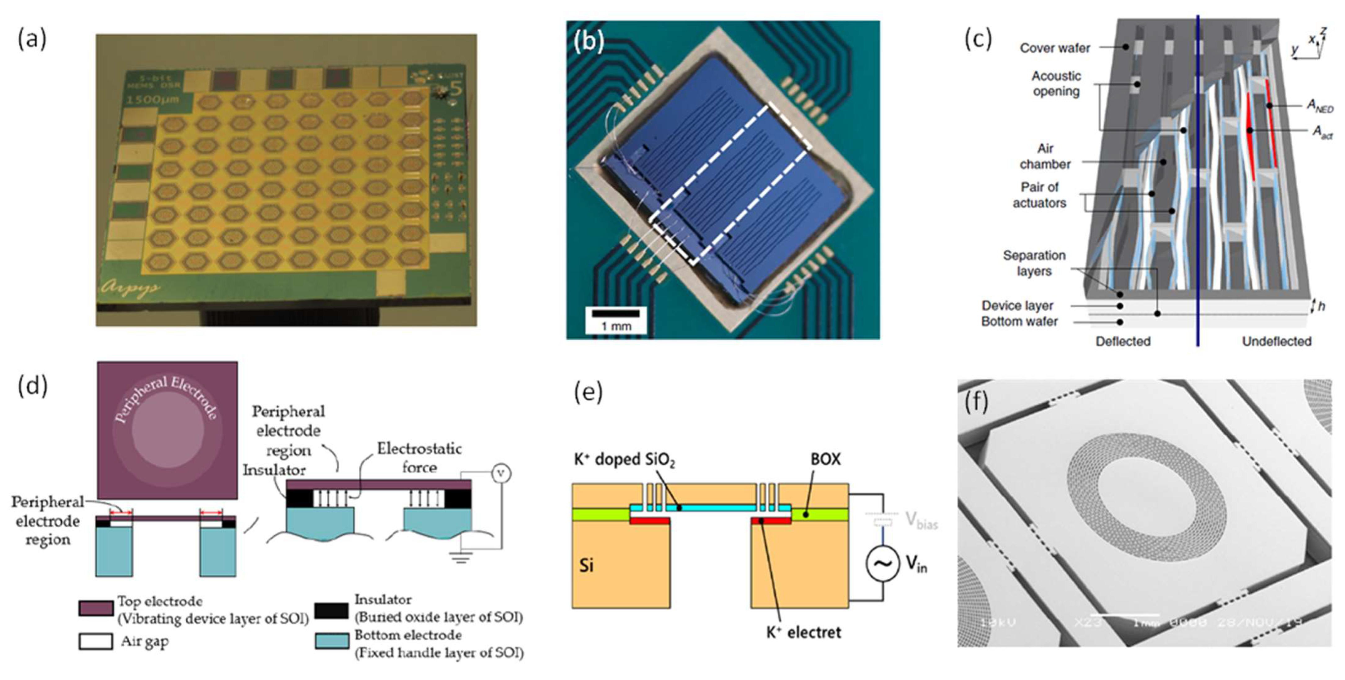
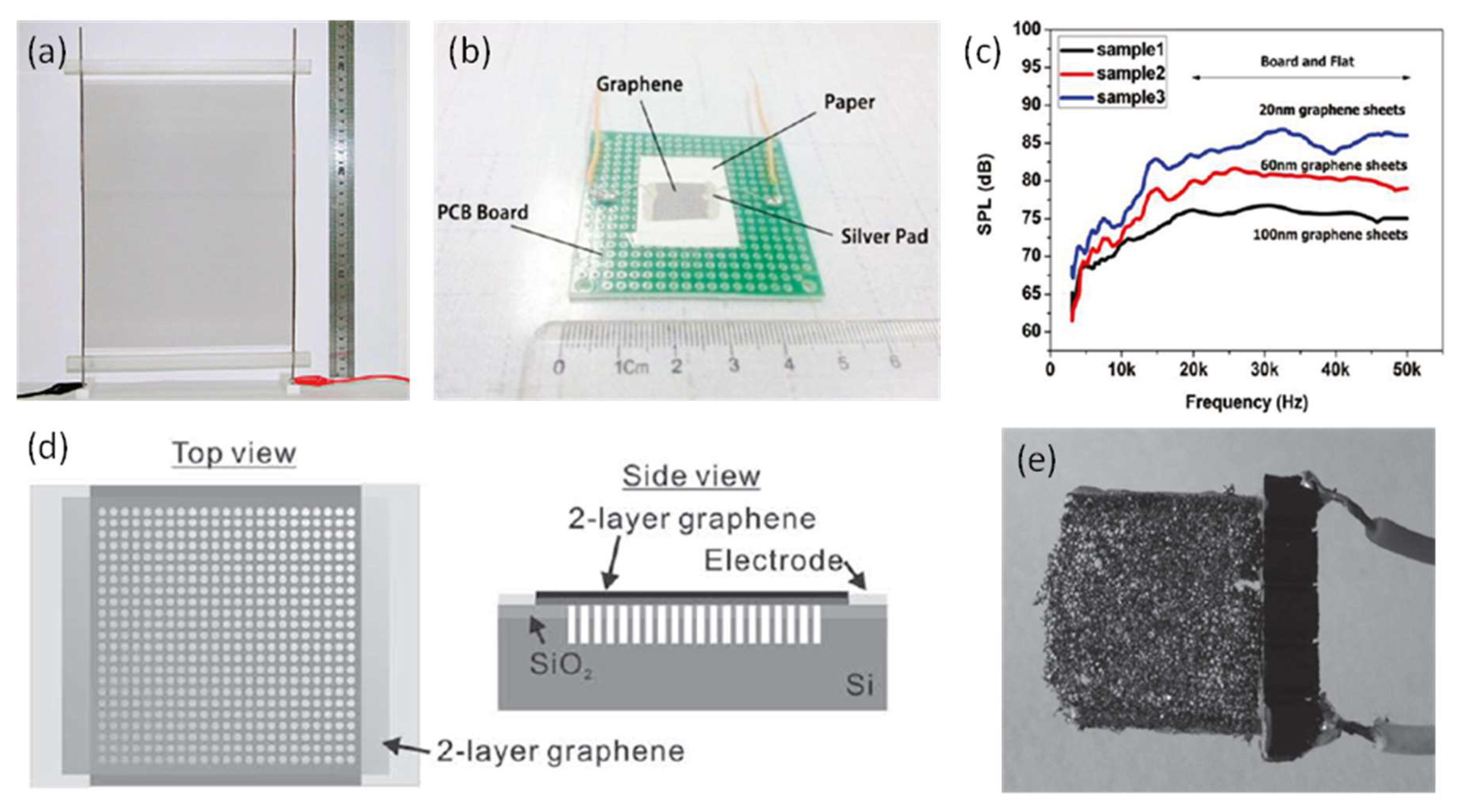
| Property | ZnO | AlN | Sol-Gel PZT | Sputtered PZT | Ceramic PZT-5H |
|---|---|---|---|---|---|
| Density (kg/m3) | 5700 | 3260 | 7700 | 7700 | 7800 |
| Young’s modulus (GPa) | 98.6 | 283 | 96 | 96 | 50 |
| Dielectric constant | 8.8 | 8.5–10.7 | 650–1470 | 400–980 | 3400 |
| Piezoelectric constant d31 (pm/V) | 3.9–5.5 | 2–2.6 | 23–76 | 45–102 | 270–300 |
| Ref. | Piezoelectric Layer | Diaphragm Size | 1st Resonant Frequency | Maximum SPL | Driving Voltage | Note | |
|---|---|---|---|---|---|---|---|
| In-coupler measurement | [58] | 0.5 μm ZnO | 2 mm length (square) | 890 Hz | 100 dB at 4.8 kHz | 12 Vpp | Measured into a 2 cm3 coupler |
| [21] | 1 μm sputtered PZT | 1.13 mm diameter (central part) | 1.85 kHz | 90.1 dB at 1.85 kHz | 2 Vpp | Measured in a 3-cm-long tube | |
| [78] | 1 μm sputtered PZT | 2 mm side length (hexagon) | 6.7 kHz | 101.2 dB at 6.7 kHz | 2V (unspecified) | Measured in an ear simulator | |
| [79] | 2 μm sputtered PZT | 4 mm2 (rectangle) | 1.54 kHz | 110 dB at 1.54 kHz | 2 Vpp | Measured in an ear simulator | |
| [56] | 2 μm sputtered PZT | 3.24 mm2 (four triangles) | ~6 kHz | 118.1 dB at 11.9 kHz | 2 Vpp | 5-speaker array, measured in an ear simulator | |
| [18] | 2 μm sputtered PZT | 4 mm length (square) | 8.3 kHz | 138 dB at 8.3 kHz | 2 Vpp | Measured in an ear simulator | |
| Free-field measurement | [64] | 0.5 μm ZnO | 3 mm length (square) | 7.3 kHz | 83.1 dB at 13.3 kHz | 30 Vpp | Measured at 1 cm |
| [10] | 0.5 μm ZnO | 5 mm length (square) | 2.92 kHz | 92.4 dB at 2.92 kHz | 6 Vpp | Measured at 2 mm | |
| [36] | 0.5 μm AlN | 4 mm length (square) | − | 100 dB at 10 kHz | 20 Vpp | Measured at 3 mm | |
| [35] | 0.5 μm AlN | − | − | 104 dB at 3 kHz | 20 Vpp | Device in a 4 cm3 package, measured at 1 cm | |
| [11] | 0.7 μm sol-gel PZT | 2 mm diameter | − | 90 dB at 10 kHz | 13 V (unspecified) | Measured at 1 cm | |
| [81] | 2 μm sol-gel PZT | 2.6 mm diameter | 18 kHz | ~110 dB | 8 V (unspecified) | 256-speaker array, measured at 13 cm | |
| [16] | 5 μm ceramic PZT | 6 mm diameter | 4.3 kHz | 119 dB at 9 kHz | 10 Vpp | Measured at 1 cm | |
| [17] | 40 μm ceramic PZT | 18 mm × 20 mm | 0.49 kHz | ~106 dB at 5.5 kHz | 32 Vpp | Measured at 1 cm | |
| [23] | 10 μm PMN-PT | 8.5 mm diameter | 1.4–1.84 kHz | ~100 dB at 6.5 kHz | 10 Vpp | Measured at 1 cm |
| Ref | Diaphragm Material | Diaphragm Size | Maximum SPL | Power Consumption | Note |
|---|---|---|---|---|---|
| [5] | Polyimide | 3.5 mm diameter | 93 dB at 5 kHz | 320 mW | Measured in a 2 cm3 volume |
| [7] | Polyimide | 3 mm diameter | 106 dB at 1 kHz | 0.13 mW | Calculated based on the displacement |
| [85] | Polyimide | 2.5 mm diameter | 90 dB at 1,5,10 kHz | − | Measured in a sealed 1500 mm3 silicone tube |
| [83] | SU-8 | - | Around 85 dB at 5.2 kHz | − | Measured in a 2 cm3 volume |
| [86] | PDMS | 3.5 mm diameter | 106 dB at 1 kHz | 1.76 mW | Measured in a 2 cm3 volume |
| [2] | Silicon | 15 mm diameter | 80 dB at 0. 33 kHz | 0.5 W | Measured at 10 cm |
| Ref | Diaphragm Size | Electrode Separation | Maximum SPL | Driving Voltage | Note |
|---|---|---|---|---|---|
| [92] | 2 mm diameter | 2 μm, peripheral electrode | 50 dB at around 35 kHz | AC 5 Vpp | Measured at 1.5 cm |
| [8] | 0.8 mm diameter | 8 μm, touch mode | 73 dB at 16.59 kHz | AC 200 Vpp | Measured at 1 cm |
| [38] | 3.1 mm diameter | 1 μm, peripheral electrode | 75–78 dB at above 10 kHz | DC 30 V + AC 30 V | Measured at 1 cm |
| [88] | 2 mm length (square) | 7.5 μm | 113.4 dB at 7.68 kHz | AC 150 V | Measured at 1 cm |
| [9] | - | - | 104 dB at 11.4 kHz | DC 40 V + AC 10 Vpp | Measured in an ear simulator |
Publisher’s Note: MDPI stays neutral with regard to jurisdictional claims in published maps and institutional affiliations. |
© 2021 by the authors. Licensee MDPI, Basel, Switzerland. This article is an open access article distributed under the terms and conditions of the Creative Commons Attribution (CC BY) license (https://creativecommons.org/licenses/by/4.0/).
Share and Cite
Wang, H.; Ma, Y.; Zheng, Q.; Cao, K.; Lu, Y.; Xie, H. Review of Recent Development of MEMS Speakers. Micromachines 2021, 12, 1257. https://doi.org/10.3390/mi12101257
Wang H, Ma Y, Zheng Q, Cao K, Lu Y, Xie H. Review of Recent Development of MEMS Speakers. Micromachines. 2021; 12(10):1257. https://doi.org/10.3390/mi12101257
Chicago/Turabian StyleWang, Haoran, Yifei Ma, Qincheng Zheng, Ke Cao, Yao Lu, and Huikai Xie. 2021. "Review of Recent Development of MEMS Speakers" Micromachines 12, no. 10: 1257. https://doi.org/10.3390/mi12101257
APA StyleWang, H., Ma, Y., Zheng, Q., Cao, K., Lu, Y., & Xie, H. (2021). Review of Recent Development of MEMS Speakers. Micromachines, 12(10), 1257. https://doi.org/10.3390/mi12101257


