
Total Harmonic Distortion of a Piezoelectric MEMS Loudspeaker in an IEC 60318-4 Coupler Estimation Using Static Measurements and a Nonlinear State Space Model

 , ,
, ,
Abstract
:1. Introduction
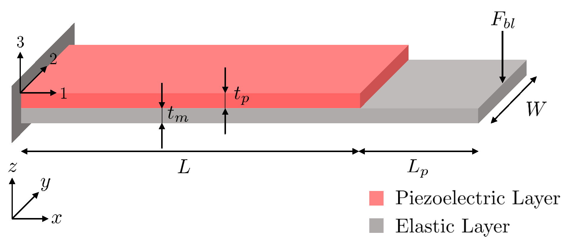
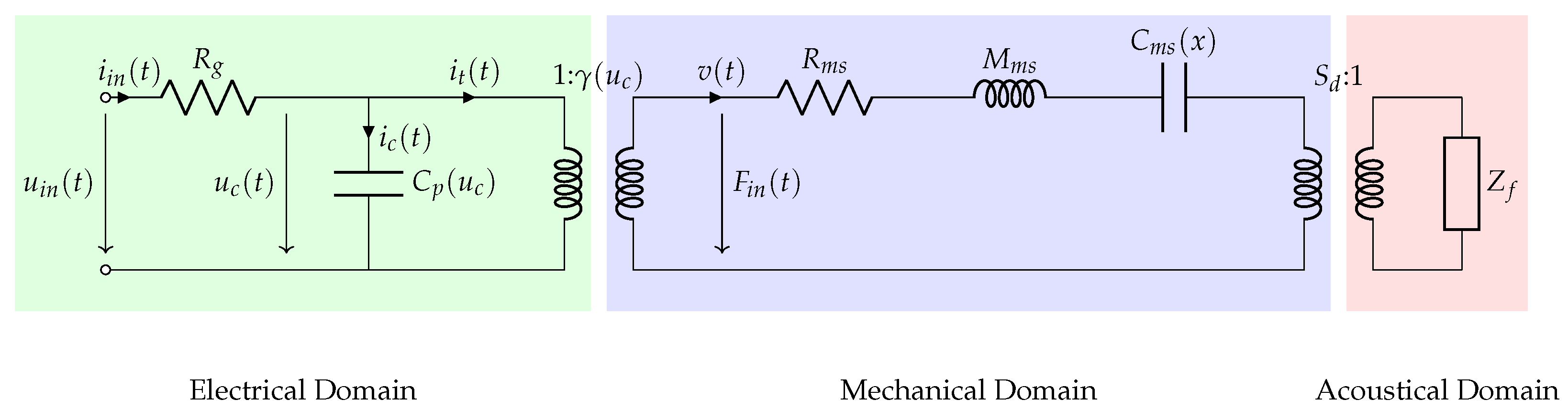
2. Nonlinear State Space Model
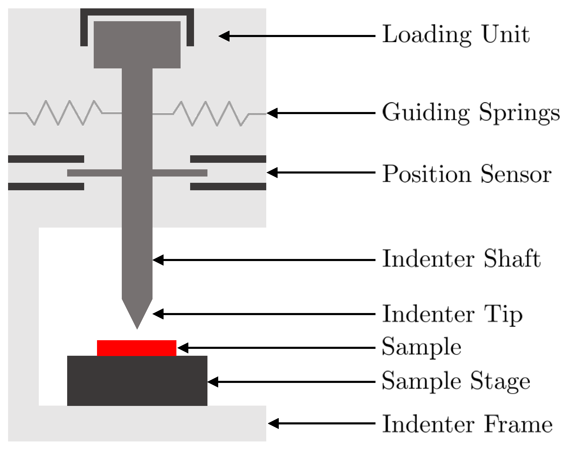
3. Static Measurements
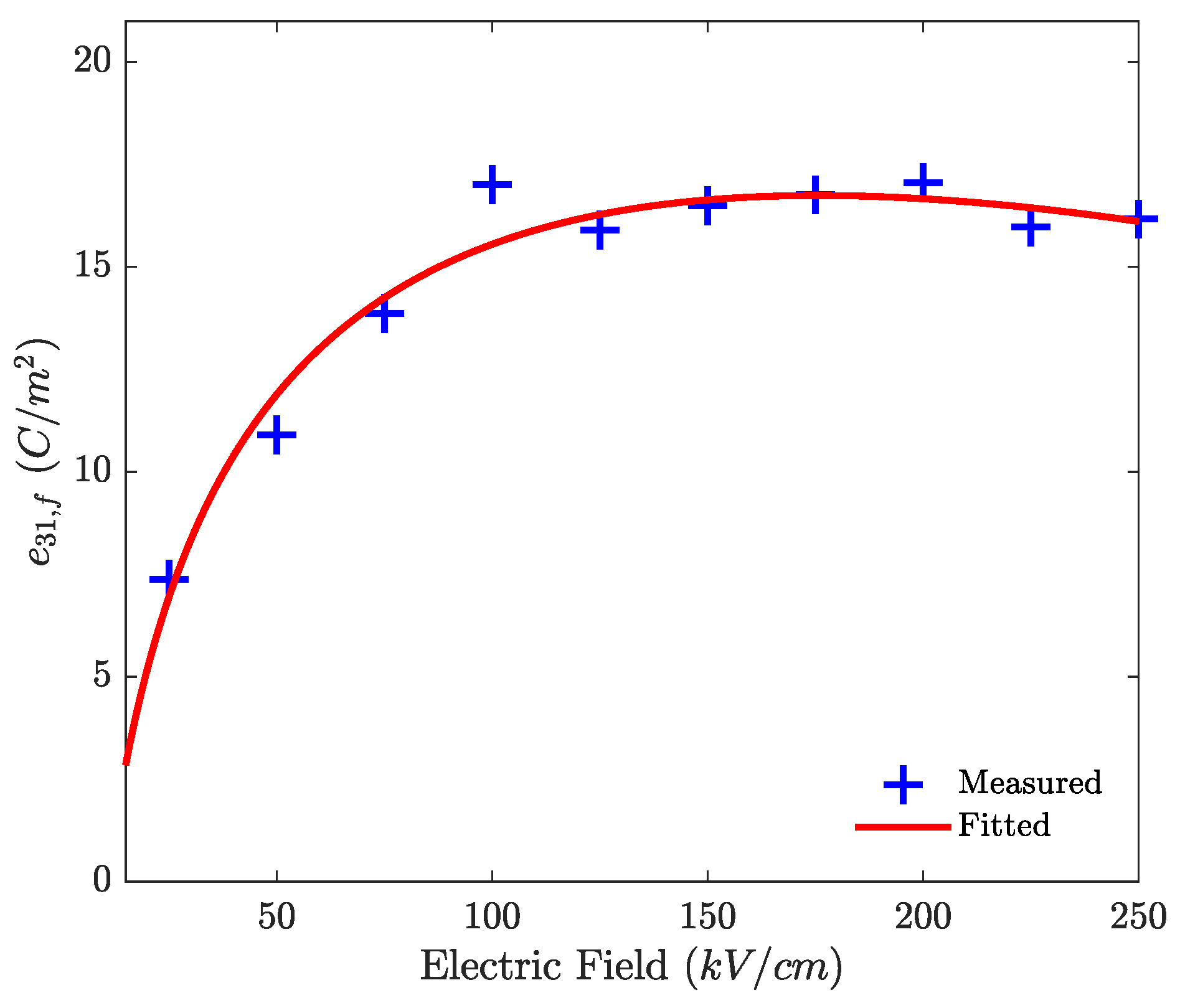
3.1. Nonlinear Electromechanical Function
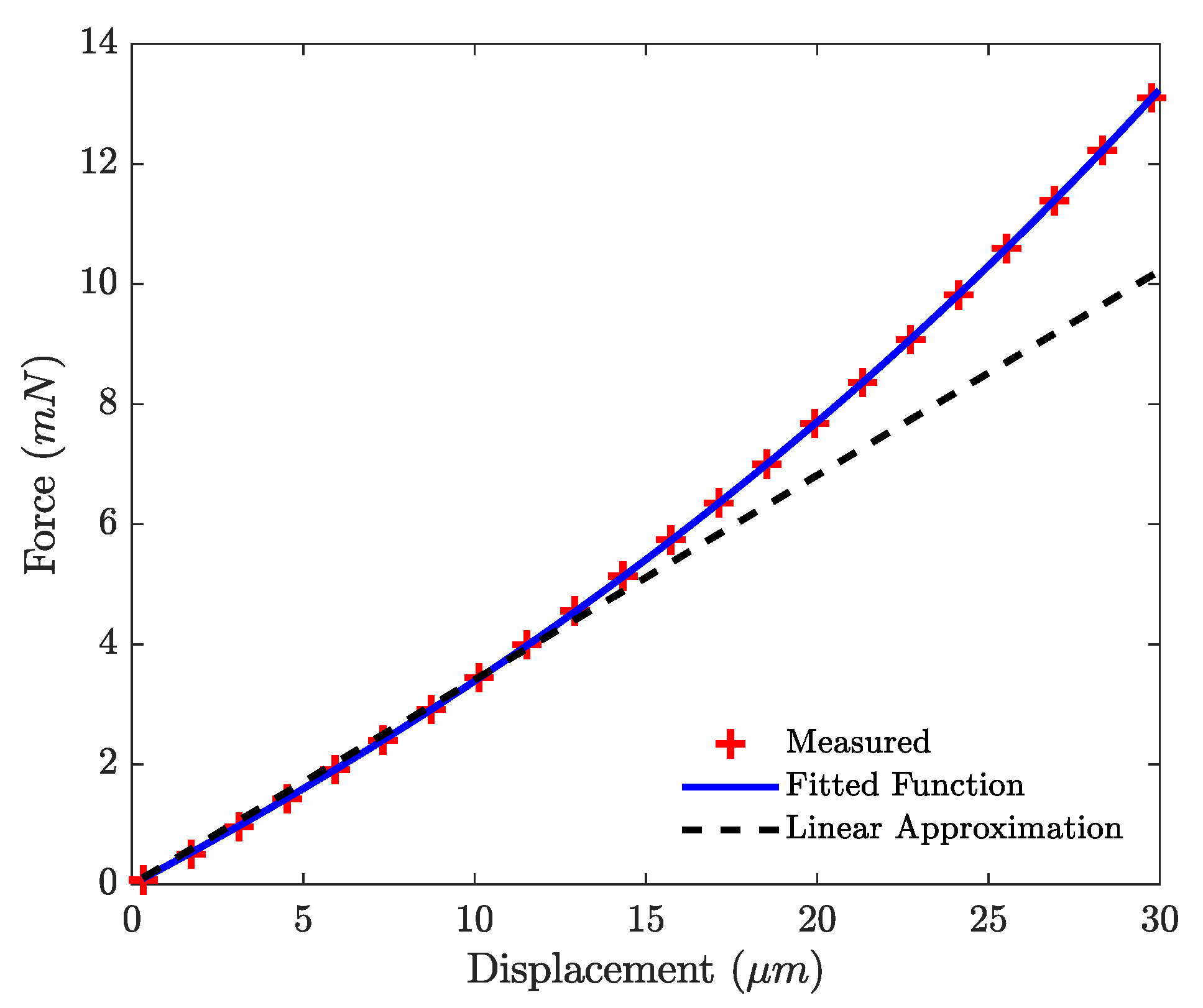
3.2. Nonlinear Stiffness
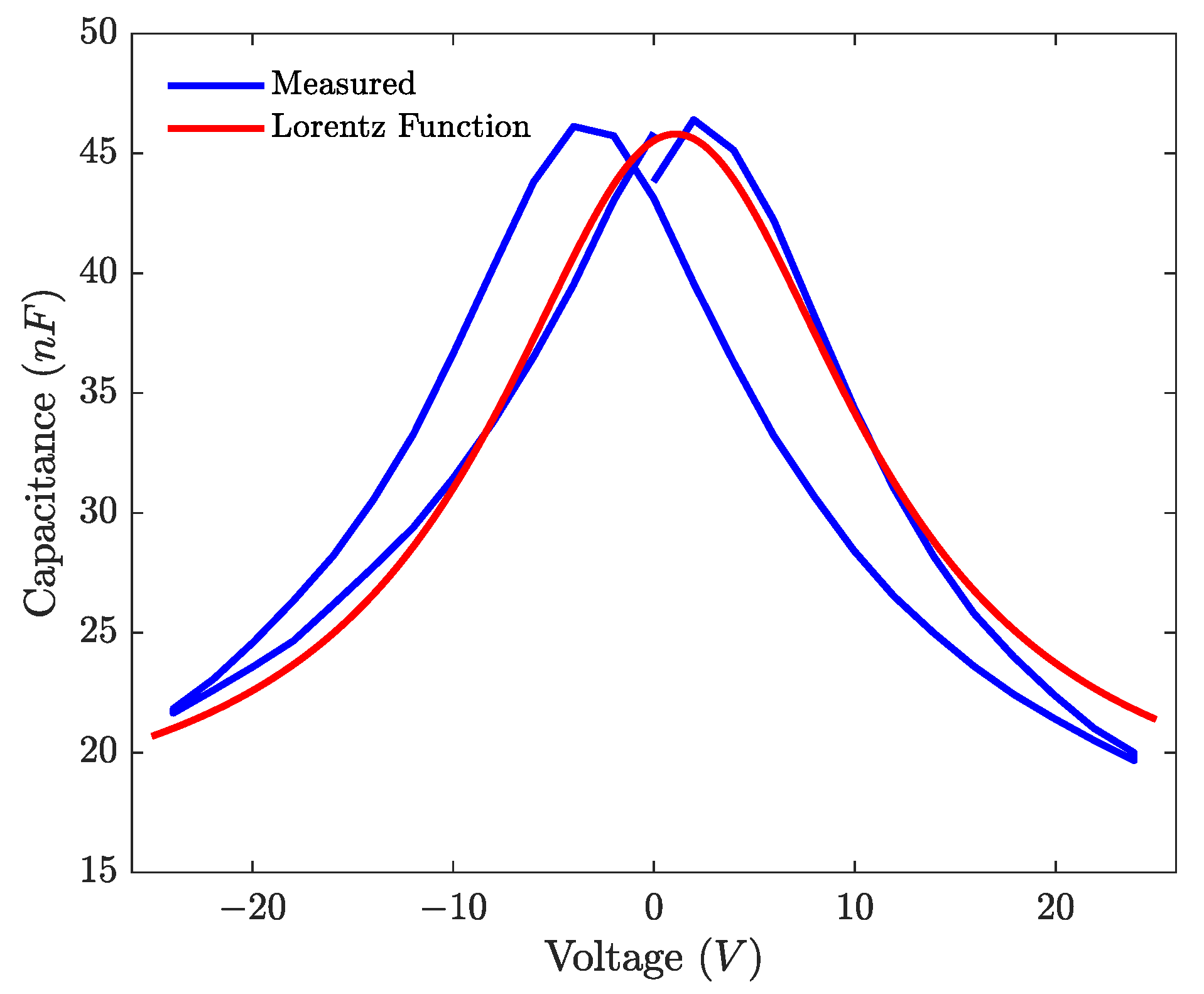
3.3. Capacitance
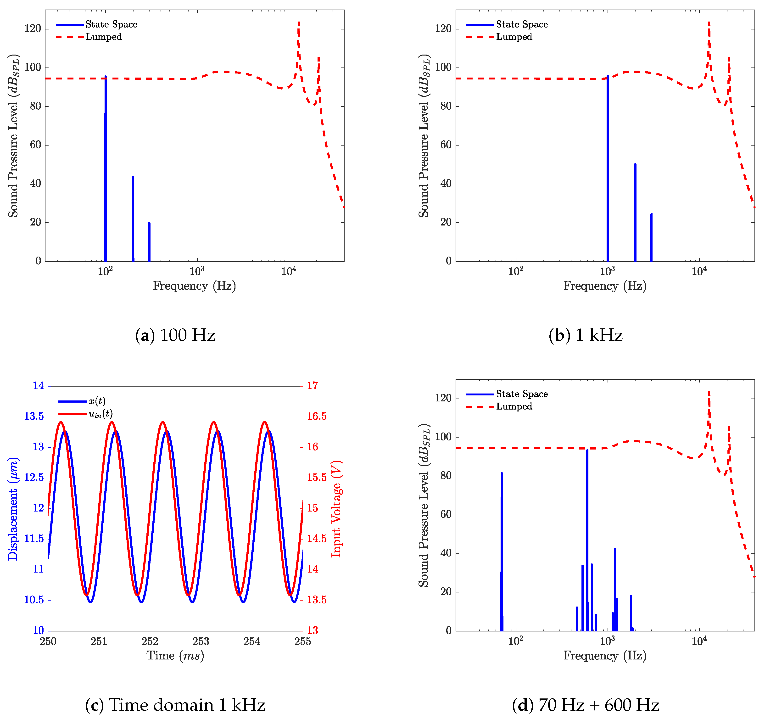
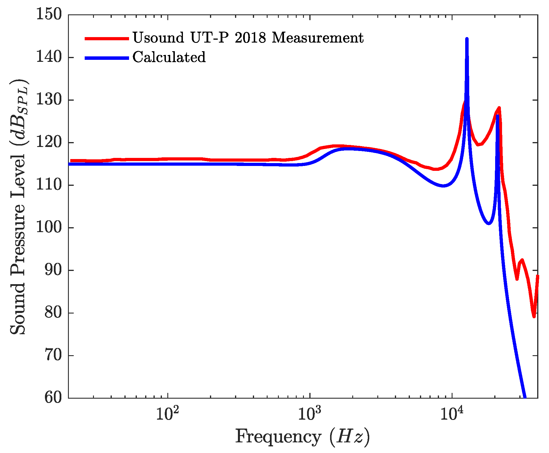
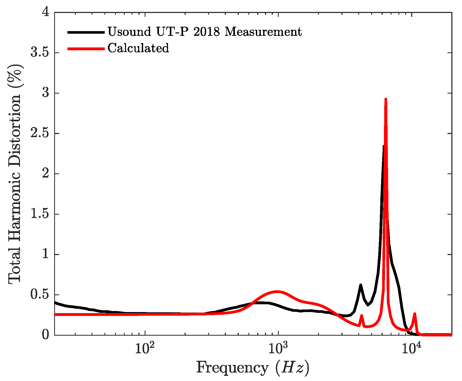
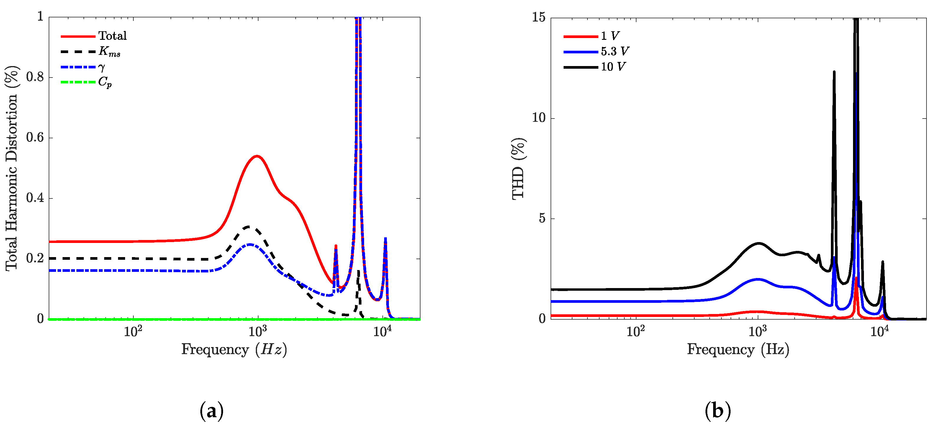
4. Results
5. Conclusions
Author Contributions
Funding
Institutional Review Board Statement
Informed Consent Statement
Conflicts of Interest
Abbreviations
| THD | Total Harmonic Distortion |
| MEMS | Micro Electromechanical Systems |
| IEC | International Electrotechnical Commission |
| DUT | Device Under Test |
| DBLI | Double-Beam Laser Interferometer |
| PZT | Lead Zirconate Titanate |
Appendix A. State Space Equations
References
- Shahosseini, I.; Lefeuvre, E.; Moulin, J.; Martincic, E.; Woytasik, M.; Lemarquand, G. Optimization and Microfabrication of High Performance Silicon-Based MEMS Microspeaker. IEEE Sens. J. 2013, 13, 273–284. [Google Scholar] [CrossRef]
- Shahosseini, I. Vers des Micro-Haut-Parleurs à Hautes Performances Électroacoustiques en Technologie Silicium. Ph.D. Thesis, Université Paris Sud, Paris, France, 2012; p. 206. [Google Scholar]
- Wang, H.; Feng, P.X.L.; Xie, H. A Dual-Electrode MEMS Speaker Based on Ceramic PZT with Improved Sound Pressure Level by Phase Tuning. In Proceedings of the 2021 IEEE 34th International Conference on Micro Electro Mechanical Systems (MEMS), Gainesville, FL, USA, 25–29 January 2021; pp. 701–704. [Google Scholar] [CrossRef]
- Wang, Q.; Yi, Z.; Ruan, T.; Xu, Q.; Yang, B.; Liu, J. Obtaining High SPL Piezoelectric MEMS Speaker via a Rigid-Flexible Vibration Coupling Mechanism. J. Microelectromech. Syst. 2021, 30, 725–732. [Google Scholar] [CrossRef]
- Ko, S.C.; Kim, Y.C.; Lee, S.S.; Choi, S.H.; Kim, S.R. Micromachined piezoelectric membrane acoustic device. Sens. Actuators A Phys. 2003, 103, 130–134. [Google Scholar] [CrossRef]
- Wang, H.; Chen, Z.; Xie, H. A high-SPL piezoelectric MEMS loud speaker based on thin ceramic PZT. Sens. Actuators A Phys. 2020, 309, 112018. [Google Scholar] [CrossRef]
- Wang, H.; Li, M.; Yu, Y.; Chen, Z.; Ding, Y.; Jiang, H.; Xie, H. A Piezoelectric MEMS Loud Speaker Based on Ceramic PZT. In Proceedings of the 2019 20th International Conference on Solid-State Sensors, Actuators and Microsystems & Eurosensors XXXIII (Transducers & Eurosensors XXXIII), Berlin, Germany, 23–27 June 2019; pp. 857–860. [Google Scholar] [CrossRef]
- Kaiser, B.; Langa, S.; Ehrig, L.; Stolz, M.; Schenk, H.; Conrad, H.; Schenk, H.; Schimmanz, K.; Schuffenhauer, D. Concept and proof for an all-silicon MEMS micro speaker utilizing air chambers. Microsyst. Nanoeng. 2019, 5, 43. [Google Scholar] [CrossRef] [Green Version]
- Stoppel, F.; Eisermann, C.; Gu-Stoppel, S.; Kaden, D.; Giese, T.; Wagner, B. Novel membrane-less two-way MEMS loudspeaker based on piezoelectric dual-concentric actuators. In Proceedings of the 2017 19th International Conference on Solid-State Sensors, Actuators and Microsystems (Transducers), Kaohsiung, Taiwan, 18–22 June 2017; pp. 2047–2050. [Google Scholar] [CrossRef]
- Stoppel, F.; Mannchen, A.; Niekiel, F.; Beer, D.; Giese, T.; Wagner, B. New integrated full-range MEMS speaker for in-ear applications. In Proceedings of the 2018 IEEE Micro Electro Mechanical Systems (MEMS), Belfast, UK, 21–25 January 2018; pp. 1068–1071. [Google Scholar] [CrossRef]
- Fielder, L.; Benjamin, E. Subwoofer Performance for Accurate Reproduction of Music. J. Audio Eng. Soc. 1988, 36, 443–456. [Google Scholar]
- Vanderkooy, J.; Krauel, K.B. Another View of Distortion Perception. In Audio Engineering Society Convention 133; Audio Engineering Society: New York, NY, USA, 2012; p. 4. [Google Scholar]
- Larson, J.; DellaSala, G. A Tutorial on the Audibility of Loudspeaker Distortion at Bass Frequencies. In Audio Engineering Society Convention 143; Audio Engineering Society: New York, NY, USA, 2017; p. 10. [Google Scholar]
- Temme, S.; Brunet, P.; Qarabaqi, P. Measurement of Harmonic Distortion Audibility Using a Simplified Psychoacoustic Model-Updated. In Audio Engineering Society Conference: 51st International Conference: Loudspeakers and Headphones; Audio Engineering Society: New York, NY, USA, 2013; p. 9. [Google Scholar]
- Damjanovic, D. Hysteresis in Piezoelectric and Ferroelectric Materials. In The Science of Hysteresis; Elsevier: Amsterdam, The Netherlands, 2006; pp. 337–465. [Google Scholar] [CrossRef] [Green Version]
- Jayendiran, R.; Arockiarajan, A. Non-linear electromechanical response of 1–3 type piezocomposites. Int. J. Solids Struct. 2013, 50, 2259–2270. [Google Scholar] [CrossRef] [Green Version]
- Royston, T.J.; Houston, B.H. Modeling and measurement of nonlinear dynamic behavior in piezoelectric ceramics with application to 1–3 composites. J. Acoust. Soc. Am. 1998, 104, 2814–2827. [Google Scholar] [CrossRef]
- Lucke, P.; Bayraktar, M.; Birkhölzer, Y.A.; Nematollahi, M.; Yakshin, A.; Rijnders, G.; Bijkerk, F.; Houwman, E.P. Hysteresis, Loss and Nonlinearity in Epitaxial PbZr0.55Ti0.45O3 Films: A Polarization Rotation Model. Adv. Funct. Mater. 2020, 30, 2005397. [Google Scholar] [CrossRef]
- Rébillat, M.; Hennequin, R.; Corteel, E.; Katz, B.F. Identification of cascade of Hammerstein models for the description of nonlinearities in vibrating devices. J. Sound Vib. 2011, 330, 1018–1038. [Google Scholar] [CrossRef] [Green Version]
- Falaize, A.; Hélie, T. Passive modelling of the electrodynamic loudspeaker: From the Thiele–Small model to nonlinear port-Hamiltonian systems. Acta Acust. 2020, 4, 1. [Google Scholar] [CrossRef] [Green Version]
- Falaize, A.; Papazoglou, N.; Hélie, T.; Lopes, N. Compensation of loudspeaker’s nonlinearities based on flatness and port-Hamiltonian approach. In 22ème Congrès Français de Mécanique; Association Française de Mécanique: Lyon, France, 2015; p. 11. [Google Scholar]
- Novak, A.; Simon, L.; Lotton, P.; Merit, B.; Gilbert, J. Nonlinear Analysis and Modeling of Electrodynamic Loudspeakers. In 10ème Congrès Français d’Acoustique; Société Française d’Acoustique: Paris, France, 2010; p. 6. [Google Scholar]
- Klippel, W. Large Signal Performance of Tweeters, Micro Speakers and Horn Drivers. In Audio Engineering Society Convention 118; Audio Engineering Society: New York, NY, USA, 2005; p. 19. [Google Scholar]
- Klippel, W. Loudspeaker Nonlinearities–Causes, Parameters, Symptoms. In Audio Engineering Society Convention 119; Audio Engineering Society: New York, NY, USA, 2005; p. 36. [Google Scholar]
- King, A.; Agerkvist, F. Fractional Derivative Loudspeaker Models for Nonlinear Suspensions and Voice Coils. J. Audio Eng. Soc. 2018, 66, 525–536. [Google Scholar] [CrossRef]
- Monsalve, J.M.; Melnikov, A.; Kaiser, B.; Schuffenhauer, D.; Stolz, M.; Ehrig, L.; Schenk, H.A.G.; Conrad, H.; Schenk, H. Large-Signal Equivalent-Circuit Model of Asymmetric Electrostatic Transducers. IEEE/ASME Trans. Mechatron. 2021, 1–11. [Google Scholar] [CrossRef]
- Klippel, W. Optimal Design of Loudspeakers with Non-Linear Control. In Audio Engineering Society Conference: 32nd International Conference: DSP For Loudspeakers; Audio Engineering Society: New York, NY, USA, 2007; p. 11. [Google Scholar]
- Moore, B.C.J.; Tan, C.T. Perceived naturalness of spectrally distorted speech and music. J. Acoust. Soc. Am. 2003, 114, 408–419. [Google Scholar] [CrossRef]
- Tan, C.T.; Moore, B.C.J. The Effect of Nonlinear Distortion on the Perceived Quality of Music and Speech Signals. J. Audio Eng. Soc. 2003, 51, 20. [Google Scholar]
- Moore, B.C.J. Computational models for predicting sound quality. Acoust. Sci. Technol. 2020, 41, 75–82. [Google Scholar] [CrossRef]
- Olsen, S.L.; Agerkvist, F.; MacDonald, E.; Stegenborg-Andersen, T.; Volk, C.P. Modelling the Perceptual Components of Loudspeaker Distortion. In Audio Engineering Society Convention 140; Audio Engineering Society: New York, NY, USA, 2016; p. 9. [Google Scholar]
- Liechti, R.; Durand, S.; Hilt, T.; Casset, F.; Dieppedale, C.; Verdot, T.; Colin, M. A Piezoelectric MEMS Loudspeaker Lumped and FEM models. In Proceedings of the 2021 22nd International Conference on Thermal, Mechanical and Multi-Physics Simulation and Experiments in Microelectronics and Microsystems (EuroSimE), Online, 19–21 April 2021; pp. 1–8. [Google Scholar] [CrossRef]
- Wang, Q.M.; Du, X.H.; Xu, B.; Cross, L.E. Electromechanical coupling and output efficiency of piezoelectric bending actuators. IEEE Trans. Ultrason. Ferroelectr. Freq. Control 1999, 46, 638–646. [Google Scholar] [CrossRef]
- International Electrotechnical Commission. Electroacoustics: Simulators of Human Head and Ear. Part 4, Partie 4; OCLC: 954221482; International Electrotechnical Commission: Geneva, Switzerland, 2010. [Google Scholar]
- Fadali, M.S.; Visioli, A. Digital Control Engineering: Analysis and Design, 2nd ed.; Academic Press, Elsevier: Amsterdam, The Netherlands, 2013. [Google Scholar]
- Usound. Achelous UT-P 2018 Datasheet. 2020. Available online: https://www.usound.com/wp-content/uploads/2020/01/2001_Achelous-UT-P-2018-Datasheet.pdf (accessed on 23 November 2021).
- Sivaramakrishnan, S.; Mardilovich, P.; Schmitz-Kempen, T.; Tiedke, S. Concurrent wafer-level measurement of longitudinal and transverse effective piezoelectric coefficients (d33,f and e31,f) by double beam laser interferometry. J. Appl. Phys. 2018, 123, 014103. [Google Scholar] [CrossRef]
- Marton, P.; Rychetsky, I.; Hlinka, J. Domain walls of ferroelectric BaTiO3 within the Ginzburg-Landau-Devonshire phenomenological model. Phys. Rev. B 2010, 81, 144125. [Google Scholar] [CrossRef] [Green Version]
- Mehling, V.; Tsakmakis, C.; Gross, D. Phenomenological model for the macroscopical material behavior of ferroelectric ceramics. J. Mech. Phys. Solids 2007, 55, 2106–2141. [Google Scholar] [CrossRef]
- Tsujiura, Y.; Kawabe, S.; Kurokawa, F.; Hida, H.; Kanno, I. Comparison of effective transverse piezoelectric coefficients e31,f of Pb(Zr, Ti)O3 thin films between direct and converse piezoelectric effects. Jpn. J. Appl. Phys. 2015, 54, 10NA04. [Google Scholar] [CrossRef]
- Völker, B.; Kamlah, M.; Wang, J. Phase-field Modeling of Ferroelectric Materials. In Proceedings of the COMSOL Conference 2009, Milanop, Italy, 14–16 October 2009; p. 28. [Google Scholar]
- Tan, G.; Maruyama, K.; Kanamitsu, Y.; Nishioka, S.; Ozaki, T.; Umegaki, T.; Hida, H.; Kanno, I. Crystallographic contributions to piezoelectric properties in PZT thin films. Sci. Rep. 2019, 9, 7309. [Google Scholar] [CrossRef] [PubMed]
- Wang, Y.; Cheng, H.; Yan, J.; Chen, N.; Yan, P.; Ouyang, J. Nonlinear electric field dependence of the transverse piezoelectric response in a (001) ferroelectric film. Scr. Mater. 2020, 189, 84–88. [Google Scholar] [CrossRef]
- Le Rhun, G.; Dieppedale, C.; Wague, B.; Querne, C.; Enyedi, G.; Perreau, P.; Montmeat, P.; Licitra, C.; Fanget, S. Transparent PZT MIM Capacitors on Glass for Piezoelectric Transducer Applications. In Proceedings of the 2019 20th International Conference on Solid-State Sensors, Actuators and Microsystems & Eurosensors XXXIII (Transducers & Eurosensors XXXIII), Berlin, Germany, 23–27 June 2019; pp. 1800–1802. [Google Scholar] [CrossRef]
- Kleiner, M. Electroacoustics; CRC Press: Boca Raton, FL, USA, 2013; p. 620. [Google Scholar]
- Jønsson, S.; Liu, B.; Nielsen, L.B.; Schuhmacher, A. Simulation of Couplers. In Audio Engineering Society Workshop 7; Audio Engineering Society: New York, NY, USA, 2003; p. 29. [Google Scholar]


| Parameter | Value | Unit |
|---|---|---|
| 1 | m | |
| 39 | nF | |
| Ns/m | ||
| mg | ||
| m/N | ||
| 12 | mm | |
| Pas/m | ||
| 9400 | Pas/m | |
| Pas/m | ||
| Pas/m | ||
| Pas/m | ||
| Pa/m | ||
| Pa/m | ||
| Pa/m | ||
| Pa/m | ||
| Pa/m | ||
| Pas/m | ||
| Pas/m |
Publisher’s Note: MDPI stays neutral with regard to jurisdictional claims in published maps and institutional affiliations. |
© 2021 by the authors. Licensee MDPI, Basel, Switzerland. This article is an open access article distributed under the terms and conditions of the Creative Commons Attribution (CC BY) license (https://creativecommons.org/licenses/by/4.0/).
Share and Cite
Liechti, R.; Durand, S.; Hilt, T.; Casset, F.; Poulain, C.; Le Rhun, G.; Pavageau, F.; Kuentz, H.; Colin, M. Total Harmonic Distortion of a Piezoelectric MEMS Loudspeaker in an IEC 60318-4 Coupler Estimation Using Static Measurements and a Nonlinear State Space Model. Micromachines 2021, 12, 1437. https://doi.org/10.3390/mi12121437
Liechti R, Durand S, Hilt T, Casset F, Poulain C, Le Rhun G, Pavageau F, Kuentz H, Colin M. Total Harmonic Distortion of a Piezoelectric MEMS Loudspeaker in an IEC 60318-4 Coupler Estimation Using Static Measurements and a Nonlinear State Space Model. Micromachines. 2021; 12(12):1437. https://doi.org/10.3390/mi12121437
Chicago/Turabian StyleLiechti, Romain, Stéphane Durand, Thierry Hilt, Fabrice Casset, Christophe Poulain, Gwenaël Le Rhun, Franklin Pavageau, Hugo Kuentz, and Mikaël Colin. 2021. "Total Harmonic Distortion of a Piezoelectric MEMS Loudspeaker in an IEC 60318-4 Coupler Estimation Using Static Measurements and a Nonlinear State Space Model" Micromachines 12, no. 12: 1437. https://doi.org/10.3390/mi12121437
APA StyleLiechti, R., Durand, S., Hilt, T., Casset, F., Poulain, C., Le Rhun, G., Pavageau, F., Kuentz, H., & Colin, M. (2021). Total Harmonic Distortion of a Piezoelectric MEMS Loudspeaker in an IEC 60318-4 Coupler Estimation Using Static Measurements and a Nonlinear State Space Model. Micromachines, 12(12), 1437. https://doi.org/10.3390/mi12121437