
Automated Filling of Dry Micron-Sized Particles into Micro Mold Pattern within Planar Substrates for the Fabrication of Powder-Based 3D Microstructures


Abstract
:1. Introduction
2. Materials and Methods
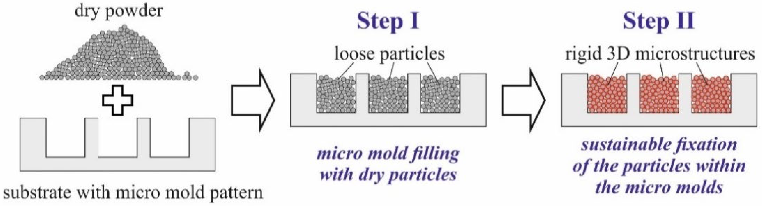
3. Mold Filling Procedures
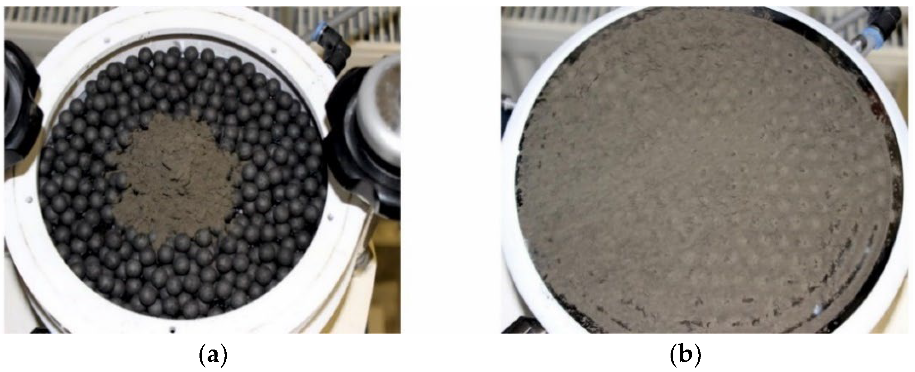
3.1. Manual Mold Filling
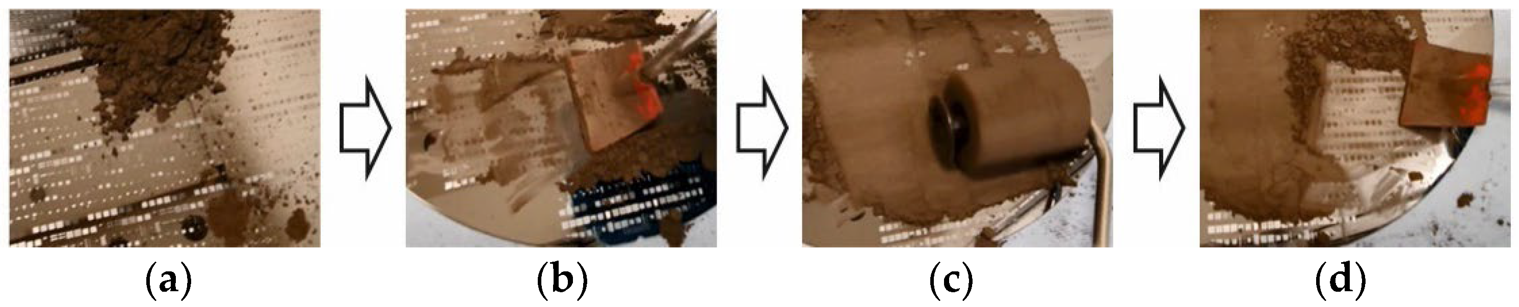
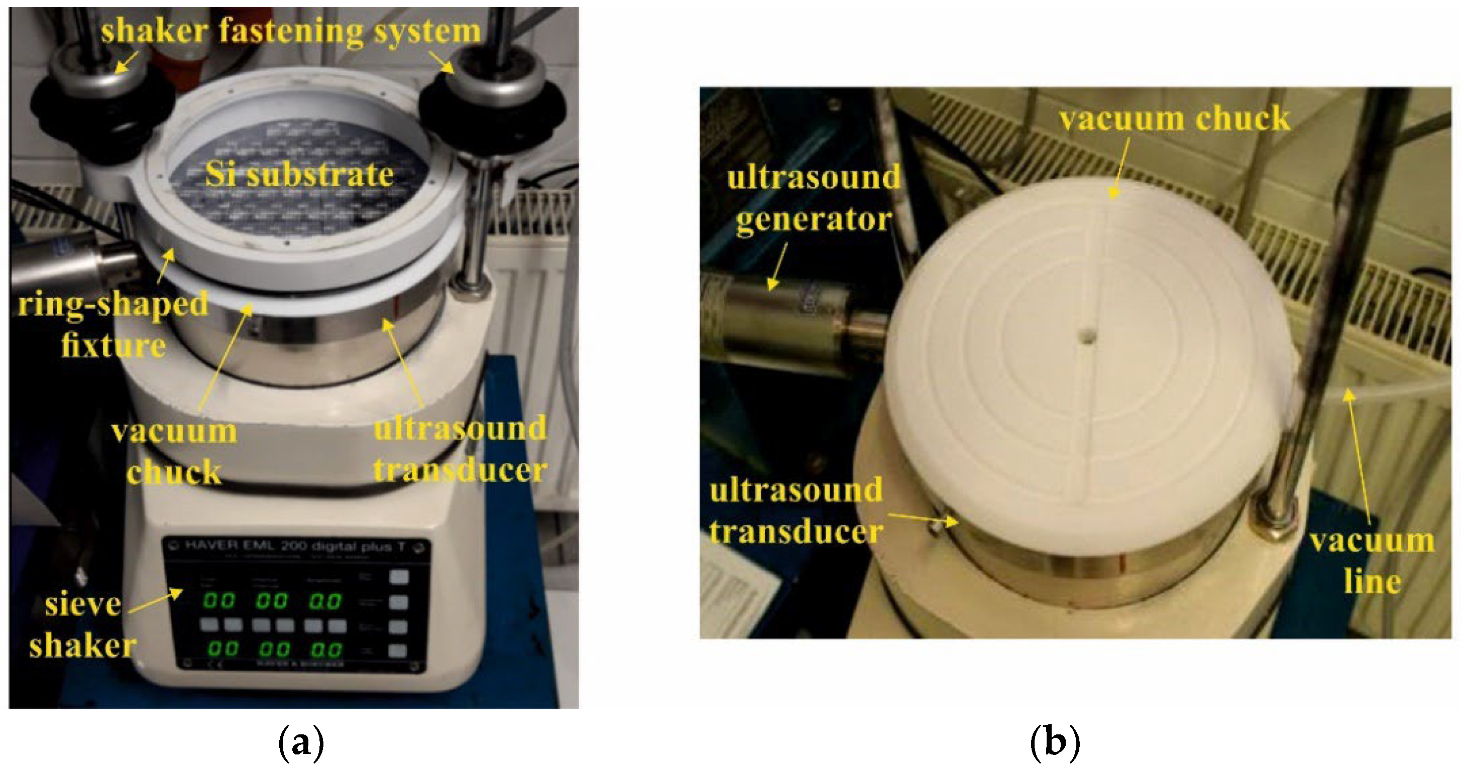
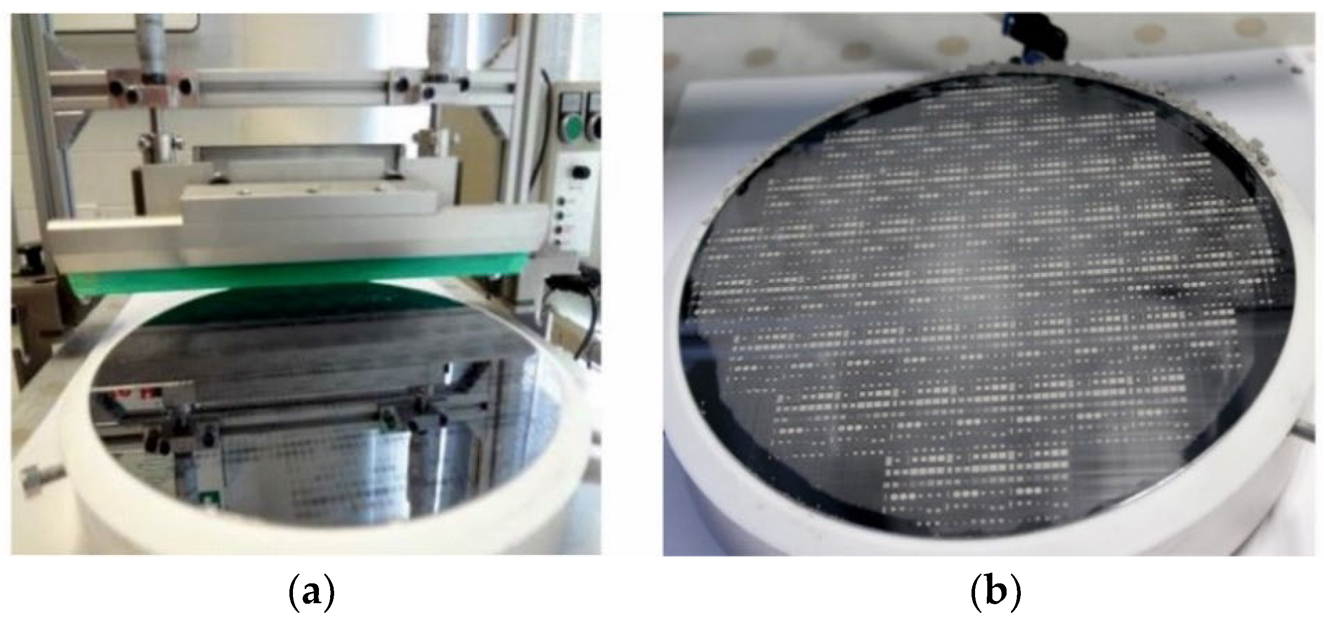
3.2. Automated Mold Filling
4. Comparison of Automated and Manual Mold Filling
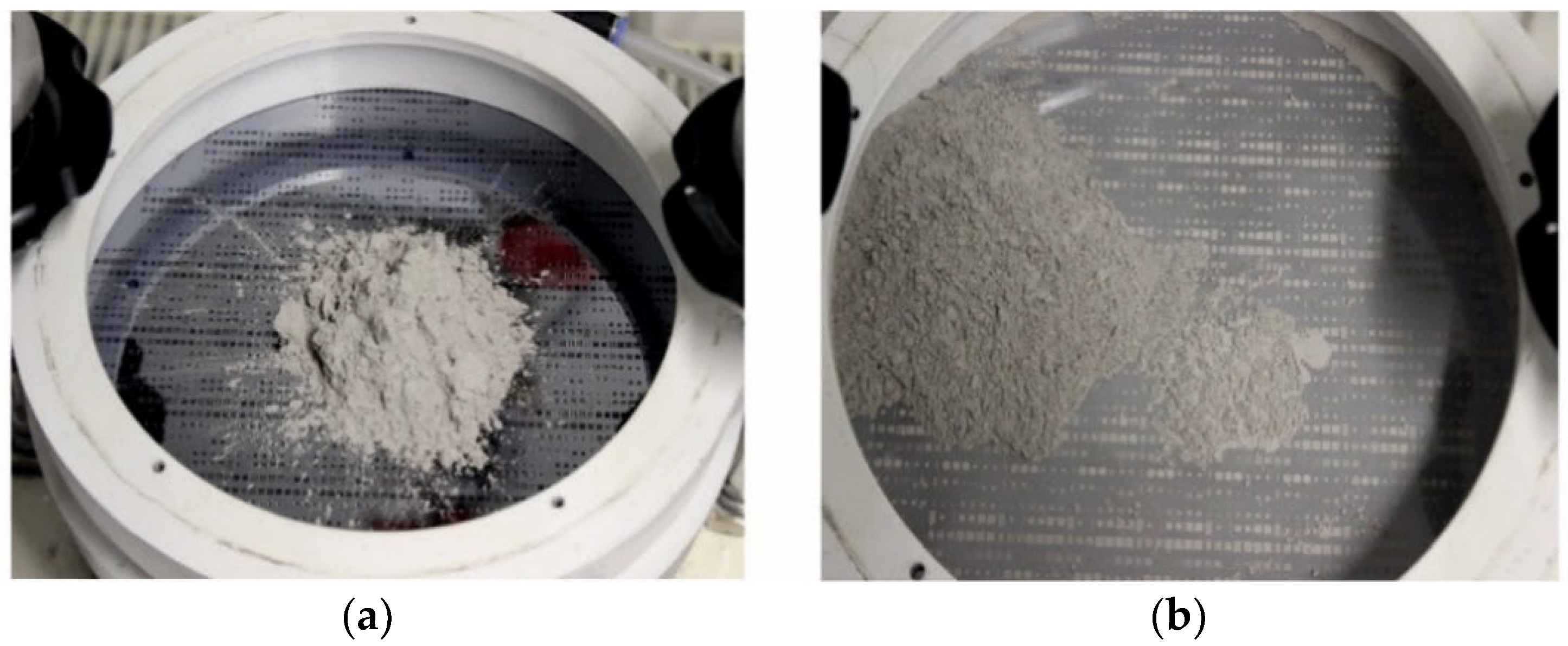
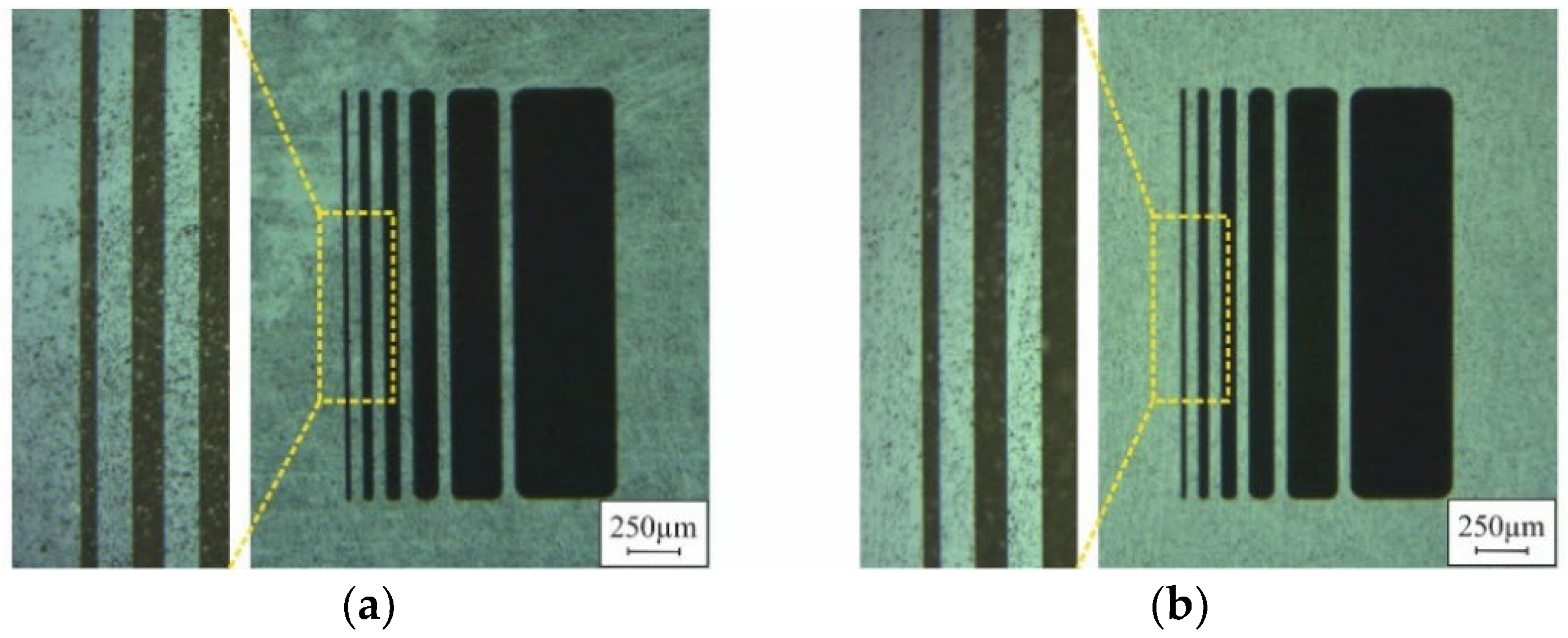
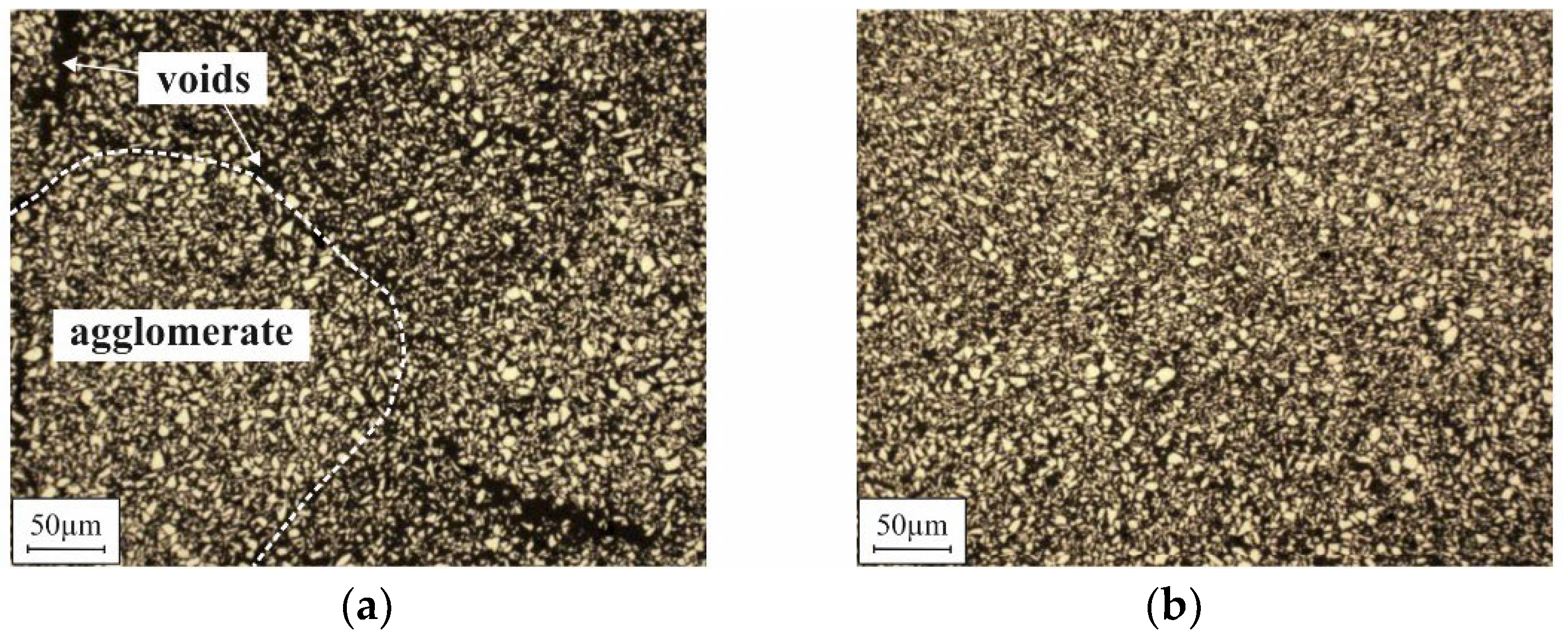
4.1. Optical Appearance of Substrate Surface
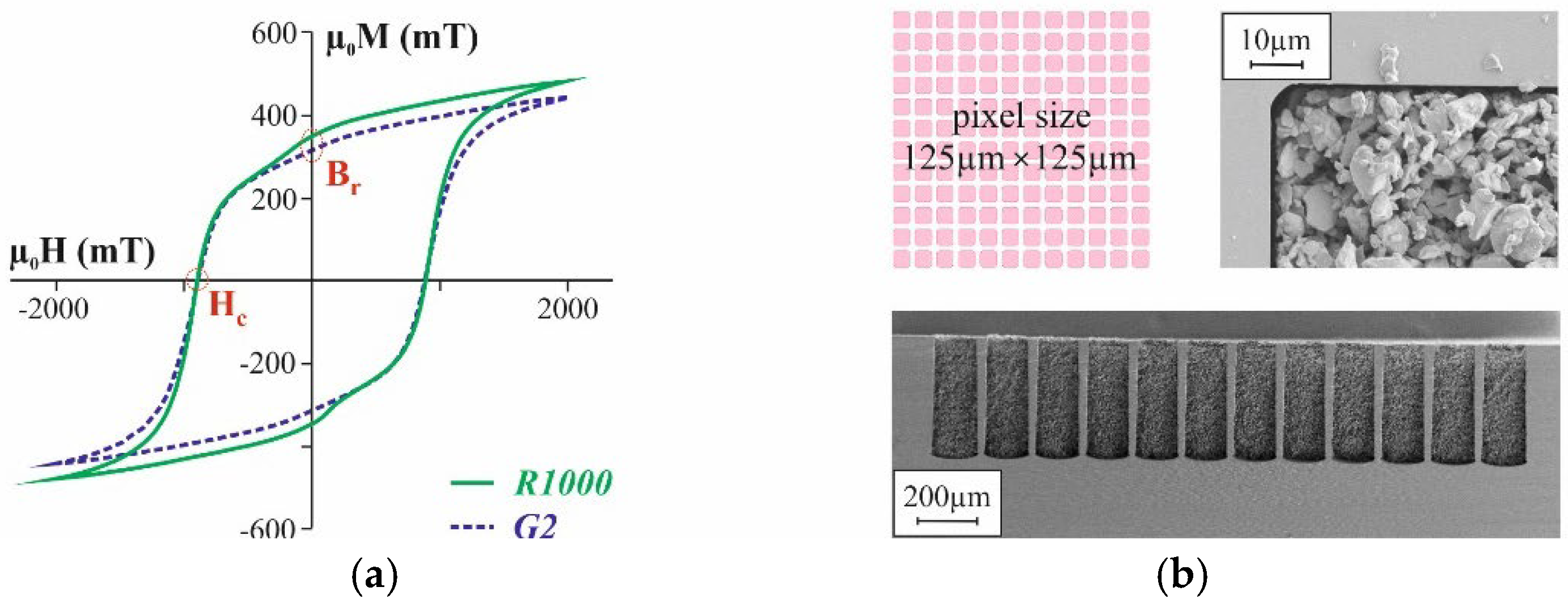
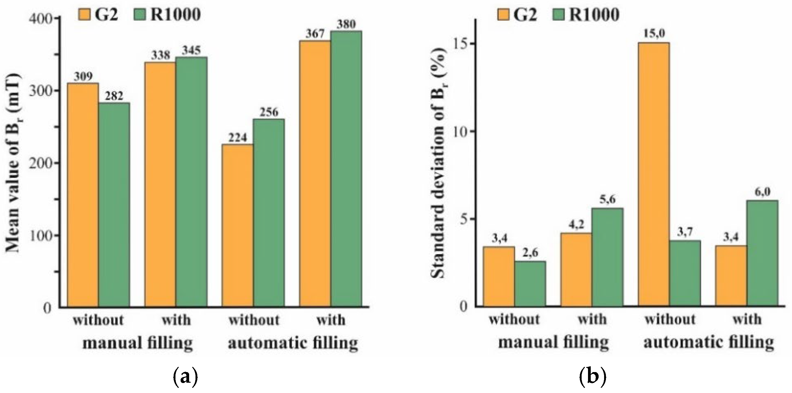
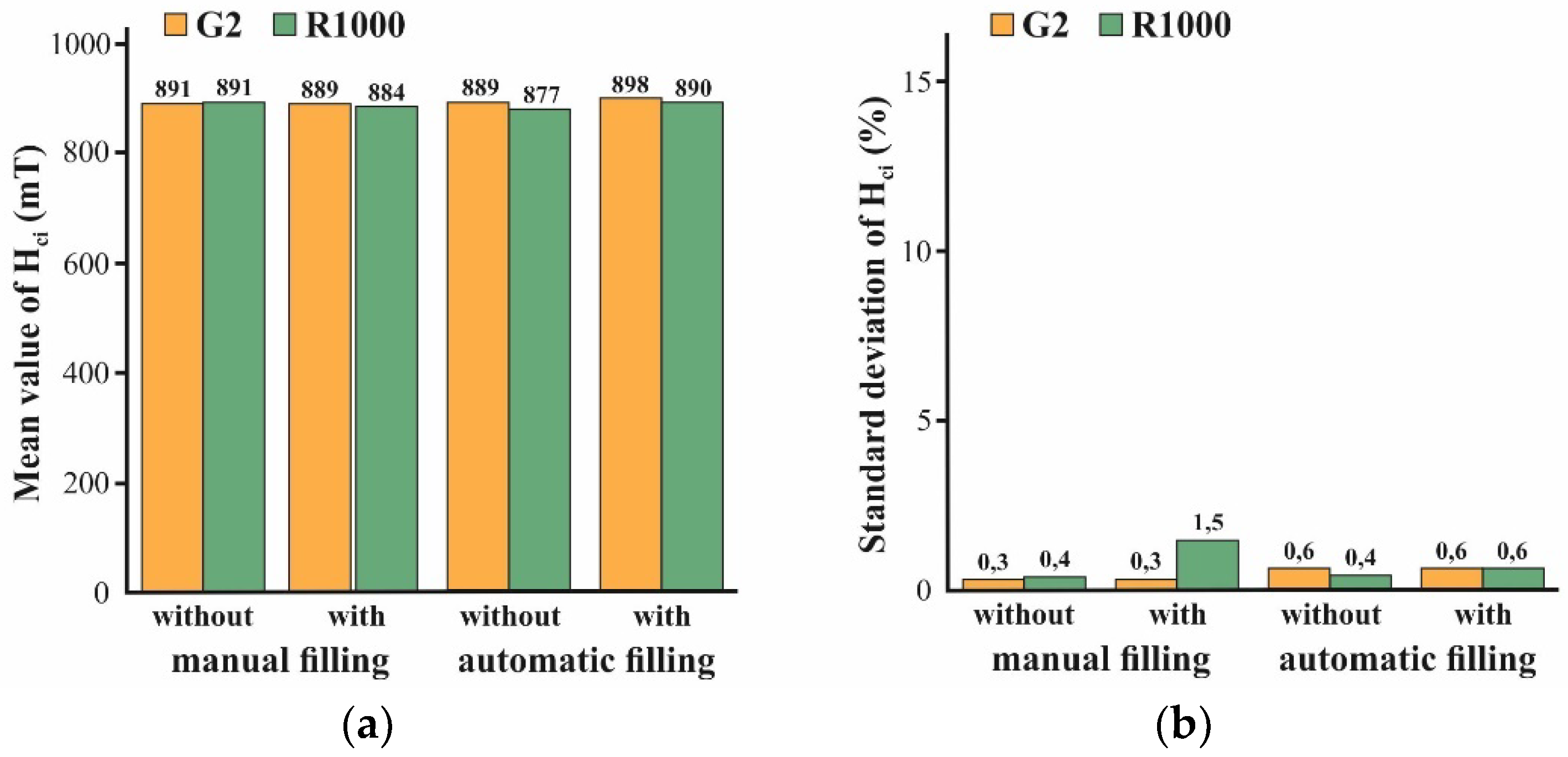
4.2. Magnetic Properties of Integrated Micromagnets
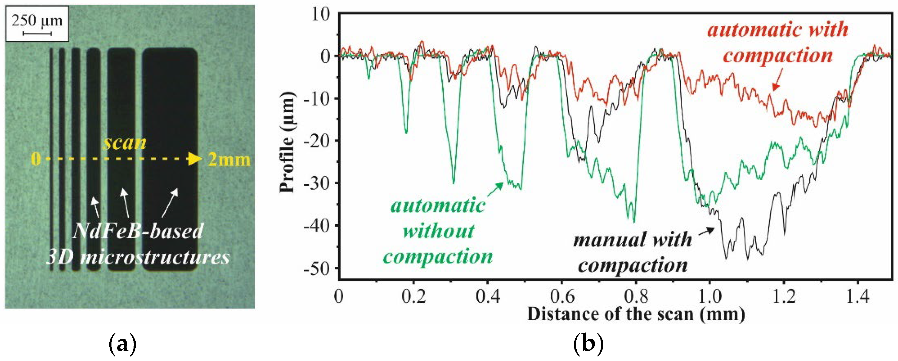
4.3. Mold Filling Height
5. Discussion
Author Contributions
Funding
Conflicts of Interest
References
- Agarwala, M.; Bourell, D.; Beaman, J.; Marcus, H.; Barlow, J. Direct selective laser sintering of metals. Rapid Prototyp. J. 1995, 1, 26–36. [Google Scholar] [CrossRef]
- Clare, A.T.; Chalker, P.R.; Beaman, J.; Davies, S.; Sutcliffe, C.J.; Tsopanos, S. Selective laser melting of high aspect ratio 3D nickel-titanium structures for MEMS applications. Int. J. Mech. Mater. Des. 2008, 4, 181–187. [Google Scholar] [CrossRef]
- Sun, K.; Wei, T.-S.; Ahn, B.Y.; Seo, J.Y.; Dillon, S.J.; Lewis, J.A. 3D printing of interdigitated Li-ion microbattery architectures. Adv. Mater. 2013, 25, 4539–4543. [Google Scholar] [CrossRef]
- Pallapa, M.; Yeow, J.T.W. A review of the hybrid techniques for the fabrication of hard magnetic microactuators based on bonded magnetic powders. Smart Mater. Struct. 2015, 24, 025007. [Google Scholar] [CrossRef]
- Bowers, B.J.; Agashe, J.S.; Arnold, D.P. A method to form bonded micromagnets embedded in silicon. In Proceedings of the TRANSDUCERS 2007, Lyon, France, 10–14 June 2007; pp. 1585–1588. [Google Scholar]
- Oniku, O.D.; Bowers, B.J.; Shetye, S.B.; Wang, N.; Arnold, D.P. Permanent magnet microstructures using dry pressed magnetic powders. J. Micromech. Microeng. 2013, 23, 075027. [Google Scholar] [CrossRef]
- Lisec, T.; Reimer, T.; Knez, M.; Chemnitz, S.; Schulz-Walsemann, A.V.; Kulkarni, A. A novel fabrication technique for MEMS based on agglomeration of powder by ALD. J. Microelectromech. Systems 2017, 26, 1093–1098. [Google Scholar] [CrossRef]
- Bodduluri, M.T.; Lisec, T.; Blohm, L.; Lofink, F.; Wagner, B. High-performance integrated hard magnets for MEMS applications. In Proceedings of the MikroSystemTechnik Kongress 2019, Berlin, Germany, 28–30 October 2019; pp. 150–153. [Google Scholar]
- Lisec, T.; Bodduluri, M.T.; Schulz-Walsemann, A.V.; Blohm, L.; Pieper, I.; Gu-Stoppel, S.; Niekiel, F.; Lofink, F.; Wagner, B. Integrated high power micro magnets for MEMS sensors and actuators. In Proceedings of the TRANSDUCERS 2019, Berlin, Germany, 23–27 June 2019; pp. 1768–1771. [Google Scholar]


| Powder | Size Distribution (µm) | Apparent Density (g/cm3) | Tap Density (g/cm3) | Surface Adhesion Characterization | |||
|---|---|---|---|---|---|---|---|
| d10 | d50 | d90 | std. dev. | ||||
| 2.2 µm Al2O3 (Almatis) | 0.7692 | 2.3773 | 5.6045 | 2.0045 | 0.9327 | 1.3324 | intermittent film |
| 10 µm Al2O3 (Almatis) | 1.6469 | 7.1142 | 15.0066 | 10.8078 | 1.1967 | 1.6894 | intermittent film |
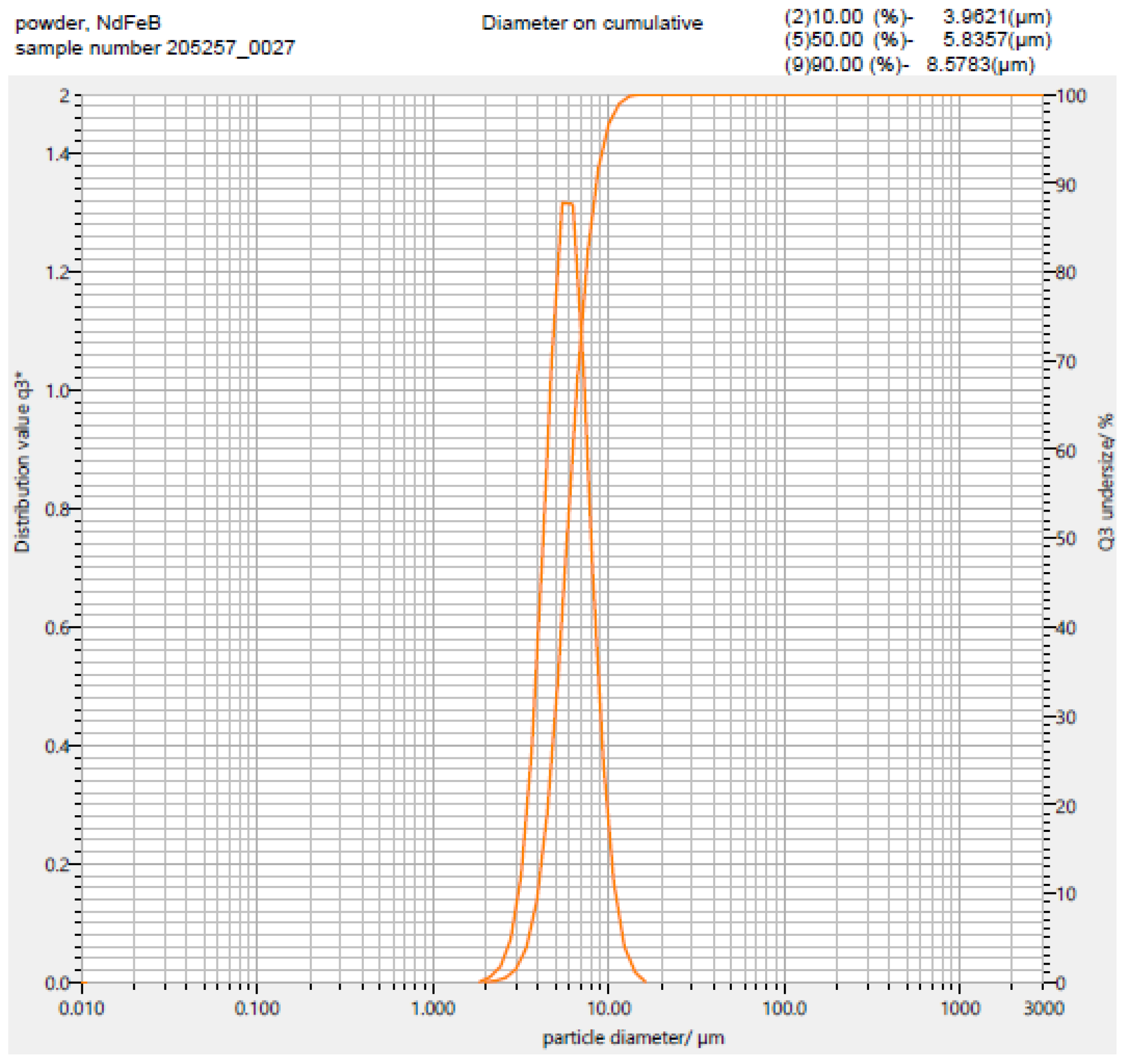
| 5 µm NdFeB Magnequench) | 3.9621 | 5.8357 | 8.5783 | 1.8556 | 1.8817 | 2.6881 | closed film with selective clustering |
| Rubber Balls (Ø 10 mm) | Amount of Powder | Sieve Shaker | Ultrasound Transducer | Duration | ||
|---|---|---|---|---|---|---|
| Frequency | Amplitude | Frequency | Amplitude | |||
| no | 50 g | 50 Hz | 0.5–2 mm | 20–60 kHz | 1–4 µm | 640 s |
| yes | 180 s | |||||
| Blade Speed | Gap 1st Cycle | Gap 2nd Cycle | Gap 3rd Cycle |
|---|---|---|---|
| 80 mm/s | 200 µm | 50 µm | 5 µm |
Publisher’s Note: MDPI stays neutral with regard to jurisdictional claims in published maps and institutional affiliations. |
© 2021 by the authors. Licensee MDPI, Basel, Switzerland. This article is an open access article distributed under the terms and conditions of the Creative Commons Attribution (CC BY) license (https://creativecommons.org/licenses/by/4.0/).
Share and Cite
Kostmann, C.; Lisec, T.; Bodduluri, M.T.; Andersen, O. Automated Filling of Dry Micron-Sized Particles into Micro Mold Pattern within Planar Substrates for the Fabrication of Powder-Based 3D Microstructures. Micromachines 2021, 12, 1176. https://doi.org/10.3390/mi12101176
Kostmann C, Lisec T, Bodduluri MT, Andersen O. Automated Filling of Dry Micron-Sized Particles into Micro Mold Pattern within Planar Substrates for the Fabrication of Powder-Based 3D Microstructures. Micromachines. 2021; 12(10):1176. https://doi.org/10.3390/mi12101176
Chicago/Turabian StyleKostmann, Cris, Thomas Lisec, Mani Teja Bodduluri, and Olaf Andersen. 2021. "Automated Filling of Dry Micron-Sized Particles into Micro Mold Pattern within Planar Substrates for the Fabrication of Powder-Based 3D Microstructures" Micromachines 12, no. 10: 1176. https://doi.org/10.3390/mi12101176
APA StyleKostmann, C., Lisec, T., Bodduluri, M. T., & Andersen, O. (2021). Automated Filling of Dry Micron-Sized Particles into Micro Mold Pattern within Planar Substrates for the Fabrication of Powder-Based 3D Microstructures. Micromachines, 12(10), 1176. https://doi.org/10.3390/mi12101176