MEMS Mirrors for LiDAR: A Review


Abstract
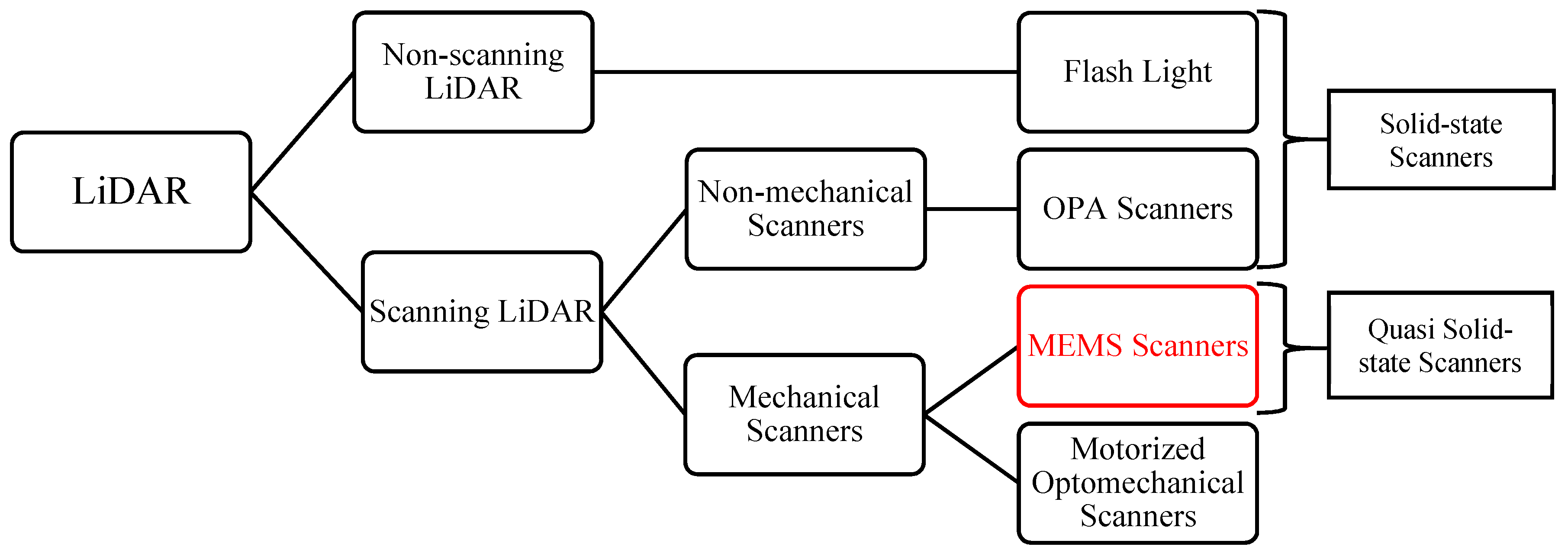
1. Introduction
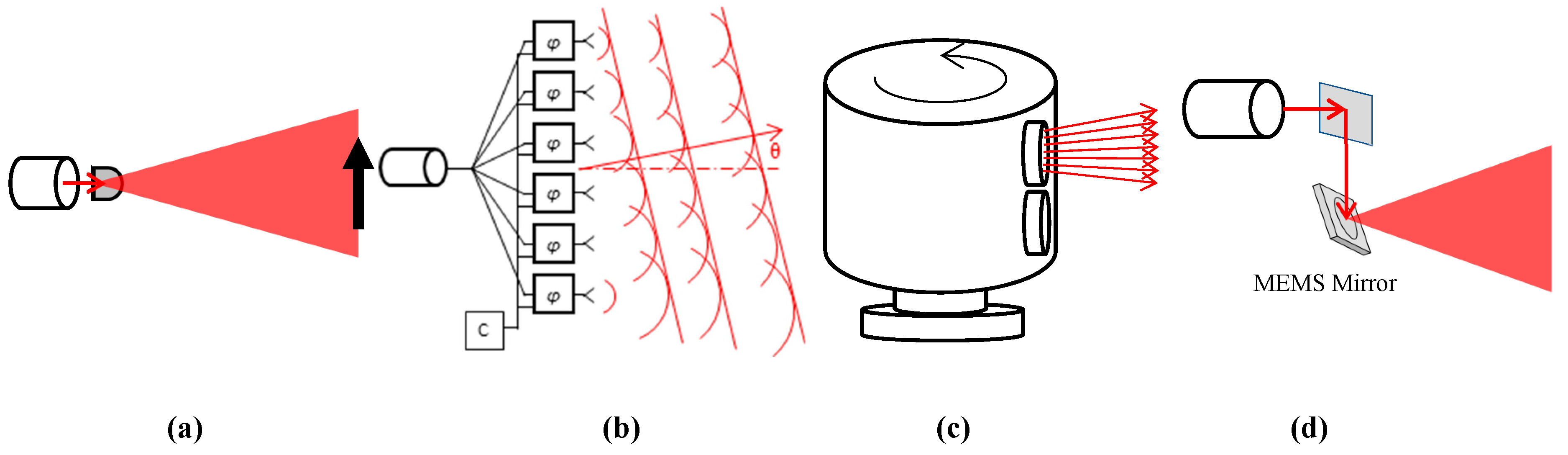
1.1. Non-Scanning LiDAR
1.2. Non-Mechanical Scanning LiDAR
1.3. Motorized Optomechanical Scanning LiDAR
1.4. MEMS Mirror-Based Quasi Solid-State LiDAR
1.5. The Scope and Organization of this Review Article
2. Laser Scanning Metrics for MEMS LiDAR
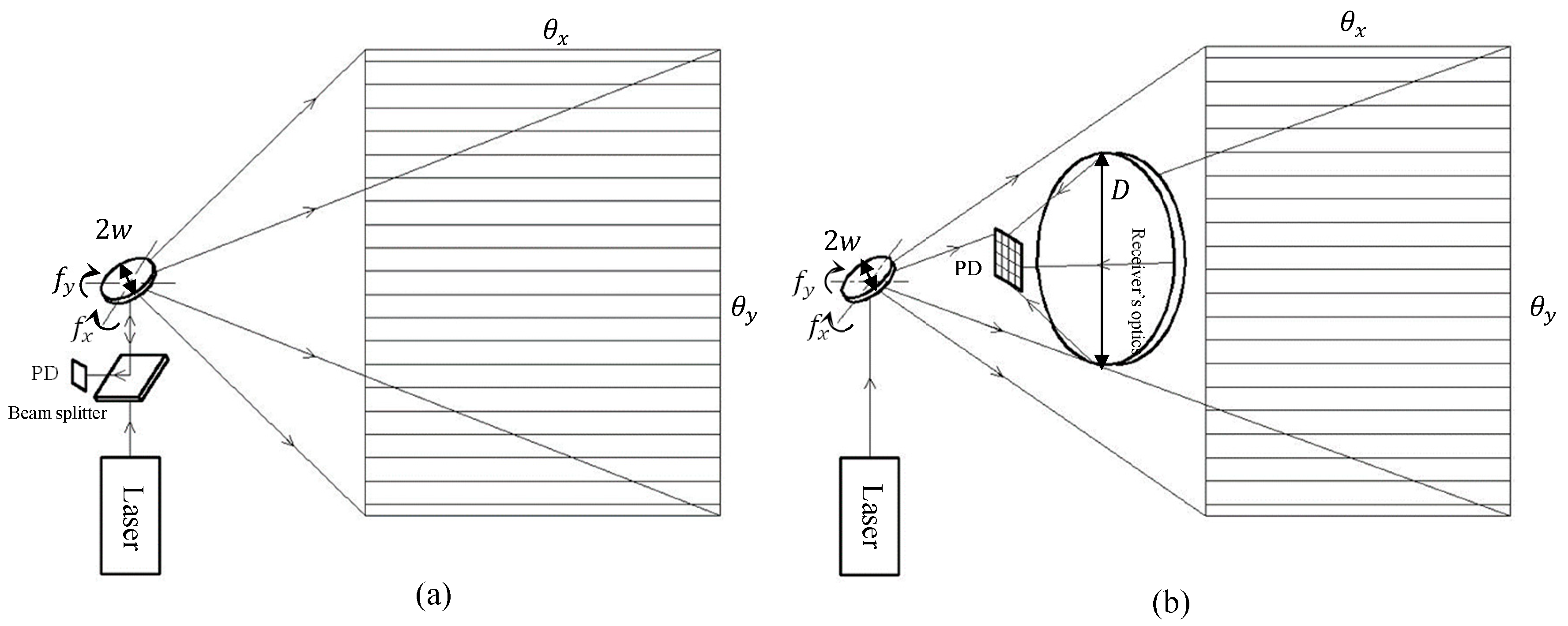
2.1. Scanning FoV
2.2. Scanner’s Optical Aperture
- Pr = received signal power (W);
- Ps = source laser power (W);
- ηt = transmitter optical efficiency;
- ρ = the reflectivity of the target object;
- r = range from the transmitter to the target (m);
- D = receiver aperture diameter (m);
- ηr = receiver optical efficiency.
2.3. Scanning Speed and Resonant Frequency
2.4. Scanner’s Size and Weight
2.5. Typical Requirements for MEMS Mirrors for LiDAR Applications
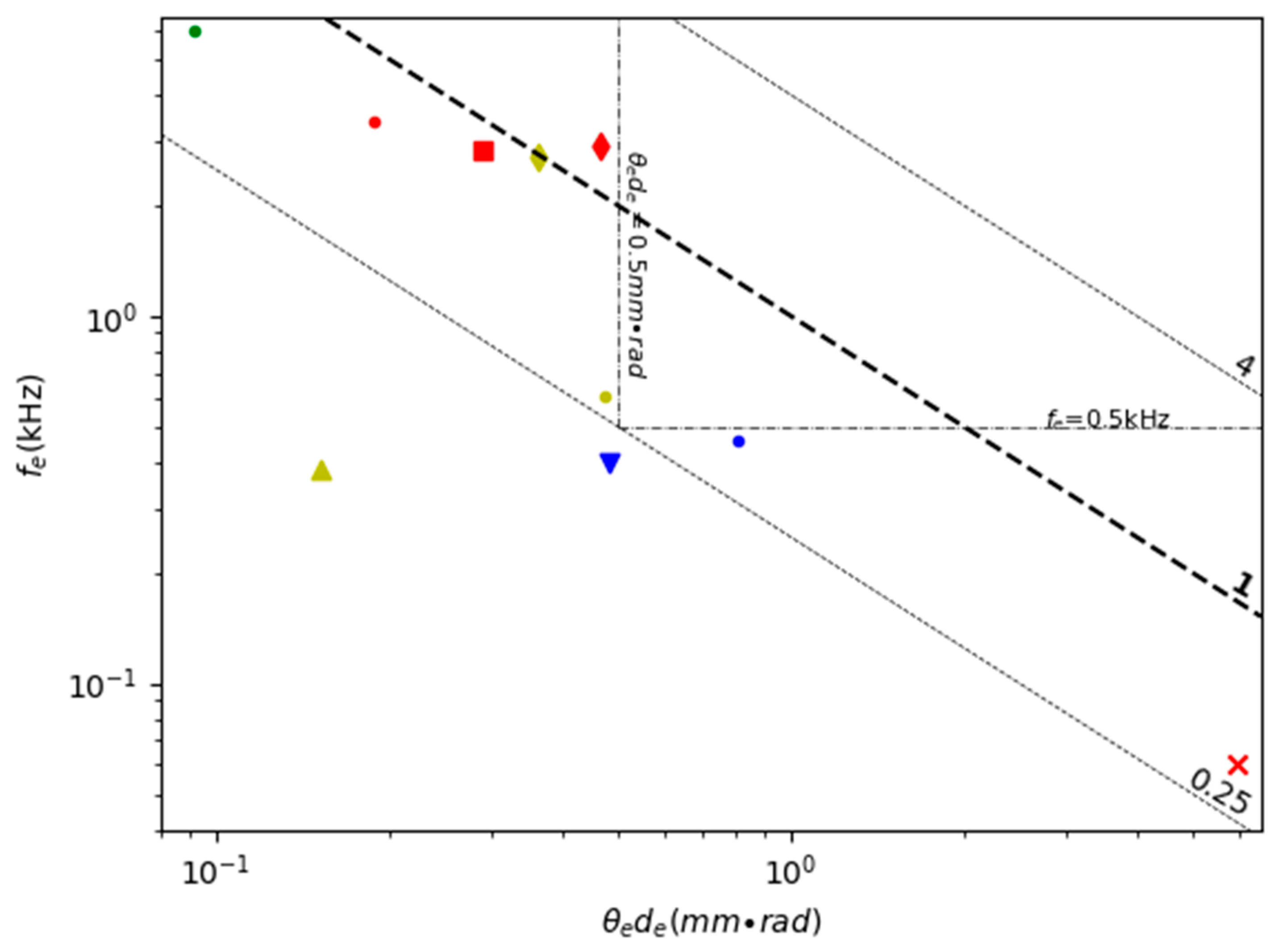
2.6. Figure of Merit
3. 1D MEMS Mirrors
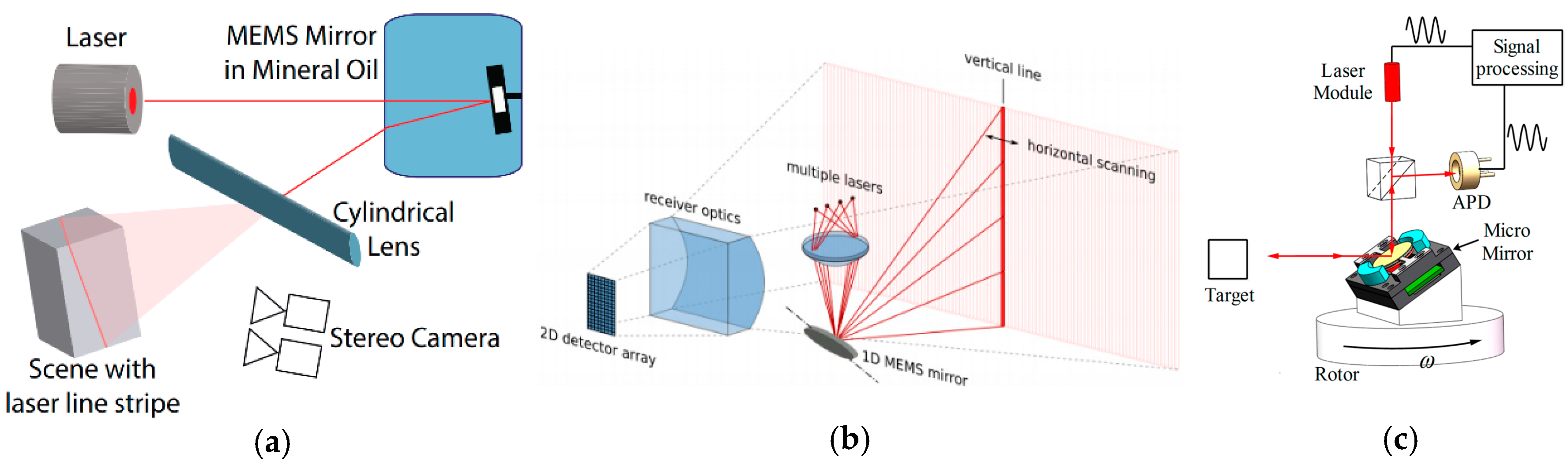
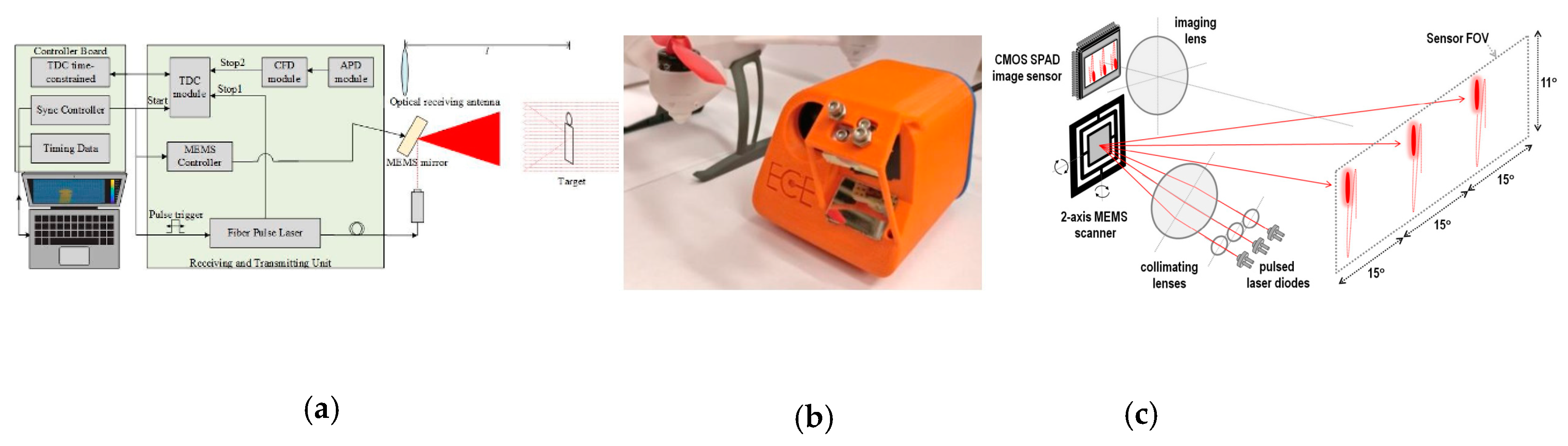
3.1. The Architectures of LiDAR with 1D MEMS Mirrors
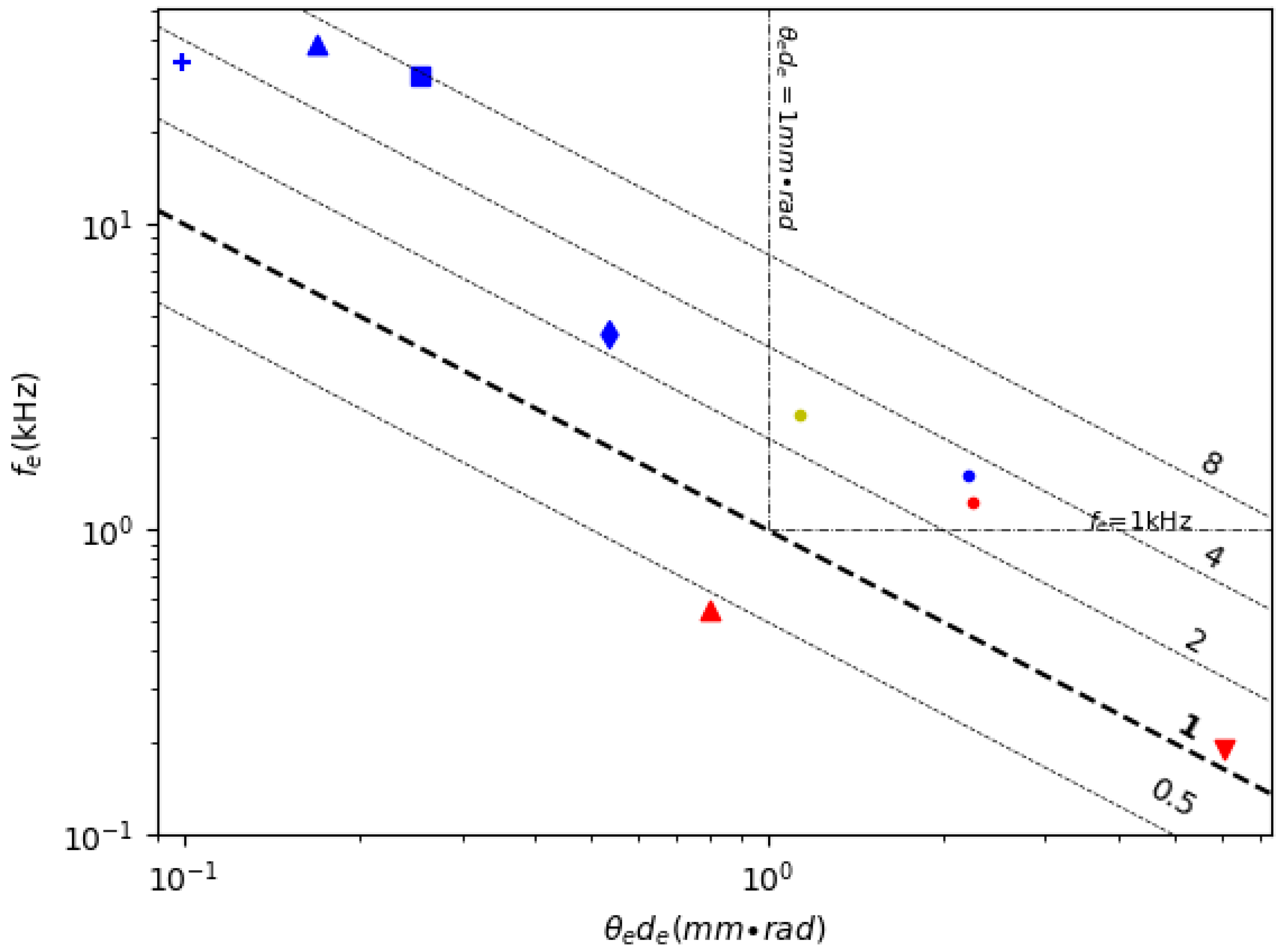
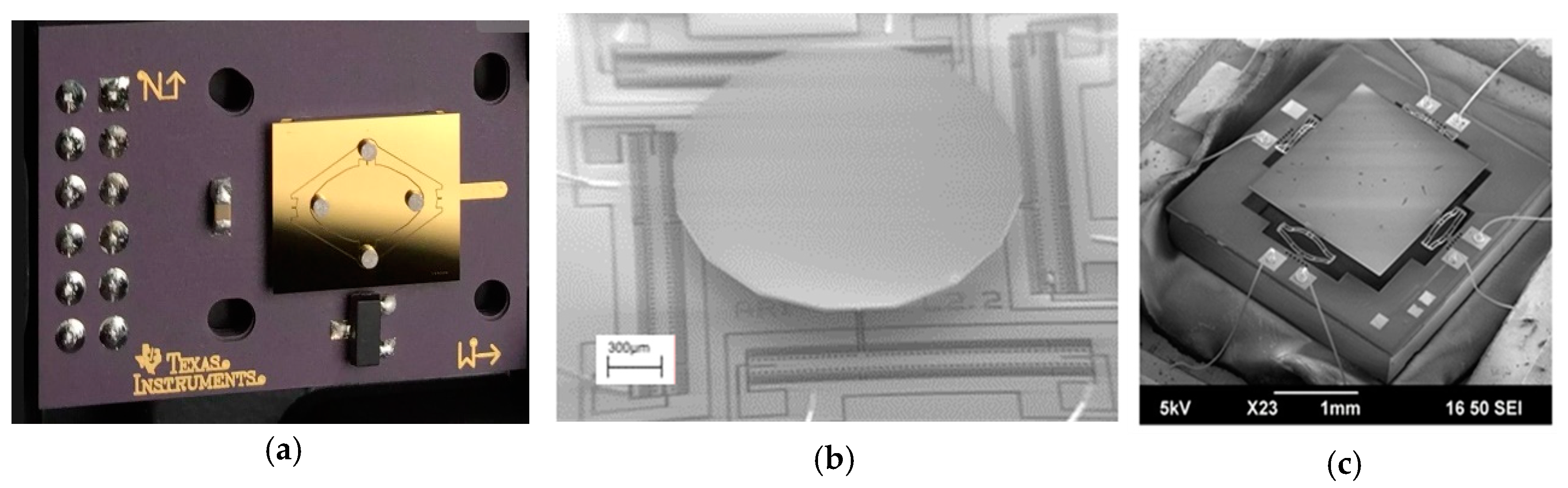
3.2. Resonant Scanning 1D MEMS Mirrors
3.3. Non-Resonant Scanning 1D MEMS Mirror
4. 2D MEMS Mirrors for LiDAR
4.1. Architecture of LiDAR with 2D MEMS Mirrors
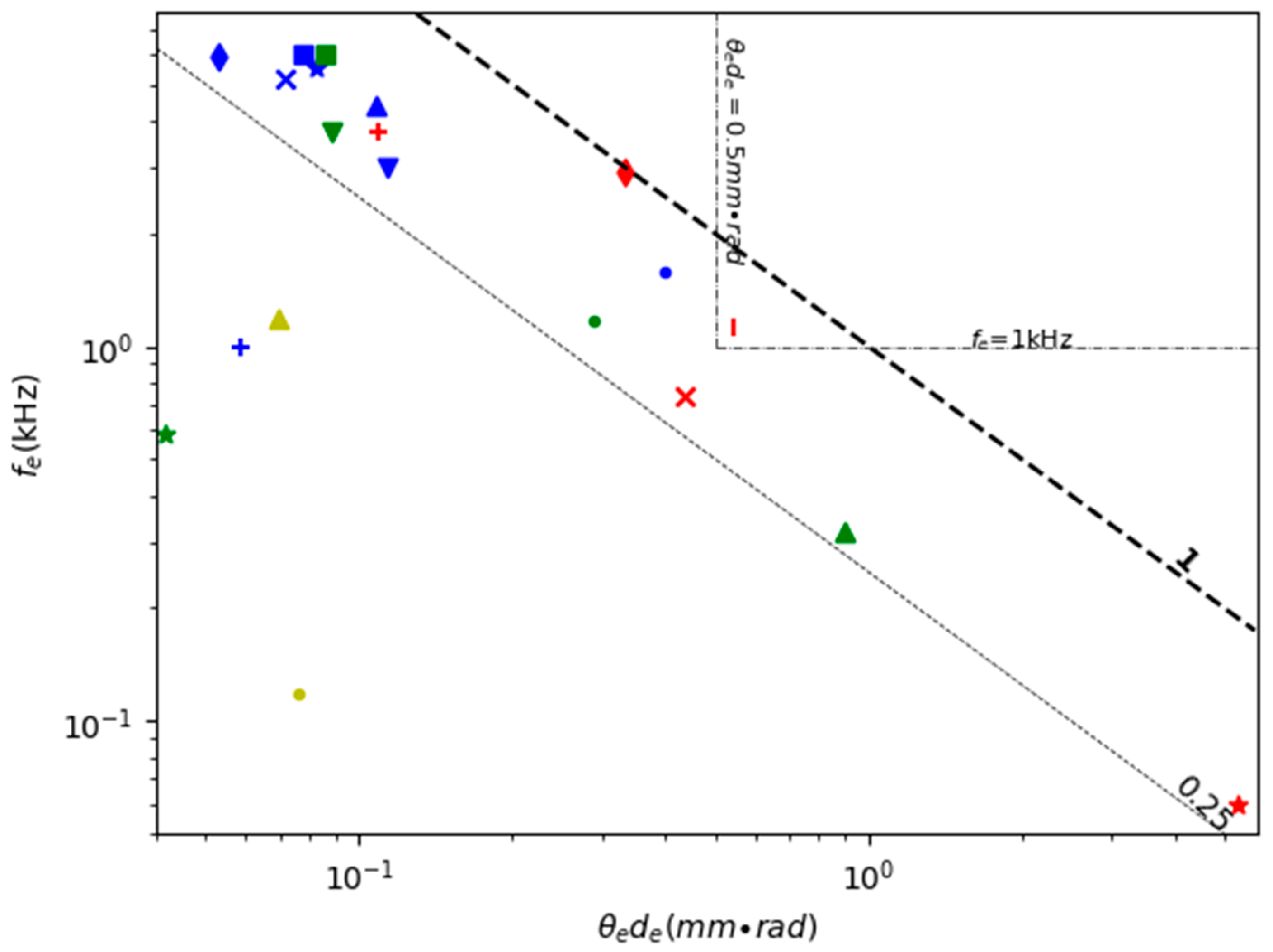
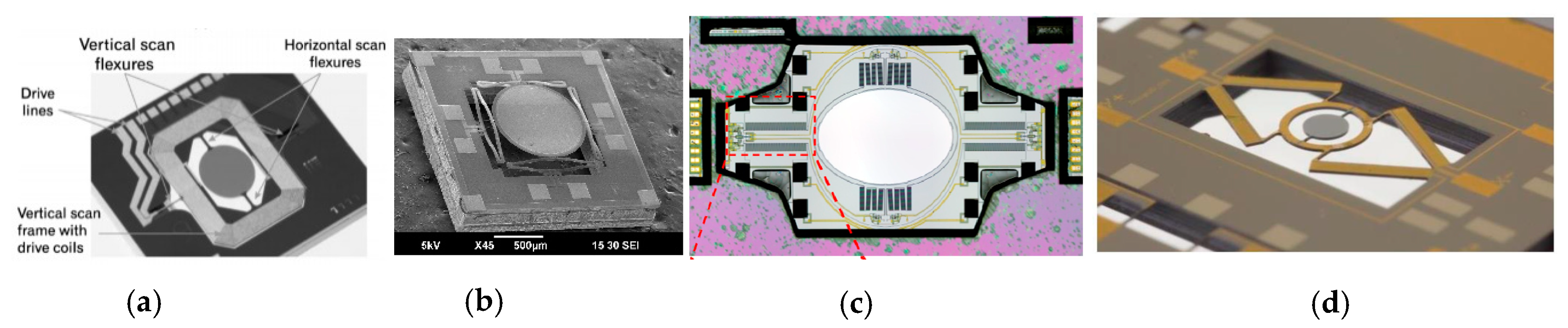
4.2. Double Resonant Scanning
4.3. Double Non-Resonant Scanning
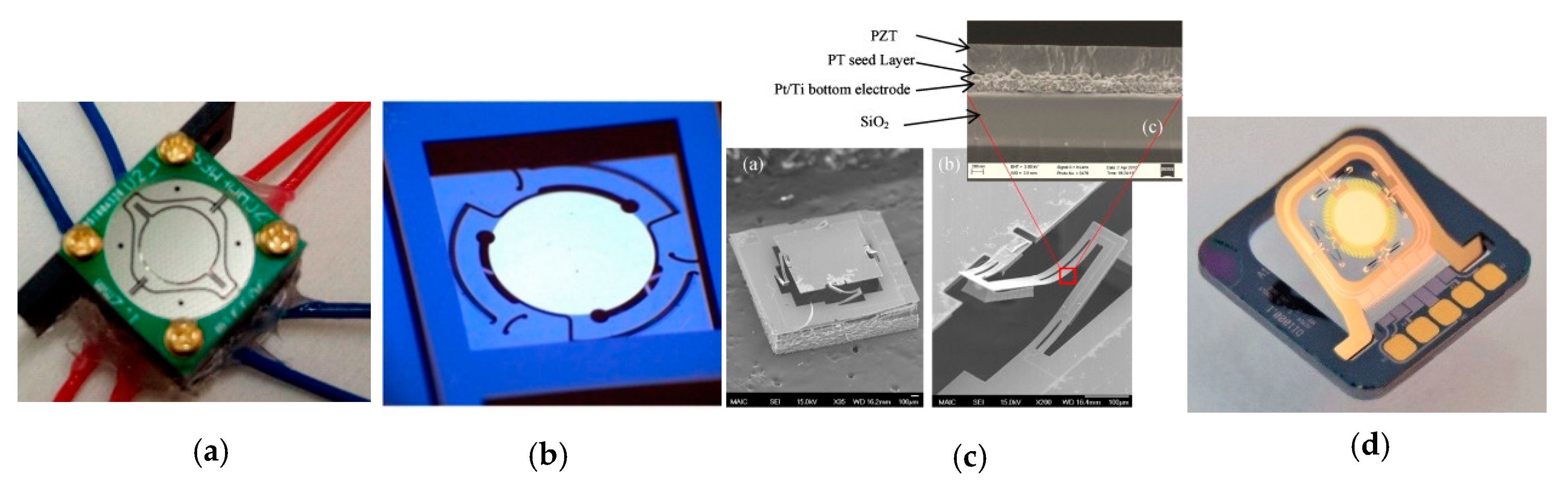
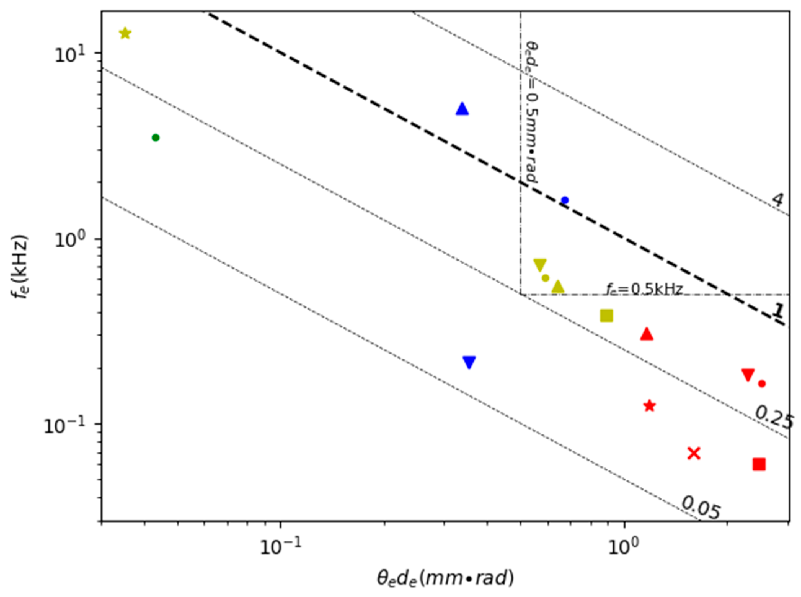
4.4. Non-Resonant Plus Resonant Scanning
5. Summary and Outlook
Author Contributions
Funding
Conflicts of Interest
References
- Goyer, G.G.; Watson, R. The Laser and its Application to Meteorology. Bull. Am. Meteorol. Soc. 1963, 44, 564–570. [Google Scholar] [CrossRef]
- Lin, S.; Cong, L.; Liangfu, C. LiDAR. In International Encyclopedia of Geography: People, the Earth, Environment and Technology; Wiley-Blackwell: Oxford, UK, 2016; pp. 1–9. [Google Scholar]
- Weiss, U.; Biber, P.; Laible, S.; Bohlmann, K.; Zell, A. Plant Species Classification Using a 3D LIDAR Sensor and Machine Learning. In Proceedings of the 2010 Ninth International Conference on Machine Learning and Applications, Washington, DC, USA, 12–14 December 2010; pp. 339–345. [Google Scholar]
- Badarinath, K.; Kharol, S.K.; Sharma, A.R. Long-range transport of aerosols from agriculture crop residue burning in Indo-Gangetic Plains—A study using LIDAR, ground measurements and satellite data. J. Atmos. Solar Terr. Phys. 2009, 71, 112–120. [Google Scholar] [CrossRef]
- Hening, S.; Ippolito, C.A.; Krishnakumar, K.; Stepanyan, V.; Teodorescu, M. 3D LiDAR SLAM Integration with GPS/INS for UAVs in Urban GPS-Degraded Environments. AIAA Inf. Syst. AIAA Infotech Aerosp. 2017, 448. [Google Scholar] [CrossRef]
- Maturana, D.; Scherer, S. VoxNet: A 3D Convolutional Neural Network for real-time object recognition. In Proceedings of the 2015 IEEE/RSJ International Conference on Intelligent Robots and Systems (IROS), Hamburg, Germany, 28 September–2 October 2015; pp. 922–928. [Google Scholar]
- Miyasaka, T.; Ohama, Y.; Ninomiya, Y. Ego-motion estimation and moving object tracking using multi-layer LIDAR. In Proceedings of the 2009 IEEE intelligent vehicles symposium, Xi’an, China, 3–5 June 2009; pp. 151–156. [Google Scholar]
- Gelbart, A.; Redman, B.C.; Light, R.S.; Schwartzlow, C.A.; Griffis, A.J. Flash lidar based on multiple-slit streak tube imaging lidar. In Laser Radar Technology and Applications VII; SPIE Press: Bellingham, WA, USA, 2002; pp. 9–18. [Google Scholar]
- McManamon, P.F.; Bos, P.J.; Escuti, M.; Heikenfeld, J.; Serati, S.; Xie, H.; Watson, E.A. A Review of Phased Array Steering for Narrow-Band Electrooptical Systems. Proc. IEEE 2009, 97, 1078–1096. [Google Scholar] [CrossRef]
- Pacala, A. How Multi-Beam Flash Lidar Works. Available online: https://ouster.com/blog/how-multi-beam-flash-lidar-works (accessed on 24 March 2020).
- Liu, J.; Sun, Q.; Fan, Z.; Jia, Y. TOF Lidar Development in Autonomous Vehicle. In 2018 IEEE 3rd Optoelectronics Global Conference (OGC); Institute of Electrical and Electronics Engineers (IEEE): Piscataway, NJ, USA, 2018; pp. 185–190. [Google Scholar]
- Kim, G.; Park, Y. LIDAR pulse coding for high resolution range imaging at improved refresh rate. Opt. Express 2016, 24, 23810. [Google Scholar] [CrossRef] [PubMed]
- Wight, D.R.; Heaton, J.M.; Hughes, B.T.; Birbeck, J.C.H.; Hilton, K.P.; Taylor, D.J. Novel phased array optical scanning device implemented using GaAs/AlGaAs technology. Appl. Phys. Lett. 1991, 59, 899–901. [Google Scholar] [CrossRef]
- McManamon, P.; Dorschner, T.; Corkum, D.; Friedman, L.; Hobbs, D.; Holz, M.; Liberman, S.; Resler, D.; Sharp, R.; Watson, E.; et al. Optical phased array technology. Proc. IEEE 1996, 84, 268–298. [Google Scholar] [CrossRef]
- Wang, Y.; Wu, M.C. Micromirror based optical phased array for wide-angle beamsteering. In Proceedings of the 2017 IEEE 30th International Conference on Micro Electro Mechanical Systems (MEMS), Las Vegas, NV, USA, 22–26 January 2017; pp. 897–900. [Google Scholar]
- Resler, D.P.; Hobbs, D.S.; Sharp, R.C.; Friedman, L.J.; Dorschner, T.A. High-efficiency liquid-crystal optical phased-array beam steering. Opt. Lett. 1996, 21, 689. [Google Scholar] [CrossRef]
- Hah, D.; Huang, S.-Y.; Tsai, J.-C.; Toshiyoshi, H.; Wu, M. Low-Voltage, Large-Scan Angle MEMS Analog Micromirror Arrays with Hidden Vertical Comb-Drive Actuators. J. Microelectromech. Syst. 2004, 13, 279–289. [Google Scholar] [CrossRef]
- Ryf, R.; Stuart, H.R.; Giles, C.R. MEMS tip/tilt and piston mirror arrays as diffractive optical elements. In Advanced Wavefront Control: Methods, Devices, and Applications III; International Society for Optics and Photonics: Bellingham, WA, USA, 2005; p. 58940C. [Google Scholar]
- Sun, J.; Timurdogan, E.; Yaacobi, A.; Hosseini, E.S.; Watts, M.R. Large-scale nanophotonic phased array. Nature 2013, 493, 195–199. [Google Scholar] [CrossRef]
- Van Acoleyen, K.; Bogaerts, W.; Jagerska, J.; Le Thomas, N.; Houdré, R.; Baets, R. Off-chip beam steering with a one-dimensional optical phased array on silicon-on-insulator. Opt. Lett. 2009, 34, 1477–1479. [Google Scholar] [CrossRef] [PubMed]
- Sun, J.; Hosseini, E.S.; Yaacobi, A.; Cole, D.; Leake, G.; Coolbaugh, D.; Watts, M.R. Two-dimensional apodized silicon photonic phased arrays. Opt. Lett. 2014, 39, 367–370. [Google Scholar] [CrossRef] [PubMed]
- Chung, S.; Abediasl, H.; Hashemi, H. 15.4 A 1024-element scalable optical phased array in 0.18 µm SOI CMOS. In Proceedings of the 2017 IEEE International Solid-State Circuits Conference (ISSCC), San Francisco, CA, USA, 5–9 February 2017; pp. 262–263. [Google Scholar]
- Martin, A.; Verheyen, P.; De Heyn, P.; Absil, P.; Feneyrou, P.; Bourderionnet, J.; Dodane, D.; Leviandier, L.; Dolfi, D.; Naughton, A.; et al. Photonic Integrated Circuit-Based FMCW Coherent LiDAR. J. Light. Technol. 2018, 36, 4640–4645. [Google Scholar] [CrossRef]
- Jingye, C.; Yaocheng, S. Research progress in solid-state LiDAR. Opto-Electron. Eng. 2019, 46, 190218. [Google Scholar]
- Halterman, R.; Bruch, M. Velodyne HDL-64E lidar for unmanned surface vehicle obstacle detection. SPIE Def. Secur. Sens. 2010, 7692, 76920. [Google Scholar] [CrossRef]
- Dong, L.; Zhu, W.; Zhao, Y.; Liu, X.; Zhang, J.; Liu, W.; Zhou, X. A novel optical-mechanical scanning passive THz imaging system. In Proceedings of the 2012 37th International Conference on Infrared, Millimeter, and Terahertz Waves, Wollongong, Australia, 23–29 September 2012; pp. 1–2. [Google Scholar]
- Bogatscher, S.; Streck, A.; Fox, M.; Meinzer, S.; Heussner, N.; Stork, W. Large aperture at low cost three-dimensional time-of-flight range sensor using scanning micromirrors and synchronous detector switching. Appl. Opt. 2014, 53, 1570–1582. [Google Scholar] [CrossRef]
- Xie, H.; Aix, F.Z. Optical MEMS; MDPI: Basel, Switzerland, 2019. [Google Scholar]
- Stann, B.L.; Dammann, J.F.; Giza, M.M.; Jian, P.-S.; Lawler, W.B.; Nguyen, H.M.; Sadler, L.C. MEMS-scanned ladar sensor for small ground robots. SPIE Def. Secur. Sens. 2010, 7684, 76841. [Google Scholar] [CrossRef]
- Holmstrom, S.T.S.; Baran, U.; Urey, H. MEMS Laser Scanners: A Review. J. Microelectromech. Syst. 2014, 23, 259–275. [Google Scholar] [CrossRef]
- Sun, J.; Xie, H. MEMS-Based Endoscopic Optical Coherence Tomography. Int. J. Opt. 2011, 2011, 1–12. [Google Scholar] [CrossRef]
- Piyawattanametha, W. A review of MEMS scanner based endoscopic optical imaging probe. In Proceedings of the 2013 International Conference on Optical MEMS and Nanophotonics (OMN), Kanazawa, Japan, 18–22 August 2013; pp. 53–54. [Google Scholar]
- Baran, U.; Brown, D.; Holmstrom, S.; Balma, D.; Davis, W.O.; Muralt, P.; Urey, H. Resonant PZT MEMS Scanner for High-Resolution Displays. J. Microelectromech. Syst. 2012, 21, 1303–1310. [Google Scholar] [CrossRef]
- Tasneem, Z.; Wang, D.; Xie, H.; Sanjeev, K. Directionally Controlled Time-of-Flight Ranging for Mobile Sensing Platforms. Robot. Sci. Syst. XIV 2018, 1–10. [Google Scholar] [CrossRef]
- Tsalakanidou, F.; Förster, F.; Malassiotis, S.; Strintzis, M.G. Real-time acquisition of depth and color images using structured light and its application to 3D face recognition. Real-Time Imaging 2005, 11, 358–369. [Google Scholar] [CrossRef]
- Fernández-Díaz, J.C.; Carter, W.E.; Shrestha, R.L.; Glennie, C. Now You See It… Now You Don’t: Understanding Airborne Mapping LiDAR Collection and Data Product Generation for Archaeological Research in Mesoamerica. Remote. Sens. 2014, 6, 9951–10001. [Google Scholar] [CrossRef]
- Häne, C.; Lee, G.H.; Fraundorfer, F.; Furgale, P.; Sattler, T.; Pollefeys, M.; Heng, L. 3D visual perception for self-driving cars using a multi-camera system: Calibration, mapping, localization, and obstacle detection. Image Vis. Comput. 2017, 68, 14–27. [Google Scholar] [CrossRef]
- Ackerman, E. Lidar that will make self-driving cars affordable [News]. IEEE Spectr. 2016, 53, 14. [Google Scholar] [CrossRef]
- Huang, L.; Barth, M. Tightly-coupled LIDAR and computer vision integration for vehicle detection. In Proceedings of the 2009 IEEE Intelligent Vehicles Symposium, Xi’an, China, 3–5 June 2009; pp. 604–609. [Google Scholar] [CrossRef]
- Jayaweera, N.; Rajatheva, N.; Latva-Aho, M. Autonomous Driving without a Burden: View from Outside with Elevated LiDAR. In Proceedings of the 2019 IEEE 89th Vehicular Technology Conference (VTC2019-Spring), Kuala Lumpur, Malaysia, 28 April–1 May 2019; pp. 1–7. [Google Scholar]
- Khoury, J.; Ramanathan, R.; McCloskey, D.; Smith, R.; Campbell, T. RadarMAC: Mitigating Radar Interference in Self-Driving Cars. In Proceedings of the 2016 13th Annual IEEE International Conference on Sensing, Communication, and Networking (SECON), London, UK, 27–30 June 2016; pp. 1–9. [Google Scholar]
- Glenn, N.F.; Streutker, D.R.; Chadwick, D.J.; Thackray, G.D.; Dorsch, S.J. Analysis of LiDAR-derived topographic information for characterizing and differentiating landslide morphology and activity. Geomorphology 2006, 73, 131–148. [Google Scholar] [CrossRef]
- Sjafrie, H. Introduction to Self-Driving Vehicle Technology; CRC Press: Boca Raton, FL, USA, 2019. [Google Scholar]
- Bandres, M.A.; Gutirrez-Vega, J.; Gutiérrez-Vega, J.C. Ince Gaussian beams. Opt. Lett. 2004, 29, 144. [Google Scholar] [CrossRef] [PubMed]
- Moss, R.; Yuan, P.; Bai, X.; Quesada, E.; Sudharsanan, R.; Stann, B.L.; Dammann, J.F.; Giza, M.M.; Lawler, W.B. Low-cost compact MEMS scanning ladar system for robotic applications. SPIE Def. Secur. Sens. 2012, 8379, 837903. [Google Scholar] [CrossRef]
- Bissonnette, L.R. Multiple-scattering lidar equation. Appl. Opt. 1996, 35, 6449–6465. [Google Scholar] [CrossRef]
- Xie, H.; Pan, Y.; Fedder, G.K. A CMOS-MEMS mirror with curled-hinge comb drives. J. Microelectromech. Syst. 2003, 12, 450–457. [Google Scholar] [CrossRef]
- Lang, Q.; Sun, F.; Liu, H.; Wang, B.; Gao, M.; Li, J.; Zhang, Q. An Evaluation of 2D SLAM Techniques Based on Kinect and Laser Scanner. In Proceedings of the Springer International Conference on Cognitive Systems and Signal Processing, Beijing, China, 19–23 November 2016; pp. 276–289. [Google Scholar]
- Vaughan, O. RoboBee breaks free. Nat. Electron. 2019, 2, 265. [Google Scholar] [CrossRef]
- Kasturi, A.; Milanovic, V.; Atwood, B.H.; Yang, J. UAV-borne lidar with MEMS mirror-based scanning capability. Laser Radar Technol. Appl. XXI 2016, 9832, 98320. [Google Scholar] [CrossRef]
- Hecht, J. Lidar for Self-Driving Cars. Opt. Photon News 2018, 29, 26–33. [Google Scholar] [CrossRef]
- Zhang, X.; Koppal, S.J.; Zhang, R.; Zhou, L.; Butler, E.; Xie, H. Wide-angle structured light with a scanning MEMS mirror in liquid. Opt. Express 2016, 24, 3479–3487. [Google Scholar] [CrossRef]
- Hughes, M. Solid-State LiDAR Is Coming to an Autonomous Vehicle Near You. Available online: https://www.allaboutcircuits.com/news/solid-state-LiDAR-is-coming-to-an-autonomous-vehicle-near-you/ (accessed on 22 April 2020).
- Maksymova, I.; Greiner, P.; Niedermueller, L.C.; Druml, N. Detection and Compensation of Periodic Jitters of Oscillating MEMS Mirrors used in Automotive Driving Assistance Systems. In Proceedings of the 2019 IEEE Sensors Applications Symposium (SAS), Sophia Antipolis, France, 11–13 March 2019; pp. 1–5. [Google Scholar]
- Yoo, H.W.; Druml, N.; Brunner, D.; Schwarzl, C.; Thurner, T.; Hennecke, M.; Schitter, G. MEMS-based lidar for autonomous driving. Elektrotechnik Inf. 2018, 135, 408–415. [Google Scholar] [CrossRef]
- Ye, L.; Zhang, G.; You, Z. Large-Aperture kHz Operating Frequency Ti-alloy Based Optical Micro Scanning Mirror for LiDAR Application. Micromachines 2017, 8, 120. [Google Scholar] [CrossRef]
- Tseng, V.F.-G.; Xie, H. Simultaneous piston position and tilt angle sensing for large vertical displacement micromirrors by frequency detection inductive sensing. Appl. Phys. Lett. 2015, 107, 214102. [Google Scholar] [CrossRef]
- Sasaki, M.; Tabata, M.; Haga, T.; Hane, K. Piezoresistive rotation angle sensor integrated in micromirror. Jpn. J. Appl. Phys. 2006, 45, 3789. [Google Scholar] [CrossRef]
- Aoyagi, I.; Shimaoka, K.; Kato, S.; Makishi, W.; Kawai, Y.; Tanaka, S.; Ono, T.; Esashi, M.; Hane, K. 2-axis MEMS scanner for a laser range finder. In Proceedings of the 16th IEEE International Conference on Optical MEMS and Nanophotonics, Istanbul, Turkey, 8–11 August 2011; pp. 39–40. [Google Scholar]
- Hofmann, U.; Janes, J.; Quenzer, H.-J. High-Q MEMS Resonators for Laser Beam Scanning Displays. Micromachines 2012, 3, 509–528. [Google Scholar] [CrossRef]
- Jain, A.; Todd, S.; Xie, H. An electrothermally-actuated, dual-mode micromirror for large bi-directional scanning. In Proceedings of the 2004 IEDM Technical Digest. IEEE International Electron Devices Meeting, San Francisco, CA, USA, 13–15 December 2004; pp. 47–50. [Google Scholar]
- Periyasamy, K.G.K.; Tan, V.J.; He, S.; Kourtzanidis, N. External Electromagnet FPCB Micromirror for Large Angle Laser Scanning. Micromachines 2019, 10, 667. [Google Scholar] [CrossRef]
- Imaki, M.; Kameyama, S.; Ishimura, E.; Nakaji, M.; Yoshinaga, H.; Hirano, Y. Line scanning time-of-flight laser sensor for intelligent transport systems, combining wide field-of-view optics of 30 deg, high scanning speed of 0.9 ms/line, and simple sensor configuration. Opt. Eng. 2016, 56, 31205. [Google Scholar] [CrossRef]
- Conant, R.A.; Nee, J.T.; Lau, K.Y.; Muller, R.S. A flat high-frequency scanning micromirror. In Proc. Hilton Head Solid-State Sensor and Actuator Workshop; University of California: BerkeleyBerkeley, CA, USA, 2000; pp. 6–9. [Google Scholar]
- Schwarz, F.; Senger, F.; Albers, J.; Malaurie, P.; Janicke, C.; Pohl, L.; Heinrich, F.; Kaden, D.; Quenzer, H.-J.; Lofink, F.; et al. Resonant 1D MEMS mirror with a total optical scan angle of 180° for automotive LiDAR. In Proceedings of the SPIE MOEMS and Miniaturized Systems XIX, San Francisco, CA, USA, 1–6 February 2020; Volume 11293. [Google Scholar] [CrossRef]
- Milanovic, V.; Matus, G.A.; McCormick, D.T. Gimbal-Less Monolithic Silicon Actuators for Tip–Tilt–Piston Micromirror Applications. IEEE J. Sel. Top. Quantum Electron. 2004, 10, 462–471. [Google Scholar] [CrossRef]
- Xie, L.; Myo, P.; Chong, S.C.; Ho, S.W.; Wee, J.; Premachandran, C.S.; Wang, S.; Herer, I.; Baram, A. Packaging and testing of electro-magnetically actuated silicon micro mirror for Pico-projector applications. In Proceedings of the 2010 12th Electronics Packaging Technology Conference, Singapore, 8–10 December 2010; pp. 731–736. [Google Scholar]
- Hah, D.; Patterson, P.; Nguyen, H.; Toshiyoshi, H.; Wu, M. Theory and Experiments of Angular Vertical Comb-Drive Actuators for Scanning Micromirrors. IEEE J. Sel. Top. Quantum Electron. 2004, 10, 505–513. [Google Scholar] [CrossRef]
- Wu, L.; Xie, H. A scanning micromirror with stationary rotation axis and dual reflective surfaces for 360° forward-view endoscopic imaging. In Proceedings of the IEEE TRANSDUCERS 2009 International Solid-State Sensors, Actuators and Microsystems Conference, Denver, CO, USA, 21–25 June 2009; pp. 2222–2225. [Google Scholar]
- Wu, L.; Xie, H. Large-aperture, rapid scanning MEMS micromirrors for free-space optical communications. In Proceedings of the 2009 IEEE/LEOS International Conference on Optical MEMS and Nanophotonics, Clearwater, FL, USA, 17–20 August 2009; pp. 131–132. [Google Scholar]
- Marxer, C.; Herbst, P. Micromechanical element mobile along at least one axis of rotation. U.S. Patent 8,482,833, 9 July 2013. [Google Scholar]
- Buswell, S.; Lam, L.; Zhou, T. High fill factor MEMS mirror array. In Proceedings of the 2012 International Conference on Optical MEMS and Nanophotonics, Banff, AB, Canada, 6–9 August 2012; pp. 101–102. [Google Scholar]
- Wu, L.; Xie, H. 124° Rotation Angle Electrothermal Micromirror With Integrated Platinum Heater. IEEE J. Sel. Top. Quantum Electron. 2007, 13, 316–321. [Google Scholar] [CrossRef]
- Li, Y.; Li, Q.; Zhang, B.; Zhang, Y.; Yan and, S.; Wang, C. The effect of closed-loop optimization enhances the MEMS lidar for rapid scanning. Optik 2019, 164097. [Google Scholar] [CrossRef]
- Wang, D.; Strassle, S.; Koppal, S.; Stainsby, A.; Bai, Y.; Xie, H. A compact 3D lidar based on an electrothermal two-axis MEMS scanner for small UAV. Laser Radar Technol. Appl. XXIII 2018, 10636, 106360G. [Google Scholar] [CrossRef]
- Niclass, C.; Ito, K.; Soga, M.; Matsubara, H.; Aoyagi, I.; Kato, S.; Kagami, M. Design and characterization of a 256 × 64-pixel single-photon imager in CMOS for a MEMS-based laser scanning time-of-flight sensor. Opt. Express 2012, 20, 11863–11881. [Google Scholar] [CrossRef]
- Yang, B.; Zhou, L.; Zhang, X.; Koppal, S.; Xie, H. A compact MEMS-based wide-angle optical scanner. In Proceedings of the 2017 International Conference on Optical MEMS and Nanophotonics (OMN), Santa Fe, New Mexico, 13–17 August 2017; pp. 1–2. [Google Scholar]
- Hofmann, U.; Aikio, M.; Janes, J.; Senger, F.; Stenchly, V.; Hagge, J.; Quenzer, H.-J.; Weiss, M.; Von Wantoch, T.; Mallas, C.; et al. Resonant biaxial 7-mm MEMS mirror for omnidirectional scanning. J. Micro/Nanolithogr. MEMS MOEMS 2013, 13, 11103. [Google Scholar] [CrossRef]
- Wang, D.; Watkins, C.; Koppal, S.; Li, M.; Ding, Y.; Xie, H. A Compact Omnidirectional Laser Scanner Based on an Electrothermal Tripod Mems Mirror for Lidar Please Leave. In Proceedings of the 2019 20th International Conference on Solid-State Sensors, Actuators and Microsystems & Eurosensors XXXIII (TRANSDUCERS & EUROSENSORS XXXIII), Berlin, Germany, 23–27 June 2019; pp. 1526–1529. [Google Scholar]
- Yalcinkaya, A.D.; Urey, H.; Brown, D.; Montague, T.; Sprague, R. Two-Axis Electromagnetic Microscanner for High Resolution Displays. J. Microelectromech. Syst. 2006, 15, 786–794. [Google Scholar] [CrossRef]
- Li, F.; Zhou, P.; Wang, T.; He, J.; Yu, H.; Shen, W. A Large-Size MEMS Scanning Mirror for Speckle Reduction Application. Micromachines 2017, 8, 140. [Google Scholar] [CrossRef]
- Chen, M.; Yu, H.; Guo, S.; Xu, R.; Shen, W.; Huijun, Y. An electromagnetically-driven MEMS micromirror for laser projection. In Proceedings of the 10th IEEE International Conference on Nano/Micro Engineered and Molecular Systems, Xi’an, China, 7–11 April 2015; pp. 605–607. [Google Scholar]
- Kim, J.; Lee, S.W.; Jeong, H.; Lee, S.; Ji, C.; Park, J. Electromagnetically actuated 2-axis scanning micromirror with large aperture and tilting angle for lidar applications. In Proceedings of the 2015 Transducers—2015 18th International Conference on Solid-State Sensors, Actuators and Microsystems (TRANSDUCERS), Anchorage, AL, USA, 21–25 June 2015; pp. 839–842. [Google Scholar]
- Shin, B.H.; Oh, D.; Lee, S.-Y.; Dongho, O. A Two-Dimensional Laser Scanning Mirror Using Motion-Decoupling Electromagnetic Actuators. Sensors 2013, 13, 4146–4156. [Google Scholar] [CrossRef] [PubMed]
- Hung, A.C.-L.; Lai, H.Y.-H.; Lin, T.-W.; Fu, S.-G.; Lu, M.S.-C. An electrostatically driven 2D micro-scanning mirror with capacitive sensing for projection display. Sens. Actuators A Phys. 2015, 222, 122–129. [Google Scholar] [CrossRef]
- Pham, D.-D.; Singh, R.P.; Yan, D.-L.; Tiew, K.-T.; Bernal, O.D.; Langer, T.; Hirshberg, A.; Je, M.; Singh, R.P. Position sensing and electrostatic actuation circuits for 2-D scanning MEMS micromirror. In Proceedings of the 2011 Defense Science Research Conference and Expo (DSR), Singapore, 21–24 June 2011; pp. 1–4. [Google Scholar]
- Gu-Stoppel, S.; Stenchly, V.; Kaden, D.; Quenzer, H.; Wagner, B.; Hofmann, U.; Dudde, R. New Designs for MEMS-Micromirrors and Micromirror Packaging with Electrostatic and Piezoelectric Drive. TechConnect Briefs 2016, 4, 87–91. [Google Scholar]
- Tsai, J.-C.; Wu, M. Design, Fabrication, and Characterization of a High Fill-Factor, Large Scan-Angle, Two-Axis Scanner Array Driven by a Leverage Mechanism. J. Microelectromech. Syst. 2006, 15, 1209–1213. [Google Scholar] [CrossRef]
- Sechrist, S. nVerpix Takes Best Prototype Honors in the I-Zone. Inf. Disp. 2016, 32, 10–12. [Google Scholar] [CrossRef]
- Tanguy, Q.A.A.; Gaiffe, O.; Passilly, N.; Cote, J.-M.; Cabodevila, G.; Bargiel, S.; Lutz, P.; Xie, H.; Gorecki, C. Real-time Lissajous imaging with a low-voltage 2-axis MEMS scanner based on electrothermal actuation. Opt. Express 2020, 28, 8512–8527. [Google Scholar] [CrossRef]
- Koh, K.H.; Lee, C. A low power 2-D raster scanning MEMS mirror driven by hybrid electrothermal and electromagnetic actuation mechanisms. In Proceedings of the 2012 International Conference on Optical MEMS and Nanophotonics, Banff, AL, Canada, 6–9 August 2012; pp. 236–237. [Google Scholar]
- Chen, C.-D.; Wang, Y.-J.; Chang, P. A novel two-axis MEMS scanning mirror with a PZT actuator for laser scanning projection. Opt. Express 2012, 20, 27003–27017. [Google Scholar] [CrossRef]
- Ye, L.; Zhang, G.; You, Z. 5 V Compatible Two-Axis PZT Driven MEMS Scanning Mirror with Mechanical Leverage Structure for Miniature LiDAR Application. Sensors 2017, 17, 521. [Google Scholar] [CrossRef]
- Zhang, C.; Zhang, G.; You, Z. A Two-Dimensional Micro Scanner Integrated with a Piezoelectric Actuator and Piezoresistors. Sensors 2009, 9, 631–644. [Google Scholar] [CrossRef]
- Zhu, Y.; Liu, W.; Jia, K.; Liao, W.; Xie, H. A piezoelectric unimorph actuator based tip-tilt-piston micromirror with high fill factor and small tilt and lateral shift. Sens. Actuators A Phys. 2011, 167, 495–501. [Google Scholar] [CrossRef]
- Seo, Y.-H.; Hwang, K.; Park, H.-C.; Jeong, K.-H. Electrothermal MEMS fiber scanner for optical endomicroscopy. Opt. Express 2016, 24, 3903–3909. [Google Scholar] [CrossRef] [PubMed]
- Iseki, T.; Okumura, M.; Sugawara, T. Two-Dimensionally Deflecting Mirror Using Electromagnetic Actuation. Opt. Rev. 2006, 13, 189–194. [Google Scholar] [CrossRef]
- Ataman, C.; Lani, S.; Noell, W.; De Rooij, N. A dual-axis pointing mirror with moving-magnet actuation. J. Micromech. Microeng. 2012, 23, 25002. [Google Scholar] [CrossRef]
- Chen, S.-L.; Xie, Z.; Ling, T.; Guo, L.J.; Wei, X.; Wang, X. Miniaturized all-optical photoacoustic microscopy based on microelectromechanical systems mirror scanning. Opt. Lett. 2012, 37, 4263–4265. [Google Scholar] [CrossRef]
- Wang, J.; Hao, Q.; Song, Y.; Hu, Y. Novel MOEMS-based beam steering method. In Proceedings of the International Conference on Optical Instruments and Technology (OIT2011), Beijing, China, 6 November 2011; p. 81971D. [Google Scholar]
- Pollock, C.; Javor, J.; Stange, A.; Barrett, L.K.; Bishop, D.J. Extreme angle, tip-tilt MEMS micromirror enabling full hemispheric, quasi-static optical coverage. Opt. Express 2019, 27, 15318–15326. [Google Scholar] [CrossRef] [PubMed]
- Milanovic, V. Linearized Gimbal-less Two-Axis MEMS Mirrors. In Proceedings of the Conference on Optical Fiber Communication/International Conference on Integrated Optics and Optical Fiber Communication, San Diego, CA, USA, 22–26 March 2009; p. 19. [Google Scholar]
- Piyawattanametha, W.; Patterson, P.; Hah, D.; Toshiyoshi, H.; Wu, M. Surface- and bulk- micromachined two-dimensional scanner driven by angular vertical comb actuators. J. Microelectromech. Syst. 2005, 14, 1329–1338. [Google Scholar] [CrossRef]
- Wang, D.; Zhang, X.; Zhou, L.; Liang, M.; Zhang, D.; Xie, H. An ultra-fast electrothermal micromirror with bimorph actuators made of copper/tungsten. In Proceedings of the 2017 International Conference on Optical MEMS and Nanophotonics (OMN), Santa Fe, New Mexico, 13–17 August 2017; pp. 1–2. [Google Scholar]
- Jain, A.; Xie, H. A single-crystal silicon micromirror for large bi-directional 2D scanning applications. Sens. Actuators A Phys. 2006, 130, 454–460. [Google Scholar] [CrossRef]
- Wang, D.; Watkins, C.; Aradhya, M.; Koppal, S.; Xie, H. A Large Aperture 2-Axis Electrothermal MEMS Mirror for Compact 3D LiDAR. In Proceedings of the 2019 International Conference on Optical MEMS and Nanophotonics (OMN), Daejeon, Korea, 28 July–1 August 2019; pp. 180–181. [Google Scholar]
- Zhang, X.; Zhou, L.; Xie, H. A Fast, Large-Stroke Electrothermal MEMS Mirror Based on Cu/W Bimorph. Micromachines 2015, 6, 1876–1889. [Google Scholar] [CrossRef]
- Liu, W.; Zhu, Y.; Jia, K.; Liao, W.; Tang, Y.; Wang, B.; Xie, H. A tip–tilt–piston micromirror with a double S-shaped unimorph piezoelectric actuator. Sens. Actuators A Phys. 2013, 193, 121–128. [Google Scholar] [CrossRef]
- Zhou, L.; Zhang, X.; Xie, H. An Electrothermal Cu/W Bimorph Tip-Tilt-Piston MEMS Mirror with High Reliability. Micromachines 2019, 10, 323. [Google Scholar] [CrossRef] [PubMed]
- Milanović, V.; Kasturi, A.; Yang, J.; Hu, F. Closed-loop control of gimbal-less MEMS mirrors for increased bandwidth in LiDAR applications. Laser Radar Technol. Appl. XXII 2017, 10191, 101910. [Google Scholar] [CrossRef]
- Freeman, M.; Champion, M.; Madhavan, S. Scanned Laser Pico-Projectors: Seeing the Big Picture (with a Small Device). Opt. Photon News 2009, 20, 28. [Google Scholar] [CrossRef]
- Sandner, T.; Grasshoff, T.; Schwarzenberg, M.; Schenk, H. Quasi-static microscanner with linearized scanning for an adaptive 3D-laser camera. In Proceedings of the 2013 International Conference on Optical MEMS and Nanophotonics (OMN), Kanazawa, Japan, 18–22 August 2013; pp. 103–104. [Google Scholar]
- Sandner, T.; Kimme, S.; Grasshoff, T.; Todt, U.; Graf, A.; Tulea, C.; Lenenbach, A.; Schenk, H. Micro-scanning mirrors for high-power laser applications in laser surgery. In Proceedings of the 2013 IEEE International Conference on Optical MEMS and Nanophotonics (OMN), Daejeon, Korea, 18–22 August 2013; pp. 83–84. [Google Scholar]


| Applications | FOV (°) | Mirror Size (mm) | Resonant Frequency (kHz) |
|---|---|---|---|
| Self-Driving Cars | 25 | 2 | 0.8 |
| Blind-Spot Detection | 120 | 1 | 0.5 |
| Gesture Recognition | 50 | 0.5 | 0.2 |
| Ground Robotics | 25 | 1 | 0.2 |
| Micro Air Vehicles (MAVs) | 30 | 1 | 0.4 |
| Marker | Actuation Method | FoM | Mirror Plate Dimensions | Resonant Angle θ0 | Resonant Frequency f0 (kHz) | Q | Ref. | |
|---|---|---|---|---|---|---|---|---|
| (°) | (rad) | |||||||
| • | EM | 2.79 | D = 12 mm | 26 | 0.45 | 1.24 | 253 | [56] |
| ▼ | EM | 1.16 | 28.2 mm2 | 62 | 1.08 | 0.19 | 12 | [62] |
| ▲ | EM | 0.44 | D = 2 mm | 30 | 0.52 | 0.55 | 20 * | [63] |
| ■ | ES | 7.79 | D = 0.8 mm | 80 | 1.40 | 30.8 | 26800 | [60] |
| ▲ | ES | 6.48 | D = 1.0 mm | 45 | 0.79 | 38.5 | 49300 | [60] |
| + | ES | 3.38 | D = 0.55 mm | 25 | 0.44 | 34 | 273 | [64] |
| • | ES | 3.33 | Ellipsoid, 2 mm × 4 mm2 | 180 | 3.14 | 1.5 | 10,000 * | [65] |
| ♦ | ES | 2.36 | D = 0.8 mm | 58 | 1.01 | 4.4 | 50 | [66] |
| • | ET | 2.72 | 0.7 × 0.32 mm2 | 170 | 2.97 | 2.4 | 25 | [61] |
| Marker | Actuation Method | FoM | Mirror Plate Dimension | Non-Resonant Scanning Angle θ | Resonant Frequency f0 (kHz) | Ref. | |
|---|---|---|---|---|---|---|---|
| (°) | (rad) | ||||||
| • | EM | 2.44 | 3.6 × 4.7 mm2 | 20 | 0.35 | 1.5 | [67] |
| ■ | EM | 2.40 | 3.6 × 8.5 mm2 | 20 | 0.35 | 1.1 | [67] |
| ▼ | EM | 0.89 | D = 14.2 mm | 20 | 0.35 | 0.18 | [71] |
| ▲ | EM | 0.11 | 28.5 mm2 | 6 | 0.10 | 0.19 | [62] |
| • | ES | 1.11 | 0.8 × 0.8 mm2 | 16 | 0.28 | 4.4 | [66] |
| ■ | ES | 0.30 | D = 1 mm | 28.8 | 0.50 | 0.6 | [68] |
| ▲ | ES | 0.09 | 1 × 1 mm2 | 18.8 | 0.33 | 0.23 | [47] |
| ▼ | ES | 0.04 | 0.96 × 0.11 mm2 | 6.5 | 0.11 | 1.1 | [72] |
| • | ET | 1.28 | 0.8 × 0.8 mm2 | 180 | 3.14 | 0.45 | [69] |
| ★ | ET | 0.83 | 1 × 1 mm2 | 124 | 2.16 | 0.34 | [73] |
| ▼ | ET | 0.32 | 6 × 6 mm2 | 15 | 0.26 | 0.18 | [70] |
| ▲ | ET | 0.31 | 0.7 × 0.32 mm2 | 30 | 0.52 | 1.1 | [61] |
| ■ | ET | 0.29 | 10 × 10 mm2 | 10 | 0.17 | 0.15 | [70] |
| Marker | Actuation Method | FoM | Mirror Plate Dimension | Resonant Angle θh | Resonant Angle θv | fh (kHz) | fv (kHz) | β | Ref. | ||
|---|---|---|---|---|---|---|---|---|---|---|---|
| (°) | (rad) | (°) | (rad) | ||||||||
| ♦ | EM | 0.97 | D = 1.5 mm | 65 | 1.13 | 53 | 0.92 | 0.4 | 21.3 | 4.60 * | [80] |
| | | EM | 0.61 | D = 6.5 mm | 18 | 0.31 | 30 | 0.53 | 0.674 | 1.87 | 4.88 | [81] |
| + | EM | 0.41 | D = 1 mm | 28 | 0.48 | 40 | 0.70 | 0.56 | 25 | 5.29 | [82] |
| × | EM | 0.32 | 2.6 × 3.6 mm2 | 26 | 0.45 | 24 | 0.42 | 1.4 | 0.39 | 3.45 | [83] |
| ★ | EM | 0.32 | 8 × 8 mm2 | 90 | 1.57 | 50 | 0.87 | 0.06 | 0.06 | 2.00 | [84] |
| • | ES | 0.62 | D = 7 mm | 26 | 0.45 | 26 | 0.45 | 1.57 | 1.57 | 8.01 | [78] |
| ▲ | ES | 0.48 | D = 1 mm | 44 | 0.77 | 24 | 0.42 | 26 | 1.4 | 7.00 * | [85] |
| ■ | ES | 0.47 | D = 1 mm | 60 | 1.05 | 70 | 1.22 | 17.8 | 0.5 | 7.30 * | [60] |
| ★ | ES | 0.46 | 1 × 1.1 mm2 | 45 | 0.79 | 30 | 0.52 | 10.3 | 1.9 | 7.30 * | [86] |
| × | ES | 0.37 | D = 1 mm | 40 | 0.70 | 30 | 0.52 | 22 | 1.4 | 7.30 | [85] |
| ▼ | ES | 0.34 | D = 1 mm | 30 | 0.52 | 30 | 0.52 | 18 | 1.5 | 9.94 | [87] |
| ♦ | ES | 0.31 | 0.2 × 0.2 mm2 | 27 | 0.47 | 27 | 0.47 | 5.9 | 5.9 | 2.00 | [88] |
| + | ES | 0.06 | D = 1 mm | 18 | 0.31 | 10 | 0.17 | 1 | 1 | 4.00 * | [89] |
| ▲ | ET | 0.08 | D = 1 mm | 16 | 0.28 | 10 | 0.17 | 1.19 | 1.18 | 3.18 | [90] |
| • | ET+EM | 0.01 | 2 × 1 mm2 | 10 | 0.17 | 3 | 0.05 | 0.2 | 0.07 | 2.00 * | [91] |
| ■ | PE | 0.51 | D = 1 mm | 21 | 0.37 | 31 | 0.55 | 23.9 | 1.5 | 5.26 * | [87] |
| • | PE | 0.34 | 2 × 2 mm2 | 28 | 0.48 | 40 | 0.70 | 25 | 0.56 | 5.60 | [92] |
| ▼ | PE | 0.33 | 1 × 1 mm2 | 42 | 0.73 | 40 | 0.70 | 1.46 | 0.95 | 7.40 | [93] |
| ▲ | PE | 0.28 | 4 × 7.4 mm2, corner shape | 26 | 0.45 | 23 | 0.40 | 0.46 | 0.22 | 2.93 | [94] |
| ★ | PE | 0.02 | 1.1 × 1.1 mm2 | 5 | 0.09 | 5 | 0.09 | 0.58 | 0.58 | 2.60 | [95] |
| Marker | Actuation Method | FoM | Mirror Plate Dimension A | Non-Resonant Angle θh | Non-Resonant Angle θv | fh (kHz) | fv (kHz) | Ref. | ||
|---|---|---|---|---|---|---|---|---|---|---|
| (°) | (rad) | (°) | (rad) | |||||||
| ■ | EM | 0.42 | D = 2.5 mm | 60 | 1.05 | 46 | 0.80 | 0.16 | 0.21 | [97] |
| • | EM | 0.42 | 4 × 4 mm2 | 32 | 0.56 | 32 | 0.56 | 0.16 | 0.17 | [98] |
| ▼ | EM | 0.35 | 4.2 × 3.2 mm2 | 16 | 0.28 | 16 | 0.28 | 0.24 | 0.39 | [99] |
| ▲ | EM | 0.15 | 8 × 8 mm2 | 15.7 | 0.27 | 16.2 | 0.28 | 0.06 | 0.06 | [84] |
| ★ | EM | 0.15 | 9 mm2 | 20 | 0.35 | 20 | 0.35 | 0.13 | 0.12 | [100] |
| × | EM | 0.11 | D = 0.38 mm | 240 | 4.19 | 240 | 4.19 | 0.07 | 0.07 | [101] |
| ★ | ES | 1.29 | D = 0.8 mm | 24 | 0.42 | 24 | 0.42 | 3.8 | 3.9 | [102] |
| ▼ | ES | 1.08 | D = 1.6 mm | 24 | 0.42 | 24 | 0.42 | 0.67 | 1.6 | [102] |
| ▲ | ES | 0.07 | D = 1 mm | 24.8 | 0.43 | 16.4 | 0.29 | 0.35 | 0.32 | [103] |
| ★ | ET | 0.45 | D = 0.5 mm | 4 | 0.07 | 4 | 0.07 | 12.8 | 12.8 | [104] |
| ■ | ET | 0.41 | 0.72 × 0.72 mm2 | 40 | 0.70 | 40 | 0.70 | 0.69 | 0.74 | [105] |
| • | ET | 0.36 | 2.5 × 2 mm2 | 15 | 0.26 | 12 | 0.21 | 0.7 | 0.53 | [106] |
| ▲ | ET | 0.35 | 0.9 × 0.9 mm2 | 36 | 0.63 | 36 | 0.63 | 0.55 | 0.55 | [107] |
| ♦ | ET | 0.34 | 0.5 × 0.5 mm2 | 102 | 1.78 | 79 | 1.38 | 0.17 | 0.87 | [105] |
| • | PE | 0.15 | 1.1 × 1.1 mm2 | 2.1 | 0.04 | 1.8 | 0.03 | 0.04 | 3.5 | [108] |
| Marker | Actuation Method | FoM | Mirror Plate Dimension A | Resonant Angle θh | Non-Resonant Angle θv | fh (kHz) | fv (kHz) | β | Ref. | ||
|---|---|---|---|---|---|---|---|---|---|---|---|
| (°) | (rad) | (°) | (rad) | ||||||||
| ♦ | EM | 1.35 | D = 1.5 mm | 53 | 0.92 | 65 | 1.13 | 0.4 | 21.3 | 3.3 * | [80] |
| ■ | EM | 0.82 | D = 1.4 mm | 43.2 | 0.75 | 24.3 | 0.42 | 18 | 0.44 | 2.7 * | [111] |
| • | EM | 0.64 | D = 1 mm | 50 | 0.87 | 30 | 0.52 | 14.4 | 0.8 | 3.1 * | [82] |
| × | EM | 0.36 | 8 × 8 mm2 | 90 | 1.57 | 16.2 | 0.28 | 0.06 | 0.06 | 1.0 | [84] |
| • | ES | 0.37 | 2.6 × 3.6 mm2 | 80 | 1.40 | 20 | 0.35 | 1.6 | 0.13 | 3.0 * | [112] |
| ▼ | ES | 0.19 | 5 × 7.1 mm2 | 21.4 | 0.37 | 2 | 0.03 | 0.61 | 0.26 | 1.3 | [113] |
| ♦ | ET | 0.98 | D = 1 mm | 16 | 0.28 | 53 | 0.92 | 2.7 | 2.7 | 1.4 | [109] |
| • | ET | 0.29 | 2.5 × 2 mm2 | 20 | 0.35 | 15 | 0.26 | 0.7 | 0.53 | 1.6 | [106] |
| ▼ | ET | 0.13 | D = 0.5 mm | 1.6 | 0.03 | 4 | 0.07 | 12.8 | 12.8 | 2.2 | [104] |
| ▲ | ET | 0.06 | 0.5 × 0.5 mm2 | 50 | 0.87 | 14 | 0.24 | 0.17 | 0.87 | 1.7 * | [105] |
| • | PE | 0.55 | D = 1 mm | 21.4 | 0.37 | 13.7 | 0.24 | 23.9 | 1.5 | 3.3 | [87] |
| Applications | Baselines Requirements | The Number of MEMS Mirrors Meet FoM Requirement | |||||
|---|---|---|---|---|---|---|---|
| FoM (mm × rad × kHz) | 1D | 2D | |||||
| Self-Driving Cars | 25 | 0.44 | 2 | 0.8 | 0.7 | EM: 5 | EM: 3 |
| ES: 6 | ES: 2 | ||||||
| PE: 0 | PE: 0 | ||||||
| ET: 3 | ET: 1 | ||||||
| Blind-Spot Detection | 120 | 2.09 | 1 | 0.5 | 1.0 | EM: 4 | EM: 1 |
| ES: 6 | ES: 2 | ||||||
| PE: 0 | PE: 0 | ||||||
| ET: 2 | ET: 0 | ||||||
| Gesture Recognition | 50 | 0.87 | 0.5 | 0.2 | 0.1 | EM: 7 ES: 7 PE: 0 ET: 6 | EM: 15 ES: 11 PE: 6 ET: 8 |
| Ground Robotics | 25 | 0.44 | 1 | 0.2 | 0.1 | ||
| Micro Air Vehicles (MAVs) | 30 | 0.52 | 1 | 0.4 | 0.2 | EM: 6 | EM: 12 |
| ES: 7 | ES: 10 | ||||||
| PE: 0 | ET: 7 | ||||||
| ET: 6 | PE: 5 | ||||||
© 2020 by the authors. Licensee MDPI, Basel, Switzerland. This article is an open access article distributed under the terms and conditions of the Creative Commons Attribution (CC BY) license (http://creativecommons.org/licenses/by/4.0/).
Share and Cite
Wang, D.; Watkins, C.; Xie, H. MEMS Mirrors for LiDAR: A Review. Micromachines 2020, 11, 456. https://doi.org/10.3390/mi11050456
Wang D, Watkins C, Xie H. MEMS Mirrors for LiDAR: A Review. Micromachines. 2020; 11(5):456. https://doi.org/10.3390/mi11050456
Chicago/Turabian StyleWang, Dingkang, Connor Watkins, and Huikai Xie. 2020. "MEMS Mirrors for LiDAR: A Review" Micromachines 11, no. 5: 456. https://doi.org/10.3390/mi11050456
APA StyleWang, D., Watkins, C., & Xie, H. (2020). MEMS Mirrors for LiDAR: A Review. Micromachines, 11(5), 456. https://doi.org/10.3390/mi11050456