A 0.026 mm2 Time Domain CMOS Temperature Sensor with Simple Current Source


Abstract
1. Introduction
2. Temperature Linearity of the Sensing Element
3. Implementation
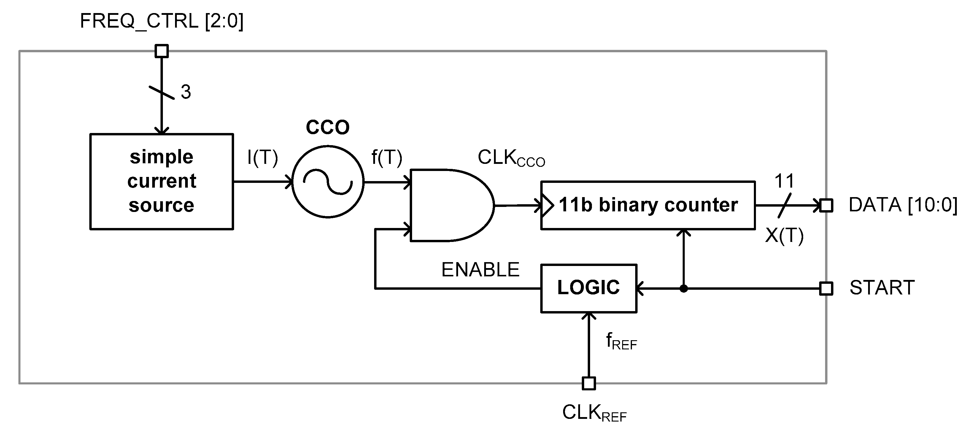
3.1. Architecture
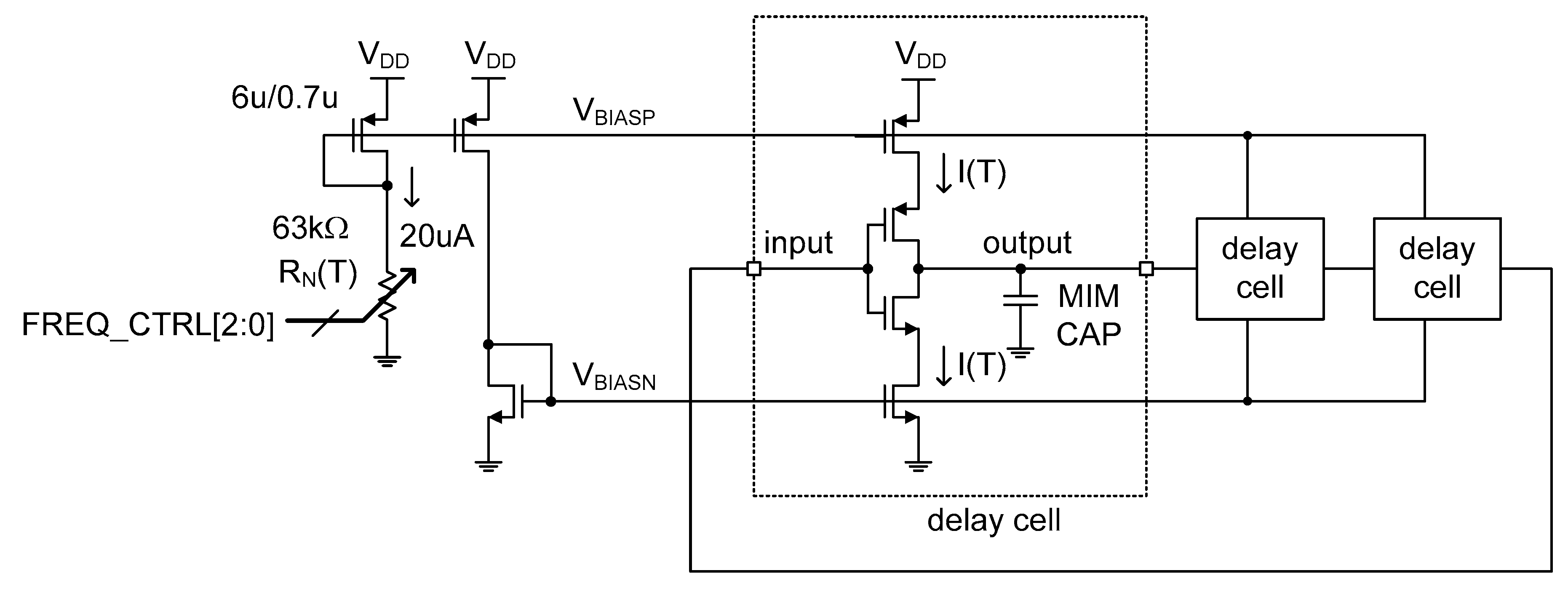
3.2. Circuits
4. Performance
5. Conclusions
Author Contributions
Funding
Acknowledgments
Conflicts of Interest
References
- Xu, Z.; Byun, S. A poly resistor based time domain CMOS temperature sensor with 9b SAR and fine delay line. Sensors 2020, 20, 2053. [Google Scholar] [CrossRef] [PubMed]
- Deng, F.; He, Y.; Li, B.; Zhang, L.; Wu, X.; Fu, Z. Design of an embedded CMOS temperature sensor for passive RFID tag chips. Sensors 2015, 15, 11442–11453. [Google Scholar] [CrossRef] [PubMed]
- Yang, W.; Jiang, H.; Wang, Z. A 0.0014 mm2 150 nW CMOS temperature sensor with nonlinearity characterization and calibration for the −60 to +40 °C measurement range. Sensors 2019, 19, 1777. [Google Scholar] [CrossRef] [PubMed]
- Ha, D.; Woo, K.; Meninger, S.; Xanthopoulos, T.; Crain, E.; Ham, D. Time-domain CMOS temperature sensors with dual delay-locked loops for microprocessor thermal monitoring. IEEE Trans. Very Large Scale Integr. (VLSI) Syst. 2012, 20, 1590–1601. [Google Scholar] [CrossRef]
- Chen, P.; Chen, C.-C.; Tsai, C.-C.; Lu, W.-F. A time-to-digital converter-based CMOS smart temperature sensor. IEEE J. Solid-State Circuits 2005, 40, 1642–1648. [Google Scholar] [CrossRef]
- Anand, T.; Makinwa, A.A.; Hanumolu, P.K. A VCO based highly digital temperature sensor with 0.034 °C/mV supply sensitivity. IEEE J. Solid-State Circuits 2016, 51, 2651–2663. [Google Scholar] [CrossRef]
- Someya, T.; Isam, A.K.M.M.; Sakurai, T.; Takamiya, M. An 11-nW CMOS temperature-to-digital converter utilizing sub-threshold current at sub-thermal drain voltage. IEEE J. Solid-State Circuits 2019, 54, 613–622. [Google Scholar] [CrossRef]
- Lin, Y.-S.; Sylvester, D.; Blaauw, D. An Ultra Low Power 1 V, 220 nW Temperature Sensor for Passive Wireless Applications. In Proceedings of the IEEE Custom Integrated Circuits Conference (CICC), San Jose, CA, USA, 21–24 September 2008; pp. 507–510. [Google Scholar]
- Jeong, S.; Foo, Z.; Lee, Y.; Sim, J.-Y.; Blaauw, D.; Sylvester, D. A fully-integrated 71 nW CMOS temperature sensor for low power wireless sensor nodes. IEEE J. Solid-State Circuits 2014, 49, 1682–1693. [Google Scholar] [CrossRef]
- Chen, C.-C.; Chen, C.-L.; Lin, Y.-T. Accurate behavioral simulator of all-digital time-domain smart temperature sensors by using SIMULINK. Sensors 2016, 16, 1256. [Google Scholar] [CrossRef]
- Kang, M.; Burm, J. Time-Domain Temperature Sensor Using Two Stage Vernier Type Time to digital Converter for Mobile Application. In Proceedings of the International SoC Design Conference (ISOCC), Jeju Island, Korea, 4–7 November 2012. [Google Scholar]
- Chen, P.; Chen, C.-C.; Peng, Y.-H.; Wang, K.-M.; Wang, Y.-S. A time-domain SAR smart temperature sensor with curvature compensation and a 3σ inaccuracy of −0.4 °C~+0.6 °C over a 0 °C to 90 °C range. IEEE J. Solid-State Circuits 2010, 45, 600–609. [Google Scholar] [CrossRef]
- Law, M.K.; Bermak, A. A 405-nW CMOS temperature sensor based on linear MOS operation. IEEE Trans. Circuits Syst. II Express Brief. 2009, 12, 891–895. [Google Scholar] [CrossRef]
- Tran, T.-H.; Peng, H.-W.; Chao, P.C.-P.; Hsieh, J.-W. A log-ppm digitally controlled crystal oscillator compensated by a new 0.19-mm2 time-domain temperature sensor. IEEE Sens. J. 2017, 17, 51–62. [Google Scholar] [CrossRef]
- Chen, C.-C.; Chen, C.-L.; Lin, Y. All-digital time-domain CMOS smart temperature sensor with on-chip linearity enhancement. Sensors 2016, 16, 176. [Google Scholar] [CrossRef] [PubMed]
- Chen, C.-C.; Lin, Y. A linearity-enhanced time-domain CMOS thermostat with process-variation calibration. Sensors 2014, 14, 18784–18799. [Google Scholar] [CrossRef]
- Chen, C.-C.; Chen, H.-W. A linearization time-domain CMOS smart temperature sensor using a curvature compensation oscillator. Sensors 2013, 13, 11439–11452. [Google Scholar] [CrossRef]
- Chen, C.-C.; Lin, S.-H. A time-domain CMOS oscillator-based thermostat with digital set-point programming. Sensors 2013, 13, 1679–1691. [Google Scholar] [CrossRef] [PubMed]
- Tang, Z.; Fang, Y.; Shi, Z.; Yu, X.-P.; Tan, N.N.; Pan, W. A 1770-μm2 leakage-based digital temperature sensor with supply sensitivity suppression in 55-nm CMOS. IEEE J. Solid-State Circuits 2020, 55, 781–793. [Google Scholar] [CrossRef]
- Ituero, P.; Lopez-Vallejo, M.; Lopez-Barrio, C. A 0.0016 mm2 0.64 nJ leakage-based CMOS temperature sensor. Sensors 2013, 13, 12648–12662. [Google Scholar] [CrossRef]
- Li, J.; Lin, Y.; Ye, S.; Wu, K.; Ning, N.; Yu, Q. A CMOS-thyristor based temperature sensor with +0.37 °C/−0.32 °C inaccuracy. Micromachines 2020, 11, 124. [Google Scholar] [CrossRef]
- Barajas, E.; Aragones, X.; Mateo, D.; Altet, J. Differential temperature sensor: Review of applications in the test and characterization of circuits, usage and design methodology. Sensors 2019, 19, 4815. [Google Scholar] [CrossRef]
- Chouhan, S.S.; Halonen, K. A 40 nW CMOS-based temperature sensor with calibration free inaccuracy within ±0.6 °C. Electronics 2019, 8, 1275. [Google Scholar] [CrossRef]
- Rao, S.; Pangallo, G.; Corte, F.G.D. Integrated amorphous silicon p-i-n temperature sensor for CMOS photonics. Sensors 2016, 16, 67. [Google Scholar] [CrossRef] [PubMed]
- Abarca, A.; Theuwissen, A. In-pixel temperature sensors with an accuracy of ±0.25 °C, a 3σ variation of ±0.7 °C in the spatial domain and a 3σ variation of ±1 °C in the temporal domain. Micromachines 2020, 11, 665. [Google Scholar] [CrossRef] [PubMed]
- Aparicio, H.; Ituero, P. A 900 μm2 BiCMOS temperature sensor for dynamic thermal management. Sensors 2020, 20, 3725. [Google Scholar] [CrossRef] [PubMed]
- Song, X.; Liu, H.; Fang, Y.; Zhao, C.; Qu, Z.; Wang, Q.; Tu, L.-C. An integrated gold-film temperature sensor for in situ temperature measurement of a high-precision MEMS accelerometer. Sensors 2020, 20, 3652. [Google Scholar] [CrossRef]
- Mey, G.D.; Kos, A. The influence of an additional sensor on the microprocessor temperature. Energies 2020, 13, 3156. [Google Scholar] [CrossRef]
- Root, W.; Bechtold, T.; Pham, T. Textile-integrated thermocouples for temperature measurement. Materials 2020, 13, 626. [Google Scholar] [CrossRef]
- Fu, C.; Ke, Y.; Li, M.; Luo, J.; Li, H.; Liang, G.; Fan, P. Design and implementation of 2.45GHz passive SAW temperature sensors with BPSK coded RFID configuration. Sensors 2017, 17, 1849. [Google Scholar] [CrossRef]


| Reference | [1] | [7] | [8] | [9] | [14] | This Work |
|---|---|---|---|---|---|---|
| CMOS technology | 0.18 μm | 0.18 μm | 0.18 μm | 0.18 μm | 0.18 μm | 0.18 μm |
| Die area | 0.432 mm2 | 0.074 mm2 | 0.05 mm2 | 0.09 mm2 | 0.19 mm2 | 0.026 mm2 |
| Supply voltage | 1.8 V | 0.8 V | 1.0 V | 1.2 V | 1.2 V | 1.8 V |
| Temperature range | 0–100 °C | −20–80 °C | 0–100 °C | 0–100 °C | −40–85 °C | 0–100 °C |
| Resolution | 0.49 °C | 0.145 °C | 0.3 °C | 0.3 °C | 0.18 °C | 0.32 °C |
| Accuracy | −1.6–0.6 °C | −0.9–1.2 °C | −1.6–3.0 °C | −1.4–1.5 °C | −1.0–1.0 °C | −1.0–0.7 °C |
| Conversion rate | 25 kHz | 1.2 Hz | 100 Hz | 33.3 Hz | 1kHz | 50 kHz |
| Energy efficiency | 7.2 nJ/sample | 8.9 nJ/sample | 2.2 nJ/sample | 2.2 nJ/sample | 66.5 nJ/sample | 1.4 nJ/sample |
| VDD sensitivity | 0.085 °C/mV | 0.0038 °C/mV | - | 0.014 °C/mV | - | 0.077 °C/mV |
© 2020 by the authors. Licensee MDPI, Basel, Switzerland. This article is an open access article distributed under the terms and conditions of the Creative Commons Attribution (CC BY) license (http://creativecommons.org/licenses/by/4.0/).
Share and Cite
Park, S.; Byun, S. A 0.026 mm2 Time Domain CMOS Temperature Sensor with Simple Current Source. Micromachines 2020, 11, 899. https://doi.org/10.3390/mi11100899
Park S, Byun S. A 0.026 mm2 Time Domain CMOS Temperature Sensor with Simple Current Source. Micromachines. 2020; 11(10):899. https://doi.org/10.3390/mi11100899
Chicago/Turabian StylePark, Sangwoo, and Sangjin Byun. 2020. "A 0.026 mm2 Time Domain CMOS Temperature Sensor with Simple Current Source" Micromachines 11, no. 10: 899. https://doi.org/10.3390/mi11100899
APA StylePark, S., & Byun, S. (2020). A 0.026 mm2 Time Domain CMOS Temperature Sensor with Simple Current Source. Micromachines, 11(10), 899. https://doi.org/10.3390/mi11100899