Fabrication of Different Microchannels by Adjusting the Extrusion Parameters for Sacrificial Molds


 ,
,  and
and 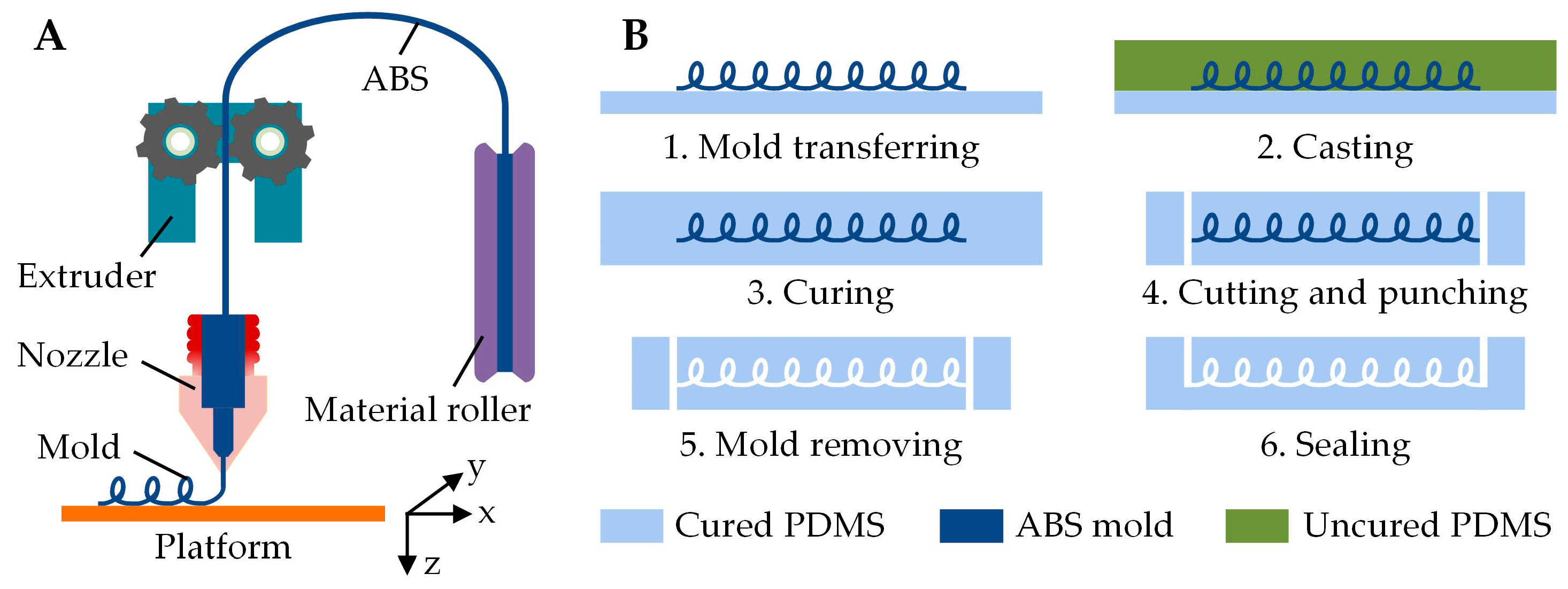
Abstract
1. Introduction
2. Materials and Methods
2.1. Microchannel Fabrication
2.2. Microchannel Characterization
3. Results and Discussion
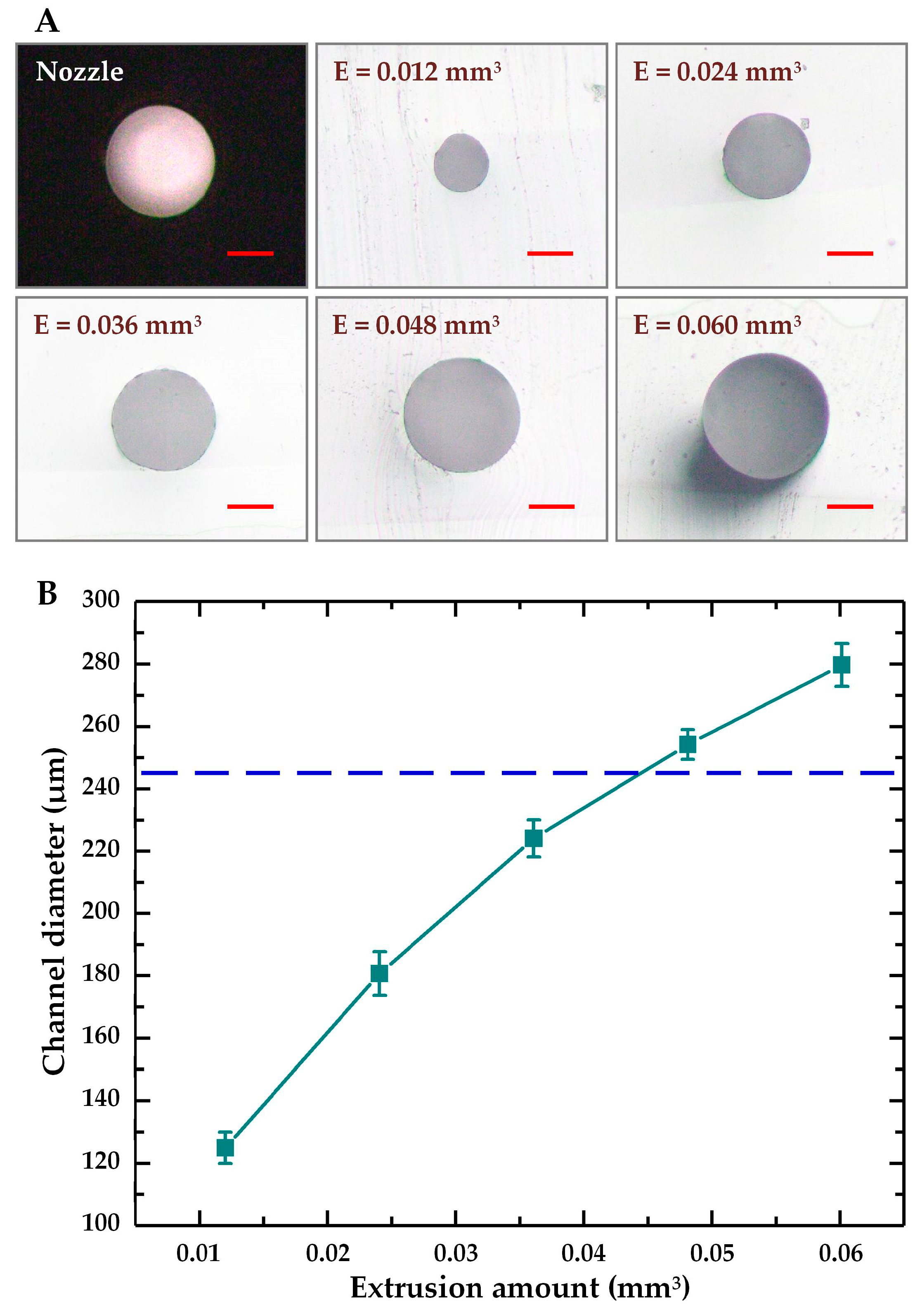
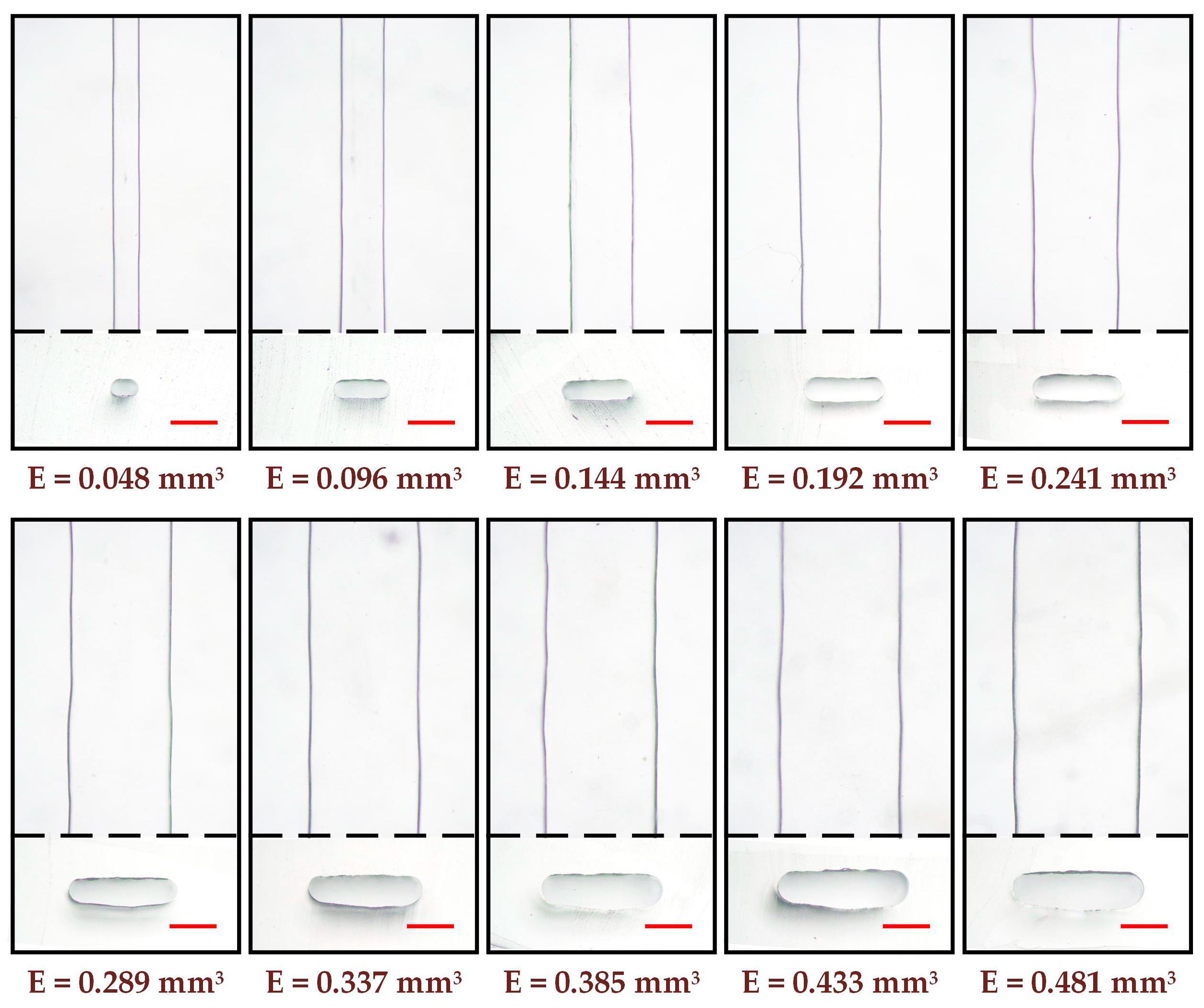
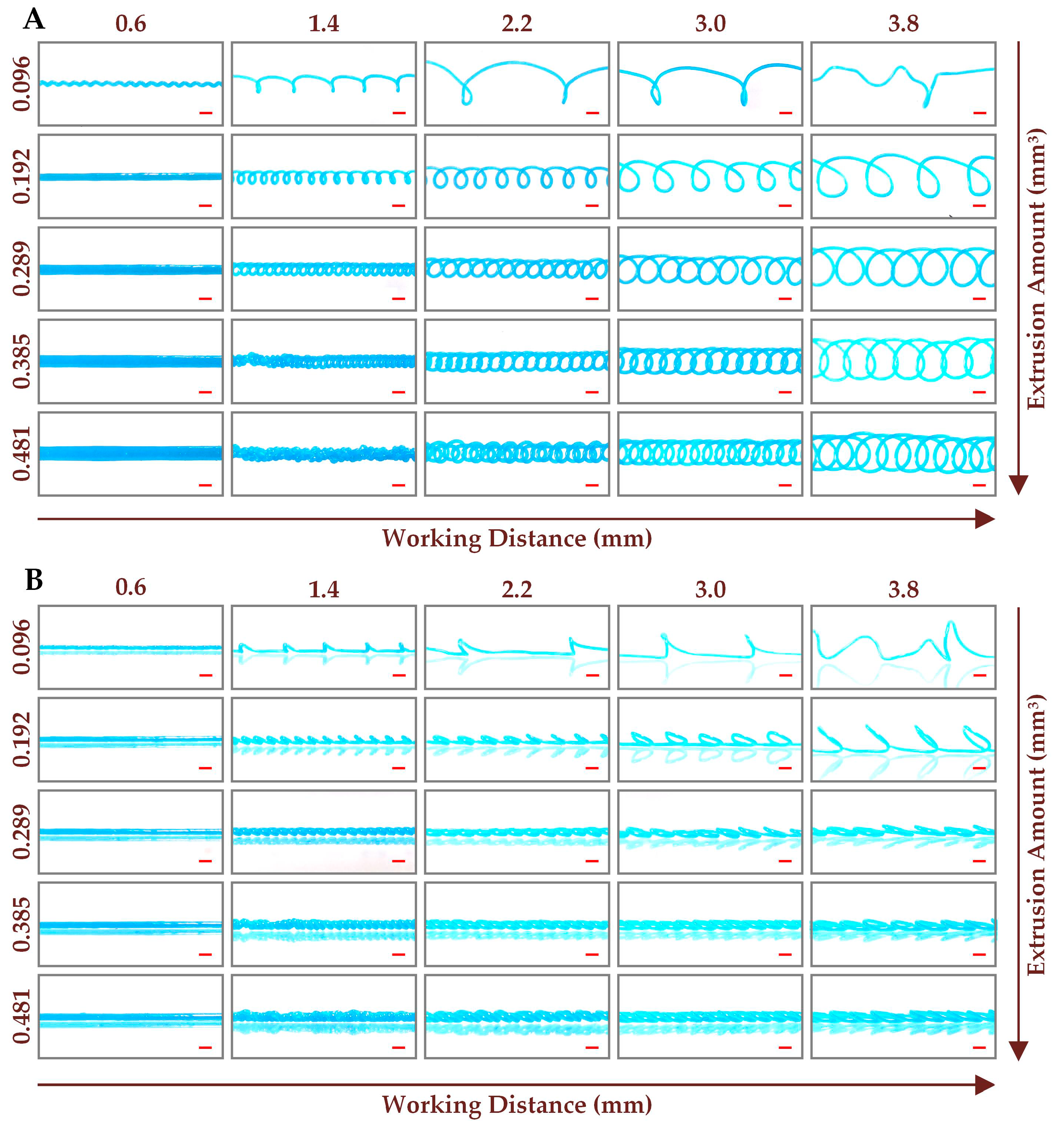
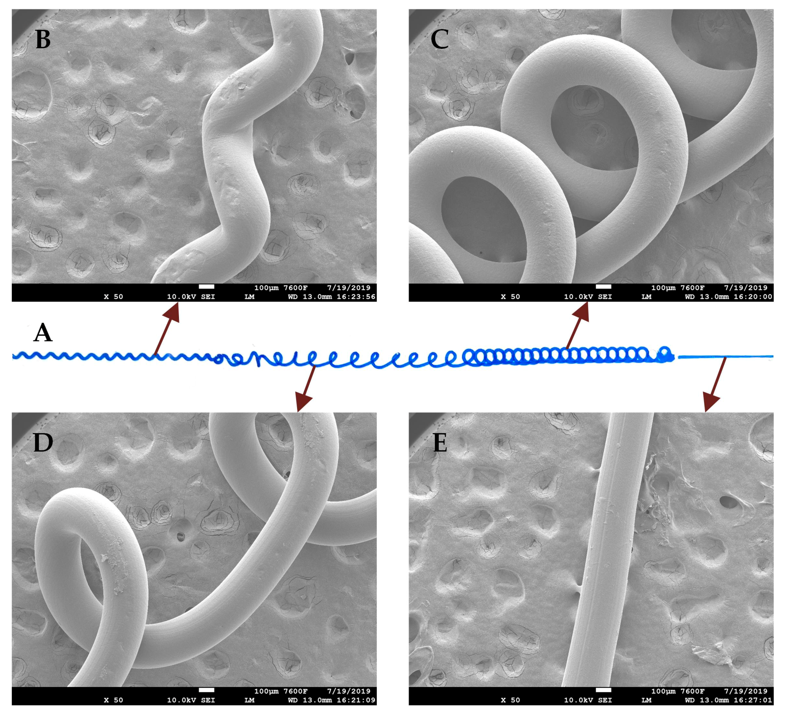
3.1. Fabrication of Straight Microchannel
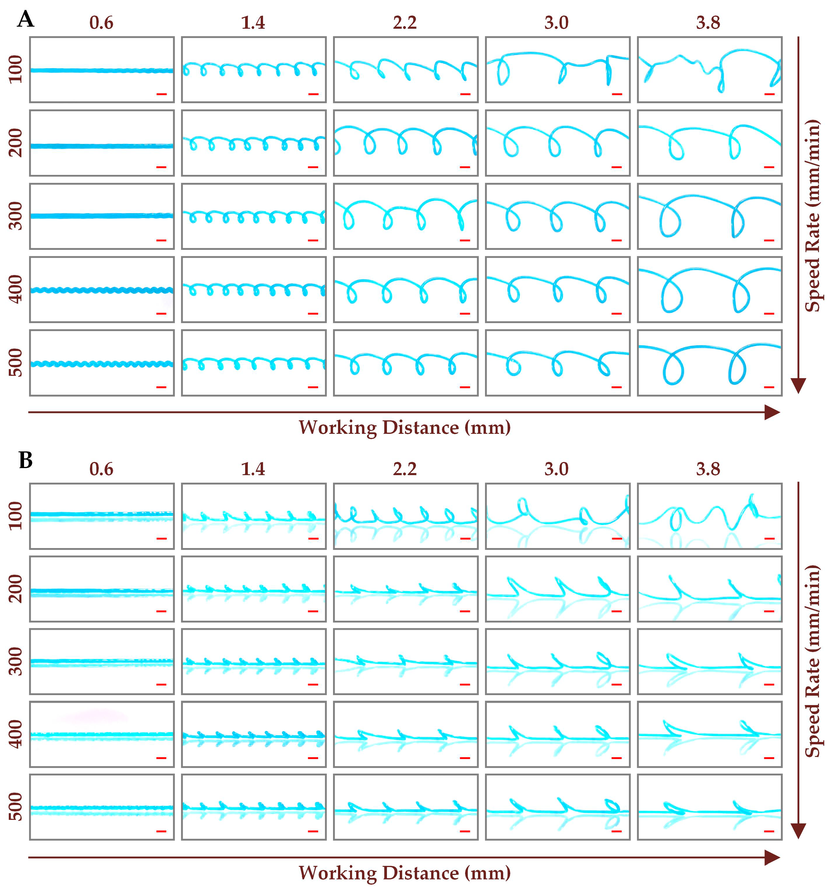
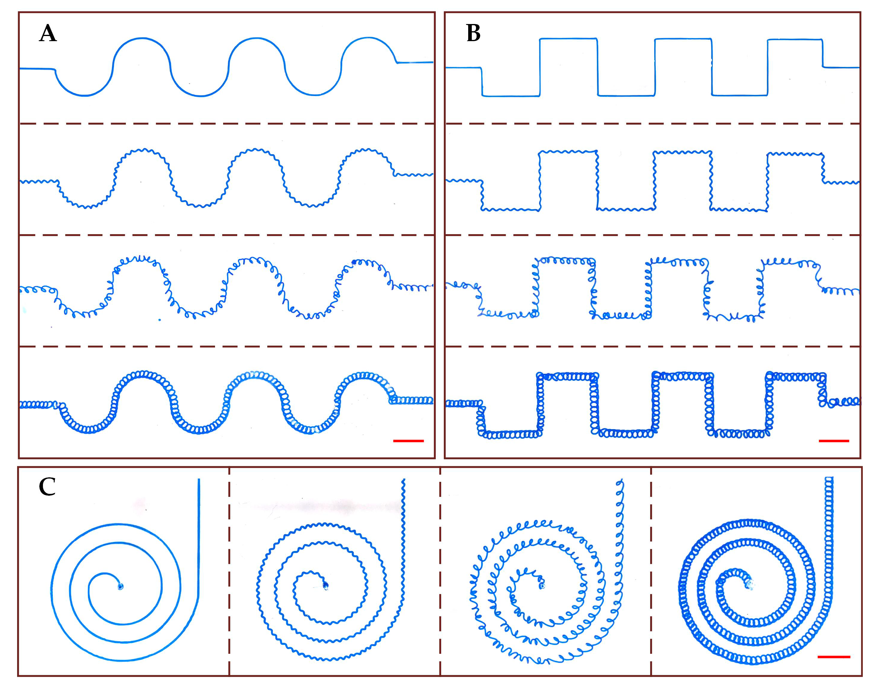
3.2. Fabrication of Curved Microchannel
3.3. Fabrication of Complex Microchannel
4. Conclusions
Author Contributions
Funding
Acknowledgments
Conflicts of Interest
References
- Whitesides, G.M. The origins and the future of microfluidics. Nature 2006, 442, 368–373. [Google Scholar] [CrossRef]
- Rothbauer, M.; Zirath, H.; Ertl, P. Recent advances in microfluidic technologies for cell-to-cell interaction studies. Lab Chip 2018, 18, 249–270. [Google Scholar] [CrossRef]
- Gorkin, R.; Park, J.; Siegrist, J.; Amasia, M.; Lee, B.S.; Park, J.M.; Kim, J.; Kim, H.; Madou, M.; Cho, Y.K. Centrifugal microfluidics for biomedical applications. Lab Chip 2010, 10, 1758–1773. [Google Scholar] [CrossRef]
- Elvira, K.S.; Solvas, X.C.I.; Wootton, R.C.R.; deMello, A.J. The past, present and potential for microfluidic reactor technology in chemical synthesis. Nat. Chem. 2013, 5, 905–915. [Google Scholar] [CrossRef]
- Meredith, N.A.; Quinn, C.; Cate, D.M.; Reilly, T.H.; Volckens, J.; Henry, C.S. Paper-based analytical devices for environmental analysis. Analyst 2016, 141, 1874–1887. [Google Scholar] [CrossRef]
- Chen, W.; Lam, R.H.W.; Fu, J. Photolithographic surface micromachining of polydimethylsiloxane (PDMS). Lab Chip 2012, 12, 391–395. [Google Scholar] [CrossRef]
- Deng, Y.; Yi, P.; Peng, L.; Lai, X.; Lin, Z. Experimental investigation on the large-area fabrication of micro-pyramid arrays by roll-to-roll hot embossing on PVC film. J. Micromech. Microeng. 2014, 24, 045023. [Google Scholar] [CrossRef]
- Hong, T.-F.; Ju, W.-J.; Wu, M.-C.; Tai, C.-H.; Tsai, C.-H.; Fu, L.-M. Rapid prototyping of PMMA microfluidic chips utilizing a CO2 laser. Microfluid. Nanofluid. 2010, 9, 1125–1133. [Google Scholar] [CrossRef]
- Tian, F.; Cai, L.; Chang, J.; Li, S.; Liu, C.; Li, T.; Sun, J. Label-free isolation of rare tumor cells from untreated whole blood by interfacial viscoelastic microfluidics. Lab Chip 2018, 18, 3436–3445. [Google Scholar] [CrossRef]
- Duffy, D.C.; McDonald, J.C.; Schueller, O.J.A.; Whitesides, G.M. Rapid prototyping of microfluidic systems in poly(dimethylsiloxane). Anal. Chem. 1998, 70, 4974–4984. [Google Scholar] [CrossRef]
- Sochol, R.D.; Sweet, E.; Glick, C.C.; Wu, S.-Y.; Yang, C.; Restaino, M.; Lin, L. 3D printed microfluidics and microelectronics. Microelectron. Eng. 2018, 189, 52–68. [Google Scholar] [CrossRef]
- Pranzo, D.; Larizza, P.; Filippini, D.; Percoco, G. Extrusion-based 3D printing of microfluidic devices for chemical and biomedical applications: A topical review. Micromachines 2018, 9, 374. [Google Scholar] [CrossRef]
- Therriault, D.; White, S.R.; Lewis, J.A. Chaotic mixing in three-dimensional microvascular networks fabricated by direct-write assembly. Nat. Mater. 2003, 2, 265–271. [Google Scholar] [CrossRef]
- Bhargava, K.C.; Thompson, B.; Malmstadt, N. Discrete elements for 3D microfluidics. Proc. Natl. Acad. Sci. USA 2014, 111, 15013–15018. [Google Scholar] [CrossRef]
- Sochol, R.D.; Sweet, E.; Glick, C.C.; Venkatesh, S.; Avetisyan, A.; Ekman, K.F.; Raulinaitis, A.; Tsai, A.; Wienkers, A.; Korner, K.; et al. 3D printed microfluidic circuitry via multijet-based additive manufacturing. Lab Chip 2016, 16, 668–678. [Google Scholar] [CrossRef]
- Mohamed, M.G.A.; Kumar, H.; Wang, Z.; Martin, N.; Mills, B.; Kim, K. Rapid and inexpensive fabrication of multi-depth microfluidic device using high-resolution LCD stereolithographic 3D printing. J. Manuf. Mater. Process. 2019, 3, 26. [Google Scholar] [CrossRef]
- McDonald, J.C.; Chabinyc, M.L.; Metallo, S.J.; Anderson, J.R.; Stroock, A.D.; Whitesides, G.M. Prototyping of microfluidic devices in poly(dimethylsiloxane) using solid-object printing. Anal. Chem. 2002, 74, 1537–1545. [Google Scholar] [CrossRef]
- Comina, G.; Suska, A.; Filippini, D. Low cost lab-on-a-chip prototyping with a consumer grade 3D printer. Lab Chip 2014, 14, 2978–2982. [Google Scholar] [CrossRef]
- Saggiomo, V.; Velders, A.H. Simple 3D printed scaffold-removal method for the fabrication of intricate microfluidic devices. Adv. Sci. 2015, 2, 1500125. [Google Scholar] [CrossRef]
- Goh, W.H.; Hashimoto, M. Dual sacrificial molding: Fabricating 3D microchannels with overhang and helical features. Micromachines 2018, 9, 523. [Google Scholar] [CrossRef]
- Goh, W.H.; Hashimoto, M. Fabrication of 3D microfluidic channels and in-channel features using 3D printed, water-soluble sacrificial mold. Macromol. Mater. Eng. 2018, 303, 1700484. [Google Scholar] [CrossRef]
- Dahlberg, T.; Stangner, T.; Zhang, H.; Wiklund, K.; Lundberg, P.; Edman, L.; Andersson, M. 3D printed water-soluble scaffolds for rapid production of PDMS micro-fluidic flow chambers. Sci. Rep. 2018, 8, 3372. [Google Scholar] [CrossRef]
- Yang, W.; Zhu, T.; Jin, Y.; Fu, J. Facile fabrication of helical microfluidic channel based on rope coiling effect. Microsyst. Technol. 2017, 23, 2957–2964. [Google Scholar] [CrossRef]
- Tang, W.; Fan, N.; Yang, J.; Li, Z.; Zhu, L.; Jiang, D.; Shi, J.; Xiang, N. Elasto-inertial particle focusing in 3D-printed microchannels with unconventional cross sections. Microfluid. Nanofluid. 2019, 23, 42. [Google Scholar] [CrossRef]
- Tang, W.; Fan, N.; Li, Z.; Xiang, N.; Yang, J. Facile fabrication of microchannel with unconventional cross-section using 3D printed sacrificial mould. Chin. J. Anal. Chem. 2019, 47, 838–845. [Google Scholar]
- Choi, C.-H.; Yi, H.; Hwang, S.; Weitz, D.A.; Lee, C.-S. Microfluidic fabrication of complex-shaped microfibers by liquid template-aided multiphase microflow. Lab Chip 2011, 11, 1477–1483. [Google Scholar] [CrossRef]
- Zhang, J.; Yan, S.; Yuan, D.; Alici, G.; Nguyen, N.T.; Warkiani, M.E.; Li, W.H. Fundamentals and applications of inertial microfluidics: A review. Lab Chip 2016, 16, 10–34. [Google Scholar] [CrossRef]
- Özkan, A.; Erdem, E.Y. Numerical analysis of mixing performance in sinusoidal microchannels based on particle motion in droplets. Microfluid. Nanofluid. 2015, 19, 1101–1108. [Google Scholar] [CrossRef]
- Paiè, P.; Bragheri, F.; Di Carlo, D.; Osellame, R. Particle focusing by 3D inertial microfluidics. Microsyst. Nanoeng. 2017, 3, 17027. [Google Scholar] [CrossRef]
- Liu, K.; Yang, Q.; Chen, F.; Zhao, Y.; Meng, X.; Shan, C.; Li, Y. Design and analysis of the cross-linked dual helical micromixer for rapid mixing at low Reynolds numbers. Microfluid. Nanofluid. 2015, 19, 169–180. [Google Scholar] [CrossRef]


© 2019 by the authors. Licensee MDPI, Basel, Switzerland. This article is an open access article distributed under the terms and conditions of the Creative Commons Attribution (CC BY) license (http://creativecommons.org/licenses/by/4.0/).
Share and Cite
Tang, W.; Liu, H.; Zhu, L.; Shi, J.; Li, Z.; Xiang, N.; Yang, J. Fabrication of Different Microchannels by Adjusting the Extrusion Parameters for Sacrificial Molds. Micromachines 2019, 10, 544. https://doi.org/10.3390/mi10080544
Tang W, Liu H, Zhu L, Shi J, Li Z, Xiang N, Yang J. Fabrication of Different Microchannels by Adjusting the Extrusion Parameters for Sacrificial Molds. Micromachines. 2019; 10(8):544. https://doi.org/10.3390/mi10080544
Chicago/Turabian StyleTang, Wenlai, Hao Liu, Liya Zhu, Jianping Shi, Zongan Li, Nan Xiang, and Jiquan Yang. 2019. "Fabrication of Different Microchannels by Adjusting the Extrusion Parameters for Sacrificial Molds" Micromachines 10, no. 8: 544. https://doi.org/10.3390/mi10080544
APA StyleTang, W., Liu, H., Zhu, L., Shi, J., Li, Z., Xiang, N., & Yang, J. (2019). Fabrication of Different Microchannels by Adjusting the Extrusion Parameters for Sacrificial Molds. Micromachines, 10(8), 544. https://doi.org/10.3390/mi10080544