Towards a Miniaturized 3D Receiver WPT System for Capsule Endoscopy


Abstract
1. Introduction
2. Full Characterization of the 3D RX Coils System
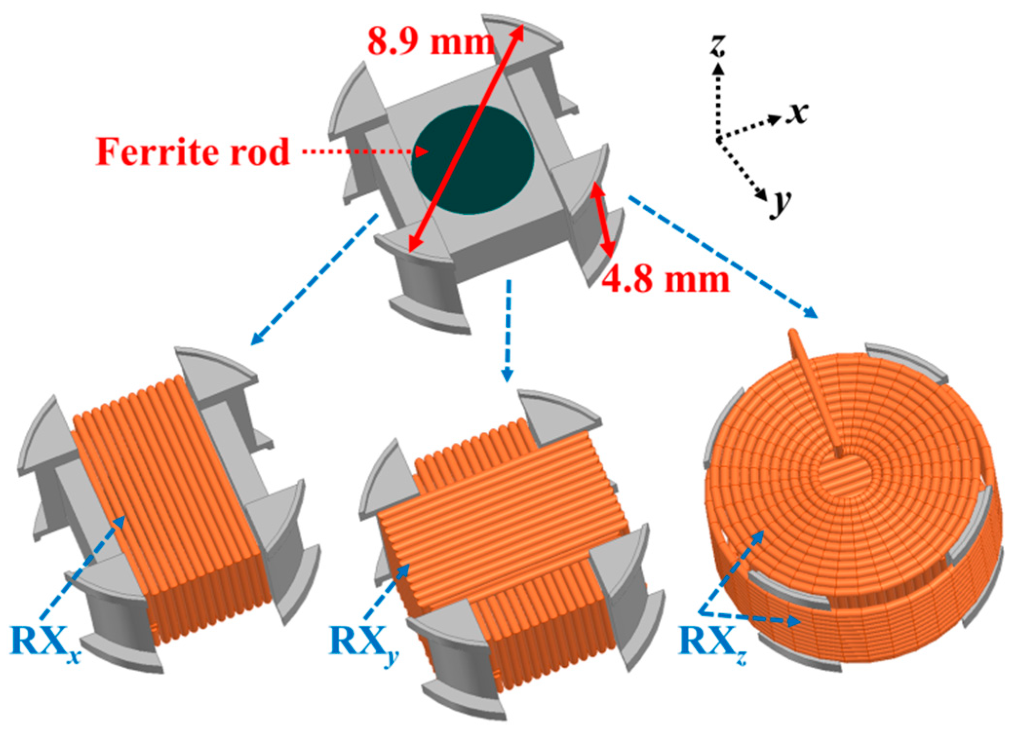
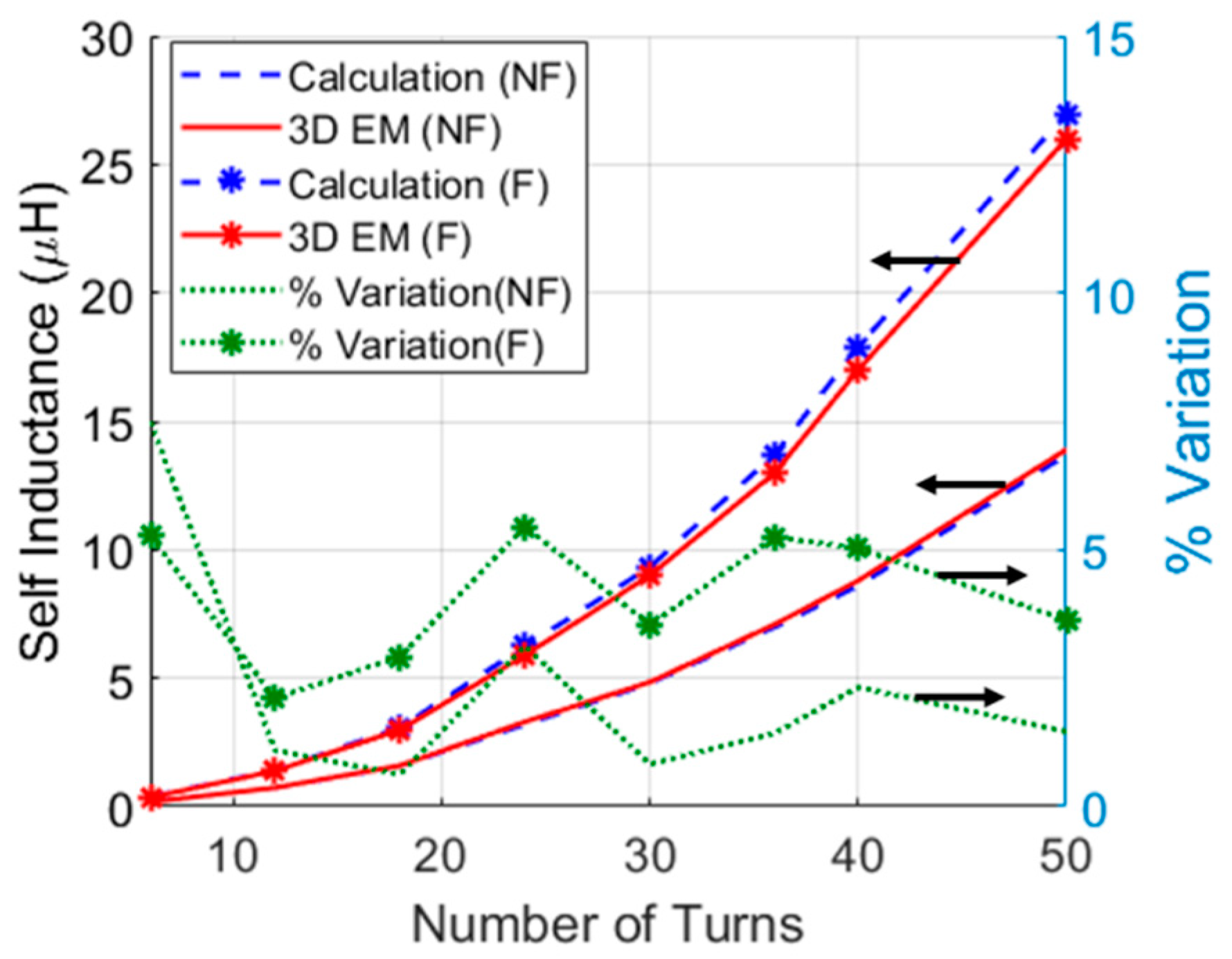
2.1. Derivation of the Self-Inductance of the 3D RX Coil’s Structure
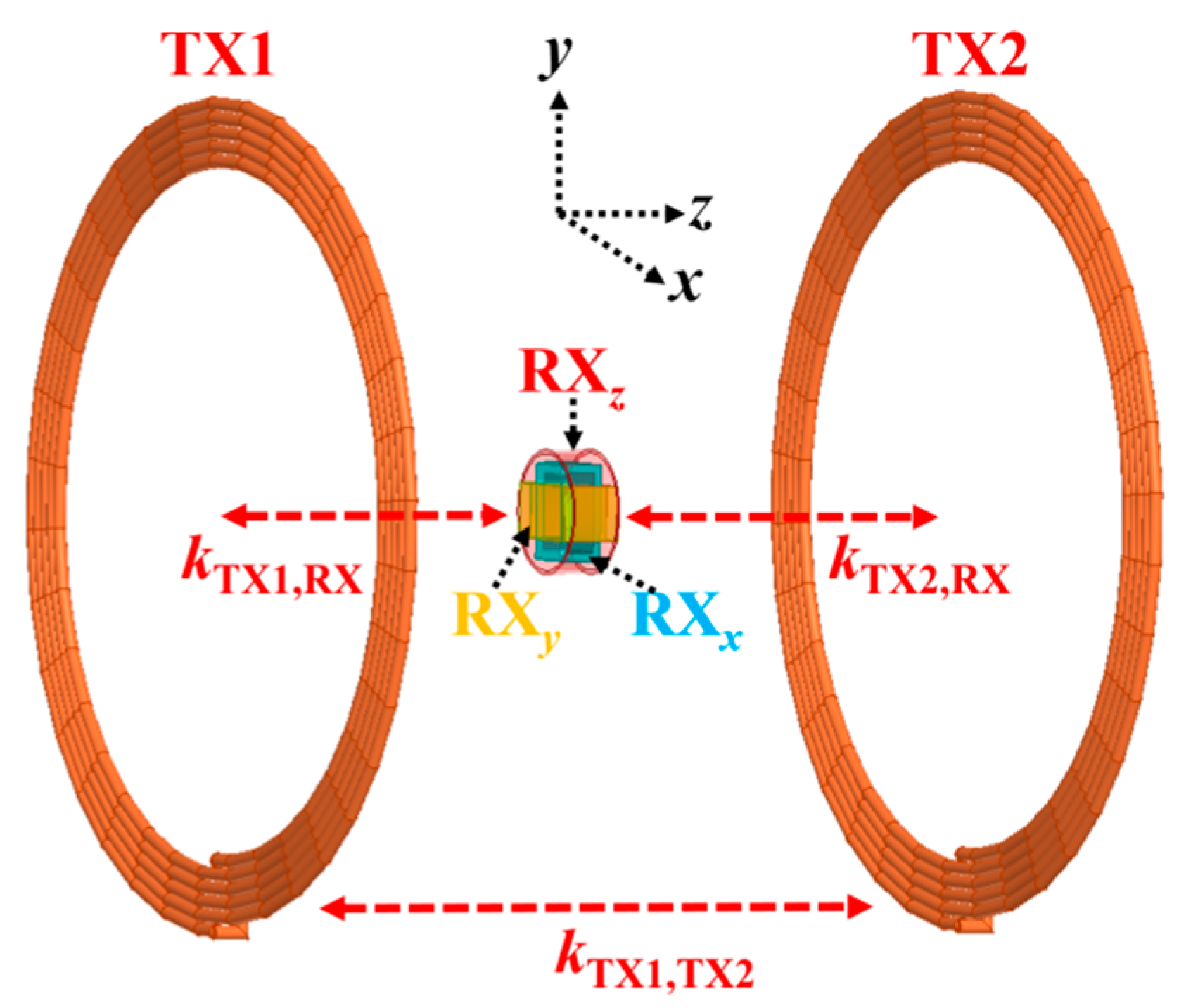
2.2. Derivation of the Mutual Inductance of the 3D RX Coil’s Structure
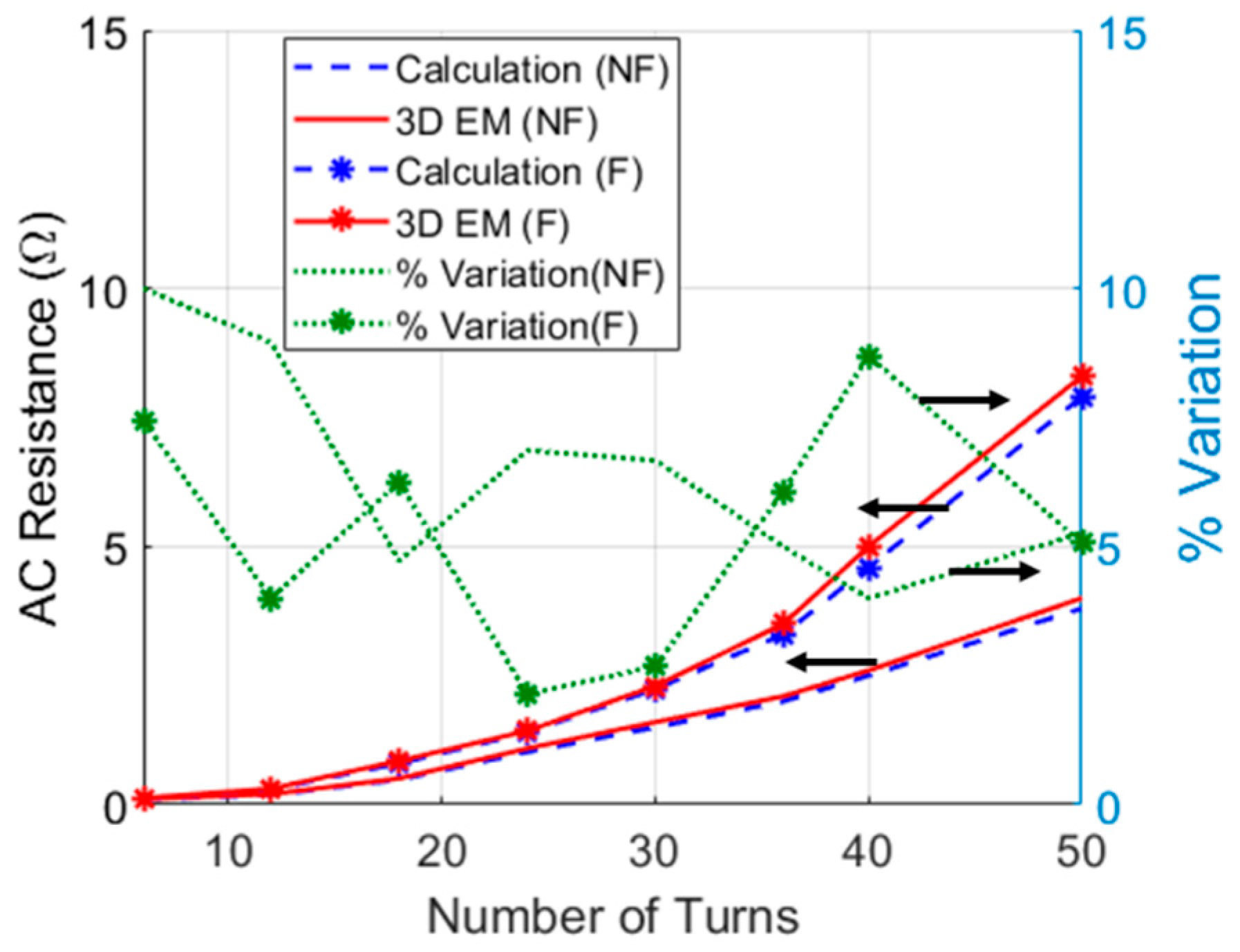
2.3. AC Resistance of the WPT Coil
3. Optimization of the Multi-TX and 3D RX System
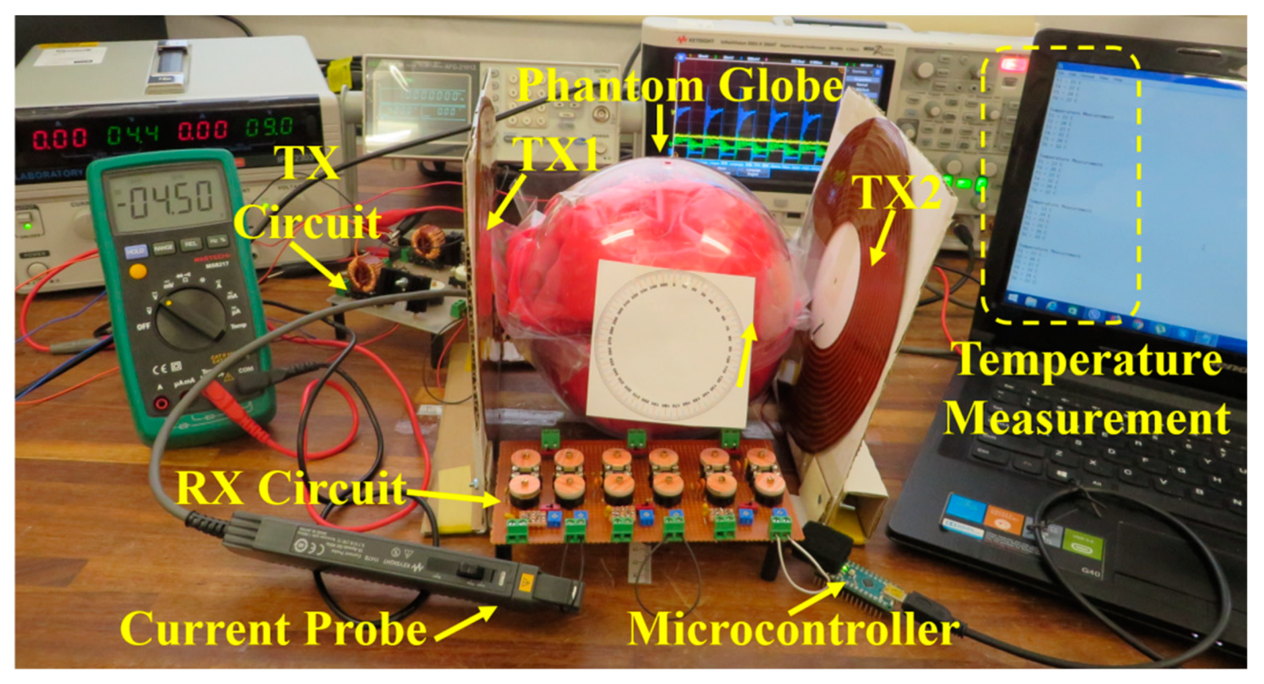
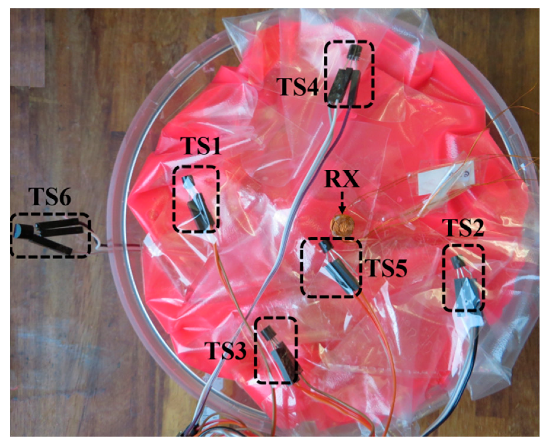
4. Experimental Setup
5. Results and Discussion
6. Conclusions
Author Contributions
Funding
Conflicts of Interest
References
- Iddan, G.; Meron, G.; Glukhovsky, A.; Swain, P. Wireless capsule endoscopy. Nature 2000, 405, 417. [Google Scholar] [CrossRef] [PubMed]
- Kong, K.C.; Cha, J.; Jeon, D.; Cho, D.I.D. A rotational micro biopsy device for the capsule endoscope. In Proceedings of the 2005 IEEE/RSJ International Conference on Intelligent Robots and Systems, Edmonton, AB, Canada, 2–6 August 2005; pp. 1839–1843. [Google Scholar]
- Park, S.; Koo, K.-I.; Kim, G.-S.; Bang, S.M.; Song, S.Y.; Byun, J.-W.; Chu, C.-N.; Cho, D. “Dan” A Novel Micro-Biopsy Actuator for Capsular Endoscope using LIGA Process. In Proceedings of the TRANSDUCERS 2007-2007 International Solid-State Sensors, Actuators and Microsystems Conference, Lyon, France, 10–14 June 2007; pp. 209–212. [Google Scholar]
- Shao, Q.; Liu, H.; Li, H.; Yang, Y. Miniature pH sensor for capsule endoscopy with composite diagnosis. In Proceedings of the IEEE SENSORS 2014 Proceedings, Valencia, Spain, 2–5 November 2014; pp. 339–342. [Google Scholar]
- Cummins, G.; Cox, B.F.; Ciuti, G.; Anbarasan, T.; Desmulliez, M.P.Y.; Cochran, S.; Steele, R.; Plevris, J.N.; Koulaouzidis, A. Gastrointestinal diagnosis using non-white light imaging capsule endoscopy. Nat. Rev. Gastroenterol. Hepatol. 2019, 16, 429–447. [Google Scholar] [CrossRef] [PubMed]
- Sungwook Yang, S.; Kitae Park, K.; Jinseok Kim, J.; Tae Song Kim, T.S.; Il-Joo Cho, I.-J.; Eui-Sung Yoon, E.-S. Autonomous locomotion of capsule endoscope in gastrointestinal tract. In Proceedings of the 2011 Annual International Conference of the IEEE Engineering in Medicine and Biology Society, Boston, MA, USA, 30 August–3 September 2011; Volume 2011, pp. 6659–6663. [Google Scholar]
- Faerber, J.; Cummins, G.; Pavuluri, S.K.; Record, P.; Rodriguez, A.R.A.; Lay, H.S.; McPhillips, R.; Cox, B.F.; Connor, C.; Gregson, R.; et al. In Vivo Characterization of a Wireless Telemetry Module for a Capsule Endoscopy System Utilizing a Conformal Antenna. IEEE Trans. Biomed. Circuits Syst. 2017, 12, 95–105. [Google Scholar] [CrossRef] [PubMed]
- Carta, R.; Sfakiotakis, M.; Pateromichelakis, N.; Thoné, J.; Tsakiris, D.P.; Puers, R. A multi-coil inductive powering system for an endoscopic capsule with vibratory actuation. Sens. Actuators A Phys. 2011, 172, 253–258. [Google Scholar] [CrossRef]
- Bingquan, Z.; Guozheng, Y.; Zhiwei, J.; Yu, S. Portable Wireless Power Transmission System of a Video Capsule Endoscopy: Design and Realization. In Proceedings of the 2012 International Conference on Biomedical Engineering and Biotechnology, Macao, China, 28–30 May 2012; pp. 409–412. [Google Scholar]
- Reza Khan, S.; Choi, G. Optimization of planar strongly coupled wireless power transfer system for biomedical applications. Microw. Opt. Technol. Lett. 2016, 58, 1861–1866. [Google Scholar] [CrossRef]
- Khan, S.R.; Choi, G.S. Analysis and optimization of four-coil planar magnetically coupled printed spiral resonators. Sensors (Switzerland) 2016, 16, 1219. [Google Scholar] [CrossRef] [PubMed]
- Silay, K.M.; Dehollain, C.; Declercq, M. A Closed-Loop Remote Powering Link for Wireless Cortical Implants. IEEE Sens. J. 2013, 13, 3226–3235. [Google Scholar] [CrossRef]
- Zhang, X.; Ho, S.L.; Fu, W.N. A Hybrid Optimal Design Strategy of Wireless Magnetic-Resonant Charger for Deep Brain Stimulation Devices. IEEE Trans. Magn. 2013, 49, 2145–2148. [Google Scholar] [CrossRef]
- Jegadeesan, R.; Nag, S.; Agarwal, K.; Thakor, N.V.; Guo, Y.X. Enabling Wireless powering and telemetry for peripheral nerve implants. IEEE J. Biomed. Health Inform. 2015, 19, 958–970. [Google Scholar] [CrossRef]
- Wang, J.; Leach, M.; Lim, E.G.; Wang, Z.; Pei, R.; Huang, Y. An Implantable and Conformal Antenna for Wireless Capsule Endoscopy. IEEE Antennas Wirel. Propag. Lett. 2018, 17, 1153–1157. [Google Scholar] [CrossRef]
- Jonah, O.; Georgakopoulos, S.V.; Tentzeris, M.M. Orientation insensitive power transfer by magnetic resonance for mobile devices. In Proceedings of the 2013 IEEE Wireless Power Transfer (WPT), Perugia, Italy, 15–16 May 2013; pp. 5–8. [Google Scholar]
- Liu, D.; Hu, H.; Georgakopoulos, S. Misalignment Sensitivity of Strongly Coupled Wireless Power Transfer Systems. IEEE Trans. Power Electron. 2016, 32, 5509–5519. [Google Scholar] [CrossRef]
- Jia, Y.; Mirbozorgi, S.A.; Wang, Z.; Hsu, C.C.; Madsen, T.E.; Rainnie, D.; Ghovanloo, M. Position and orientation insensitive wireless power transmission for enerCage-homecage system. IEEE Trans. Biomed. Eng. 2017, 64, 2439–2449. [Google Scholar] [CrossRef] [PubMed]
- Lenaerts, B.; Puers, R. An inductive power link for a wireless endoscope. Biosens. Bioelectron. 2007, 22, 1390–1395. [Google Scholar] [CrossRef] [PubMed]
- Zhiwei, J.; Guozheng, Y.; Jiangpingping; Zhiwu, W.; Hua, L. Efficiency optimization of wireless power transmission systems for active capsule endoscopes. Physiol. Meas. 2011, 32, 1561–1573. [Google Scholar] [CrossRef] [PubMed]
- Bocan, K.N.; Mickle, M.H.; Sejdic, E. Multi-Disciplinary Challenges in Tissue Modeling for Wireless Electromagnetic Powering: A Review. IEEE Sens. J. 2017, 17, 6498–6509. [Google Scholar] [CrossRef]
- Pacini, A.; Benassi, F.; Masotti, D.; Costanzo, A. Design of a RF-to-dc Link for in-body IR-WPT with a Capsule-shaped Rotation-insensitive Receiver. In Proceedings of the 2018 IEEE/MTT-S International Microwave Symposium-IMS, Philadelphia, PA, USA, 10–15 June 2018; pp. 1289–1292. [Google Scholar]
- Khan, S.R.; Pavuluri, S.K.; Desmulliez, M.P.Y. New Analytical Model for the Characterisation of Printed Spiral Coils for Wireless Power Transfer. In Proceedings of the IEEE 12th European Conference on Antennas and Propagation (EuCAP), London, UK, 9–13 April 2018. [Google Scholar]
- Theilmann, P.T.; Asbeck, P.M. An analytical model for inductively coupled implantable biomedical devices with ferrite rods. IEEE Trans. Biomed. Circuits Syst. 2009, 3, 43–52. [Google Scholar] [CrossRef] [PubMed]
- Khan, S.R.; Pavuluri, S.K.; Desmulliez, M.P.Y. Accurate Modeling of Coil Inductance for Near-Field Wireless Power Transfer. IEEE Trans. Microw. Theory Tech. 2018, 66, 4158–4169. [Google Scholar] [CrossRef]
- Kiani, M.; Jow, U.M.; Ghovanloo, M. Design and Optimization of a 3 Coil Inductive Link for Efficient Wireless Power Transmission. IEEE Trans. Biomed. Circuits Syst. 2011, 5, 579–591. [Google Scholar] [CrossRef]
- Kiani, M.; Ghovanloo, M. A figure-of-merit for designing high-performance inductive power transmission links. IEEE Trans. Ind. Electron. 2013, 60, 5292–5305. [Google Scholar] [CrossRef]
- Kim, J.; Park, Y.J. Approximate Closed-Form Formula for Calculating Ohmic Resistance in Coils of Parallel Round Wires with Unequal Pitches. IEEE Trans. Ind. Electron. 2015, 62, 3482–3489. [Google Scholar]
- Wheeler, H.A. Formulas for the Skin Effect. Proc. IRE 1942, 30, 299–311. [Google Scholar] [CrossRef]
- Kamidaki, C.; Guan, N. Theoretical Analysis of AC Resistance of Coil Made by Copper Clad Aluminum Wires. In Proceedings of the Progress in Electromagnetics Research Symposium Proceedings, Stockholm, Sweden, 12–15 August 2013; pp. 1730–1734. [Google Scholar]
- Sullivan, C.R. Aluminum windings and other strategies for high-frequency magnetics design in an era of high copper and energy costs. IEEE Trans. Power Electron. 2008, 23, 2044–2051. [Google Scholar] [CrossRef]
- Stratton, J.A. Electromagnetic Theory; Wiley: New York, NY, USA, 2007; (republication of original 1941 McGraw-Hill edition). [Google Scholar]
- Yang, Z.; Liu, W.; Basham, E. Inductor modeling in wireless links for implantable electronics. IEEE Trans. Magn. 2007, 43, 3851–3860. [Google Scholar] [CrossRef]
- Kurs, A.; Karalis, A.; Moffatt, R.; Joannopoulos, J.D.; Fisher, P.; Soljacic, M. Wireless Power Transfer via Strongly Coupled Magnetic Resonances. Science 2007, 317, 83–86. [Google Scholar] [CrossRef] [PubMed]
- Kiani, M.; Ghovanloo, M. The circuit theory behind coupled-mode magnetic resonance-based wireless power transmission. IEEE Trans. Circuits Syst. I Regul. Pap. 2012, 59, 2065–2074. [Google Scholar] [CrossRef] [PubMed]
- Lay, H.; Cummins, G.; Cox, B.F.; Qiu, Y.; Turcanu, M.V.; McPhillips, R.; Connor, C.; Gregson, R.; Clutton, E.; Desmulliez, M.P.Y.; et al. In-Vivo Evaluation of Microultrasound and Thermometric Capsule Endoscopes. IEEE Trans. Biomed. Eng. 2018, 66, 632–639. [Google Scholar] [CrossRef]
- Khan, S.R.; Pavuluri, S.K.; Cummins, G.; Desmulliez, M.P.Y. Miniaturized 3D Cross-Type Receiver for Wirelessly Powered Capsule Endoscopy. IEEE Trans. Microw. Theory Tech. 2019, 67, 1985–1993. [Google Scholar] [CrossRef]
- Na, K.; Jang, H.; Ma, H.; Bien, F. Tracking optimal efficiency of magnetic resonance wireless power transfer system for biomedical capsule endoscopy. IEEE Trans. Microw. Theory Tech. 2015, 63, 295–303. [Google Scholar] [CrossRef]
- Ding, K.; Yu, Y.; Lin, H.; Xie, J. Wireless Power Transfer at Sub-GHz frequency for Capsule Endoscope. Prog. Electromagn. Res. C 2016, 66, 55–61. [Google Scholar] [CrossRef]
- Acar, M.; Annema, A.J.; Nauta, B. Generalized design equations for Class-E power amplifiers with finite DC feed inductance. In Proceedings of the 36th European Microwave Conference, Manchester, UK, 10–15 September 2006; pp. 1308–1311. [Google Scholar]
- Liu, H.; Shao, Q.; Fang, X. Modeling and Optimization of Class-E Amplifier at Subnominal Condition in a Wireless Power Transfer System for Biomedical Implants. IEEE Trans. Biomed. Circuits Syst. 2017, 11, 35–43. [Google Scholar] [CrossRef]
- Ping, S.; Hu, A.P. Analyses of DC Inductance Used in ICPT Power Pick-Ups for Maximum Power Transfer. In Proceedings of the 2005 IEEE/PES Transmission & Distribution Conference & Exposition: Asia and Pacific, Dalian, China, 18 August 2005; pp. 1–6. [Google Scholar]
- Basar, M.R.; Yazed, M.; Cho, J.; Ibrahim, F. A Wireless Power Transmission System for Robotic Capsule Endoscopy: Design and Optimization. In Proceedings of the 2014 IEEE MTT-S International Microwave Workshop Series on RF and Wireless Technologies for Biomedical and Healthcare Applications (IMWS-Bio2014), London, UK, 8–10 December 2014; pp. 2–4. [Google Scholar]
- Singeap, A.M.; Stanciu, C.; Trifan, A. Capsule endoscopy: The road ahead. World J. Gastroenterol. 2016, 22, 369–378. [Google Scholar] [CrossRef] [PubMed]
- Khan, S.R.; Choi, G.S. High-efficiency CMOS rectifier with minimized leakage and threshold cancellation features for low power bio-implants. Microelectron. J. 2017, 66, 67–75. [Google Scholar] [CrossRef]
- Mohamed, M.M.; Fahmy, G.A.; Abdel-Rahman, A.B.; Allam, A.; Barakat, A.; Abo-Zahhad, M.; Jia, H.; Pokharel, R.K. High-Efficiency CMOS RF-to-DC Rectifier Based on Dynamic Threshold Reduction Technique for Wireless Charging Applications. IEEE Access 2018, 6, 46826–46832. [Google Scholar] [CrossRef]


| Parameter | R (mm) | w (mm) | s (mm) | N | LF (μH) | Q |
|---|---|---|---|---|---|---|
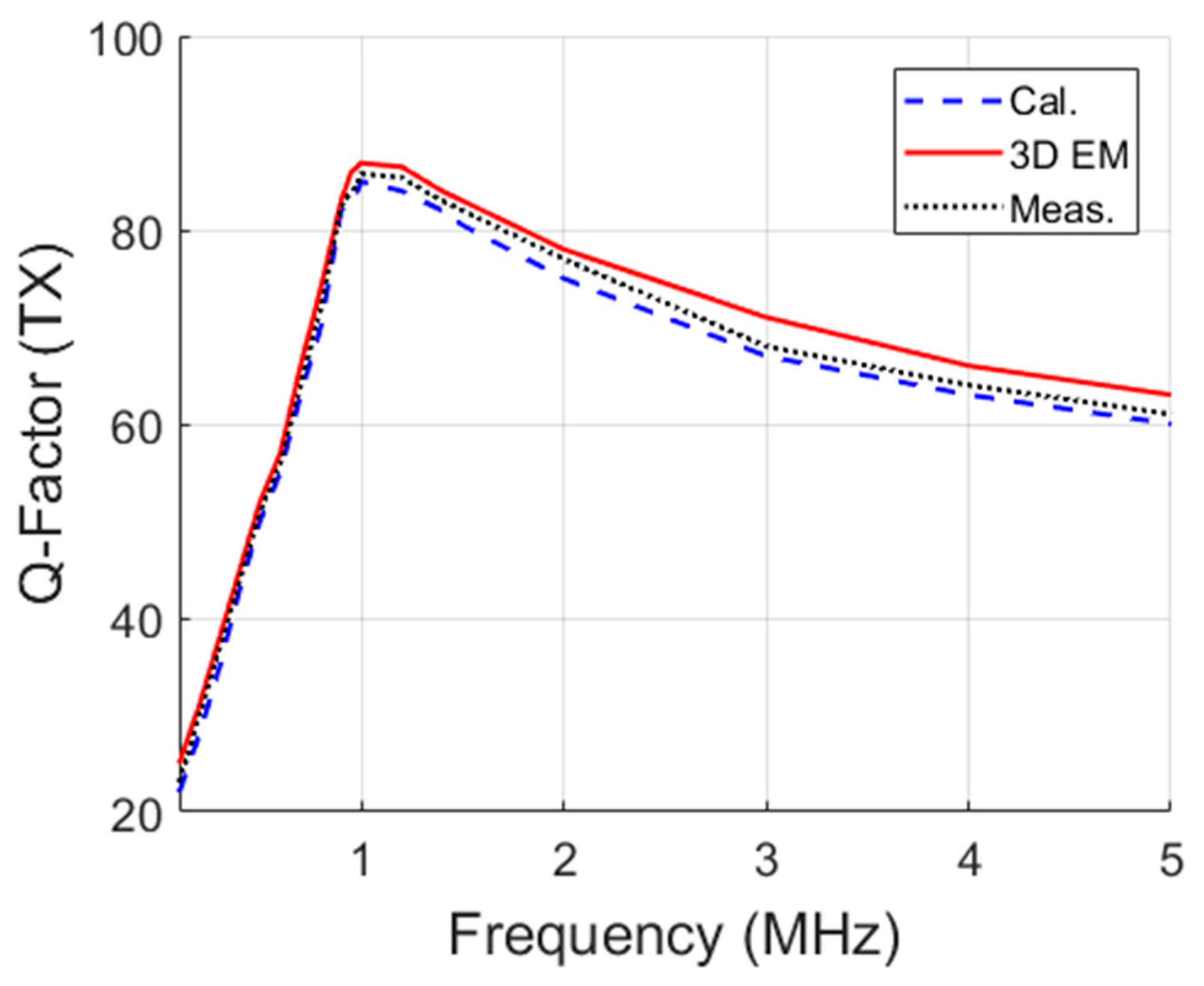
| TX | 101 | 2.5 | 2 | 14 | 30 | 88 |
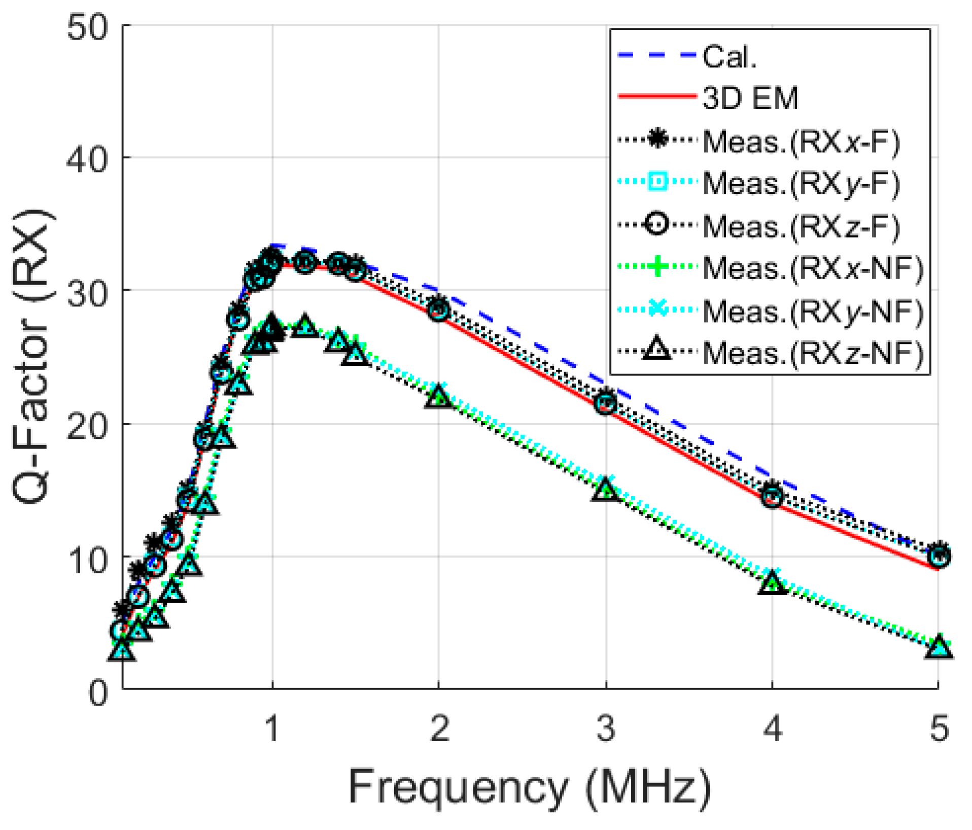
| RX (x-, y- and z-axis) | 4.45 | 0.2 | - | 35 | 8.3 | 33.5 |
| Parameter | [20] | [38] | [39] | [37] | This Work |
|---|---|---|---|---|---|
| TX Diameter (mm) | 400 | 220 | 23.5 | 200 | 200 |
| RX size (mm2) | 11.5 × 11.5 | 9 × 6 | 15 × 7 | 8 × 8 | 8.9 × 4.8 |
| Axes (D) | 3 | 1 | 1 | 3 | 3 |
| Distance (cm) | 20 | 7 | 5 | 10 | 10 |
| WL-PTE (%) | 5.02 | 0.7 | 1.21 | 1.3 | 1 |
| f (MHz) | 0.218 | 16.47 | 433.9 | 5 | 1 |
| SAR (W/kg) | 8 | 1.74 | 2.54 | 0.86 | 0.66 |
| Test environment | Air | Pig muscle | Duck intestine | Muscle phantom | Muscle phantom |
| FOM (×10−3) (25) | 4.08 | 0.0824 | 0.009 | 8.23 | 80 |
© 2019 by the authors. Licensee MDPI, Basel, Switzerland. This article is an open access article distributed under the terms and conditions of the Creative Commons Attribution (CC BY) license (http://creativecommons.org/licenses/by/4.0/).
Share and Cite
Khan, S.R.; Desmulliez, M.P.Y. Towards a Miniaturized 3D Receiver WPT System for Capsule Endoscopy. Micromachines 2019, 10, 545. https://doi.org/10.3390/mi10080545
Khan SR, Desmulliez MPY. Towards a Miniaturized 3D Receiver WPT System for Capsule Endoscopy. Micromachines. 2019; 10(8):545. https://doi.org/10.3390/mi10080545
Chicago/Turabian StyleKhan, Sadeque Reza, and Marc P.Y. Desmulliez. 2019. "Towards a Miniaturized 3D Receiver WPT System for Capsule Endoscopy" Micromachines 10, no. 8: 545. https://doi.org/10.3390/mi10080545
APA StyleKhan, S. R., & Desmulliez, M. P. Y. (2019). Towards a Miniaturized 3D Receiver WPT System for Capsule Endoscopy. Micromachines, 10(8), 545. https://doi.org/10.3390/mi10080545