Article

Concentric Split Aluminum with Silicon-Aluminum Nitride Annular Rings Resonators

School of Electronic Science and Engineering, University of Electronic Science and Technology of China, Chengdu 611731, China
*
Authors to whom correspondence should be addressed.
Micromachines 2019, 10(5), 296; https://doi.org/10.3390/mi10050296
Submission received: 31 March 2019 / Revised: 25 April 2019 / Accepted: 26 April 2019 / Published: 30 April 2019
(This article belongs to the Special Issue Advanced MEMS/NEMS Technology, Volume II)

Abstract

:
This paper presents a novel approach of annular concentric split rings microelectromechanical resonators with tether configuration to reduce anchor loss and gives very high-quality factor (Q) 2.97 Million based on FEA (Finite Element Analysis) simulation. The operating frequencies of these resonators are 188.55 MHz to 188.62 MHz. When the proposed SR (square rectangle) hole shaped one dimensional phononic crystal (1D PnC), and two dimensional phononic crystal (2D PnC) structure consist of very wide and complete band gaps is applied to novel design rings MEMS resonators, the quality factor (Q) further improved to 19.7 Million and 1750 Million, respectively, by using the finite element method. It is also observed that band gaps become closer by reducing the value of filling fraction, and proposed SR PnC gives extensive peak attenuation. Moreover, harmonic response of ring resonator is verified by the perfect match layers (PML) technique surrounded by resonators with varying width 1.5λ, and 3λ effectively reduce the vibration displacement.

1. Introduction

Nowadays, Micro-Electro-Mechanical-Systems (MEMS) components have been widely used in the field of engineering science, and technology because of their high efficiency, miniature in size, low power consumption, and low cost fabrication [1,2,3,4,5,6,7].
Several researchers [8,9,10,11,12,13,14,15,16] have demonstrated the ring resonators or (disc resonator with hole is developed in center). It is noted that operating frequency, and design of resonator play an important role in the performance and improving the quality factor of resonators. Moreover, the phononic crystal (PnC) having wide acoustic band gap is the key factor that can give the high-quality Q of microelectromechanical resonators.
To obtain the wide band gap, a lot of PnC structures have been designed [17,18,19,20,21,22,23,24,25], and applied to resonators of different shapes [18,19,20,22]. Phononic crystal can reduce the energy dissipated through anchors. Quality Q of the MEMS resonators has improved with phononic crystals extended to two dimension (2D). Many researcher employed phononic crystals with resonators’ body to improved quality of resonators, such as square shaped lattice PnC with hole employ with a resonator [26] gives quality 90,000, optimally shaped MEMS resonator [27] gives the quality 105,000, Cross shaped PnC MEMS resonator [23] gives 221,536, and gallium arsenide resonator [28] gives the quality of 6 million.
This work describes a design of novel SR (Square-Rectangle) hole shaped Phononic crystal, and this phononic crystal applied to novel annular concentric rings shaped Aluminium Nitride piezoelectric MEMS resonator.
At first, we have designed and simulated the unique silicon phononic crystal (PnC) structure of width 10 µm. we have also observed that reducing the value of filling fraction closer the band gaps. At second we have observed the band gaps generated by the 1D phononic crystal, and Eigen mode shapes of first 12 frequency bands. At third, we have observed the band gaps generated by the 2D phononic crystal, and Eigen mode shapes of first 12 frequency bands. At fourth, we have calculated transmission spectra through PnC for analyzing the band gaps, and leakage of energy. At fifth, we have designed and simulated the novel annular splits rings resonators with supporting tethers of width 4 µm to find the quality factor and investigated the displacement pattern and axes displacement of resonator, we have applied one dimensional phononic crystal (1D PnC) strips, and two dimensional phononic crystal (2D PnC) strips to annular splits rings resonators for further reduction of energy leakage and enhancement of the quality Q of resonator. In the end, we have investigated (x, y, z) displacement of resonator through FEA (Finite Element Analysis) simulation.

2. Phononic Crystals Structure and Band Gaps

During the last few years, Phononic crystal (PnC) is being under discussion of researchers due to its potential application in the field of technologies [15,24,25,29,30,31]. As the phononic crystals (PnCs) play an important role in development of micro/nanoelectronics, but it can also be involved in the improvement of quality of MEMS resonators. Many researchers employed phononic crystals to reduced anchor loss and improve the quality of resonators [19,26,32,33]. Dep et al. [34] also concluded that PnC based MEMS resonators can give the high quality. To reduce the anchor loss, one dimensional PnC strips were employed as an anchor of resonators [19]. Feng et al. [19] concluded that PnC strips can reduce the energy dissipated through anchors, and quality of ring resonators can be increased by increasing the number of phononic strips.
Phononic crystals can prevent energy leakage from resonators and control the elastic wave (acoustic wave) propagation inside the band [35,36]. It means that Phononic crystal does not allow elastic wave (acoustic wave) propagation in their structure due to the presence of band gaps. For the first time the propagation of elastic waves in phononic crystals is govern by one dimensional Bloch waves [37]. Actually, in any materials, there is band structure, and this structure is understandable by band gaps. At certain frequencies, the propagation of wave occurs, which are called bands, but at some frequencies range the propagation of wave stopped (cause of mechanical waves inside the PnC) are called band gaps. Phononic crystal can be one dimensional(1D) [19,38,39], two dimensional (2D) [35,40], and three dimensional(3D) [41,42]. To deduct the wider bandgap different shapes of phononic crystals were designed such as cylindrical pillars [43], honey comb [44], holes [30], square plates [39], etc.

3. Analysis of Phononic Band Gaps

The band gap in Phononic crystal (PnC) depends upon the properties of materials from which PnC made, density, and speed of sound in materials. Simply, we can say that band gap’s position with respect to frequency is the ratio of sound velocity to the size of periodic unit cell, and filling factor [45,46]. We have investigated the wave propagation in a novel air SR (Square-Rectangle) shaped phononic crystal unit cell consist of Si (silicon, anisotropic) through FE parametric solver which can sweep wave vector k. The air SR shape means the holey square and holey rectangles in PnC unit cell. The geometrical dimension of unit cell is 18.6 µm × 18.6 µm with centered horizontal and centred vertical air rectangles 18 µm × 4 µm (rectangles hole) and centered air square of 9.2 µm (square hole) each side, as shown in Figure 1b. The dimensions of centered rectangles hole and centered square hole, as shown in Figure 1b. The 3D view of PnC structure as shown in Figure 1c.
We analyzed the above periodic unit cell to evaluate the frequency response for 1D phononic crystal. The k parametric sweep fluctuates from 0 to 1. Where (0–1) indicate wave number of irreducible Brillouin zone (Γ–Χ). More generally, k swept from Γ to Χ (0 to π/a).
Moreover, the dispersion occurs when different wavelengths’ waves have different velocities of propagation. The dispersion relation associated with wave vector k to its frequency as follows
k = ω c
where ‘’ and ‘c’ are the angular frequency and wave velocity respectively.
Particularly for phononic crystal the dispersion relation is complex and is represent by frequency band curves schematic as shown in Figure 2.
Figure 2a obtained from FEA (Finite Element Analysis) simulation, red region shows that there is no wave propagation or no resonant mode in structure which covers a wide and complete bandgap. The band gaps generated by the 1D phononic crystal in Brillouin zone (Γ–Χ) is depicted in Figure 2a.
It is worth mention that bandgap also depend upon the geometrical dimension, and inclusion filling factor in PnC by using the following relation
( f α ) S i = area   of   inclusion   area   of   unit   cell
Air is used as high acoustic impedance material, and Aluminum Nitride (AIN) is low acoustic impedance material. The filling fraction of this SR (square rectangles) hole PnC is 0.542.
If the horizontal and vertical air rectangle is taken as 17 µm × 5 µm in size, and centered air square of 9 µm of each side, the band gap has reduced. We have observed that reducing the value of filling fraction closer the band gaps. The band gaps created into higher order modes due to smaller air inclusion area. The filling fractions and the band gap of phononic crystal obtained from different geometrical dimension, as shown in Table 1
We have also analyzed the above periodic unit cell to evaluate the frequency response for 2D phononic crystal. In 2D PnC structure the k parametric sweep fluctuates from 0 to 3. Where (0–1), (1–2), and (2–3) indicate wave number of irreducible Brillouin zone (Γ–Χ), (Χ–Μ), and (Μ–Γ) respectively. More generally k swept from Γ to Χ (0 to π/a), Χ to Μ (0 to π/a), and then Μ to Γ (π/a to 0).
Figure 3 obtained from FEA (Finite Element Analysis)) simulation, blue region shows that there is no wave propagation or no resonant mode in structure, which covers a wide and complete bandgap.
The red shaded, green shaded, and purple shaded area represents the deaf acoustic mode or deaf bandgap [47,48], because only resonant modes are allow to propagate in these range of frequencies. Deaf bands are the uncoupled band in dispersion relation. The frequency band structure of 3D plate model and eigenmode shapes of frequency bands with ka/2π = 0.25 is shown in Figure 3.
As this PnC structure employed to resonator for further reduction of energy leakage, so we have calculated transmission spectra through PnC for analyzing the leakage of energy, because transmission of acoustic waves is forbidden in a bandgap. The transmission is defined as the ratio of transmitted waves to incident waves, and calculated as the difference of probe displacement and source displacement.
T = 10 log (   d probe   2 d source 2 )
As the phononic crystal is employed to resonator with supporting tether length 12 µm, and width 4 µm on both sides of resonator. The motion of resonator is in y-direction and movement of Poisson coupling in x-, and z-directions. The x, y, and z excitations, as shown in Figure 4.
We have calculated the transmission wave spectra through finite thickness of 10 µm Phononic crystals as shown in Figure 4. Here we see that the attenuation peak is wider for x and y excitation as well as for z excitation, and no dip in transmission as compared in band diagram of Figure 5. A very minor transmission dip is observed only at 120 MHz in z excitation. Form Figure 5 we see that the band gap, wide peak attenuation, and operational frequency of resonator lie in the same frequency region. Thus, wider peak of attenuation makes a broader choice of desire operational frequencies of resonators. Thus, it is clear from Figure 5 that the transmission is very low and acoustic wave is banned in the yellow highlighted area (band gaps area).

4. Device Analysis

Annular concentric rings shaped Aluminum Nitride piezoelectric MEMS resonator is designed in this work, as shown in Figure 6.
The resonator is described with width of tether (Tw = 4 µm) without phononic crystal (PnC), and also with one dimensional phononic crystal (1D PnC), and two dimensional phononic crystal (2D PnC).
The equation of frequency for annular ring, disks [8,9,45,46,47,49,50] and mode shape [51] with general elastic boundary conditions is given in the following way.
[ J 1 ( ω R 0 c ) [ M 1 ( ω R 0 c ) ( 1 σ ) ] Y 1 ( ω R 0 c ) [ N 1 ( ω R 0 c ) ( 1 σ ) ] J 1 ( ω R i c ) [ M 1 ( ω R i c ) ( 1 σ ) ] Y 1 ( ω R i c ) [ N 1 ( ω R i c ) ( 1 σ ) ] ]
where (J, and Y) are the first, and second kind of Bessel functions, and (M, and N) are modified form of Bessel functions, R0, and Ri are the outer and inner radius.
The Aluminum Nitride (AlN) as piezoelectric material is taken in ring shaped resonator, so the resonant frequency [9,52] can be governed in the following way
f = 1 λ E p ρ ( 1 σ 2 )
where λ = 2W, Ep, ρ, and σ are width of resonator mode (wavelength), Young’s Modulus, Poisson’s ratio, and effective mass density of piezoelectric material, respectively. We have set the primary alignment of resonators structure to <110> frame of reference for silicon elasticity matrix [53] in (COMSOL Multiphysics 5.4) as below
[   194.5 35.7 64.1 0 0 0 35.7 194.5 64.1 0 0 0 64.1 64.1 165.7 0 0 0 0 0 0 79.6 0 0 0 0 0 0 79.6 0 0 0 0 0 0 50.9 ] Gpa
Some other important parameters of medium/materials used in this work are listed in Table 2.
When the potential is applied between aluminum electrodes, the electric field is developed the induced mechanical strain along aluminum nitride piezoelectric material, this is due to inverse effect of piezoelectric, as a result mode of vibration appears. The mode shape vibration of resonator is depicted in Figure 7 and Figure 8. Both Figures indicate the good pattern of mode shapes based upon the analysis of corresponding eigen frequencies through FEA simulation.
In this study we have also obtained high Q by employing PnCs to resonators through FEA (Finite Element Analysis) simulation. There are few energy loss mechanisms comprise the total Q-factor of the device [54]. Their losses are given as Support (anchor) loss, Viscous damping, Electrical damping, Loss due to structural asymmetry, and Thermo-Elastic Damping (TED).
1 Q total = 1 Q anchor + 1 Q viscous   damping + 1 Q electrical   damping + 1 Q material + 1 Q TED
In this study only anchor loss is considered (through FEA simulation), and the other losses are completely omitted. Due to nature of motion resonator it is not affected by air damping, and the material losses are difficult to predict, so the major loss is anchor loss [33,55,56]. The energy loss mechanism in MEM resonator is also demonstrated by Akhieser effect (AKE) [57]. Moreover Frangi et al. [58,59] reported that all thermoelastic losses (Akhieser losses) are included due to sources of dissipation. These Akhieser losses are generally negligible because piezoelectric MEM resonators operate in one of its bulk modes, and only the anchor loss deserve attention.
We have analyzed the Quality Q of proposed resonator without PnC, employed with 1D PnC, and with 2D PnC by the following summarized relation [60,61].
Q = 2 π E s E l
where Es and El are the energy stored (vibration energy) and energy loss (energy dissipation per cycle of vibration) in resonator.
Figure 9 show that the tether (width 4 µm) is attached with 2D PnC, and resonator is bounded with PML (perfect match layer). The width of PML is set as varying ‘aλ’ (a = 1.5 and 3, and λ = 45 µm) (Table 3). Elastic waves are produced by resonator through tether, this is the major loss of energy. Specific dimension of PML can prevent resonator from reflecting elastic waves, because the elastic waves can be absorbed by PML [57,62,63]. Thus, we have used the perfect match layer through FEA (Finite Element Analysis) simulation to reduce the energy leakage through tethers. Reducing the energy leakage means increasing the quality factor. So Qanchor is obtained by resonant frequency f0 over band width −3 dB [33,56,58]
Q anchor = f 0 3   dB ( Δ f ) = R e ( ω ) 2 I m ( ω )
where ‘ꞷ’ is the desired mode’s eigen frequency of the resonator in FEA simulation.
The response of annular rings resonators is obtained by suppling the voltage source of 1 V to electrodes. Figure 10 and Figure 11 show the displacement of resonators along x, y, and z directions without, and with pnC structure through frequency domain FEA simulations.
These results declare that resonators with perfect match layer (PML) width approximately equal to 3λ ≈ 135 µm reduced the displacement of vibration, as shown in Figure 11. The Perfect match layer (artificial absorbing layers) technique is firstly described by Pierre [64]. Moreover, wide PML curtail the frequency domain and acts as an isotropic absorber or simply we can say it acts like an artificial boundary.
Figure 12 differentiate the Quality (obtained from FEA simulations) between resonators without PnC structure, with 1D PnC structure, with 2D PnC (with perfect match layer (PML) width = 1.5λ, 3λ, respectively). These results show that Quality Q of resonator is the highest when 2D Phononic crystal structure is employed to resonators.
We see that, this unique design of resonators gives high quality, and when PnC is employed to resonator, the energy isolate from the resonator to substrate (reducing the loss of energy) as a result Q further increased. Furthermore, band gap of designed PnC covers the operating frequency of designed resonators, and the design of this SR PnC will help to increase the quality of further designing of resonators in future.

5. Conclusions

In this work, we have presented a new approach of annular concentric split rings microelectromechanical resonators with tether configuration to reduce anchor loss and gives very high-quality factor (Q) 2.9 Million. These resonators were operating between the frequency 188.55 MHz and 188.62 MHz. In this works we have also proposed SR (square rectangle) hole shaped phononic crystal structure, which gives very wide and complete band gaps. When SR (square rectangle) shaped one dimensional phononic crystal (1D PnC), and two dimensional phononic crystal (2D PnC) is employed to novel design rings MEMS resonators the quality factor (Q) further improved to 19.7 Million and 1750 Million, respectively. We have concluded that value of filling fraction is reduced then band gaps become closer. It is observed that wider peak of attenuation makes broader desired operational frequencies of resonators.
We have also verified the harmonic response of annular rings resonators by perfect match layers (PML) technique surrounded to resonators with varying width 1.5λ, and 3λ effectively reduce the vibration displacement.

Author Contributions

Conceptualization, M.A.K. and J.-F.B.; Methodology, M.A.K.; Software, M.A.K., F.-H.B., and X.Z.; Validation, M.A.K., F.-H.B., and X.Z.; Formal Analysis, M.A.K. and J.-F.B. Investigation, M.A.K., F.-H.B., and X.Z.; Resources, M.A.K., F.-H.B., and X.Z.; Data Curation, M.A.K., F.-H.B., and X.Z.; Writing-Original Draft Preparation, M.A.K.; Writing-Review & Editing, M.A.K., F.-H.B.; Visualization, M.A.K.; Supervision, J.-F.B.; Project Administration, J.-F.B.; Funding Acquisition, M.A.K., J.-F.B.

Funding

This work is supported by National Natural Science Foundation of China, and China Academy of Engineering Physics under Grant No. U1430102.

Acknowledgments

We are thankful to Lubna Razia from School of Biomedical Engineering, University of Electronic Science and Technology of China for the fruitful discussions about phononic crystals.

Conflicts of Interest

The authors declare no conflict of interest.

References

  1. Wang, H.; Lenz, H.; Szabo, A.; Bamberger, J.; Hanebeck, U.D. WLAN-Based Pedestrian Tracking Using Particle Filters and Low-Cost MEMS Sensors. In Proceedings of the 2007 4th Workshop on Positioning, Navigation and Communication, Hannover, Germany, 22 March 2007; pp. 1–7. [Google Scholar]
  2. Shin, S.H.; Park, C.G.; Kim, J.W.; Hong, H.S.; Lee, J.M. Adaptive Step Length Estimation Algorithm Using Low-Cost MEMS Inertial Sensors. In Proceedings of the 2007 IEEE Sensors Applications Symposium, San Diego, CA, USA, 6–8 February 2007; pp. 1–5. [Google Scholar]
  3. Cohen, A.; Zhang, G.; Tseng, F.-G.; Frodis, U.; Mansfeld, F.; Will, P. EFAB: Rapid, low-cost desktop micromachining of high aspect ratio true 3-D MEMS. In Proceedings of the Twelfth IEEE International Conference on Micro Electro Mechanical Systems (Cat. No.99CH36291), Orlando, FL, USA, 21 January 1999; pp. 244–251. [Google Scholar]
  4. Obuh, I.E.; Doychinov, V.; Steenson, D.P.; Akkaraekthalin, P.; Robertson, I.D.; Somjit, N. Low-Cost Microfabrication for MEMS Switches and Varactors. IEEE Trans. Components Packag. Manuf. Technol. 2018, 8, 1702–1710. [Google Scholar] [CrossRef] [Green Version]
  5. Breen, M.; Streyer, W.; Lu, R.; Gao, A.; Wasserman, D.; Gong, S. High speed mid-infrared detectors based on MEMS resonators and spectrally selective metamaterials. In Proceedings of the 2016 IEEE International Frequency Control Symposium (IFCS), New Orleans, LA, USA, 9–12 May 2016; pp. 1–6. [Google Scholar]
  6. Partridge, A.; Tabatabaei, S. Silicon MEMS oscillators for high speed digital systems. In Proceedings of the 2009 IEEE Hot Chips 21 Symposium (HCS), Stanford, CA, USA, 23–25 August 2009; pp. 1–25. [Google Scholar]
  7. Banerji, S.; Fernandez, D.; Madrenas, J. A Comprehensive High-Level Model for CMOS-MEMS Resonators. IEEE Sens. J. 2018, 18, 2632–2640. [Google Scholar] [CrossRef]
  8. Ambati, G.; Bell, J.F.W.; Sharp, J.C.K. In-plane vibrations of annular rings. J. Sound Vib. 1976, 47, 415–432. [Google Scholar] [CrossRef] [Green Version]
  9. Piazza, G.; Stephanou, P.J.; Pisano, A.P. Piezoelectric Aluminum Nitride Vibrating Contour-Mode MEMS Resonators. J. Microelectromech. Syst. 2006, 15, 1406–1418. [Google Scholar] [CrossRef] [Green Version]
  10. Zolfaghari, P.; Zadehsafari, M.; Akbari, A.; Ghavifekr, H.B. An acoustic piezoelectric ring-shape Lamb wave MEMS resonator. In Proceedings of the 2017 4th International Conference on Electrical and Electronic Engineering (ICEEE), Ankara, Turkey, 8–10 April 2017; pp. 23–27. [Google Scholar]
  11. Kasambe, P.V.; Asgaonkar, V.V.; Bangera, A.D.; Lokre, A.S.; Rathod, S.S.; Bhoir, D.V. Piezoelectric Lead Zirconate Titanate (PZT) Ring Shaped Contour-Mode MEMS Resonators. IOP Conf. Ser. Mater. Sci. Eng. 2018, 310, 012069. [Google Scholar] [CrossRef]
  12. Bijari, A.; Keshmiri, S.-H.; Babazadeh, F.; Bijari, A.; Keshmiri, S.-H.; Babazadeh, F. Nonlinear Modeling for Distortion Analysis in Silicon Bulk-Mode Ring Resonators. Micromachines 2012, 3, 582–603. [Google Scholar] [CrossRef] [Green Version]
  13. Yan, S.; Li, M.; Luo, L.; Ma, K.; Xue, C.; Zhang, W. Optimisation Design of Coupling Region Based on SOI Micro-Ring Resonator. Micromachines 2014, 6, 151–159. [Google Scholar] [CrossRef] [Green Version]
  14. Yen, M.H.; Feng, P.Y.; Lin, C.E.; Chen, C.C.; Chang, J.Y. Optimization of Pulley-Type Ring Resonator with Waveguide Offset. Micromachines 2018, 9, 226. [Google Scholar] [CrossRef]
  15. Zhou, X.; Xiao, D.; Li, Q.; Hu, Q.; Hou, Z.; He, K.; Chen, Z.; Zhao, C.; Wu, Y.; Seshia, A. Investigation on the Quality Factor Limit of the (111) Silicon Based Disk Resonator. Micromachines 2018, 9, 25. [Google Scholar] [CrossRef] [PubMed]
  16. Piazza, G.; Stephanou, P.J.; Pisano, A.P. Single-Chip Multiple-Frequency ALN MEMS Filters Based on Contour-Mode Piezoelectric Resonators. J. Microelectromech. Syst. 2007, 16, 319–328. [Google Scholar] [CrossRef] [Green Version]
  17. Siddiqi, M.W.U.; Lee, J.E.Y. AlN-on-Si MEMS resonator bounded by wide acoustic bandgap two-dimensional phononic crystal anchors. In Proceedings of the 2018 IEEE Micro Electro Mechanical Systems (MEMS), Belfast, UK, 21–25 January 2018; pp. 727–730. [Google Scholar]
  18. Siddiqi, M.W.U.; Lee, J.E.Y. Wide acoustic bandgap solid disk-shaped phononic crystal anchoring boundaries for enhancing quality factor in AlN-on-Si MEMS resonators. Micromachines 2018, 9, 413. [Google Scholar] [CrossRef]
  19. Feng, D.; Xu, D.; Wu, G.; Xiong, B.; Wang, Y. Phononic crystal strip based anchors for reducing anchor loss of micromechanical resonators. J. Appl. Phys. 2014, 115, 024503. [Google Scholar] [CrossRef]
  20. Wu, G.; Zhu, Y.; Merugu, S.; Wang, N.; Sun, C.; Gu, Y. GHz spurious mode free AlN lamb wave resonator with high figure of merit using one dimensional phononic crystal tethers. Appl. Phys. Lett. 2016, 109, 013506. [Google Scholar] [CrossRef]
  21. Rawat, U.; Nair, D.R.; Dasgupta, A. Piezoelectric-on-Silicon Array Resonators with Asymmetric Phononic Crystal Tethering. J. Microelectromech. Syst. 2017, 26, 773–781. [Google Scholar] [CrossRef]
  22. Ha, T.D.; Bao, J.F. Reducing anchor loss in thin-film aluminum nitride-on-diamond contour mode MEMS resonators with support tethers based on phononic crystal strip and reflector. Microsyst. Technol. 2016, 22, 791–800. [Google Scholar] [CrossRef]
  23. Awad, M.; Bao, F.; Bao, J.; Zhang, X. Cross-shaped PnC for anchor loss reduction of thin-film ALN-on-silicon high frequency MEMS resonator. In Proceedings of the 2018 IEEE MTT-S International Wireless Symposium (IWS), Chengdu, China, 6–10 May 2018; pp. 1–3. [Google Scholar]
  24. Miranda, E.J.P.; Santos, J.M.C.D. Evanescent Bloch waves and complex band structure in magnetoelectroelastic phononic crystals. Mech. Syst. Signal Process. 2018, 112, 280–304. [Google Scholar] [CrossRef]
  25. Manktelow, K.; Narisetti, R.K.; Leamy, M.J.; Ruzzene, M. Finite-element based perturbation analysis of wave propagation in nonlinear periodic structures. Mech. Syst. Signal Process. 2013, 39, 32–46. [Google Scholar] [CrossRef]
  26. Zhu, H.; Lee, J.E.-Y. AlN piezoelectric on silicon MEMS resonator with boosted Q using planar patterned phononic crystals on anchors. In Proceedings of the 2015 28th IEEE International Conference on Micro Electro Mechanical Systems (MEMS), Estoril, Portugal, 18–22 January 2015; pp. 797–800. [Google Scholar]
  27. Ardito, R.; Cremonesi, M.; D’Alessandro, L.; Frangi, A. Application of optimally-shaped phononic crystals to reduce anchor losses of MEMS resonators. In Proceedings of the 2016 IEEE International Ultrasonics Symposium (IUS), Tours, France, 18–21 September 2016; pp. 1–3. [Google Scholar]
  28. Guha, B.; Marsault, F.; Cadiz, F.; Morgenroth, L.; Ulin, V.; Berkovitz, V.; Lemaître, A.; Gomez, C.; Amo, A.; Combrié, S.; et al. Surface-enhanced gallium arsenide photonic resonator with quality factor of 6 × 10⁶. Optica 2017, 4, 218. [Google Scholar] [CrossRef]
  29. Yablonovitch, E. Inhibited Spontaneous Emission in Solid-State Physics and Electronics. Phys. Rev. Lett. 1987, 58, 2059–2062. [Google Scholar] [CrossRef] [PubMed]
  30. Assouar, M.B.; Sun, J.-H.; Lin, F.-S.; Hsu, J.-C. Hybrid phononic crystal plates for lowering and widening acoustic band gaps. Ultrasonics 2014, 54, 2159–2164. [Google Scholar] [CrossRef]
  31. Jing-Fu, B.; Khan, M.A.; Fei-Hong, B. Phononic Crystal Resonators. In Phonons in Low Dimensional Structures; IntechOpen: London, UK, 2018. [Google Scholar]
  32. Hsu, F.-C.; Hsu, J.-C.; Huang, T.-C.; Wang, C.-H.; Chang, P. Design of lossless anchors for microacoustic-wave resonators utilizing phononic crystal strips. Appl. Phys. Lett. 2011, 98, 143505. [Google Scholar] [CrossRef]
  33. Lin, C.-M.; Hsu, J.-C.; Senesky, D.G.; Pisano, A.P. Anchor loss reduction in ALN Lamb wave resonators using phononic crystal strip tethers. In Proceedings of the 2014 IEEE International Frequency Control Symposium (FCS), Taipei, Taiwan, 12–22 May 2014; pp. 1–5. [Google Scholar]
  34. Ha, T.D.; Bao, J. A phononic crystal strip based on silicon for support tether applications in silicon-based MEMS resonators and effects of temperature and dopant on its band gap characteristics. AIP Adv. 2016, 6, 045211. [Google Scholar] [CrossRef] [Green Version]
  35. Nassar, H.; Chen, H.; Norris, A.N.; Huang, G.L. Quantization of band tilting in modulated phononic crystals. Phys. Rev. B 2018, 97, 014305. [Google Scholar] [CrossRef]
  36. Wang, S.; Popa, L.C.; Weinstein, D. GaN MEMS resonator using a folded phononic crystal structure. Proc. Solid-State Sens., Actuators, Microsyst. Workshop 2014, 1, 72–75. [Google Scholar]
  37. Ren, S.Y. Complete quantum confinement of one-dimensional Bloch waves. Phys. Rev. B 2001, 64, 035322. [Google Scholar] [CrossRef]
  38. Sause, M.G.R.; Hamstad, M.A. Numerical modeling of existing acoustic emission sensor absolute calibration approaches. Sens. Actuators A Phys. 2018, 269, 294–307. [Google Scholar] [CrossRef]
  39. Zou, K.; Ma, T.-X.; Wang, Y.-S. Investigation of complete bandgaps in a piezoelectric slab covered with periodically structured coatings. Ultrasonics 2016, 65, 268–276. [Google Scholar] [CrossRef]
  40. Rottenberg, X.; Jansen, R.; Tilmans, H.A.C. Phononic BandGap coupled Bulk Acoustic wave Resonators. In Proceedings of the 2012 IEEE 25th International Conference on Micro Electro Mechanical Systems (MEMS), Paris, France, 29 Janaury–2 February 2012; pp. 725–728. [Google Scholar]
  41. Delpero, T.; Schoenwald, S.; Zemp, A.; Bergamini, A. Structural engineering of three-dimensional phononic crystals. J. Sound Vib. 2016, 363, 156–165. [Google Scholar] [CrossRef]
  42. Babaee, S.; Wang, P.; Bertoldi, K. Three-dimensional adaptive soft phononic crystals. J. Appl. Phys. 2015, 117, 244903. [Google Scholar] [CrossRef]
  43. Pourabolghasem, R.; Mohammadi, S.; Eftekhar, A.A.; Khelif, A.; Adibi, A. Experimental evidence of high-frequency complete elastic bandgap in pillar-based phononic slabs. Appl. Phys. Lett. 2014, 105, 231908. [Google Scholar] [CrossRef]
  44. Gao, Z.; Fang, J.; Zhang, Y.; Jiang, L. Band structure research of a 2D honeycomb lattice phononic crystal. Int. J. Electrochem. Sci. 2013, 8, 7918–7925. [Google Scholar]
  45. Gruszka, K.; Nabiałek, M.; Szota, M. The influence of fill factor on the phononic crystal eigenfrequencies. Arch. Mater. Sci. Eng. 2014, 66, 74–80. [Google Scholar]
  46. Oltulu, O.; Mamedov, A.M.; Ozbay, E. Band gap structure of elliptic rods in water for a 2D phononic crystal. Appl. Phys. A 2017, 123, 212. [Google Scholar] [CrossRef]
  47. Gorisse, M.; Benchabane, S.; Teissier, G.; Billard, C.; Reinhardt, A.; Laude, V.; Defaÿ, E.; Aïd, M. Observation of band gaps in the gigahertz range and deaf bands in a hypersonic aluminum nitride phononic crystal slab. Appl. Phys. Lett. 2011, 98, 234103. [Google Scholar] [CrossRef]
  48. Hsiao, F.-L.; Khelif, A.; Moubchir, H.; Choujaa, A.; Chen, C.-C.; Laude, V. Complete band gaps and deaf bands of triangular and honeycomb water-steel phononic crystals. J. Appl. Phys. 2007, 101, 044903. [Google Scholar] [CrossRef]
  49. Shi, X.; Shi, D.; Qin, Z.; Wang, Q. In-Plane Vibration Analysis of Annular Plates with Arbitrary Boundary Conditions. Sci. World J. 2014, 2014, 653836. [Google Scholar] [CrossRef] [PubMed]
  50. Bashmal, S.; Bhat, R.; Rakheja, S. In-plane free vibration of circular annular disks. J. Sound Vib. 2009, 322, 216–226. [Google Scholar] [CrossRef]
  51. Bashmal, S.; Bhat, R.; Rakheja, S. Frequency Equations for the In-Plane Vibration of Circular Annular Disks. Adv. Acoust. Vib. 2010, 2010, 501902. [Google Scholar] [CrossRef]
  52. Siddiqi, M.W.U.; Tu, C.; Lee, J.E.-Y. Effect of mode order, resonator length, curvature, and electrode coverage on enhancing the performance of biconvex resonators. J. Micromech. Microeng. 2018, 28, 094002. [Google Scholar] [CrossRef] [Green Version]
  53. Khine, L.; Palaniapan, M.; Shao, L.; Wong, W.K. Characterization of SOI Lamé-mode square resonators. In Proceedings of the 2008 IEEE International Frequency Control Symposium, Honolulu, HI, USA, 19–21 May 2008; pp. 625–628. [Google Scholar]
  54. Hopcroft, M.A.; Nix, W.D.; Kenny, T.W. What is the Young’s Modulus of Silicon? J. Microelectromech. Syst. 2010, 19, 229–238. [Google Scholar] [CrossRef]
  55. Braginsky, V.B.; Mitrofanov, V.P.; Panov, V.I.; Krotkov, R. Systems with Small Dissipation. Am. J. Phys. 1987, 55, 1153–1154. [Google Scholar] [CrossRef]
  56. Zou, J.; Lin, C.-M.; Tang, G.; Pisano, A.P. High-Q Butterfly-Shaped AlN Lamb Wave Resonators. IEEE Electron Device Lett. 2017, 38, 1739–1742. [Google Scholar] [CrossRef]
  57. Chen, Y.-Y.; Lai, Y.-T.; Lin, C.-M. Finite element analysis of anchor loss in AlN Lamb wave resonators. In Proceedings of the 2014 IEEE International Frequency Control Symposium (FCS), Taipei, Taiwan, 19–22 May 2014; pp. 1–5. [Google Scholar]
  58. Chandorkar, S.A.; Agarwal, M.; Melamud, R.; Candler, R.N.; Goodson, K.E.; Kenny, T.W. Limits of quality factor in bulk-mode micromechanical resonators. In Proceedings of the 2008 IEEE 21st International Conference on Micro Electro Mechanical Systems, Wuhan, China, 13–17 January 2008; pp. 74–77. [Google Scholar]
  59. Frangi, A.; Cremonesi, M.; Jaakkola, A.; Pensala, T. Analysis of anchor and interface losses in piezoelectric MEMS resonators. Sens. Actuators A Phys. 2013, 190, 127–135. [Google Scholar] [CrossRef]
  60. Frangi, A.; Cremonesi, M.; Jaakkola, A.; Bathe, K. Optimization of MEMS Piezo-Resonators. Struct. Longev. 2012, 7, 129–134. [Google Scholar]
  61. Zou, J.; Lin, C.-M.; Pisano, A.P. Quality factor enhancement in Lamb wave resonators utilizing butterfly-shaped AlN plates. In Proceedings of the 2014 IEEE International Ultrasonics Symposium, Chicago, IL, USA, 3–6 September 2014; pp. 81–84. [Google Scholar]
  62. Zou, J.; Lin, C.-M.; Pisano, A.P. Anchor loss suppression using butterfly-shaped plates for AlN Lamb wave resonators. In Proceedings of the 2015 Joint Conference of the IEEE International Frequency Control Symposium & the European Frequency and Time Forum, Denver, CO, USA, 12–16 April 2015; pp. 432–435. [Google Scholar]
  63. Bindel, D.S.; Govindjee, S. Elastic PMLs for resonator anchor loss simulation. Int. J. Numer. Methods Eng. 2005, 64, 789–818. [Google Scholar] [CrossRef]
  64. Berenger, J.-P. A perfectly matched layer for the absorption of electromagnetic waves. J. Comput. Phys. 1994, 114, 185–200. [Google Scholar] [CrossRef]
Figure 1. (a) Irreducible Brillouin Zone of phononic crystal. (b) Schematic of unit cell with lattice parameter a = 18.6 µm. (c) 3D view of PnC unit cell.
Micromachines 10 00296 g001
Figure 2. (a) Frequency band structure curves in irreducible Brillouin zone [(0–1) (Γ–Χ)] of 1D PnC investigated through FE method. (dotted lines indicate the dispersion curves of elastic waves) red area represent complete bandgaps. (b) Eigen mode shapes of the first 12 frequency bands.
Micromachines 10 00296 g002
Figure 3. (a) Frequency band structure curves in irreducible Brillouin zone [(Γ–Χ), (Χ–Μ), and (Μ–Γ)] of 2D PnC investigated through FE method. (dotted lines indicate the dispersion curves of elastic waves) blue area represent complete bandgaps. (b) Eigen mode shapes of first 12 frequency bands.
Micromachines 10 00296 g003
Figure 4. Transmission Vs Frequency for three different excitations investigated through the FE method.
Micromachines 10 00296 g004
Figure 5. Comparison between bandgap graph and transmission for 2D PnC with lattice a = 18.6 µm, f = 0.542.
Micromachines 10 00296 g005
Figure 6. Schematic of annular concentric rings shaped Aluminium Nitride piezoelectric resonator with tether width 4 µm.
Micromachines 10 00296 g006
Figure 7. FEA Simulations of Displacement field pattern in the resonators with perfect match layer (PML) width = 1.5λ: (a) (Without Pnc) Mode shape at frequency f = 188.55 MHz. (b) (With 1D Pnc) Mode shape at frequency f = 188.6 MHz. (c) (With 2D Pnc) Mode shape at frequency f = 188.6 MHz.
Micromachines 10 00296 g007
Figure 8. FEA Simulations of Displacement field pattern in the resonators with perfect match layer (PML) width = 3λ: (a) (Without Pnc) Mode shape at frequency f = 188.57 MHz. (b) (With 1D Pnc) Mode shape at frequency f = 188.62 MHz. (c) (With 2D Pnc) Mode shape at frequency f = 188.6 MHz.
Micromachines 10 00296 g008
Figure 9. Schematic view of concentric rings resonator using phonic crystals surrounded by perfect match layers (PML) (inset: closed view of tether attached with 2D PnC.
Micromachines 10 00296 g009
Figure 10. Investigation of (x,y,z) displacement of resonator: (a) without PnC structure.(b) 1D PnC structure. (c) 2D PnC with perfect match layer (PML) width = 1.5λ obtained from FEA simulations.
Micromachines 10 00296 g010
Figure 11. Investigation of (x,y,z) displacement of resonator: (a) Without PnC structure. (b) 1D PnC structure. (c) 2D PnC with perfect match layer (PML) width = 3λ obtained from FEA simulations.
Micromachines 10 00296 g011
Figure 12. Quality of resonators without PnC structure, with 1D PnC structure, with 2D PnC (with perfect match layer (PML) width = 1.5λ, 3λ) obtained from FEA simulations.
Micromachines 10 00296 g012
Table 1. Simulation parameters of PnC structures.
Rectangle Hole (µm2)Square Hole (µm2)Maximum Bandgap (MHz)(fα)si
18 × 49.2 × 9.275–1840.542
17 × 59 × 9103.8–195.50.511
16 × 68.8 × 8.8121–192.50.481
Table 2. Properties of Materials/Medium.
Medium/MaterialsParameters
Silicon (Si)Density (ρ) = 2330 kg/m3
Aluminum Nitride (AIN)Density (ρ) = 3300 kg/m3
Relative permittivity (ε) = 9
Poisson’s ratio (ν) = 0.24
Young’s Modulus (E) = 320 Gpa
Aluminum (Al)Density (ρ) = 2700 kg/m3
Young’s Modulus (E) = 70 Gpa
Poisson’s ratio (ν) = 0.35
Electrical conductivity (σ) = 35.5 × 10⁶ S/m
Coefficient of thermal expansion (α) = 23.1 × 10⁻⁶/K
Heat capacity (Cp) = 904 J/Kg K
Thermal conductivity (κ) = 237 W/mK
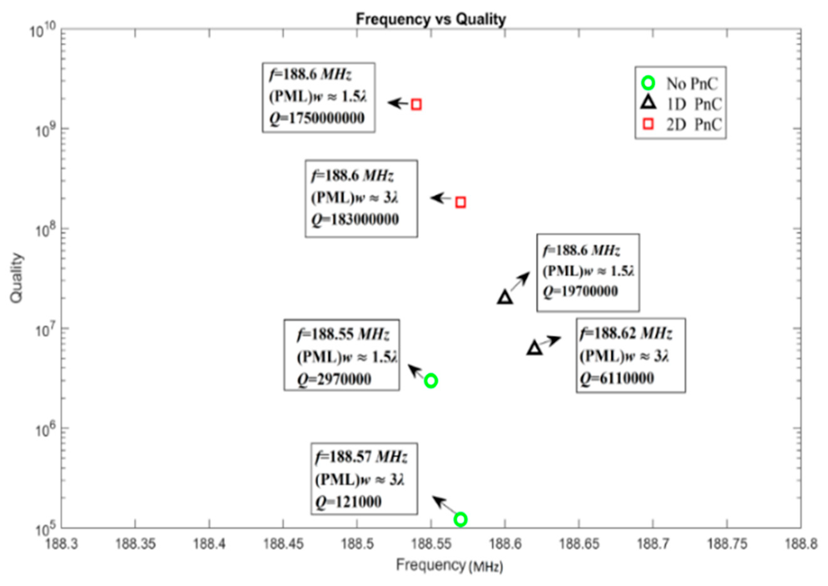
Table 3. Simulation parameters of PML width surrounded with resonators.
StructureFrequency (MHz)PML Width (λ ≈ 45 µm)Quality
Without PnC188.551.5λ2970,000
188.573λ121,000
With 1D PnC188.61.5λ19,700,000
188.623λ6,110,000
With 2D PnC188.61.5λ1,750,000,000
188.63λ183,000,000

