Study of Flow Characteristics of Gas Mixtures in a Rectangular Knudsen Pump


Abstract
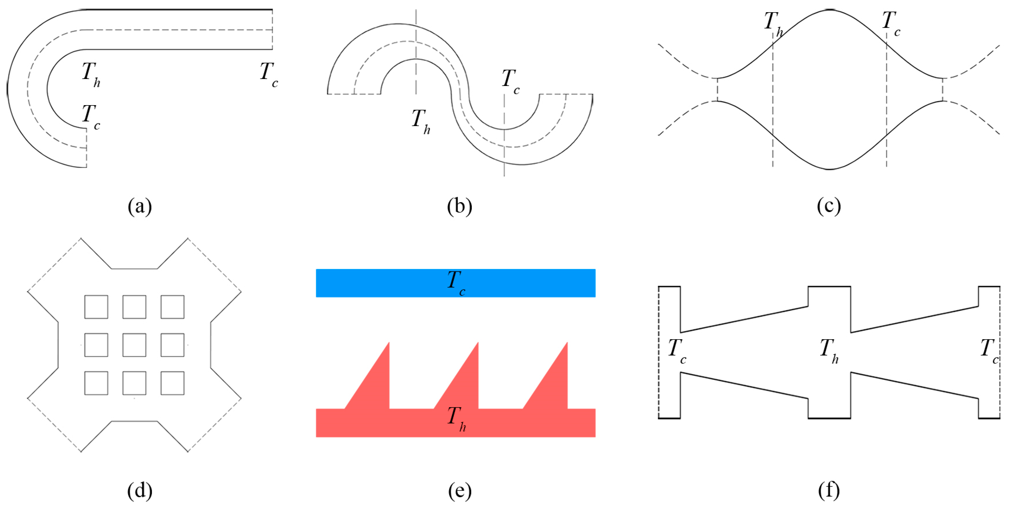
1. Introduction
2. Problem Statement and Numerical Method
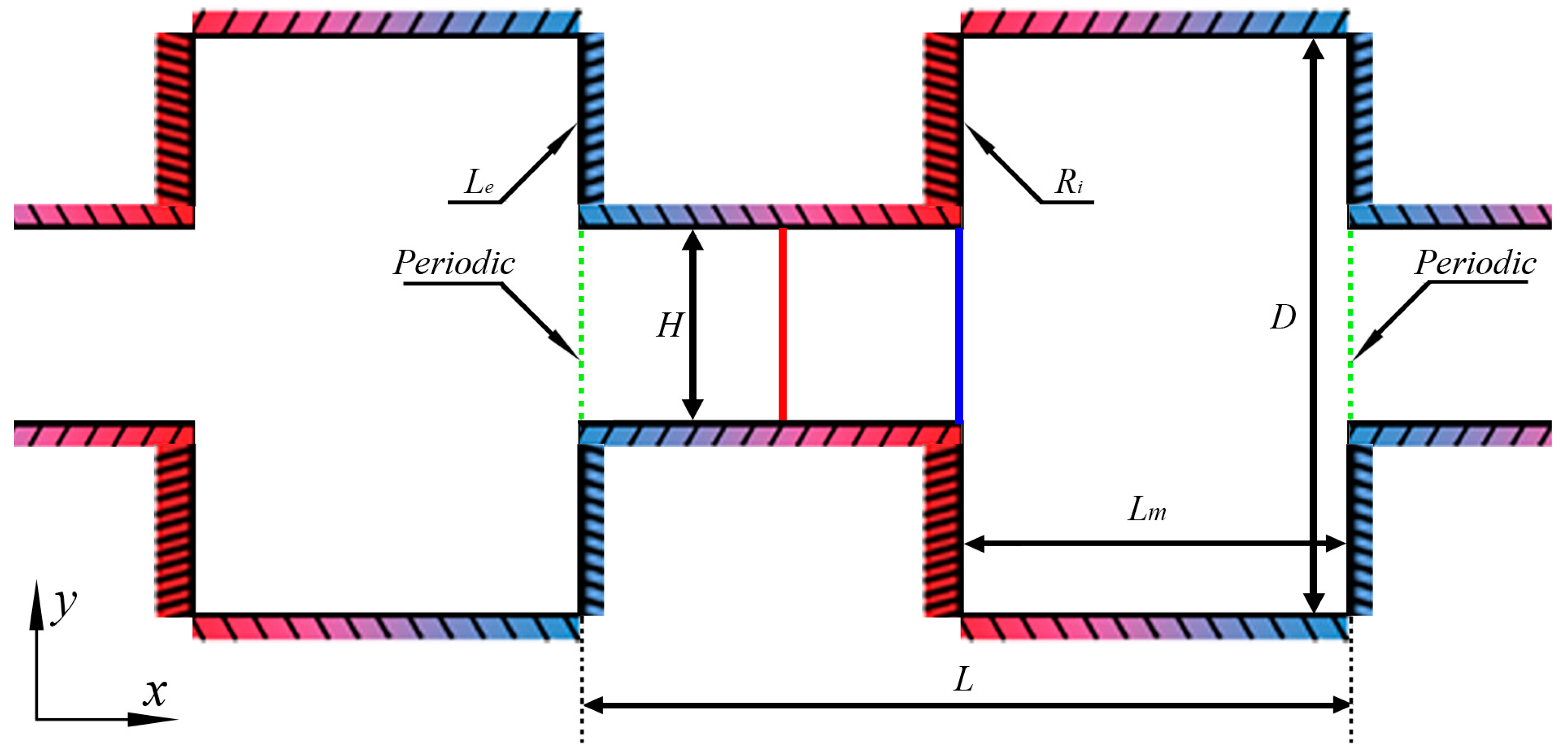
2.1. Problem Statement
2.2. DSMC Method
2.3. Code Validation
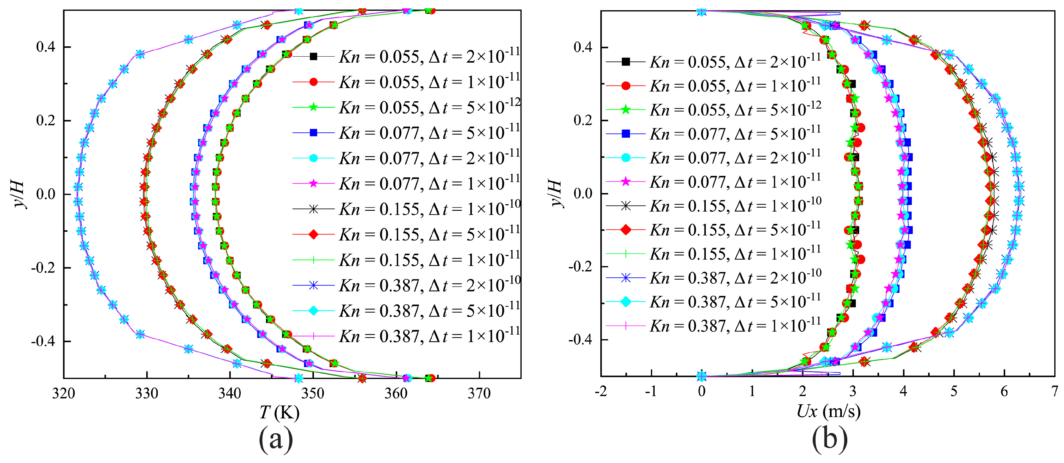
2.4. Grid, Particle and Time Step
3. Results and Discussion
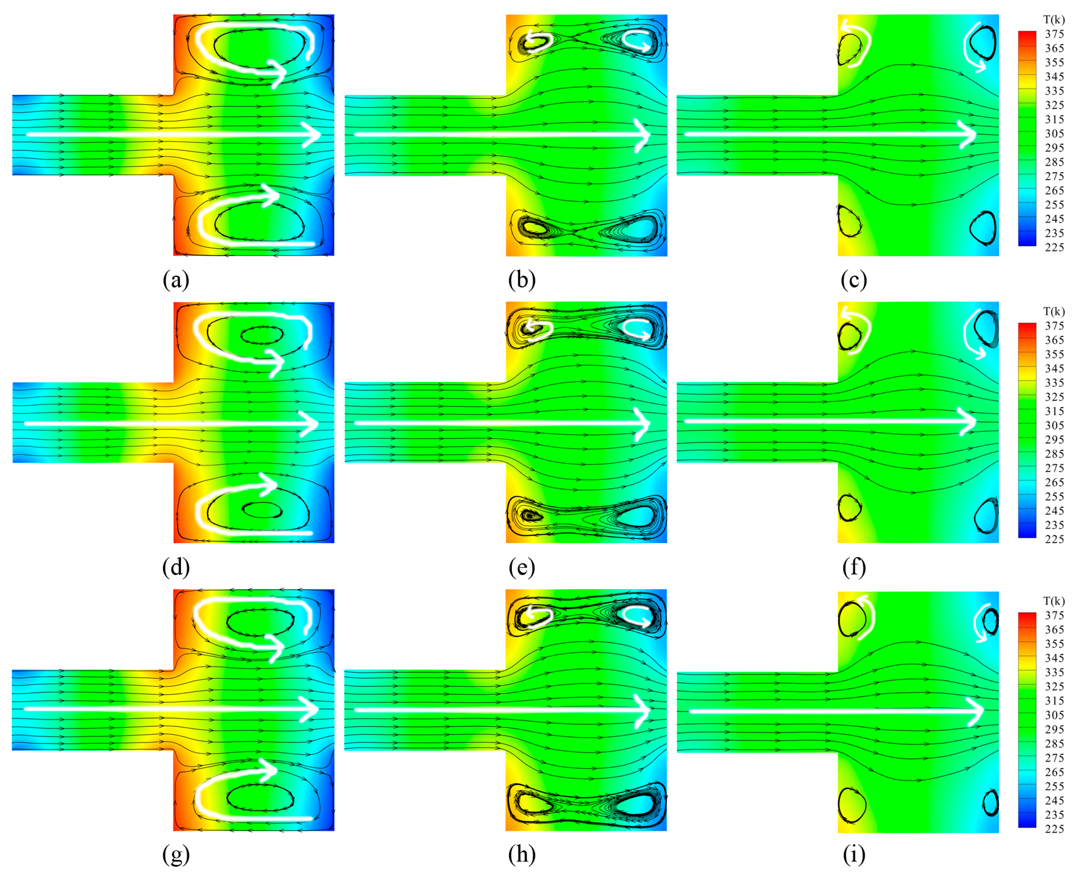
3.1. Velocity and Temperature Distribution
3.2. Temperature Gradient
3.3. Mean Velocity
3.4. Mass Flow Rate
4. Conclusions
Author Contributions
Funding
Acknowledgments
Conflicts of Interest
References
- Knudsen, M. Eine revision der gleichgewichtsbedingung der gase. Thermische Molekularströmung. Ann. Phys. 1909, 336, 205–229. [Google Scholar] [CrossRef]
- Nakaye, S.; Sugimoto, H. Demonstration of a gas separator composed of Knudsen pumps. Vacuum 2016, 125, 154–164. [Google Scholar] [CrossRef]
- Nakaye, S.; Sugimoto, H.; Gupta, N.K.; Gianchandani, Y.B. Thermal method of gas separation with micro-pores. In Proceedings of the 2014 IEEE SENSORS, Valencia, Spain, 2–5 November 2014; pp. 815–818. [Google Scholar]
- Terry, S.C.; Jerman, J.H.; Angell, J.B. A gas chromatographic air analyzer fabricated on a silicon wafer. IEEE Trans. Electron. Devices 1979, 26, 1880–1886. [Google Scholar] [CrossRef]
- Ferran, R.J.; Boumsellek, S. High-pressure effects in miniature arrays of quadrupole analyzers for residual gas analysis from 10-9 to 10-2 Torr. J. Vac. Sci. Technol. A-Vac. Surf. Films 1996, 14, 1258–1265. [Google Scholar] [CrossRef]
- Blomberg, M.; Rusanen, O.; Keranen, K.; Lehto, A. A silicon microsystem-miniaturised infrared spectrometer. In Proceedings of the International Conference on Solid State Sensors and Actuators, Chicago, IL, USA, 19 June 1997; pp. 1257–1258. [Google Scholar]
- Fu, K.; Knobloch, A.J.; Cooley, B.A.; Walther, D.C.; Fernandez-Pello, C.; Liepmann, D.; Miyasaka, K. Microscale Combustion Research for Applications to MEMS Rotary IC Engine. In Proceedings of the ASME 35th National Heat Transfer Conference, Anaheim, CA, USA, 10–12 June 2001. [Google Scholar]
- Yang, W.M.; Chou, S.K.; Shu, C.; Li, Z.W.; Xue, H. Combustion in micro-cylindrical combustors with and without a backward facing step. Appl. Therm. Eng. 2002, 22, 1777–1787. [Google Scholar] [CrossRef]
- Wei, S.; Berg, M.; Ljungqvist, D. Flapping and flexible wings for biological and micro air vehicles. Prog. Aeosp. Sci. 1999, 35, 455–505. [Google Scholar]
- Ellington, C.P. The novel aerodynamics of insect flight: Applications to micro-air vehicles. J. Exp. Biol. 1999, 202, 3439–3448. [Google Scholar]
- Zhao, S.; Jiang, B.; Maeder, T.; Muralt, P.; Kim, N.; Matam, S.K.; Jeong, E.; Han, Y.L.; Koebel, M.M. Dimensional and Structural Control of Silica Aerogel Membranes for Miniaturized Motionless Gas Pumps. ACS Appl. Mater. Interfaces 2015, 7, 18803–18814. [Google Scholar] [CrossRef] [PubMed]
- Vargo, S.E.; Muntz, E.P. Initial results from the first MEMS fabricated thermal transpiration-driven vacuum pump. Am. Inst. Phys. 2001, 585, 502–509. [Google Scholar]
- Young, M.; Han, Y.L.; Muntz, E.P.; Shiflett, G. Characterization and Optimization of a Radiantly Driven Multi-Stage Knudsen Compressor. In Proceedings of the RAREFIED GAS DYNAMICS: 24th International Symposium on Rarefied Gas Dynamics, Bari, Italy, 10–16 July 2004; American Institute of Physics: College Park, MD, USA, 2005; pp. 174–179. [Google Scholar]
- Nakaye, S.; Sugimoto, H.; Gupta, N.K.; Gianchandani, Y.B. Thermally enhanced membrane gas separation. Eur. J. Mech. B-Fluids 2015, 49, 36–49. [Google Scholar] [CrossRef]
- Gupta, N.K.; Gianchandani, Y.B. Thermal transpiration in zeolites: A mechanism for motionless gas pumps. Appl. Phys. Lett. 2008, 93, 193511. [Google Scholar] [CrossRef]
- Gupta, N.K.; Gianchandani, Y.B. A knudsen pump using nanoporous zeolite for atmospheric pressure operation. In Proceedings of the IEEE International Conference on Micro Electro Mechanical Systems (MEMS), Wuhan, China, 13–17 January 2008; pp. 38–41. [Google Scholar]
- Han, Y.L.; Young, M.; Muntz, E.P. Performance of Micro/Meso-Scale Thermal Transpiration Pumps at Low Pressures. In Proceedings of the ASME 2004 International Mechanical Engineering Congress and Exposition, Anaheim, CA, USA, 13–19 November 2004; pp. 257–265. [Google Scholar]
- Han, Y.L.; Young, M.; Muntz, E.P.; Shiflett, G. Knudsen compressor performance at low pressures. In Proceedings of the AIP Conference, Rio de Janeiro, Brazil, 23–25 May 2005; pp. 162–167. [Google Scholar]
- Faiz, A.; McNamara, S.; Bell, A.D.; Sumanasekera, G. Nanoporous Bi2Te3 thermoelectric based Knudsen gas pump. J. Micromech. Microeng. 2014, 24, 035002. [Google Scholar] [CrossRef]
- Goldsmid, H.J.; Douglas, R.W. The use of semiconductors in thermoelectric refrigeration. Br. J. Appl. Phys. 1954, 5, 386. [Google Scholar] [CrossRef]
- Bond, D.M.; Wheatley, V.; Goldsworthy, M. Numerical investigation into the performance of alternative Knudsen pump designs. Int. J. Heat Mass Transf. 2016, 93, 1038–1058. [Google Scholar] [CrossRef]
- Bond, D.M.; Wheatley, V.; Goldsworthy, M. Numerical investigation of curved channel Knudsen pump performance. Int. J. Heat Mass Transf. 2014, 76, 1–15. [Google Scholar] [CrossRef]
- Aoki, K.; Degond, P.; Mieussens, L.; Takata, S.; Yoshida, H. A diffusion model for rarefied flows in curved channels. Multiscale Model. Multiscale Model. Simul. 2008, 6, 1281–1316. [Google Scholar] [CrossRef]
- Aoki, K.; Degond, P.; Mieussens, L. Numerical simulations of rarefied gases in curved channels: Thermal creep, circulating flow, and pumping effect. Commun. Comput. Phys. 2009, 6, 919–954. [Google Scholar] [CrossRef]
- Tatsios, G.; Quesada, G.L.; Rojas-Cardenas, M.; Baldas, L.; Colin, S.; Valougeorgis, D. Computational investigation and parametrization of the pumping effect in temperature-driven flows through long tapered channels. Microfluid. Nanofluid. 2017, 21, 99. [Google Scholar] [CrossRef]
- Würger, A. Leidenfrost gas ratchets driven by thermal creep. Phys. Rev. Lett. 2011, 107, 164502. [Google Scholar] [CrossRef]
- Chen, J.; Baldas, L.; Colin, S. Numerical study of thermal creep flow between two ratchet surfaces. Vacuum 2014, 109, 294–301. [Google Scholar] [CrossRef]
- Chen, J.; Stefanov, S.K.; Baldas, L.; Colin, S. Analysis of flow induced by temperature fields in ratchet-like microchannels by Direct Simulation Monte Carlo. Int. J. Heat Mass Transf. 2016, 99, 672–680. [Google Scholar] [CrossRef]
- Shahabi, V.; Baier, T.; Roohi, E.; Hardt, S. Thermally induced gas flows in ratchet channels with diffuse and specular boundaries. Sci Rep 2017, 7, 41412. [Google Scholar] [CrossRef] [PubMed]
- Kuddusi, L.; Çetegen, E. Thermal and hydrodynamic analysis of gaseous flow in trapezoidal silicon microchannels. Int. J. Therm. Sci. 2009, 48, 353–362. [Google Scholar] [CrossRef]
- Gatignol, R.; Croizet, C. Asymptotic modeling of thermal binary monatomic gas flows in plane microchannels—Comparison with DSMC simulations. Phys. Fluids 2017, 29, 042001. [Google Scholar] [CrossRef]
- Taheri, P.; Torrilhon, M.; Struchtrup, H. Couette and Poiseuille microflows: Analytical solutions for regularized 13-moment equations. Phys. Fluids 2009, 21, 7593. [Google Scholar] [CrossRef]
- Bhatnagar, P.L.; Gross, E.P.; Krook, M. A model for collision processes in gases. I. Small amplitude processes in charged and neutral one-component systems. Phys. Rev. 1954, 94, 511–525. [Google Scholar] [CrossRef]
- McCormack, F.J. Construction of linearized kinetic models for gaseous mixtures and molecular gases. Phys. Fluids 1973, 16, 2095–2105. [Google Scholar] [CrossRef]
- Sharipov, F.; Kalempa, D. Gaseous mixture flow through a long tube at arbitrary Knudsen numbers. J. Vac. Sci. Technol. A-Vac. Surf. Films 2002, 20, 814–822. [Google Scholar] [CrossRef]
- Naris, S.; Valougeorgis, D.; Kalempa, D.; Sharipov, F. Flow of gaseous mixtures through rectangular microchannels driven by pressure, temperature, and concentration gradients. Phys. Fluids 2005, 17, 100607. [Google Scholar] [CrossRef]
- Szalmás, L. Flows of rarefied gaseous mixtures in networks of long channels. Microfluid. Nanofluid. 2013, 15, 817–827. [Google Scholar] [CrossRef]
- Bird, G.A. Molecular Gas Dynamics; Clarendon Press: Gloucestershire, UK, 1976. [Google Scholar]
- Bird, G.A. Monte Carlo simulation of gas flows. Annu. Rev. Fluid Mech. 1978, 10, 11–31. [Google Scholar] [CrossRef]
- Bird, G.A. Molecular Gas Dynamics and the Direct Simulation Monte Carlo of Gas Flows; Clarendon Press: Gloucestershire, UK, 1994; Volume 508, p. 128. [Google Scholar]
- Sharipov, F. Gaseous mixtures in vacuum systems and microfluidics. J. Vac. Sci. Technol. A-Vac. Surf. Films 2013, 31, 050806. [Google Scholar] [CrossRef]
- Wang, R.; Xu, X.; Xu, K.; Qian, T. Onsager’s cross coupling effects in gas flows confined to micro-channels. Phys. Rev. Fluids 2016, 1, 044102. [Google Scholar] [CrossRef]
- Zhu, L.; Chen, S.; Guo, Z. dugksFoam: An open source OpenFOAM solver for the Boltzmann model equation. Comput. Phys. Commun. 2017, 213, 155–164. [Google Scholar] [CrossRef]
- Zhu, L.; Yang, X.; Guo, Z. Thermally induced rarefied gas flow in a three-dimensional enclosure with square cross-section. Phys. Rev. Fluids 2017, 2, 123402. [Google Scholar] [CrossRef]
- Zhu, L.; Guo, Z. Numerical study of nonequilibrium gas flow in a microchannel with a ratchet surface. Phys. Rev. E 2017, 95, 023113. [Google Scholar] [CrossRef] [PubMed]
- Lotfian, A.; Roohi, E. Radiometric flow in periodically patterned channels: fluid physics and improved configurations. J. Fluid Mech. 2019, 860, 544–576. [Google Scholar] [CrossRef]
- Prasanth, P.S.; Kakkassery, J.K. Direct simulation Monte Carlo (DSMC): A numerical method for transition-regime flows-A review. J. Indian Inst. Sci. 2013, 86, 169. [Google Scholar]
- Liou, W.W.; Fang, Y. Heat transfer in microchannel devices using dsmc. J. Microelectromech. Syst. 2001, 10, 274–279. [Google Scholar] [CrossRef]
- Ye, J.; Yang, J.; Zheng, J.; Xu, P.; Lam, C.; Wong, I.; Ma, Y. Effects of wall temperature on the heat and mass transfer in microchannels using the DSMC method. In Proceedings of the International Conference on Nano/Micro Engineered and Molecular Systems, Shenzhen, China, 5–8 January 2009; pp. 666–671. [Google Scholar]
- Tantos, C.; Valougeorgis, D.; Pannuzzo, M.; Frezzotti, A.; Morini, G.L. Conductive heat transfer in a rarefied polyatomic gas confined between coaxial cylinders. Int. J. Heat Mass Transf. 2014, 79, 378–389. [Google Scholar] [CrossRef]
- Szalmas, L.; Valougeorgis, D.; Colin, S. DSMC simulation of pressure driven binary rarefied gas flows through short microtubes. In Proceedings of the ASME 2011 9th International Conference on Nanochannels, Microchannels, and Minichannels, Edmonton, AB, Canada, 19–22 June 2011; pp. 279–288. [Google Scholar]
- Vargas, M.; Stefanov, S.; Roussinov, V. Transient heat transfer flow through a binary gaseous mixture confined between coaxial cylinders. Int. J. Heat Mass Transf. 2013, 59, 302–315. [Google Scholar] [CrossRef]
- Zade, A.Q.; Ahmadzadegan, A.; Renksizbulut, M. A detailed comparison between navier-stokes and dsmc simulations of multicomponent gaseous flow in microchannels. Int. J. Heat Mass Transf. 2012, 55, 46734681. [Google Scholar]
- Sugimoto, H.; Shinotou, A. Gas separator with the thermal transpiration in a rarefied gas. In Proceedings of the AIP Conference Proceedings, Pacific Grove, CA, USA, 10–15 July 2010; pp. 784–789. [Google Scholar]
- Han, Y.L. Thermal-creep-driven flows in knudsen compressors and related nano/microscale gas transport channels. J. Microelectromech. Syst. 2008, 17, 984–997. [Google Scholar]
- Scanlon, T.J.; Roohi, E.; White, C.; Darbandi, M.; Reese, J.M. An open source, parallel DSMC code for rarefied gas flows in arbitrary geometries. Comput. Fluids 2010, 39, 2078–2089. [Google Scholar] [CrossRef]
- Prasanth, P.S.; Kakkassery, J.K. Molecular models for simulation of rarefied gas flows using direct simulation monte carlo method. Fluid Dyn. Res. 2008, 40, 233–252. [Google Scholar] [CrossRef]
- White, C.; Borg, M.K.; Scanlon, T.J.; Longshaw, S.M.; John, B.; Emerson, D.R.; Reese, J.M. dsmcFoam+: An OpenFOAM based direct simulation Monte Carlo solver. Comput. Phys. Commun. 2018, 224, 22–43. [Google Scholar] [CrossRef]
- Gallis, M.A.; Torczynski, J.R.; Rader, D.J.; Bird, G.A. Convergence behavior of a new DSMC algorithm. J. Comput. Phys. 2009, 228, 4532–4548. [Google Scholar] [CrossRef]
- Kosuge, S.; Takata, S. Database for flows of binary gas mixtures through a plane microchannel. Eur. J. Mech. B-Fluids 2008, 27, 444–465. [Google Scholar] [CrossRef]


| Parameter | Case 1 | Case 2 | Case 3 | Case 4 | Case 5 | Case 6 |
|---|---|---|---|---|---|---|
| Number of the cell NC | 9248 | 5100 | 3200 | 3200 | 3200 | 3200 |
| 10/63 | 5/24 | 1/3 | 1/3 | 1/3 | 1/3 | |
| The number of the simulator in the cell n | 15 | 15 | 10 | 15 | 20 | 30 |
| Time step (s) | 4 × 10⁻¹¹ | 5 × 10⁻¹¹ | 1 × 10⁻¹⁰ | 1 × 10⁻¹⁰ | 1 × 10⁻¹⁰ | 1 × 10⁻¹⁰ |
| Mass flow rate (10−11) (kg/s) | 3.8294 | 3.8328 | 3.8681 | 3.8367 | 3.8359 | 3.8384 |
| Gas | Property | |||
|---|---|---|---|---|
| Molecular Mass m (10−27) (kg) | Molecular Diameter d (10−10) (m) | Internal Degree of Freedom | ||
| N2 | 46.50 | 4.17 | 2 | 0.74 |
| O2 | 53.12 | 4.07 | 2 | 0.77 |
© 2019 by the authors. Licensee MDPI, Basel, Switzerland. This article is an open access article distributed under the terms and conditions of the Creative Commons Attribution (CC BY) license (http://creativecommons.org/licenses/by/4.0/).
Share and Cite
Zhang, Z.; Wang, X.; Zhao, L.; Zhang, S.; Zhao, F. Study of Flow Characteristics of Gas Mixtures in a Rectangular Knudsen Pump. Micromachines 2019, 10, 79. https://doi.org/10.3390/mi10020079
Zhang Z, Wang X, Zhao L, Zhang S, Zhao F. Study of Flow Characteristics of Gas Mixtures in a Rectangular Knudsen Pump. Micromachines. 2019; 10(2):79. https://doi.org/10.3390/mi10020079
Chicago/Turabian StyleZhang, Zhijun, Xiaowei Wang, Lili Zhao, Shiwei Zhang, and Fan Zhao. 2019. "Study of Flow Characteristics of Gas Mixtures in a Rectangular Knudsen Pump" Micromachines 10, no. 2: 79. https://doi.org/10.3390/mi10020079
APA StyleZhang, Z., Wang, X., Zhao, L., Zhang, S., & Zhao, F. (2019). Study of Flow Characteristics of Gas Mixtures in a Rectangular Knudsen Pump. Micromachines, 10(2), 79. https://doi.org/10.3390/mi10020079