Ultra-Sensitive Flexible Tactile Sensor Based on Graphene Film

 , ,
, ,
Abstract
1. Introduction
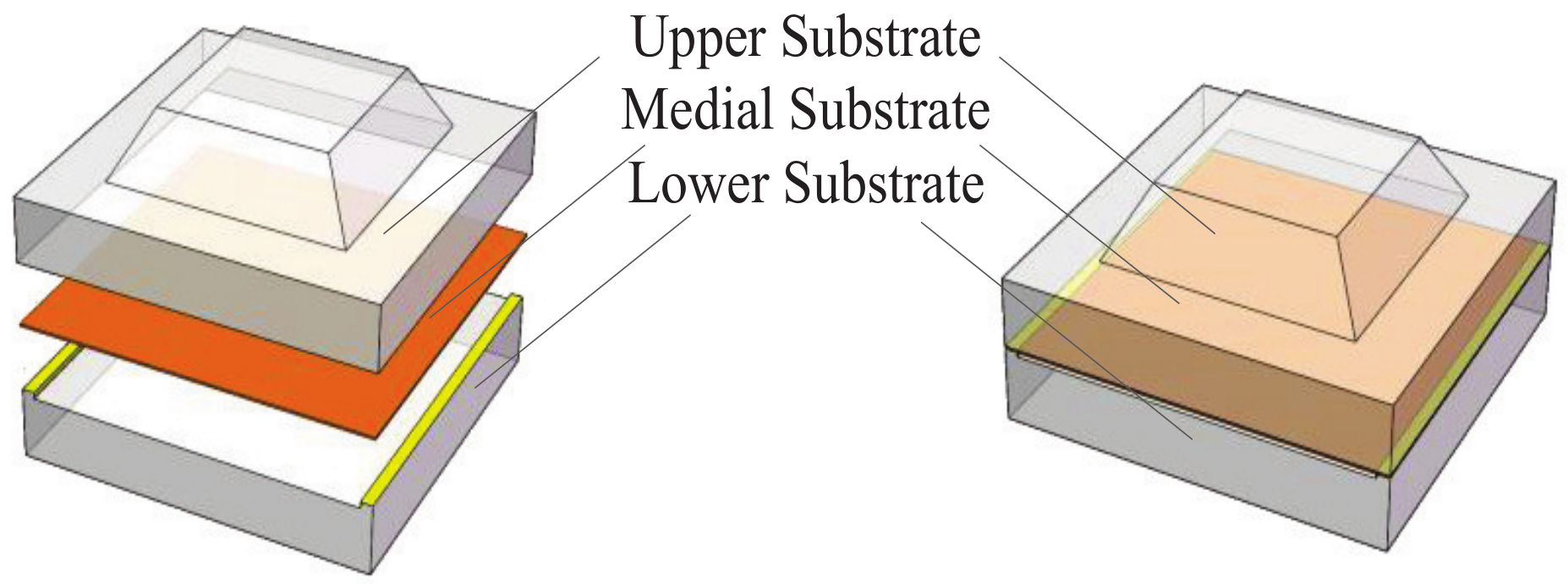
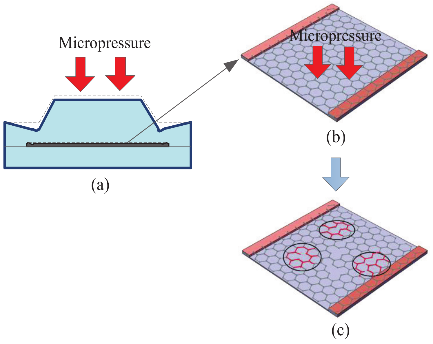
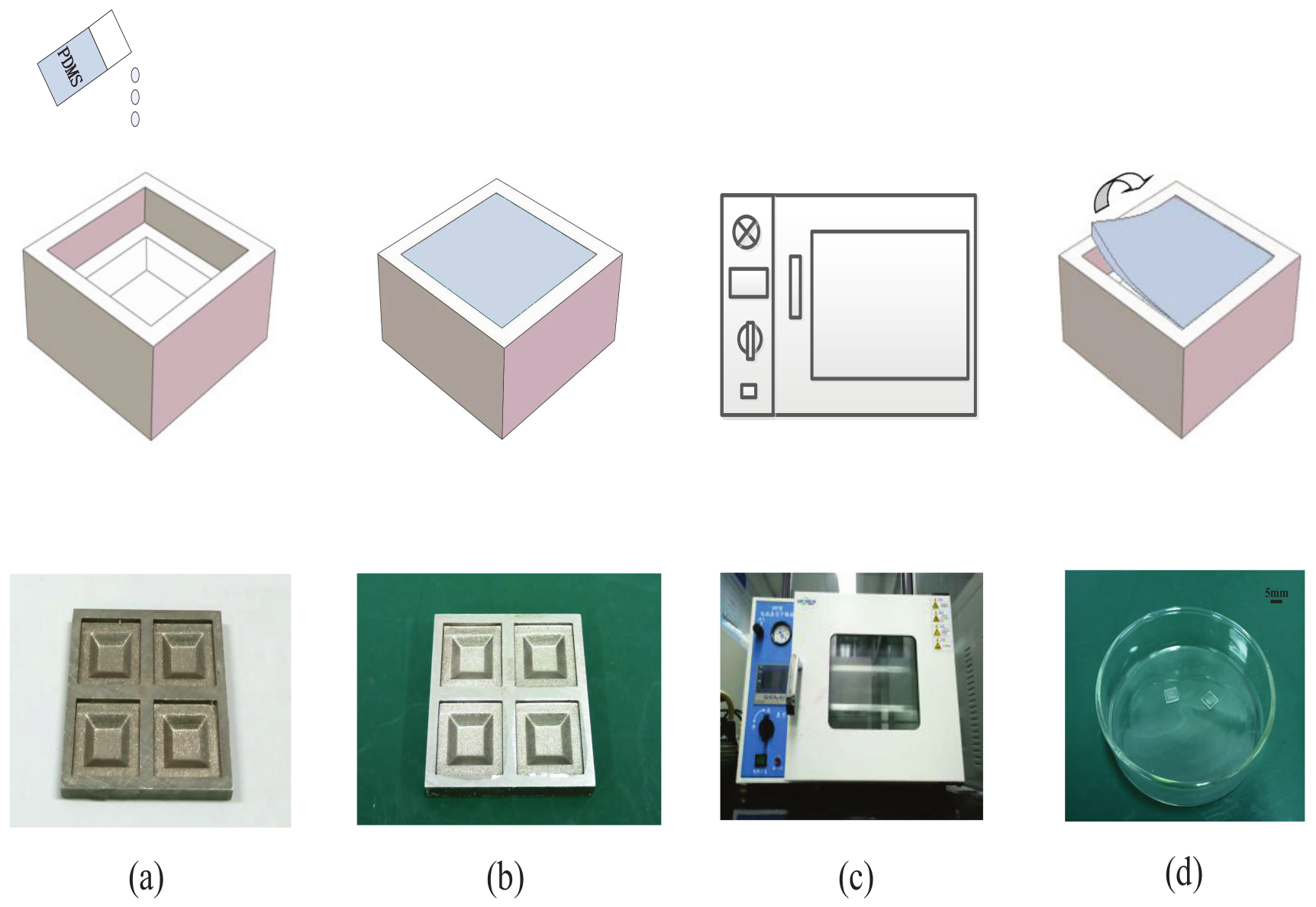
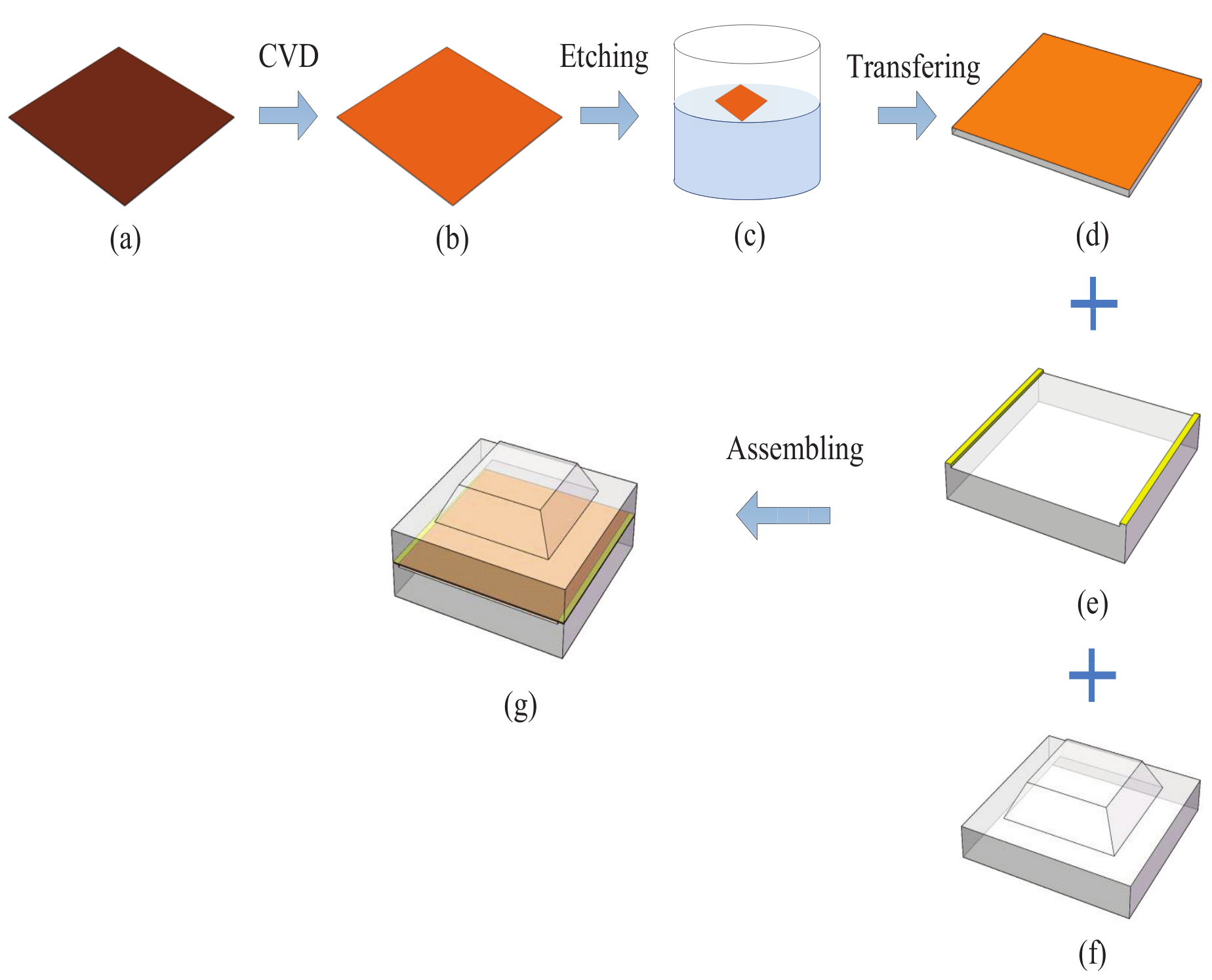
2. Method
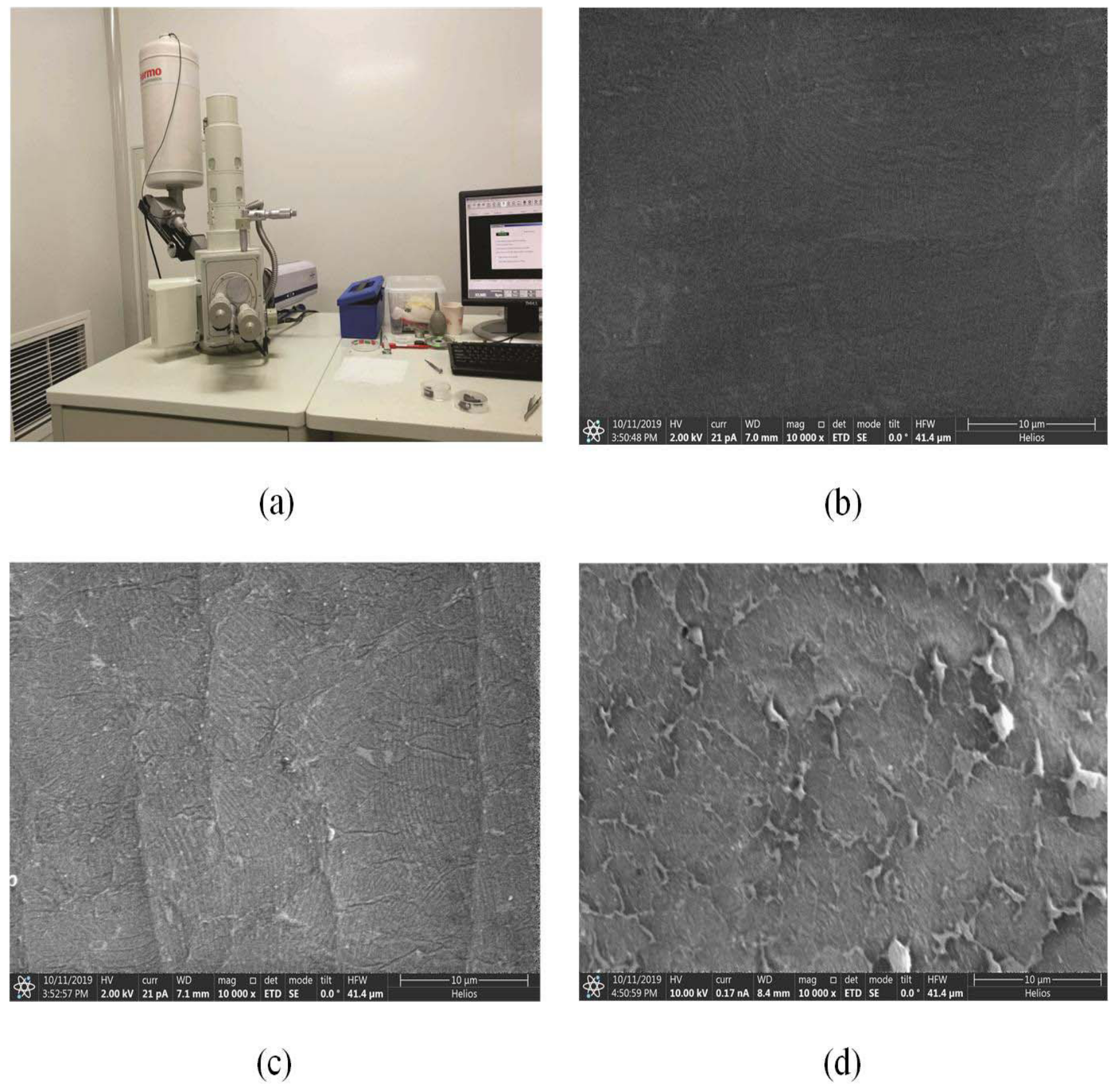
3. Material
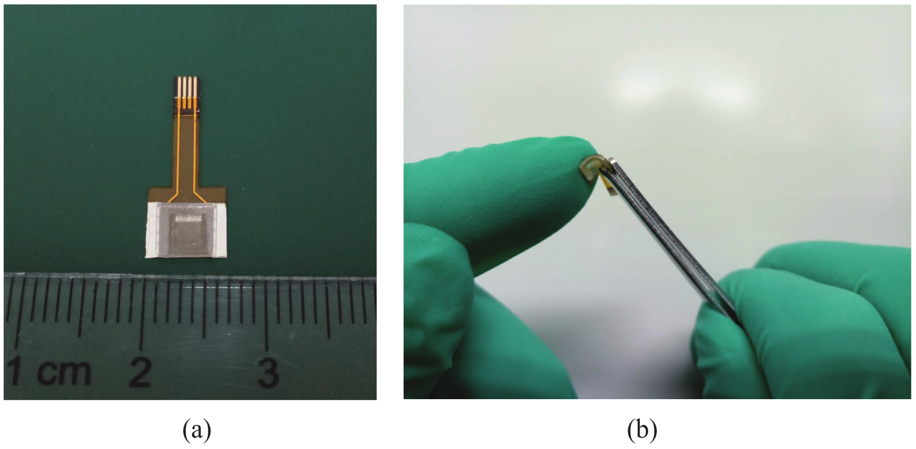
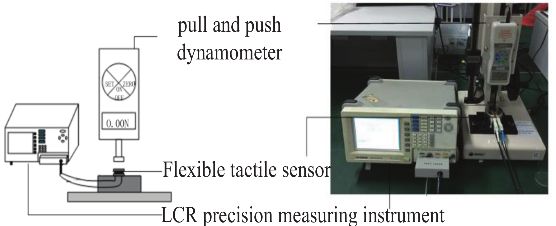
4. Experimental
5. Results and Discussion
5.1. Performance
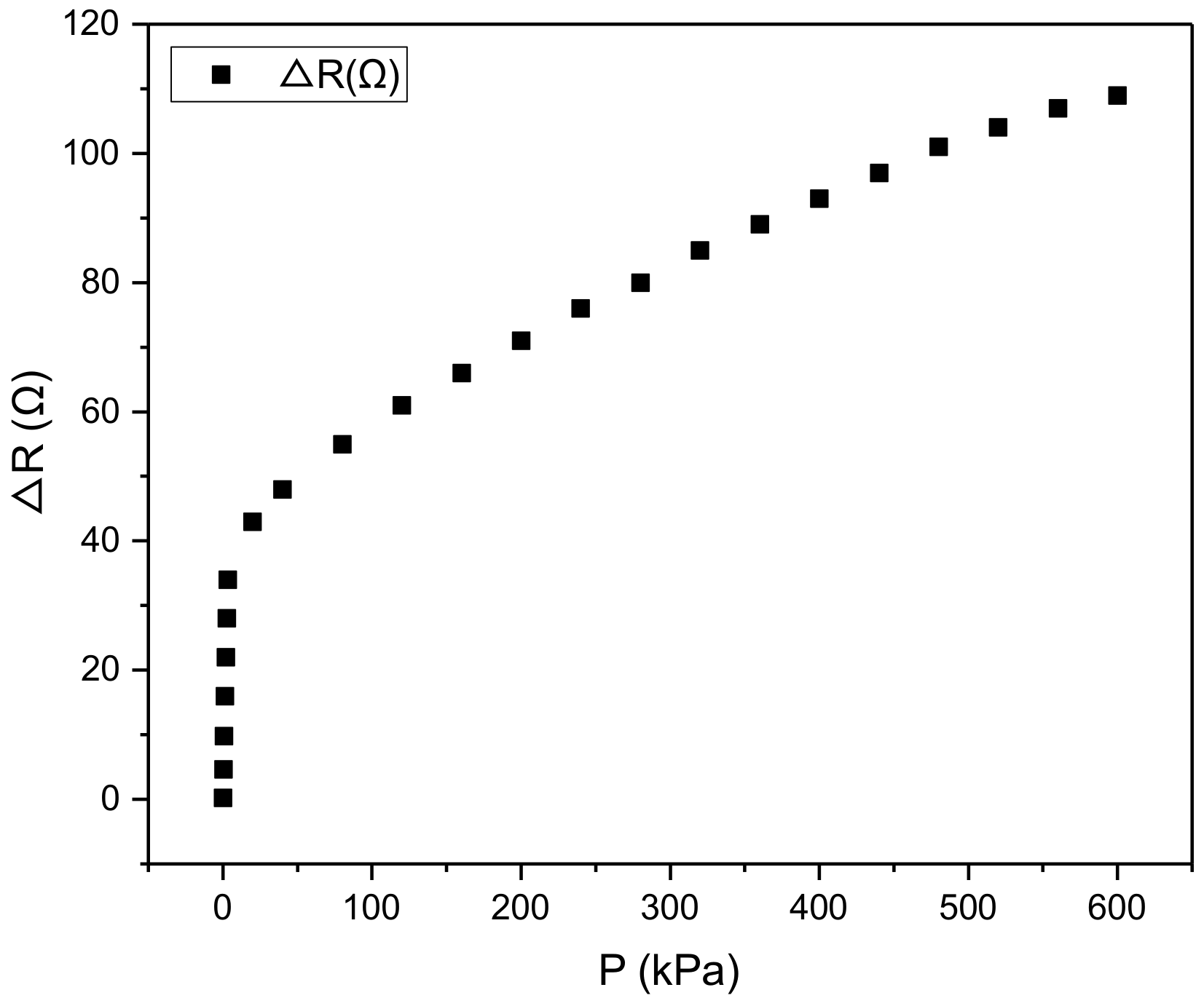
5.2. Sensitivity
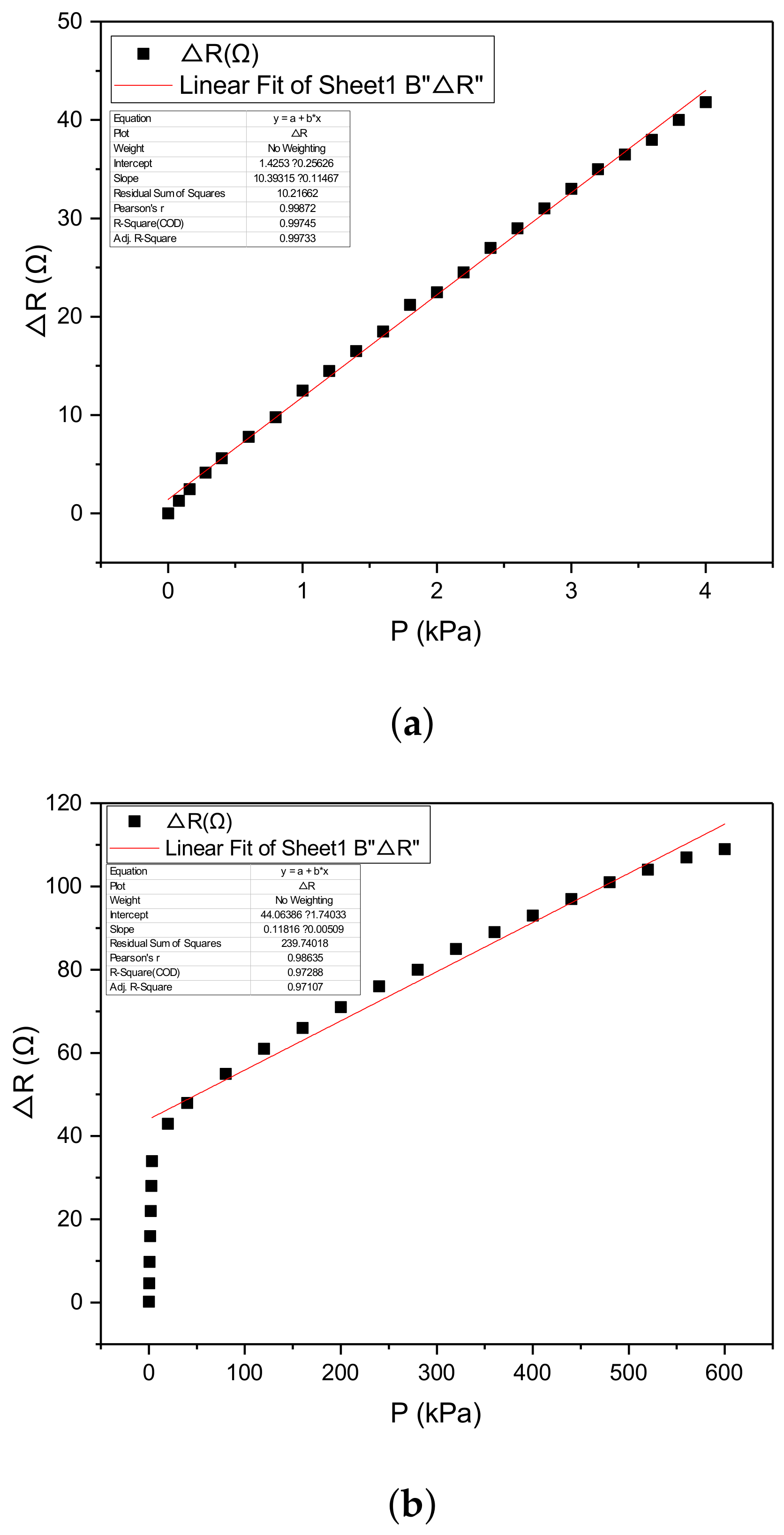
5.3. Linearity
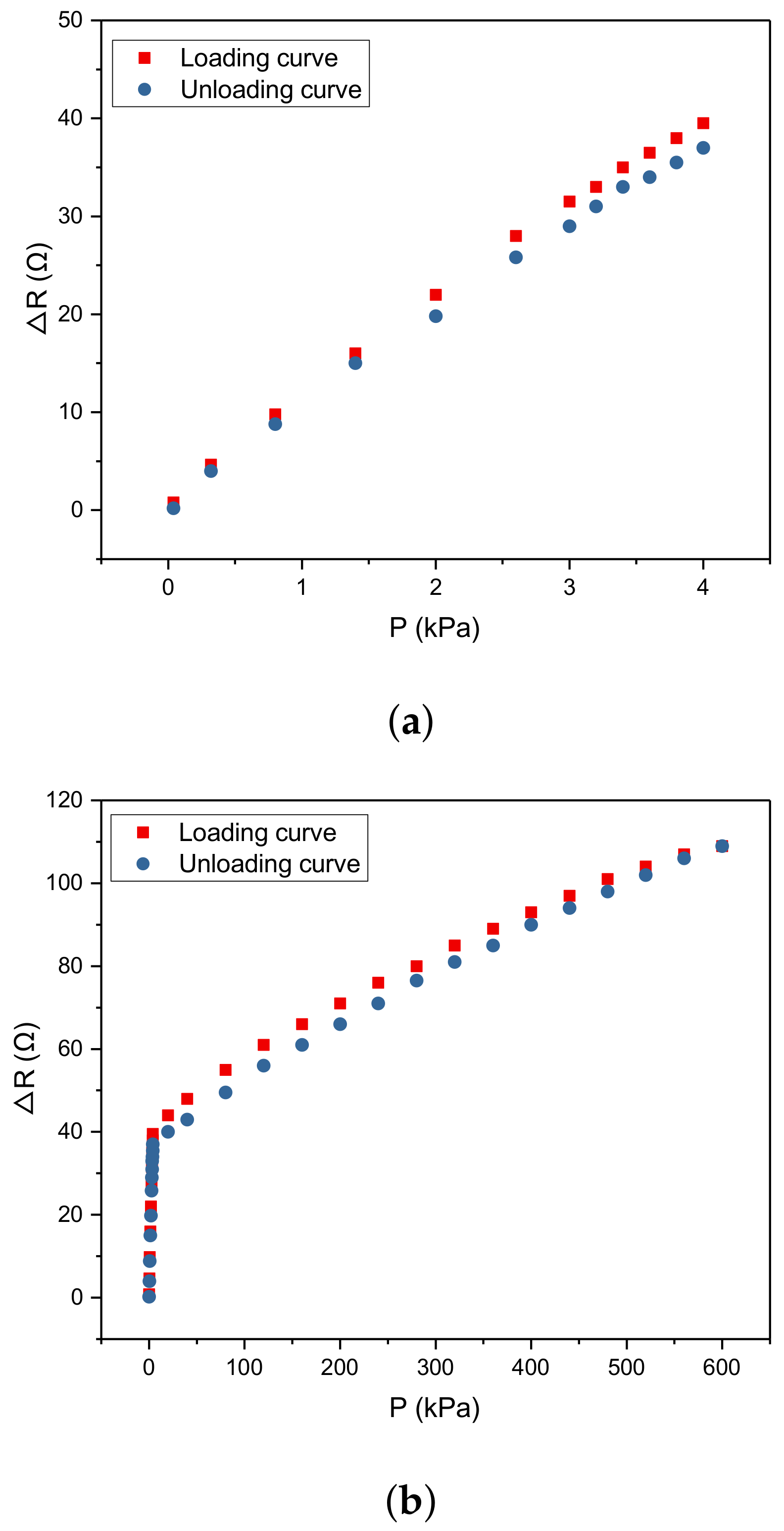
5.4. Hysteresis
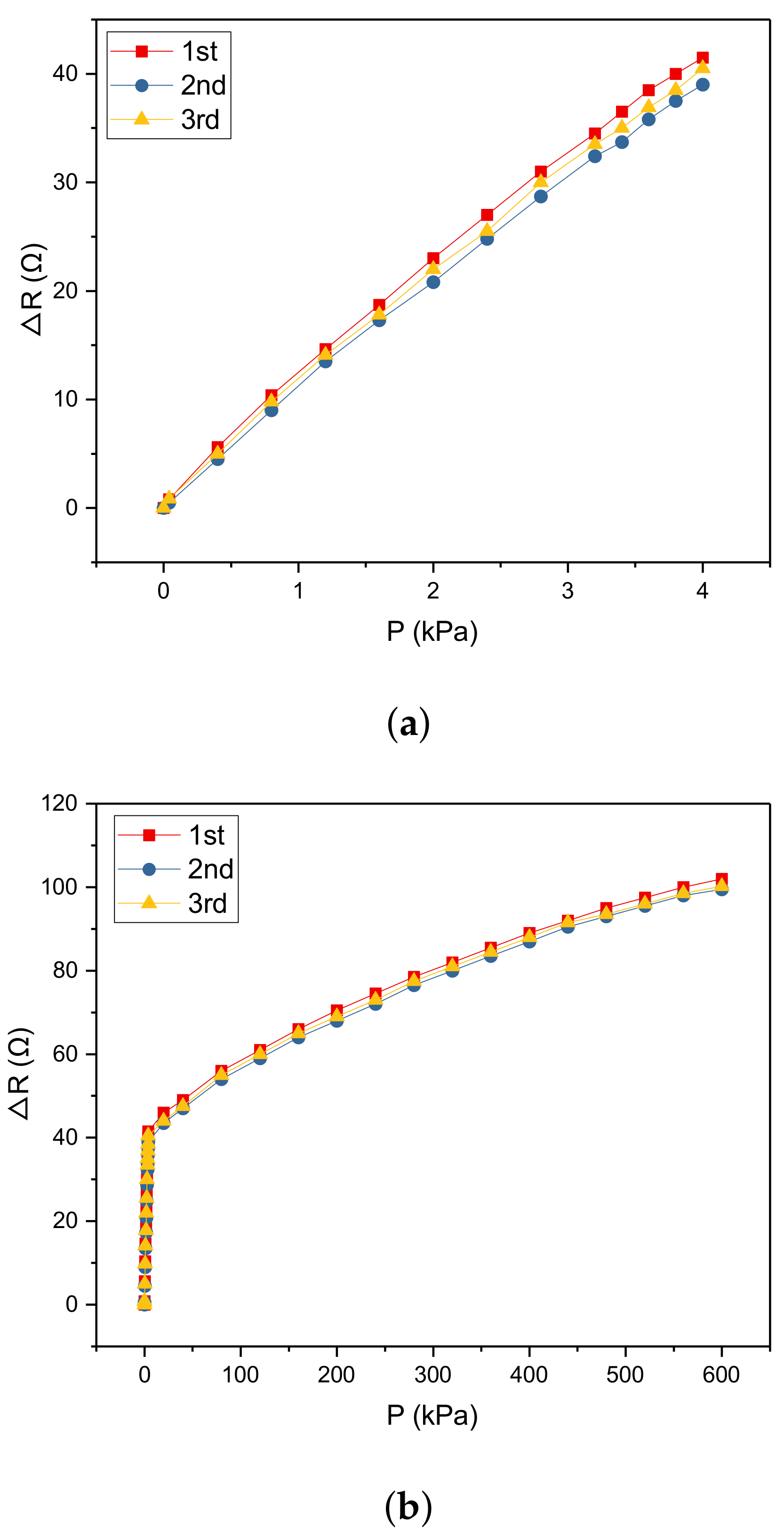
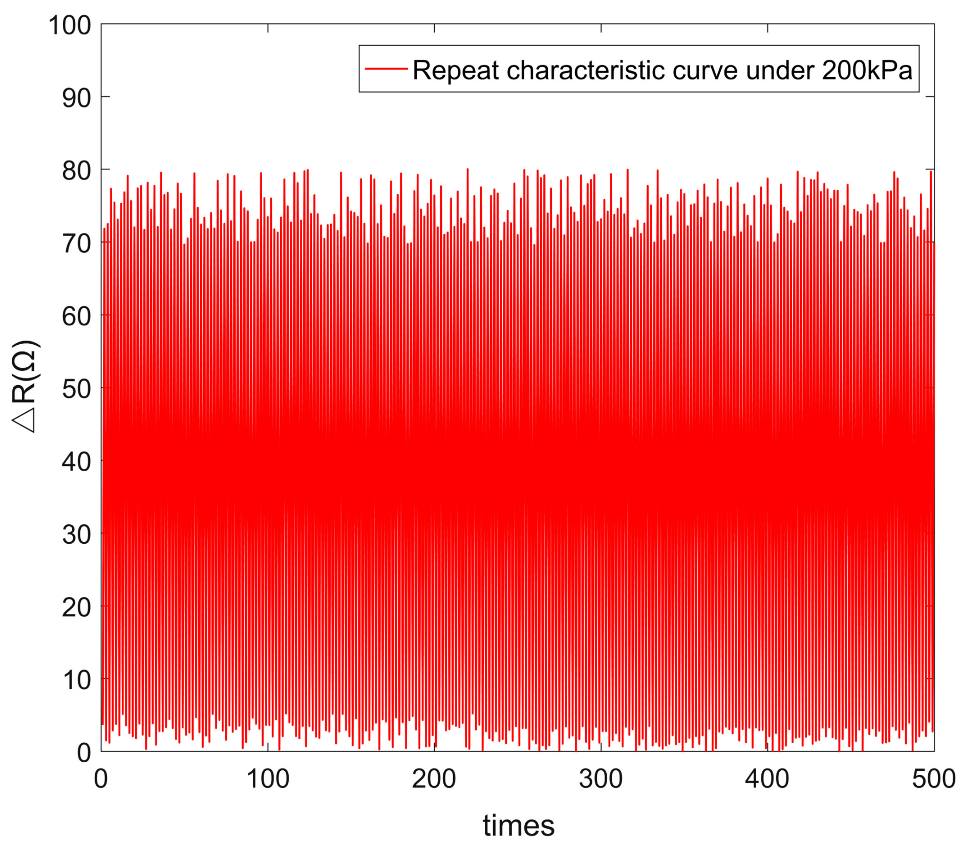
5.5. Repeatability
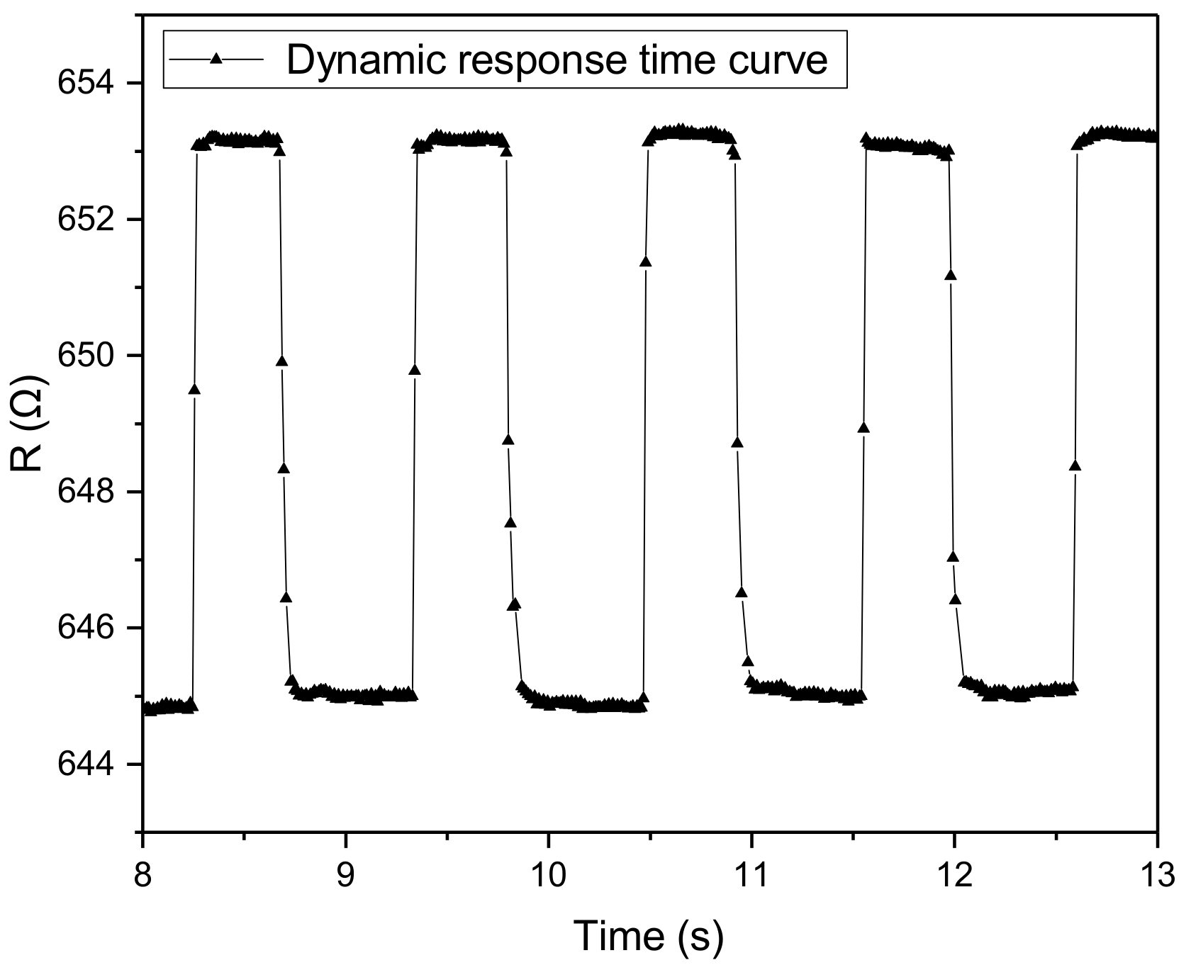
5.6. Dynamic Performance
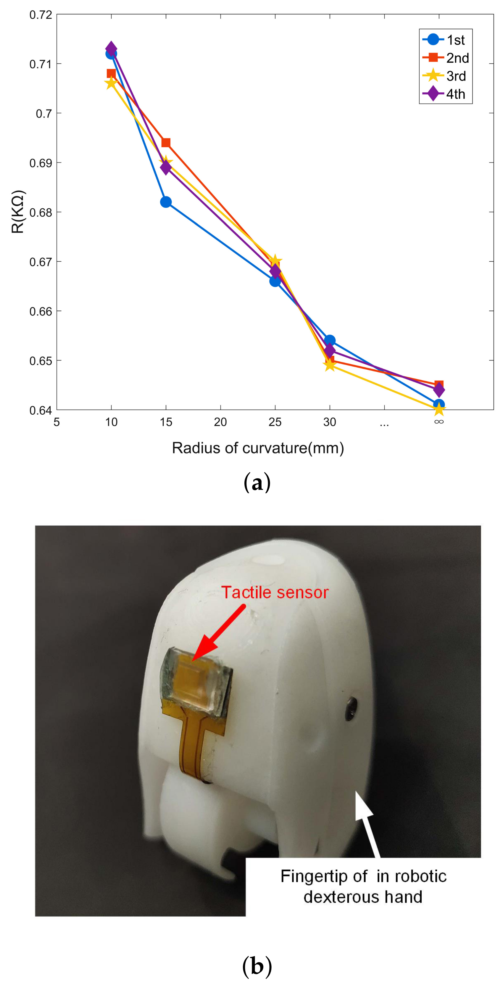
5.7. Flexibility
5.8. Sensors Comparisone
6. Conclusions
Author Contributions
Funding
Conflicts of Interest
References
- Novoselov, K.S.; Geim, A.K.; Morozov, S.V.; Jiang, D.; Zhang, Y.; Dubonos, S.V.; Grigorieva, I.V.; Firsov, A.A. Electric field effect in atomically thin carbon films. Science 2004, 306, 666–669. [Google Scholar] [CrossRef] [PubMed]
- Huang, Y.; Yuan, H.; Kan, W.; Guo, X.; Liu, C.; Liu, P. A fexible three-axial capacitive tactile sensor with multilayered dielectric for artifcial skin applications. Microsyst. Technol. 2017, 23, 1847–1852. [Google Scholar] [CrossRef]
- Chen, L.; Liu, J.; Wang, X.; Ji, B.; Chen, X.; Yang, B. Flexible Capacitive Hydrogel Tactile Sensor With Adjustable Measurement Range Using Liquid Crystal and Carbon Nanotubes Composites. IEEE Trans. Electron Devices 2017, 64, 1968–1972. [Google Scholar] [CrossRef]
- Wan, S.; Bi, H.; Zhou, Y.; Xie, X.; Su, S.; Yin, K.; Sun, L. Graphene oxide as high-performance dielectric materials for capacitive pressure sensors. Carbon 2017, 114, 209–216. [Google Scholar] [CrossRef]
- Yu, P.; Liu, W.; Gu, C.; Cheng, X.; Fu, X. Flexible Piezoelectric Tactile Sensor Array for Dynamic Three-Axis Force Measureme. Sensors 2016, 16, 819. [Google Scholar] [CrossRef] [PubMed]
- Yu, P.; Liu, W.; Gu, C.; Cheng, X.; Fu, X. Fingertip Piezoelectric Tactile Sensor Array for Roughness Encoding Under Varying Scanning Velocity. IEEE Sens. J. 2017, 17, 6867–6879. [Google Scholar]
- Sim, M.; Jeong, Y.; Lee, K.; Shin, K.; Park, H.; Sohn, J.I.; Cha, S.N.; Jang, J.E. Psychological tactile sensor structure based on piezoelectric sensor arrays. RSC Adv. 2015, 5, 40363–40368. [Google Scholar]
- Hoang, P.T.; Phung, H.; Nguyen, C.T.; Nguyen, T.D.; Choi, H.R. A Highly Flexible, Stretchable and Ultra-thin Piezoresistive Tactile Sensor Array using PAM/PEDOT:PSS Hydrogel. In Proceedings of the International Conference on Ubiquitous Robots and Ambient Intelligence (URAI), Jeju, Korea, 28 June–1 July 2017; pp. 950–955. [Google Scholar]
- Shi, J.; Hu, J.; Dai, Z.; Zhao, W.; Liu, P.; Zhao, L.; Guo, Y.; Yang, T.; Zou, L.; Li, H.; et al. Graphene welded carbon nanotube crossbars for biaxial strain sensors. Carbon 2017, 123, 786–793. [Google Scholar] [CrossRef]
- Luo, Y.; Xiao, Q.; Li, B. A Stretchable Pressure-Sensitive Array Based on Polymer Matrix. Sensors 2017, 123, 786–793. [Google Scholar]
- Huang, Y.; He, X.; Gao, L.; Wang, Y.; Liu, C.; Liu, P. Pressure-sensitive carbon black graphene nanoplatelets silicone rubber hybrid conductive composites based on a three-dimensional polydopamine-modified polyurethane sponge. J. Mater. Sci. Mater. Electron. 2017, 28, 9495–9504. [Google Scholar] [CrossRef]
- Wei, Y.; Chen, S.; Dong, X.; Lin, Y.; Liu, L. Flexible piezoresistive sensors based on dynamic bridging effect of silver nanowires toward graphene. Carbon 2017, 113, 395–403. [Google Scholar] [CrossRef]
- Xu, M.; Qi, J.; Li, F.; Liao, X.; Liu, S.; Zhang, Y. Ultra-thin, transparent and flexible tactile sensors based on graphene films with excellent anti-interference. RSC Adv. 2017, 7, 30506–30512. [Google Scholar] [CrossRef]
- Lipomi, D.J.; Vosgueritchian, M.; Tee, B.C.; Hellstrom, S.L.; Lee, J.A.; Fox, C.H.; Bao, Z. Skin-like pressure and strain sensors based on transparentelastic films of carbon nanotubes. Nat. Nanotechnol. 2011, 6, 788–792. [Google Scholar] [CrossRef] [PubMed]
- Rinaldi, A.; Tamburrano, A.; Fortunato, M.; Sarto, M. A Flexible and Highly Sensitive Pressure Sensor Based on a PDMS Foam Coated with Graphene Nanoplatelets. Sensors 2016, 16, 2148. [Google Scholar] [CrossRef] [PubMed]
- Jung, Y.; Lee, D.G.; Park, J.; Ko, H.; Lim, H. Piezoresistive Tactile Sensor Discriminating Multidirectional Forces. Sensors 2015, 15, 25463–25473. [Google Scholar] [CrossRef] [PubMed]
- Lee, D.; Lee, H.; Jeong, Y.; Ahn, Y.; Nam, G.; Lee, Y. Highly Sensitive, Transparent, and Durable Pressure Sensors Based on Sea-Urchin ShapedMetal Nanoparticles. Adv. Mater. 2016, 28, 9364–9369. [Google Scholar] [CrossRef] [PubMed]
- Zhu, B.; Niu, Z.; Wang, H.; Leow, W.R.; Wang, H.; Li, Y.; Zheng, L.; Wei, J.; Huo, F.; Chen, X. Microstructured Graphene Arrays for Highly Sensitive Flexible Tactile Sensors. Small 2014, 10, 3625–3631. [Google Scholar] [CrossRef] [PubMed]
- Huang, Y.; Fang, D.; Wu, C.; Wang, W.; Guo, X.; Liu, P. A flexible touch-pressure sensor array withwireless transmission system for robotic skin. Rev. Svi. Instrum. 2017, 87, 065007. [Google Scholar] [CrossRef] [PubMed]
Sample Availability: Samples of the compounds are available from the authors. |


| Ref. | Material | Sensitivity (kPa) | Precision (kPa) | Measuring Range (kPa) | Span Scale | RT (ms) | Size (mm) |
|---|---|---|---|---|---|---|---|
| [12] | AgNWs/rGO | 5.8 | 0.000125 | 0–0.1 | 2 | 29.5 | |
| [16] | CNT/PDMS | 0.0173 | 0.128 | 0.128–44 | 2 | - | |
| [17] | ITO/SSNPs-PU/ITO | 2.46 | 0.3 | 0.3–24.5 | 1 | 30 | - |
| [18] | rGO | −5.53 | 0.0015 | 0-1 | 2 | 0.2 | |
| [19] | CNTs/CB/SR | > 0.04 | 0.1N | 0–1562.5 (0–100 N) | 3 | - | R = 4 |
| Our work | GR | 0.04 | 0.004 | 0–600 | 4 | 10 |
© 2019 by the authors. Licensee MDPI, Basel, Switzerland. This article is an open access article distributed under the terms and conditions of the Creative Commons Attribution (CC BY) license (http://creativecommons.org/licenses/by/4.0/).
Share and Cite
Lü, X.; Qi, L.; Hu, H.; Li, X.; Bai, G.; Chen, J.; Bao, W. Ultra-Sensitive Flexible Tactile Sensor Based on Graphene Film. Micromachines 2019, 10, 730. https://doi.org/10.3390/mi10110730
Lü X, Qi L, Hu H, Li X, Bai G, Chen J, Bao W. Ultra-Sensitive Flexible Tactile Sensor Based on Graphene Film. Micromachines. 2019; 10(11):730. https://doi.org/10.3390/mi10110730
Chicago/Turabian StyleLü, Xiaozhou, Liang Qi, Hanlun Hu, Xiaoping Li, Guanghui Bai, Jun Chen, and Weimin Bao. 2019. "Ultra-Sensitive Flexible Tactile Sensor Based on Graphene Film" Micromachines 10, no. 11: 730. https://doi.org/10.3390/mi10110730
APA StyleLü, X., Qi, L., Hu, H., Li, X., Bai, G., Chen, J., & Bao, W. (2019). Ultra-Sensitive Flexible Tactile Sensor Based on Graphene Film. Micromachines, 10(11), 730. https://doi.org/10.3390/mi10110730