Article

Shadow Spatiotemporal Track-Before-Detect Approach for Distributed UAV-Borne Video SAR

1
National Key Laboratory of Radar Signal Processing, Xidian University, Xi’an 710071, China
2
School of Electronic Engineering, Xidian University, Xi’an 710071, China
*
Author to whom correspondence should be addressed.
Remote Sens. 2026, 18(2), 343; https://doi.org/10.3390/rs18020343
Submission received: 18 December 2025 / Revised: 12 January 2026 / Accepted: 18 January 2026 / Published: 20 January 2026

Highlights

What are the main findings?
  • A dynamic programming-based spatiotemporal track-before-detect (TBD) algorithm is proposed to solve the problems of poor shadow-detection performance in complex scenarios and the limited adaptability of traditional DP-TBD to maneuvering targets.
  • A spatiotemporal cooperative shadow detection model is established based on a distributed video SAR system, including heterogeneous-view shadow association, Doppler-aided state-refined estimation and adaptive transition, and shrinking–sparseness strategy.
What are the implications of the main findings?
  • The proposed approach overcomes the occlusion issue encountered with moving-target shadows in single-view detection. Moreover, through spatiotemporal accumulation, it reduces detection latency and alleviates the pressure of long-term state prediction for maneuvering targets.
  • The experimental results demonstrate that the DP-ST-TBD algorithm outperforms the compared methods in terms of detection rate, number of false detections, and computational time, leading to a substantial enhancement in video SAR GMTI performance.

Abstract

Shadow detection has become a key technology for ground-based moving target indication in video synthetic aperture radar (SAR). However, single-platform video SAR faces the issue of moving-target shadows being occluded. This paper proposes a new dynamic programming-based spatiotemporal track-before-detect (DP-ST-TBD) algorithm for moving-target shadow indication based on a distributed unmanned aerial vehicle (UAV)-borne video SAR system. First, this approach establishes a spatiotemporal cooperative shadow detection model, which extends the temporal accumulation of traditional DP-TBD to spatiotemporal accumulation by state temporal transition and spatial mapping. Second, an adaptive state transition method is proposed to address the challenge in which the fixed-state transition of traditional DP-TBD struggles with maneuvering target detection. It utilizes target’s Doppler features from heterogeneous-view range-Doppler (RD) spectra to assist in target’s shadow search within the image domain. Finally, a state shrinking–sparseness strategy is used to reduce the computational burden caused by dense states in spatiotemporal search; thus, multi-platform, multi-frame accumulation of moving-target shadows can be realized based on sparse states. The comparative experiments demonstrate that the proposed DP-ST-TBD improves shadow-detection performance through heterogeneous-view measurements while reducing the required number of frames for reliable detection compared to the conventional two-step detection method (single-platform shadow detection followed by multi-platform track fusion).

1. Introduction

Video synthetic aperture radar (SAR) elevates traditional radar imaging from static images to dynamic videos, presenting scene information in an optical-like video format and enabling continuous dynamic surveillance. It has become a research hotspot in the SAR field. In 2017, the Defense Advanced Research Projects Agency of the United States demonstrated the first video SAR system operating at 235 GHz, which achieved high frame-rate imaging of ground scenes [1]. Many studies on video SAR systems [2,3,4] and processing techniques, such as high frame-rate imaging [5,6,7,8], despeckling [9,10], and registration [11], have been reported in recent years.
Ground moving target indication (GMTI) is a challenging issue due to strong clutter and low radar cross-section (RCS). In SAR imagery, shadows are formed when targets block radar electromagnetic waves. As a high frame-rate imaging system, video SAR has a shorter synthetic aperture time, which is more conducive to the formation of moving-target shadows. Therefore, ground moving targets typically appear as dynamic shadows in video SAR images, which is a unique feature distinct from the Doppler. Compared to defocused or displaced Doppler features, the shadow directly indicates the true target position and its intensity is independent of the target’s RCS. These characteristics make shadow-based detection effective for indicating ground moving targets in video SAR, especially slow-moving or low-RCS targets.
However, the shadow expands along the moving direction, resulting in a blurred boundary and poor contrast. Therefore, it is usually considered as a dim target, which bring great difficulties to its detection and tracking. Current video SAR GMTI algorithms can be broadly classified into two categories: (1) shadow-based indirect detection and tracking, and (2) shadow-Doppler joint moving target detection and tracking.
The first category of algorithms realizes indirect detection and tracking of ground moving targets by extracting motion shadows from video SAR image sequences, which can be further classified into two subcategories: traditional methods and deep learning methods. In traditional methods, Tian developed an expanding and shrinking strategy-based track-before-detect (TBD) algorithm to accurately estimate target states, achieving multi-frame detection of moving shadows [12]. Wu implemented shadow detection with a low false alarm rate using an improved visual background extraction algorithm [13]. Sun proposed a closed-loop processing architecture that integrates the time-domain imaging algorithm with TBD technique, which enables unified video SAR imaging and moving target tracking and enhances the traditional dynamic programming-based (DP) TBD algorithm by incorporating morphological features of target shadows [14]. Other researchers also have achieved moving shadow detection and tracking using techniques such as saliency detection, interacting multiple model filters, and background reconstruction [15,16,17]. In recent years, researchers have proposed numerous advanced deep networks for intelligent detection and tracking of moving-target shadows [18,19,20,21,22,23,24]. Zhang developed a moving target tracking model based on the graph neural network (GNN) that combines shadow appearance features with motion characteristics [23]. Fang introduced an intelligent moving-target shadow detection approach that utilizes low-rank sparse decomposition to obtain background-suppressed and shadow-enhanced sparse images, which are then combined with original SAR images as input to a transformer-based faster R-CNN [24].
The second category of algorithms utilizes the different characteristics of moving targets in SAR images and RD spectra, and realizes moving target detection and tracking by combining both shadow and Doppler features. Our research team has conducted sustained investigations in this field [25,26,27,28,29,30]. In our previous work, we proposed an intelligent moving target detection algorithm based on dual-domain faster R-CNN [25] and a dual-supervised dynamic programming-based TBD (Dual-DP-TBD) algorithm [27] to solve the heavy false-missing alarm problem in traditional shadow detection relying solely on image-domain information. These methods utilize multiple features of the same target across different domains to enhance detection performance. In video SAR systems, the SAR mode is suitable for slow-moving target indication while the GMTI mode performs better for fast-moving targets. Zhong developed an accumulated moving target tracking method that combines the respective advantages of both SAR and GMTI [28].
Despite numerous studies in the field of video SAR GMTI, persistent limitations remain in the single-platform detection of moving-target shadows. First, under single-view observation, moving-target shadows may be occluded by stationary target shadows or displaced Doppler features from other moving targets, resulting in either invisible shadows or degraded contrast. This issue becomes particularly severe in complex scenarios involving large buildings, trees, and multiple targets. Second, moving-target shadows appear as low-gray-level areas in video SAR images where low-gray-level values are common distributions, frequently leading to heavy false-missing alarm problem in single-frame shadow detection. Single-platform video SAR systems typically compensate for these limitations by incorporating temporal motion information to enhance shadow-detection performance, such as using multi-frame detection techniques represented by the DP-TBD algorithm. However, target maneuverability poses a significant challenge to temporal accumulation. In recent years, cooperative detection based on distributed unmanned aerial vehicle-borne (UAV) radars has received widespread interest with the rapid developments of UAV communication networking and cooperative control technologies. Numerous advanced studies have demonstrated the superiority and application potential of cooperative detection, localization, and imaging techniques [31,32,33,34,35,36]. However, current research on cooperative detection mainly focus on non-imaging distributed radars, and there are few studies about cooperative shadow detection in distributed UAV-borne video SAR systems. Furthermore, the fixed-state transition methods commonly used in existing DP-TBD algorithms cannot adaptively adjust the number of predicted states per frame, resulting in insufficient or redundant states for maneuvering target detection. These limitations highlight the urgent need to develop a new-generation video SAR detection technology.
This paper proposes an innovative dynamic programming-based spatiotemporal track-before-detect (DP-ST-TBD) algorithm based on a distributed UAV-borne video SAR system to solve the problems of poor shadow-detection performance for complex scenarios and the poor adaptability of conventional DP-TBD to maneuvering targets. The proposed approach leverages complementary heterogeneous-view measurements to overcome the occlusion issue of moving-target shadows in single-view detection. Moreover, it can reduce the number of frames required for reliable detection through a multi-platform, multi-frame joint accumulation compared to conventional DP-TBD algorithms, thereby alleviating the pressure of long-term motion state prediction for maneuvering targets. The contributions of this work are threefold:
1.
Spatiotemporal cooperative shadow detection model: To overcome the limitations of single-platform shadow detection, this paper extends the conventional temporal dimension TBD framework into the spatiotemporal dimension. The proposed approach achieves multi-platform, multi-frame joint search and accumulation through state temporal transition and spatial mapping.
2.
Doppler-aided state-refined estimation and adaptive transition: This paper utilizes the moving target’s heterogeneous-view Doppler features to achieve two key improvements. First, it enables refined estimation of the shadow’s initial state. Second, it adaptively determines the required number of states in each search step, thereby solving the state insufficiency or redundancy issues due to fixed-state transition.
3.
State shrinking and sparseness strategy: To reduce the high computational complexity caused by dense states, this paper eliminates invalid and redundant states based on multi-platform, multi-frame detection thresholds, retaining only a small number of effective states for target search and accumulation along the spatiotemporal dimension.
This paper is organized as follows. Section 2 briefly introduces the foundations of shadow DP-TBD algorithm in single-platform video SAR and discusses its limitations. The proposed DP-ST-TBD approach are detailed in Section 3. Section 4 shows the experimental results. Section 5 discusses the advantages and innovations of the proposed DP-ST-TBD approach. Section 6 concludes this paper.

2. Foundations of Single-Platform DP-TBD

2.1. Measurement and Target Dynamic Models

In shadow detection, the measurements are sequential video SAR images. Assume the batch length is N and the step size is S in the sliding window processing; thus, all measurements can be divided into L overlapping detection windows. The measurements in the -th window can be expressed as
w l = α 1 + ( l 1 ) S , , α n + ( l 1 ) S , , α N + ( l 1 ) S
where α n + ( l 1 ) S is the n-th SAR image which can also be denoted as α n .
Based on two-dimensional pixelized measurements, state vector of the k-th candidate target in α n can be expressed as
φ n k = s n k v n k = x n k y n k x ˙ n k y ˙ n k T
where x n k and y n k are discrete position coordinates, x ˙ n k and y ˙ n k are corresponding velocity components.
A discrete nearly constant velocity (NCV) model and linear Markov model are used to characterize target’s motion and temporal dimension state transition, respectively; thus, the target dynamic model can be expressed as
φ n k = I 2 Δ t I 2 0 I 2 φ n 1 k + 1 1 / Δ t δ x Δ x δ y Δ y
where I 2 is a second-order identity matrix, Δ t is the time interval between adjacent two frames, Δ x and Δ y are pixel spacing along x and y direction, respectively. δ x , δ y ς = [ , 1 , 0 , 1 , ] are quantified acceleration process noises which can compensate for errors between the NCV model and the real target motion model. ς is usually set as an integer sequence symmetric about zero to account for the possible motion. Based on the δ x and δ y , Equation (3) is suitable for uniform velocity and general uniform acceleration targets.

2.2. DP-TBD Implementation for Shadow Detection

For well-separated targets, the problem of multiple target tracking can be solved by implementing several single-target DP accumulation [37]. Assume that state φ n k Ω n k , where Ω n k is the set of all predicted states of the k-th candidate target in α n . In the application of video SAR shadow detection, the sum of shadow inverse amplitudes can be used as the value function and the accumulation can be written by [12]
Θ ( φ n k ) = max φ n 1 k τ ( φ n k ) Θ ( φ n 1 k ) + ν ( φ n k ) Ψ ( φ n k ) = arg max φ n 1 k τ ( φ n k ) Θ ( φ n 1 k )
where Θ ( φ n k ) is the accumulated value of state φ n k , Ψ ( φ n k ) is a retracing function, τ ( φ n k ) is a set of predicted states which can transfer to state φ n k at the discrete time n 1 , and ν ( φ n k ) = 255 α n ( φ n k ) is the inverse pixel value.
In the last frame, the final decision and the declared state of a single-target can be expressed as
φ ^ N k = arg max φ N k Ω N k Θ ( φ N k ) s . t . Θ ( φ ^ N k ) > V N
where V N is the detection threshold in the N-th frame obtained by the specified false alarm rate. The declared trajectory can be obtained by exploiting the retracing function.

2.3. Limitations of the Single-Platform Shadow DP-TBD

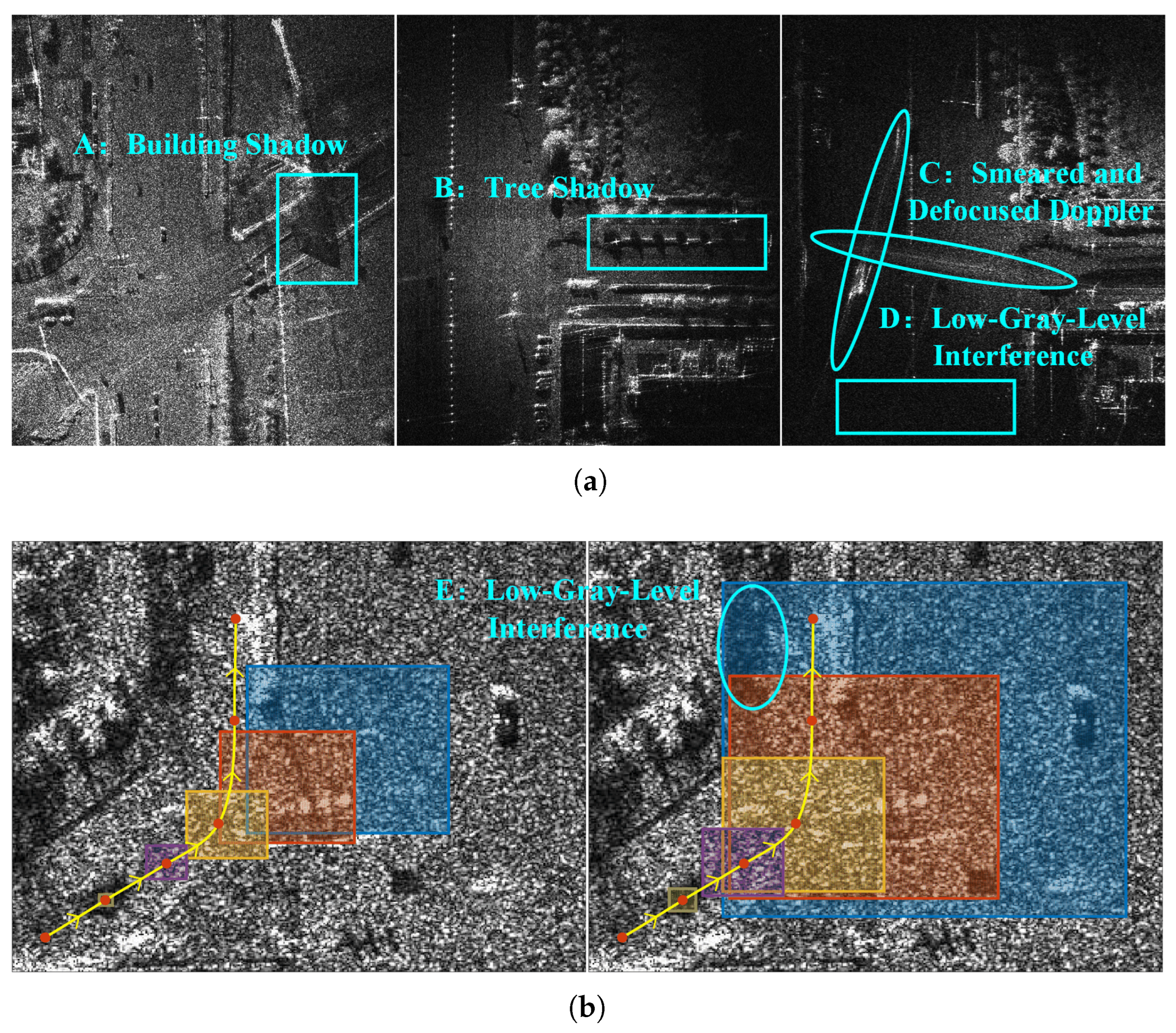
As low-gray-level regions in video SAR images, moving-target shadows are susceptible to interference from other common low-gray-level regions. Moreover, they exhibit simple appearance features due to shadow formation mechanisms. These factors bring great difficulties to robust shadow single-frame detection [18]. DP-TBD represents a classic multi-frame detection algorithm that can improve detection capability for dim shadows through multi-frame accumulation. In recent years, researchers have developed numerous advanced shadow detection algorithms based on the DP-TBD framework by leveraging the temporal motion characteristics of shadows in SAR images and even combining Doppler features from the corresponding RD spectra [12,14,26,27]. However, existing DP-TBD algorithms face performance limitations due to the constraints in platform number. Figure 1 illustrates the limitations of the single-platform shadow DP-TBD, where the used SAR images were generated by focusing measured data from UAV-borne video SARs using a time-domain imaging algorithm. The first subfigure in Figure 1a and the SAR images in Figure 1b were obtained from a W-band UAV-borne video SAR, while the second and third subfigures in Figure 1a were obtained from a terahertz-band UAV-borne video SAR.
The first challenge of single-platform shadow detection is the shadow occlusion effects caused by limited perspectives and interference from low-gray-level regions in SAR images. Video SAR typically monitors hotspot areas such as traffic intersections, roadways, and local battlefields. These areas often contain complex elevation structures and multiple targets with diverse motion states. Under specific observation geometries, stationary target shadows and Doppler features of other moving targets may create persistent occlusion in the regions of interest. As demonstrated in Figure 1a, typical examples include: building shadow in Region A, tree shadows along roads in Region B, and smeared and defocused Doppler features in Region C. Furthermore, the low-gray-level areas are common in SAR images, particularly at the illumination edges of radar beam, such as Region D. These phenomena make moving-target shadows either invisible or low-contrast, significantly degrading shadow-detection performance.
The second challenge arises from the multi-frame accumulation for maneuvering targets due to time-varying motion states. As shown in Figure 1b, assuming the DP-TBD algorithm requires accumulation of N = 6 frames to obtain the specified accumulation gain, where the yellow curves show the trajectory of a maneuvering target across N frames, red dots indicate its positions in each frame, and differently colored rectangular regions represent the state position distributions obtained through state temporal transitions in Equation (3). It can be seen that insufficient predicted states fail to cover the target’s trajectory while excessive states cause both high computational complexity and potential overlap to other low-gray-level regions (e.g., Region E), leading to inaccurate state estimation and error final decision. Therefore, the conventional DP-TBD algorithm struggles to detect maneuvering targets with long-term accumulation, while short-term accumulation cannot provide the necessary accumulation gain for reliable detection.

3. Dynamic Programming-Based Spatiotemporal Track-Before-Detect

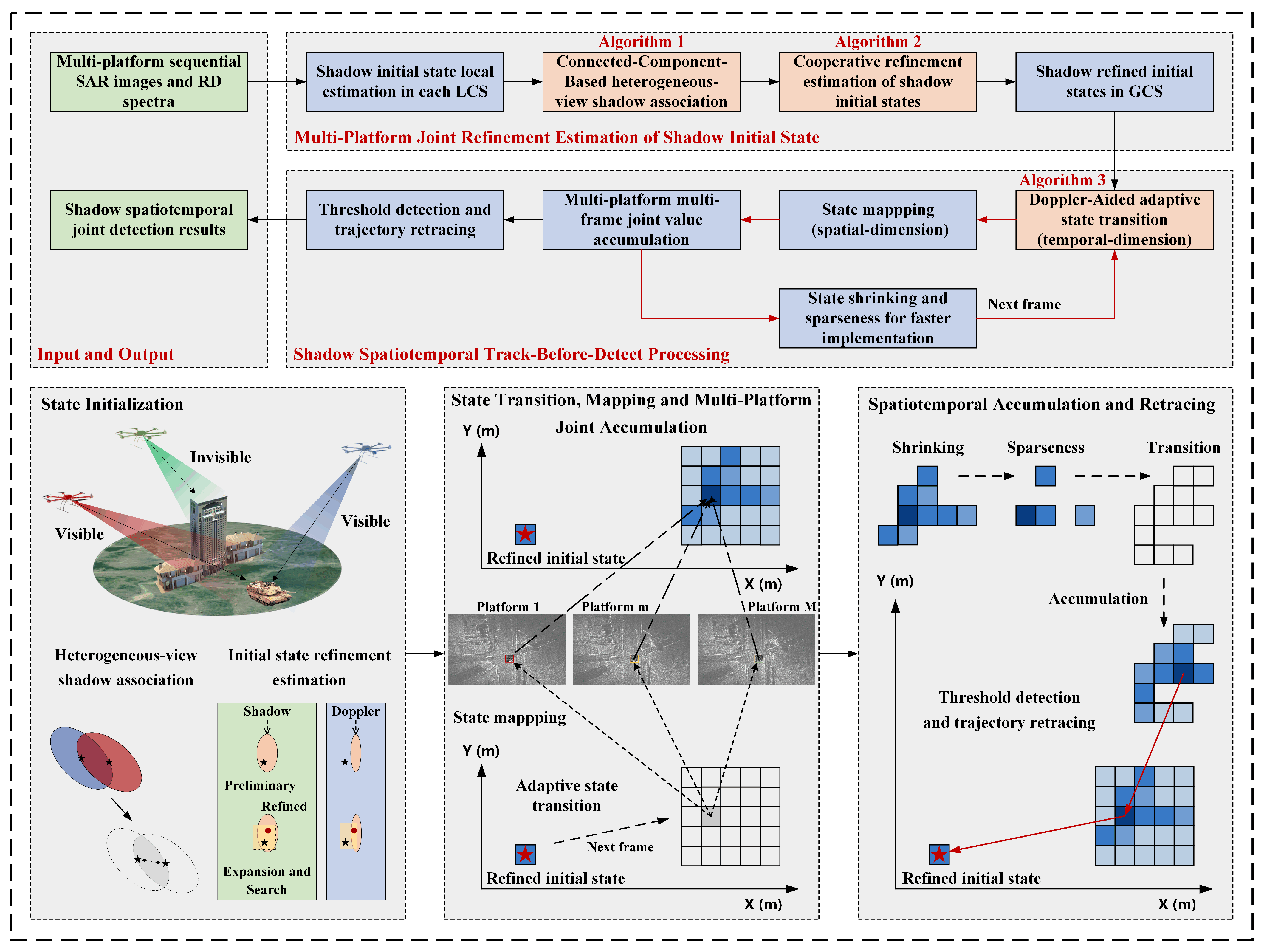
This paper proposes a DP-ST-TBD algorithm based on a distributed UAV-borne video SAR system to overcome both shadow occlusion and maneuvering target detection challenges in traditional single-platform DP-TBD processing. The detailed flowchart is illustrated in Figure 2.
Consider a distributed UAV-borne video SAR system comprising M platforms, where each platform employs frequency-division orthogonal signals to simultaneously observe the same area. The center frequency of the m-th video SAR is f m = f c + ( m 1 ) Δ f , while other system parameters are identical. Each platform independently focuses sequential SAR images using the back-projection-type (BP) time-domain imaging algorithm. Meanwhile, continuous pulses around the imaging aperture center are extracted to construct corresponding RD spectra [25]. For the m-th platform, the -th detection window and n-th high-resolution SAR image in Equation (1) can be, respectively, denoted as w l m and α n m . The corresponding RD spectrum of α n m is β n m , where stationary clutter is suppressed by adaptive moving target indication (MTI) filter. The j-th platform’s imaging coordinate system is set as the global coordinate system (GCS), i.e., α n = α n j . The state vector φ n k in Equation (2) represents the k-th candidate target’s global state in GCS, while φ n m k denotes its local state in the m-th local coordinate system (LCS).

3.1. Multi-Platform Joint Refinement Estimation of Shadow Initial State

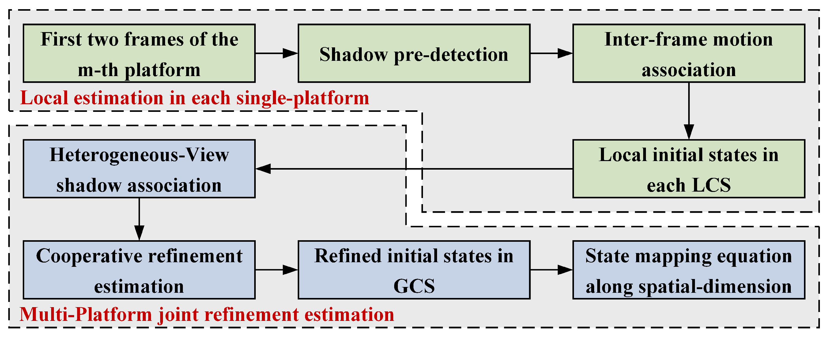
The computational load of the proposed DP-ST-TBD algorithm would be high if it directly operates on raw measurements. To address this, we propose a multi-platform joint refinement estimation method of shadow initial states, which can reduce the number of candidate targets in each detection window. As shown in Figure 3, this joint state initialization approach utilizes heterogeneous-view measurements to prevent failed initialization caused by invisible shadow in the single-view observation. Meanwhile, it incorporates heterogeneous-view Doppler features to correct image-domain state estimation errors, realizing globally refined initialization of shadow states and the suppression of certain false states.
Taking the joint refined estimation of shadow initial states in the -th detection window as an example, the first step is the local shadow state estimation in each platform’s LCS. For the m-th platform, the reference background I m is firstly extracted. Benefiting from high imaging frame-rate of video SAR and the used time-domain imaging algorithm, the geometric distortion between adjacent frames within the same detection window is slight, allowing the mean of all images in w l m to serve as the reference background. Subsequently, the backgrounds of the SAR images { α n m } n = 1 , 2 are removed to obtain residual images, { α ¯ n m } n = 1 , 2 , thereby minimizing interference from stationary targets and highlighting moving-target shadows. Then, a two-stage high false-alarm pre-detection process is used. The process is as follows: (1) preliminary detection using the fixed-threshold, morphological closing operation and connected component analysis, where the centroids of the detected, connected components are treated as preliminary shadow detection points; (2) high false-alarm detection using a two-dimensional constant false alarm rate (CFAR) detector centered at each preliminary detection point within the residual images, yielding potential shadow detection points for the first two frames. This two-stage pre-detection approach can effectively mitigate the computational burden compared with direct application of the two-dimensional CFAR detector to high-resolution SAR images.
Finally, the potential shadow detection points are matched by the inter-frame motion association while eliminating false detection points that violate kinematic constraints. Assume that ( x 1 m p , y 1 m p ) and ( x 2 m q , y 2 m q ) are detected points in the first and second frames, respectively. If the differential velocities satisfy Δ x [ x ˙ m i n , x ˙ m a x ] and Δ y [ y ˙ m i n , y ˙ m a x ] , the detected point ( x 1 m p , y 1 m p ) can be regarded as a candidate target and its local initial state can be expressed as
φ 1 m p = s 1 m p v 1 m p = x 1 m p y 1 m p Δ x Δ y T               Δ x = ( x 2 m q x 1 m p ) / Δ t , Δ y = ( y 2 m q y 1 m p ) / Δ t
The local initial state set C m = { φ 1 m p , Υ 1 m p } p = 1 P m in the m-th LCS can be obtained by traversing all detected points in the first frame and matching all detected points in the second frame, where Υ 1 m p is the set of all coordinate points in the connected component of state φ 1 m p and P m is the number of candidate targets.
The second step is the association of multi-platform local initial states in the GCS and the refinement estimation of global initial states using heterogeneous-view Doppler features. However, there are two key challenges in heterogeneous-view shadow association. The first challenge arises from the global deformation between heterogeneous-view SAR images, even when these images are focused by time-domain imaging algorithms on a unified imaging grid. This deformation primarily manifests as the rigid-body transformation, originating from platform-specific positioning errors during imaging that cause global offsets in heterogeneous-view SAR images. The second challenge arises from the observation-geometry-dependent nature of shadow projection, i.e., the shadow projection direction varies from observation perspectives. Consequently, even in registered SAR images, there are still positional differences in the shadows of the same moving target, leading to the deviations of shadow centers.
To solve the first challenge, common SAR image registration methods can be employed to correct the global deformation between heterogeneous-view SAR images. The rigid-body transformation between the GCS SAR image α n and the m-th LCS SAR image α n m can be expressed as
α n = H ( α n m )           x n y n = A m x n m y n m + B m
where m j , A m , and B m are the estimated rotation and translation parameters, respectively. ( x n , y n ) and ( x n m , y n m ) are coordinates in α n and α n m , respectively.
Based on Equation (7), the local initial state φ 1 m p and its connected component Υ 1 m p can be preliminary mapped to the GCS, which can be expressed as
                             φ ¯ 1 m p = s ¯ 1 m p v ¯ 1 m p = A m s 1 m p A m v 1 m p + B m 0 Υ ¯ 1 m p = A m Υ 1 m p + B m
where φ ¯ 1 m p is the rigid-body transformation of state φ 1 m p .
A moving target’s shadow comprises two components: (1) the ground projection of the target’s elevation structure, and (2) the background occlusion formed when the moving target blocks stationary scatterers along its trajectory during synthetic aperture time, which collectively constitute the complete moving-target shadow in video SAR imagery. In multi-platform heterogeneous-view cooperative detection, the former’s spatial distribution strongly depends on each platform’s observation geometry. Therefore, in registered heterogeneous-view SAR images, elevation projection differences cause shadow center deviation for the same target, yet shared background occlusions maintain overlapping shadow regions across perspectives. A connected-component-based heterogeneous-view shadow association approach is proposed in Algorithm 1, where operator ← represents the operation of adding an element to the set. Therefore, a global preliminary initial state set C ̀ = { φ ̀ 1 p } p = 1 P and corresponding label set D ̀ = { ι ̀ p } p = 1 P are obtained, where ι ̀ p denotes the originating platforms for state φ ̀ 1 p .
Algorithm 1 proposes a novel association method based on the intrinsic characteristics of heterogeneous-view shadows. It utilizes the background occlusion part of the shadow. This part exhibits overlap in the heterogeneous-view SAR images of the same target, providing a stable and observation-perspective-invariant physical basis for association. It addresses the heterogeneous-view shadow association problem by using shared physical overlapping regions across different perspectives.
Algorithm 1 Connected-component-based heterogeneous-view shadow association
Input: multi-platform local initial state set C = { C m } , m = 1 , , M .
Output: global preliminary initial state set C ̀ and label set D ̀ .
  1:  Initialization: cluster set ε = { C j } = { ε 1 , , ε P j } , ε p = { φ 1 j p , Υ 1 j p } , D ̀ = { ι ̀ p } p = 1 P j , ι ̀ p = { j } .
  2:  for m = 1 to M ( m j ) do
  3:        Transform C m to the GCS using Equation (8).
  4:        for  p = 1 to P m  do
  5:              Calculate the intersections between Υ ¯ 1 m p and all connected components in ε .
  6:              if q-th intersection exceeds the preset threshold V a  then  ε q { φ ¯ 1 m p , Υ ¯ 1 m p } , ι ̀ q m.
  7:              else if none of intersections exceed V a  then new subset: ε { φ ¯ 1 m p , Υ ¯ 1 m p } , D ̀ m.
  8:              end if
  9:        end for
10:  end for
11:   C ̀ is obtained by calculating the mean state of each subset in ε .
In the pre-detection stage of each platform, the positions of moving-target shadows are typically selected as the centroids of connected components. Due to the difficulty in extracting complete shadows from SAR images, the localized shadow positions inherently contain errors. These errors propagate into the velocity components of the initial states through Equation (6), which adversely affects target’s multi-frame search and detection. In our previous work, we addressed the problem of inaccurate shadow states in conventional DP-TBD algorithms by correcting state errors using moving targets’ Doppler features [27]. However, constrained by single-platform observation geometry, relying solely on single-platform Doppler features for initial state’s refinement estimation may lead to failed initialization, particularly for targets with low radial velocities whose Doppler features fall into the main clutter region. Therefore, this paper extends the initial state refinement estimation method proposed in [27] by incorporating heterogeneous-view Doppler features for state error correction. The procedure is detailed in Algorithm 2, yielding a global refined initial state set C ˜ = { φ ˜ 1 k } k = 1 K and a filtered label set D ˜ = { ι ˜ k } k = 1 K .
Algorithm 2 Cooperative refinement estimation of shadow initial state
Input: global preliminary initial state set C ̀ and label set D ̀ .
Output: global refined initial state set C ˜ and filtered label set D ˜ .
  1:  for p = 1 to P do
  2:        Initialization: state set ψ = .
  3:        for  m = 1 to M do
  4:              Inversely transform φ ̀ 1 p to the m-th LCS using Equation (8).
  5:              Local state is randomly expanded and the expanded state set is mapped to the RD spectrum β 1 m [27].
  6:              A 2D CFAR detector centered on each expanded state is used to search for potential moving targets.
  7:              if i-th local expanded state covers the moving target then ψ i-th expanded state in the GCS and continues to the next iteration.
  8:              end if
  9:        end for
10:        if the number of states contained in ψ exceeds the threshold V r ( 1 V r M ) then refined initial state φ ˜ 1 k is obtained by calculating the mean state of ψ and label ι ˜ k = ι ̀ p .
11:        end if
12:  end for
Algorithm 2 extends the previous single-platform correction method [27] by using heterogeneous-view Doppler features from multiple platforms for state error correction. This approach effectively avoids initialization failures caused by targets having excessively low radial velocity (where Doppler falls into the main clutter region). It enhances the robustness of initialization through cooperative correction.
Furthermore, the state’s spatial mapping equation can be derived based on the relationship between the local initial state and global refined state. For the k-th target, given its global refined state φ ˜ 1 k and local initial state φ 1 m k , the shadow center deviation and velocity deviation can be expressed as
Δ s m k = s ˜ 1 k s ¯ 1 m k = x ˜ 1 k x ¯ 1 m k y ˜ 1 k y ¯ 1 m k T Δ v m k = v ˜ 1 k v ¯ 1 m k = Δ x ˜ 1 k Δ x ¯ 1 m k Δ y ˜ 1 k Δ y ¯ 1 m k T
Therefore, the spatial mapping of the k-th target’s state from the m-th LCS to the GCS in Equation (8) can be modified as
φ ˜ 1 k = G m k ( φ 1 m k ) = A m s 1 m k A m v 1 m k + B m 0 + Δ s m k Δ v m k
Algorithms 1 and 2 improve the estimation accuracy and robustness of the initial state by utilizing the multi-platform heterogeneous-view measurements.

3.2. Multi-Platform, Multi-Frame Joint Accumulation Based on Adaptive State Transition

Starting from each state in the global refined initial state set C ˜ , the value functions of moving targets are dynamically accumulated along both temporal and spatial dimensions. As shown in Equation (3) and Figure 1, the state temporal dimension transition relies on quantized acceleration process noise for target search, where the selection of δ x and δ y significantly impacts detection performance. Particularly in multi-frame detection of maneuvering targets, it is challenging to adaptively determine the number of predicted states per frame, which may result in either insufficient or redundant states for effective search.
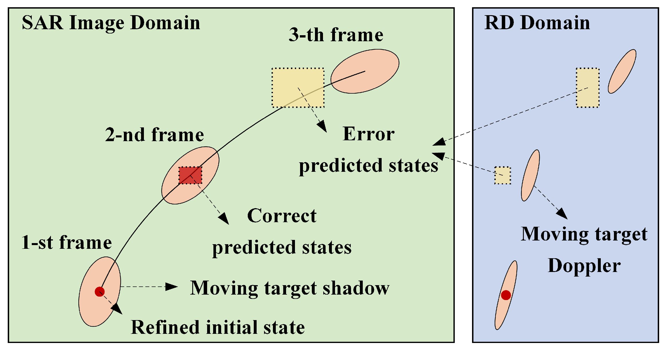
The root cause of the aforementioned issues lies in the difficulty of effectively constraining the velocity components in predicted states during temporal dimension transitions when relying solely on image-domain shadows, which are insensitive to target velocity. As illustrated in Figure 4, even if the predicted states can cover the shadow in the second frame, their velocities may deviate from the true target velocity, leading to failed search in the third frame. Although increasing process noise can ensure successful search, it inevitably results in redundant predicted states in later stages. It should be noticed that Doppler features exhibit higher sensitivity to velocity variations particularly under multi-platform cooperative observation, where heterogeneous-view Doppler features can better capture true target motion dynamics. Therefore, a Doppler-aided adaptive state transition method is proposed, which utilizes the heterogeneous-view Doppler features to guide the selection of acceleration process noise, thereby ensuring predicted states precisely cover the target’s velocity at each frame.
In the proposed adaptive state transition, the acceleration process noise sequence in Equation (3) can be expressed as
ς n = h n 1 2 , , 0 , , h n 1 2 , U 1 h n 2 2 , , 0 , , h n 2 , U 0
where h n is the number of ς n . U 1 indicates h n is an odd number while U 0 indicates h n is an even number. The adaptive state transition method is detailed in Algorithm 3.
Algorithm 3 Doppler-aided adaptive state transition
Input: predicted state set Ω n 1 k .
Output: predicted state set Ω n k .
  1:  Initialization: h n = 3 , ρ = 1 , the maximum number H and threshold V r [ 1 , M ] .
  2:  while h n < = H and ρ = 1  do
  3:        Initialization: u = 0 .
  4:        Temporal dimension transition using Equations (3) and (11): Ω n 1 k Ω n k .
  5:        for  m = 1 to M do
  6:              Transform Ω n k inversely to the m-th LCS using Equation (10).
  7:              Map local states to the RD spectrum β n m [27].
  8:              Calculate the local states’ range and Doppler coordinate intervals [ r m i n , r m a x ] and [ d m i n , d m a x ] .
  9:              Denote the 2D region formed by these coordinates as Π .
10:              Search potential moving targets in Π using the two-stage detection (fixed-threshold and 2D CFAR detector) followed by morphological processing.
11:              if detection point exists within Π then u = u + 1 and continues to the next iteration.
12:              end if
13:        end for
14:         Ω n k can cover the Doppler component of the moving target in the u platforms.
15:        if  u < V r then h n = h n + 1 .
16:        else  ρ = 0 .
17:        end if
18:  end while
Although adaptive state transition can theoretically be achieved using single-platform RD spectrum, the detection of moving target’s Doppler is significantly influenced by observation geometry, leading to unfavorable situations where targets may have low radial velocities or low RCS. Therefore, Algorithm 3 can enhance the robustness of the adaptive state transition by utilizing heterogeneous-view Doppler features.
Algorithm 3 uses heterogeneous-view Doppler features as feedback signals to dynamically guide the selection of acceleration process noise, which optimizes the search strategy of traditional DP-TBD and adaptively controls the state transition range. It balances computational efficiency while ensuring that the predicted states accurately cover the real target in both position and velocity components.
After obtaining Ω n k , the value accumulation of the moving-target shadow in Equation (4) can be reformulated as
Θ ( φ n k ) = max φ n 1 k τ ( φ n k ) Θ ( φ n 1 k ) + m w m ν ( φ n m k )
where φ n k Ω n k , m ι ˜ k , w m is the normalized weight. If ι ˜ k contains M k platforms, then w m = 1 / M k . φ n m k is the local state in the m-th LCS which can be obtained by inverse transformation of φ n k based on Equation (10).
In Equation (12), the platforms eligible to participate in the spatiotemporal accumulation for the k-th target are determined by the target’s label obtained by Algorithm 2. Taking two-platform cooperative detection as an example, if the initial state of the k-th target is contributed by both platforms, then its subsequent values are accumulated jointly. However, if the k-th target fails to be correctly initialized by one of the platforms, which means the shadow is contaminated by clutter; thus, it should automatically revert to single-platform accumulation to ensure accumulated value’s correctness.

3.3. Analysis of Spatiotemporal Joint Accumulation

Although Algorithm 3 meets the needs of maneuvering target search with as small a state space as possible, it still faces two challenges. First, the dense state distribution leads to high computational complexity. As shown in Figure 1, the predicted states exhibit a regular and dense rectangular distribution, containing a large number of invalid states. It can be considered that these states do not contribute to the final detection since their accumulated values have deviated from the correct cumulative distribution. Therefore, it is necessary to eliminate invalid states to reduce the computational complexity of adaptive state transitions. Second, the number of accumulated platforms varies across different targets due to the influence of initialization. To achieve consistent detection performance, the number of accumulated frames should be adjusted accordingly for different targets. To solve these two challenges, we analyze the detection threshold and advantages of spatiotemporal joint accumulation using typical road clutter and target distribution models.
Assume that the detection threshold after m-platform n-frame accumulation is V n m , the probability of detection P d and the probability of false alarm P f a can be expressed as
P f a = V n m + F n m Θ ( ν , n , m ) | H 0 d ν = 1 F n m ( V n m | H 0 ) P d = V n m + F n m Θ ( ν , n , m ) | H 1 d ν = 1 F n m ( V n m | H 1 )
where H 0 means target-absent while H 1 means target-present. Θ ( ν , n , m ) = i = 1 n j = 1 m ν i j is the accumulated value. F n m is the probability density function (PDF). F n m is the corresponding cumulative density function (CDF).
Different distributions of road clutter or moving-target shadow in the video SAR images are considered. The detection threshold V n m can be obtained under the constant false alarm probability, detailed as follows.

3.3.1. Gaussian Distribution

Assuming that both road clutter and moving-target shadows follow independent Gaussian distributions along the temporal and spatial dimensions. In the n-th frame SAR image of the m-th platform, the clutter and shadows are distributed as X c n m N ( μ c n m , σ c n m 2 ) and X t n m N ( μ t n m , σ t n m 2 ) , where μ c n m and σ c n m represent the mean and standard deviation of the clutter distribution. After M-platform N-frame joint accumulation, the joint clutter distribution can be expressed as
X c N M N ( μ c N M , σ c N M 2 ) μ c N M = n = 1 N m = 1 M w m μ c n m σ c N M 2 = n = 1 N m = 1 M w m 2 σ c n m 2
Let the false alarm probability set for shadow detection be P f a = η . By transforming Equation (14) into a standard Gaussian distribution, the detection threshold V N M can be expressed as
V N M = μ c N M + σ c N M ϑ 0
where ϑ 0 makes the CDF of standard Gaussian distribution equals to 1 η .
Equation (15) represents the general expression for the detection threshold V N M under independent Gaussian distributions. If we further assume that the road clutter in the same region satisfies the independent and identically distributed (i.i.d.) condition along the temporal dimension (different frames from the same platform) while exhibiting proportional relationships along the spatial dimension (different platforms), i.e., μ c n m = d c m μ c and σ c n m = d c m σ c with normalized weights w m = 1 / M , then Equation (15) can be expressed as
V N M = N D c 1 μ c + N D c 2 σ c ϑ 0 M
where D c 1 = m = 1 M d c m , D c 2 = m = 1 M d c m 2 and d c m > 0 is the scale factor for the road clutter distribution.
Building upon Equation (16), we can analyze the relationship between the number of frames and platforms required to achieve identical detection performance in multi-platform, multi-frame joint accumulation. Under a constant false alarm probability η , assuming that single-platform N-frame accumulation can achieve a detection probability of ξ , which can be expressed as
ρ 0 = V N 1 μ t N 1 σ t N 1
where ρ 0 makes the CDF of standard Gaussian distribution equals to 1 ξ , μ t N 1 and σ t N 1 represent the mean and standard deviation of the moving-target shadow distribution after N-frame accumulation in a single platform, respectively. Under the same assumptions, we have μ t N 1 = N μ t and σ t N 1 = N σ t . Therefore, Equation (17) can be simplified to
ρ 0 = N ( μ c μ t ) + N σ c ϑ 0 N σ t
Assuming that M-platform G-frame accumulation can also achieve the same detection probability ξ ; thus, we have
ρ 0 = V G M μ t G M σ t G M = G ( D c 1 μ c D t 1 μ t ) + G D c 2 σ c ϑ 0 G D t 2 σ t
where D t 1 = m = 1 M d t m , D t 2 = m = 1 M d t m 2 , and d t m > 0 is the scale factor for the moving-target shadow distribution.
Combining Equation (18) with Equation (19), when d c m = d t m = 1 , i.e., both the road clutter and moving-target shadows satisfy the i.i.d. condition across different platforms, we can obtain
G = N M
The above analysis demonstrates that, under the i.i.d. condition, the required number of frames and platforms for spatiotemporal joint accumulation exhibit an inverse proportion relationship to achieve theoretically equivalent detection performance. Even when the i.i.d. condition is not satisfied, a negative correlation also persists. Therefore, incorporating spatial dimension multi-platform accumulation can reduce the temporal dimension frame requirements for DP-TBD algorithms to achieve reliable detection. This advantage is helpful for maneuvering target detection, which can avoid the long-term accumulation issues discussed in Section 2.3.

3.3.2. Gamma Distribution

Assuming that both road clutter and moving-target shadows follow independent and identically Gamma distributions along the temporal and spatial dimensions. In the n-th frame SAR image of the m-th platform, the clutter and shadows are distributed as X c n m G ( γ c , λ c ) and X t n m G ( γ t , λ t ) , where γ c and λ c represent the shape and scale parameters of the clutter distribution. After M-platform N-frame joint accumulation, the joint clutter distribution can be expressed as
X c N M G ( γ ^ c , λ ^ c )
where γ ^ c = N M γ c and λ ^ c = λ c / M .
Similarly, let the false alarm probability equal to η . By substituting the PDF given in Equation (21) into Equation (13), we have
η = V N M + λ ^ c γ ^ c Γ ( γ ^ c ) ν γ ^ c 1 e x p ( λ ^ c ν ) d ν = λ c M Γ ( N M γ c ) V N M + λ c ν M N M γ c 1 e x p λ c ν M d ν
where Γ ( · ) is the Gamma function. Let t = λ c ν / M , Equation (22) can be simplified to
η = 1 Γ ( N M γ c ) λ c V N M / M + t N M γ c 1 e x p ( t ) d t = Γ ( N M γ c , λ c V N M / M ) / Γ ( N M γ c )
Therefore, the detection threshold V N M can be numerically solved based on Gamma function.

3.4. State Shrinking and Sparseness for Faster Implementation

Based on the multi-platform, multi-frame detection thresholds, this paper employs shrinking and sparseness strategies to screen the predicted states, which can reduce the computational load caused by dense states in the spatiotemporal dual-dimensional search.
Assuming the k-th target is jointly accumulated and detected by M k platforms. First, detection thresholds are used to evaluate whether states contribute to moving-target shadow detection. In the early stages of the DP processing, the number of predicted states is usually small and premature shrinking of these states may hinder effective target search. Therefore, the shrinking and sparseness of predicted states begin before the state transition from the ( ϕ 1 )-th frame to the ϕ -th frame, where ϕ satisfies 2 < ϕ N k and N k is the number of accumulated frames. According to the relationship between the number of accumulated frames and platforms analyzed in Section 3.3, it should satisfy N / M k N k < N . The preliminary screening of predicted states can be expressed as
Θ ( φ ϕ 1 k ) Z 0 Z 1 V ( ϕ 1 ) M k
where φ ϕ 1 k Ω ϕ 1 k , Ω ϕ 1 k is obtained by Algorithm 3. During the state screening stage, a higher false alarm probability compared to the final decision can be set to obtain V ( ϕ 1 ) M k based on the analyses in Section 3.3.
Equation (24) determines whether a state is valid by comparing its accumulated value with the threshold. The state φ ϕ 1 k will be retained if it satisfies condition Z 1 . Conversely, if it meets condition Z 0 and its neighborhood in the RD domain does not contain the detection points of the potential moving targets identified in Algorithm 3, then this state is considered invalid and will be eliminated to prevent its transition to the ϕ -th frame. After removing all invalid states, the set of transferable states Ω ¯ ϕ 1 k is significantly reduced, decreasing the computational load of the proposed algorithm.
However, there are still many redundant states in Ω ¯ ϕ 1 k since the moving-target shadow usually occupies several resolution cells in the high resolution SAR image. Though these redundant states have correct accumulated values, they are dense and may be transferred to the same spatial position in the next frame, especially for spatially adjacent states. Theoretically, sparse states can be used to search for the large-scale target. Therefore, the sparseness strategy is proposed, where sparse states can be obtained through downsampling the state space. It ensures that the coverage of Ω ¯ ϕ 1 k remains almost unchanged while reducing the number of states. Furthermore, the row and column indices corresponding to the maximum accumulated value are retained to ensure this key state is not deleted. The set of all states after shrinking and sparseness is denoted as Ω ^ ϕ 1 k which presents sparse distribution.
The computational load of the proposed DP-ST-TBD algorithm is significantly reduced by using the shrinking–sparseness strategy which only retain a few sparse states. The final valid states in Ω ^ ϕ 1 k are transferred to the next discrete time to integrate the value. After multi-platform, multi-frame joint accumulation, the decision for the k-th target in the proposed DP-ST-TBD algorithm can be expressed as
φ ^ N k k = arg max φ N k k Ω N k k Θ ( φ N k k ) s . t . Θ ( φ ^ N k k ) > V N k M k
The declared target trajectory Φ k = { φ ^ 1 k , , φ ^ N k k } can be obtained by exploiting the retracing function. Algorithm 4 gives detailed procedures of the proposed DP-ST-TBD algorithm in the -th detection window. After detection, multiple short trajectories are generated, and they are either merged into the previous trajectories of the same targets to generate the long trajectories or are considered as newborn trajectories.
Algorithm 4 The proposed DP-ST-TBD algorithm
Input: SAR images α n m and RD spectra β n m , n = 1 , , N , m = 1 , , M .
Output: Declared target trajectories.
  1:  Single-Platform local estimation → shadow local initial state set C m .
  2:  Heterogeneous-view shadow association based on Algorithm 1→ global preliminary initial state set C ̀ .
  3:  Refinement estimation based on Algorithm 2→ global refined initial state set C ˜ = { φ ˜ 1 k } k = 1 K .
  4:  for k = 1 to K do
  5:        At discrete time n = 1 : initialization Θ ( φ ˜ 1 k ) = ν ( φ ˜ 1 k ) .
  6:        Determine the number of accumulated platforms M k and frames N k .
  7:        for  n = 2 to N k  do
  8:              if  n [ ϕ , N k ]  then
  9:                    Temporal dimension adaptive state transition based on Algorithm 3: Ω n 1 k Ω n k .
10:              else
11:                    State shrinking–sparseness and adaptive state transition: Ω n 1 k Ω ¯ n 1 k Ω ^ n 1 k Ω n k .
12:              end if
13:              Spatial dimension state mapping using Equation (10): Ω n k Ω n m k .
14:              Spatiotemporal joint accumulation using Equation (12).
15:        end for
16:        Detection using Equation (25).
17:        if Equation (25) is satisfied then
18:              Obtain declared state φ ^ N k k and retrace trajectory Φ k .
19:        end if
20:  end for

4. Experiments

4.1. Introduction to Experimental Data

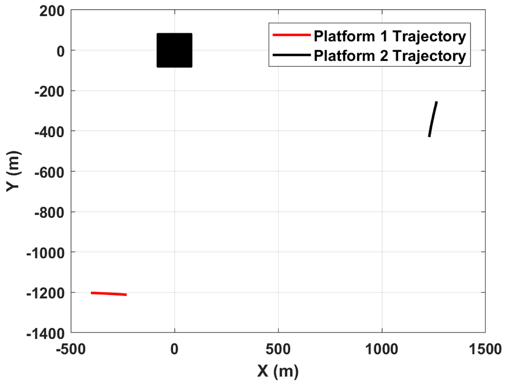
The validation is conducted using dual-pass measured data of the same area collected by a UAV-borne terahertz-band video SAR at different perspectives. The dual-pass measured data exhibit heterogeneous squint angles and different clutter responses; thus, they are treated as echoes of a distributed UAV-borne video SAR system with two platforms. The imaging geometry is illustrated in Figure 5, where two platforms fly at an altitude of 800 m and use time-domain algorithms to image a scene of 80 m × 80 m with a resolution of 0.15 m.
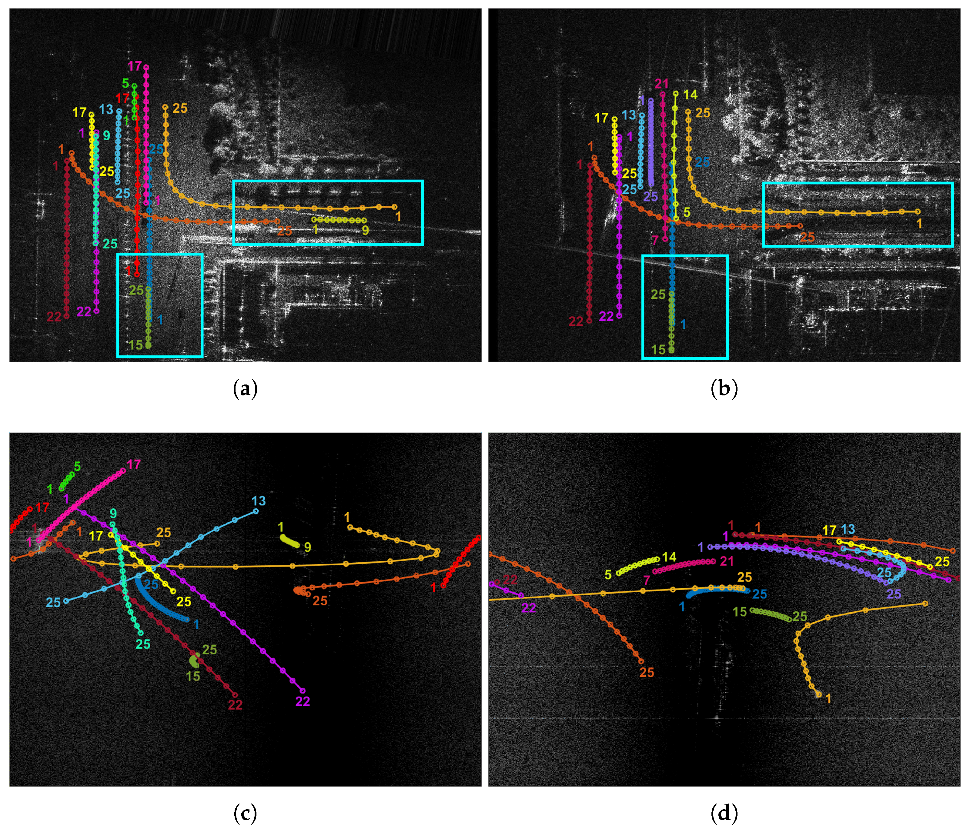
To validate the proposed cooperative detection method, eight moving targets with different sizes and motion states are injected into the measured echoes of the two heterogeneous-view video SARs. The moving-target shadows are simulated following the method described in [25], which involves canceling the background echoes in their respective regions. Through non-overlapping aperture processing and the BP-type imaging algorithm, each of the two platforms generated 25 frames of SAR images. This process produced a total of 304 simulated moving-target shadows. Meanwhile, in each imaging aperture, 1024 consecutive pulses around the aperture center are selected to generate corresponding RD spectra, while adaptive MTI techniques are applied to suppress main clutter. It should be noted that since the equivalent echoes were actually acquired in separate time slots, the measured moving targets appear at different times. Specifically, Platform 1 contains 5 measured moving targets and Platform 2 contains 3. These measured moving targets generated 65 and 50 measured shadows in the SAR images of the two heterogeneous-view platforms, respectively. In our experiments, these measured moving targets are considered as the special case observable by only one video SAR, i.e., single-view case. Therefore, all simulated and measured targets collectively produce a total of 419 shadows across the 25-frame SAR images, providing a solid data foundation for algorithm validation.
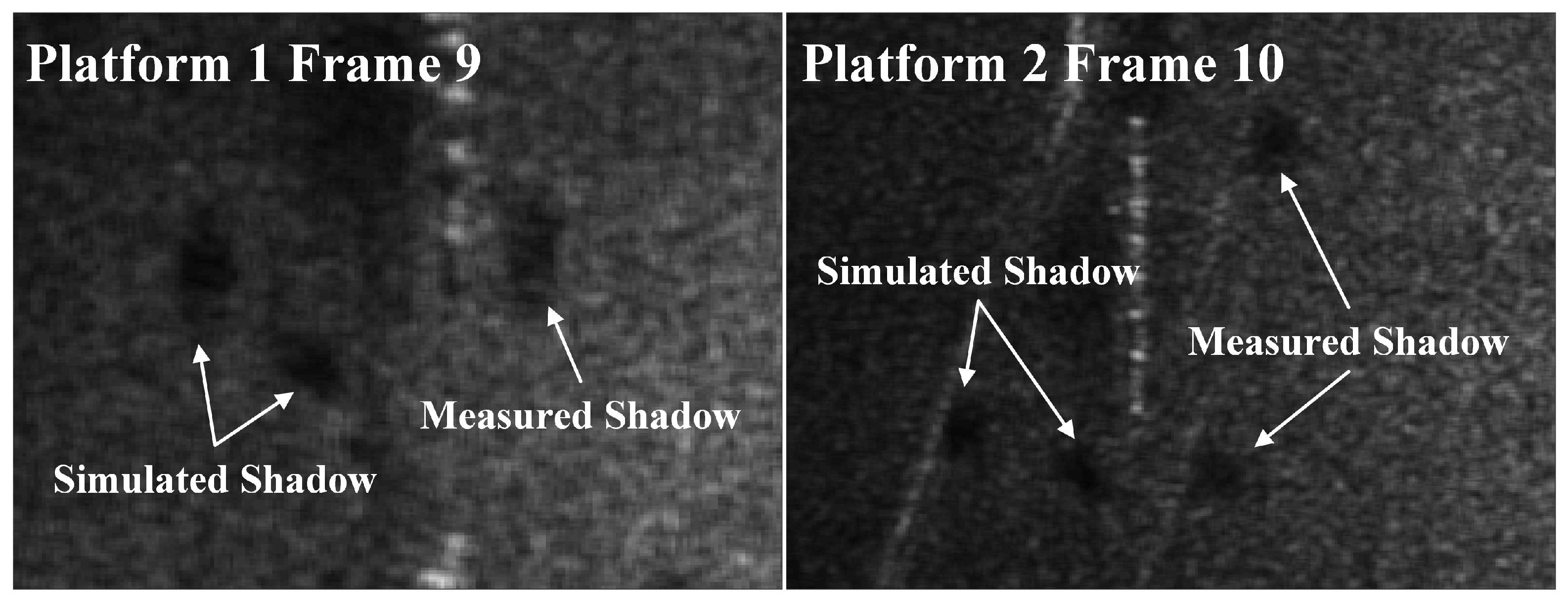
Figure 6 presents the experimental data using the first frame as an example. The cyan rectangles highlight regions with significant differences in heterogeneous-view SAR images, primarily manifested in three aspects: (1) the shadow projection directions of stationary targets (e.g., roadside trees) exhibit distinct variations; (2) the road clutter power shows noticeable changes due to RCS differences under different perspectives; (3) the heterogeneous-view SAR images demonstrate global deformations and illumination area variations affected by platform positioning errors and beam pointing inaccuracies, such as different echo power at image edges. These differences may cause moving-target shadows to become invisible in certain perspectives. Moreover, Figure 6 displays both simulated and measured moving-target shadows and Doppler trajectories in 25 frames, including their initiation and termination frame indices. In Figure 6, identical colors represent the same targets. It can be seen that the targets to be detected exhibit complex and diverse motion states, and each target demonstrates different Doppler shifts under different perspectives. Moreover, Figure 7 compares the morphology of simulated and measured shadows in specific frames. Our simulation process accounts for a range of sizes and motion states comparable to those of the measured targets; therefore, the simulated shadows are highly similar to the measured ones.

4.2. Verification of Spatiotemporal Joint Detection Performance

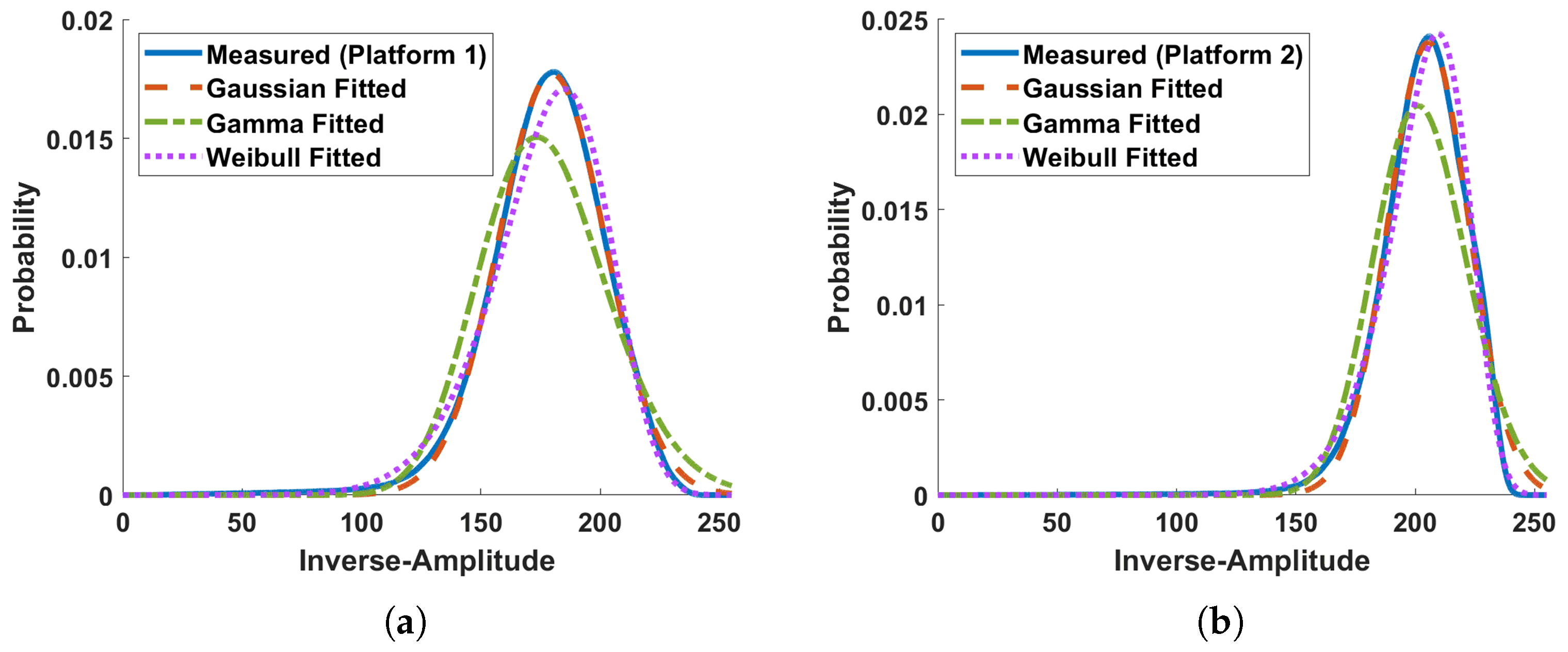
First, simulation experiments are conducted to validate the detection thresholds analyzed in Section 3.3 and the advantages of multi-platform, multi-frame joint accumulation. Statistical analyses of road clutter in the heterogeneous-view SAR images are performed to obtain the measured inverse-amplitude PDFs. Subsequently, we perform fitting using Gaussian, Gamma, and Weibull distributions, respectively. Figure 8a,b show the measured and three fitted PDFs for Platform 1 and Platform 2, respectively. Table 1 provides the RMSE between the fitted PDFs and measured PDFs. The statistical results of measured data demonstrate that the Gaussian distribution more accurately characterizes the road clutter distribution in the used video SAR images.
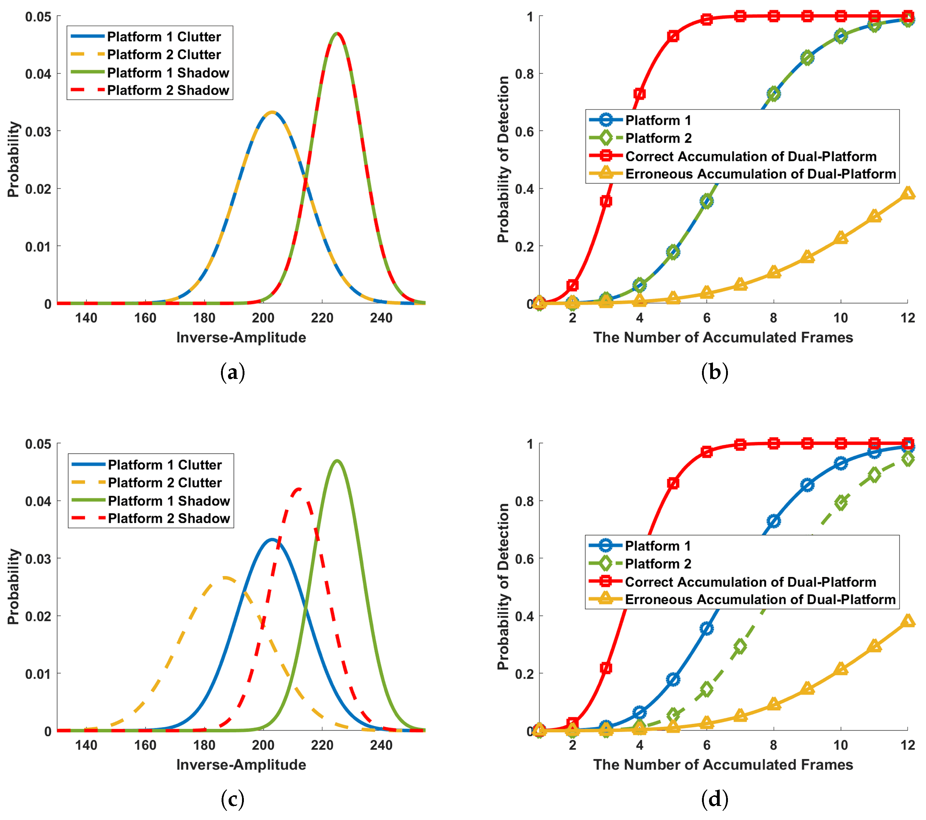
The multi-platform, multi-frame joint accumulation performances of the proposed DP-ST-TBD algorithm under Gaussian distribution assumptions are analyzed in Figure 9. Figure 9a shows the PDFs when both the road clutter and shadows follow the i.i.d. condition along temporal dimension (different frames within one platform) and spatial dimension (different platforms). Under this assumption, we compute detection thresholds for different frames and derive the detection probability P d under various accumulation conditions. Figure 9b shows detection performance curves with P f a = 10 6 , where the red curve represents correct multi-platform accumulation, i.e., accumulating shadows from both platforms according to Equation (12). Results demonstrate an inverse proportion relationship between the number of required frames and platforms. For example, four-frame dual-platform accumulation achieves equivalent P d to eight-frame single-platform accumulation. Furthermore, Figure 9c shows PDFs when the two platforms follow different Gaussian distributions, and Figure 9d compares detection performance under temporally i.i.d. but spatially independent non-identically distribution conditions. It can be seen that, even without spatial i.i.d. condition, a negative correlation persists between the number of required frames and platforms. This experiment proves the proposed DP-ST-TBD algorithm’s spatial multi-platform accumulation can effectively reduce temporal frame-number requirements compared to the conventional single-platform DP-TBD algorithm. Moreover, the yellow curves in Figure 9b,d represent erroneous accumulation cases, i.e., accumulating Platform 1’s clutter with Platform 2’s shadows, demonstrating performance degradation. Therefore, the weighting factor w m in Equation (12) is introduced to mitigate the adverse impact of clutter components at locations where shadows become invisible in certain platforms on the spatiotemporal accumulation performance.

4.3. Results of the Proposed DP-ST-TBD Algorithm

The moving-target shadow cooperative detection is conducted based on 25-frame SAR images and corresponding RD spectra of two video SARs with different perspectives. To ensure the fairness of the comparative experiments, two-stage cooperative detection approaches are adopted as the compared methods. First, conventional single-platform shadow DP-TBD approaches including multi-frame TBD (e.g., sliding-window-based (SW) DP-TBD) and multi-frame multi-domain TBD (e.g., Dual-DP-TBD [27]) are independently applied to the measurements from Platform 1 and Platform 2 for shadow detection, yielding moving-target shadow tracks in their respective LCSs. Subsequently, the track-level nearest-neighbor association and fusion (TAF) of the two-platform tracks are performed in the GCS, thereby obtaining track-level fused detection results. The two compared methods are denoted as SW-DP-TBD+TAF and Dual-DP-TBD+TAF, respectively. In terms of parameter settings, the proposed DP-ST-TBD algorithm employs a detection window length of N k = 9 and window step size of S = 4 . In each detection window, the number of accumulated frames is reduced to N k = 5 if the number of accumulated platforms of the k-th target is M k = 2 . The maximum number of the acceleration process noise is set to H = 9 in the adaptive state transition, while h n = 9 is fixed in SW-DP-TBD.
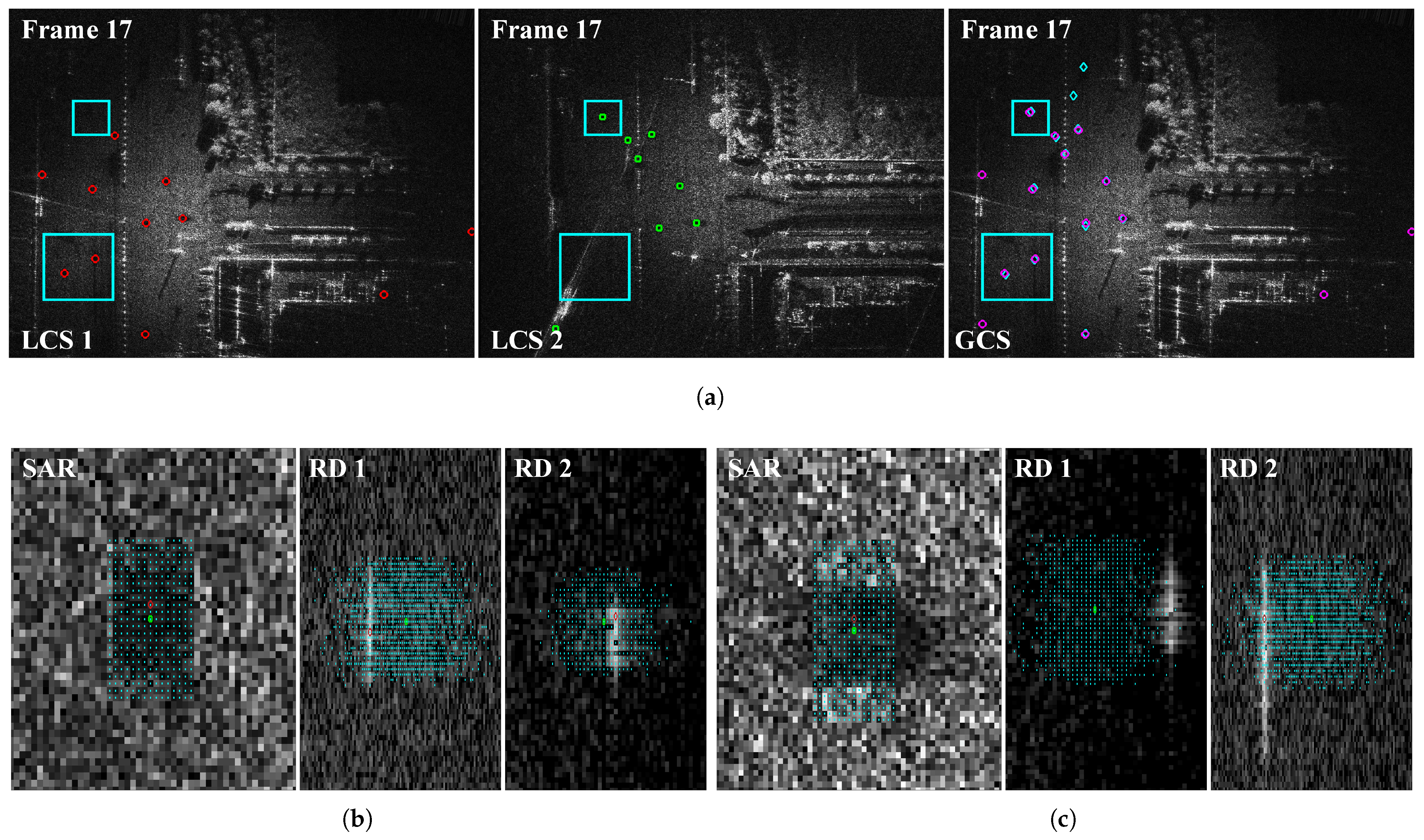
Figure 10 shows the multi-platform joint refinement estimation results of shadow initial states in the fifth detection window, using the 17th frame as an example. First, local estimation of potential shadow states is performed in each platform’s LCS. The first two subfigures in Figure 10a show the local initial states after shadow pre-detection and inter-frame motion association in both LCSs, where cyan rectangles mark cases of single-platform initialization failures. Due to beam pointing errors between the two video SARs, significant contrast differences exist for the same moving target at image edges under different perspectives, leading to initialization failures in certain perspectives. In experiments, Platform 1’s LCS is treated as the GCS. The third subfigure in Figure 10a displays heterogeneous-view association results in the GCS, where purple circles represent global preliminary initial states obtained by Algorithm 1 and cyan diamonds indicate the shadow ground-truths. The results demonstrate that heterogeneous-view observation can avoid some cases of single-view initialization failures. Although preliminary estimation inevitably contains some false states, they can be suppressed through subsequent refinement estimation and joint detection. Finally, refinement estimation of shadow initial states is performed by jointly utilizing multi-platform heterogeneous-view RD spectra, as detailed in Algorithm 2 with threshold V r = 1 . Figure 10b,c show the results of two typical targets, where cyan points indicate expanded states in GCS SAR images and multi-platform RD spectra, green and red circles represent global preliminary and refined initial states, respectively. The results confirm that the proposed refinement estimation method can effectively correct estimation errors (particularly velocity errors) introduced in the state local estimation.
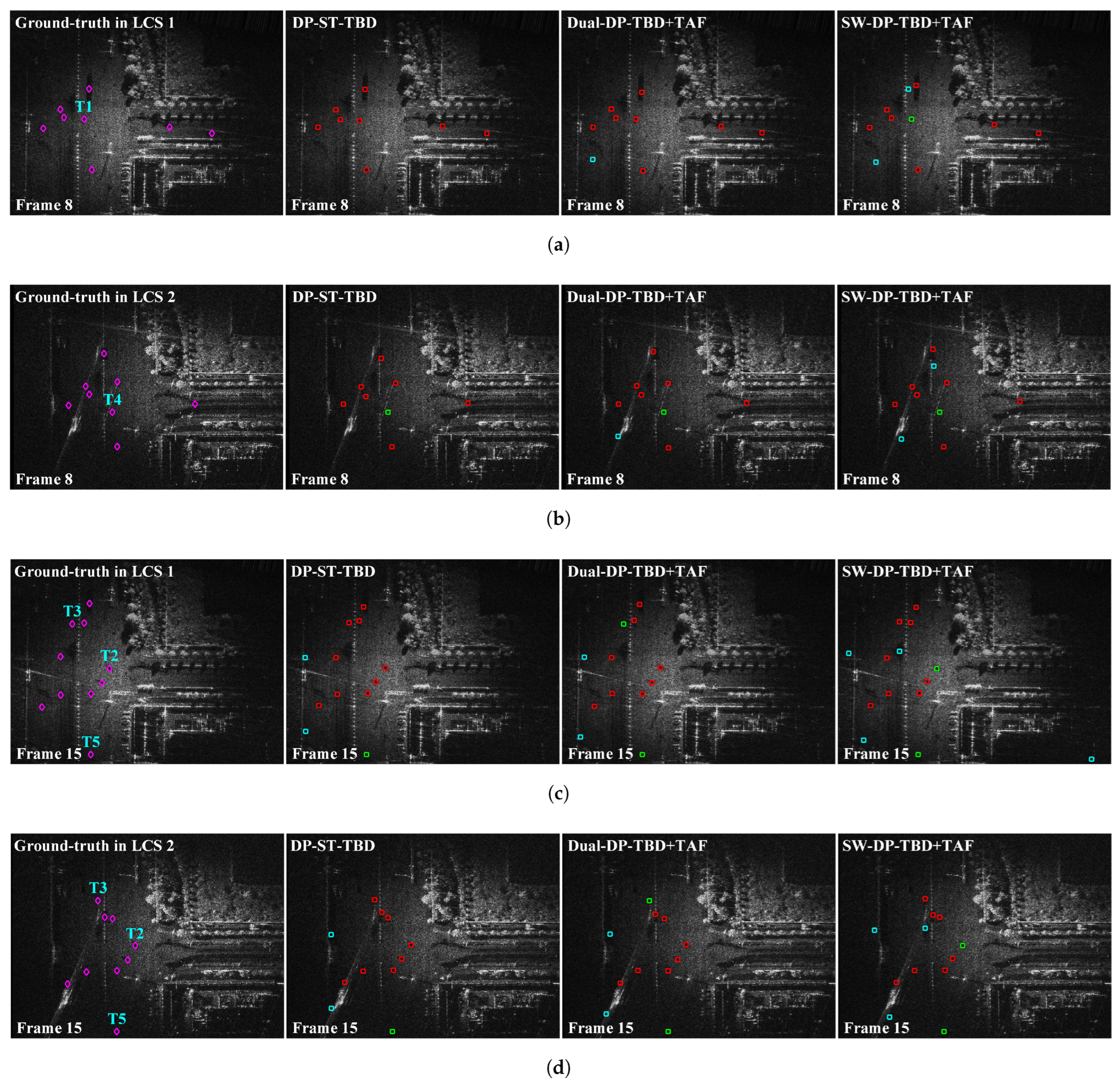
Figure 11 shows comparative analyses of detection results in Frame 8 and Frame 15. Each row displays (from left to right): shadow ground-truth, detection results of DP-ST-TBD, Dual-DP-TBD+TAF, and SW-DP-TBD+TAF algorithms, where red, green and cyan rectangles indicate correct detections, missed alarms, and false alarms, respectively. Due to the presence of platform-exclusive measured moving targets in the equivalent distributed video SAR data, the detection results of measured targets are separately annotated in their respective LCSs, whereas the detection results of simulated targets and generated false alarms are displayed simultaneously in both LCS SAR images. Quantitative detection results for all moving-target shadows are statistically presented in Table 2. The following metrics are used to evaluate the shadow-detection performance: (1) the number of correct detection N d ; (2) detection rate, p d , i.e., the ratio of the number of correctly detected shadows to the total number of shadows; (3) the number of false alarms, N f a ; (4) time cost used to measure the computational complexity of different algorithms.
The statistical results demonstrate that the proposed DP-ST-TBD algorithm significantly enhances shadow-detection performance by utilizing complementary measurements from different perspectives. As analyzed in Section 4.1, regions with significant contrast variations exist in the heterogeneous-view SAR images, primarily at image edges and the right road area shown in Figure 11. The missed alarms in compared methods mainly originate from the inaccurate state estimation, such as measured target T1 in Frame 8 and simulated targets T2 and T3 in Frame 15. Moreover, some missed alarms occur when newborn targets enter the observation scene within the detection window but are not detected promptly, such as measured target T4 in Frame 8 and simulated target T5 in Frame 15. Although reducing the sliding window step size could improve detection performance for newborn targets, it would also increase computational load.
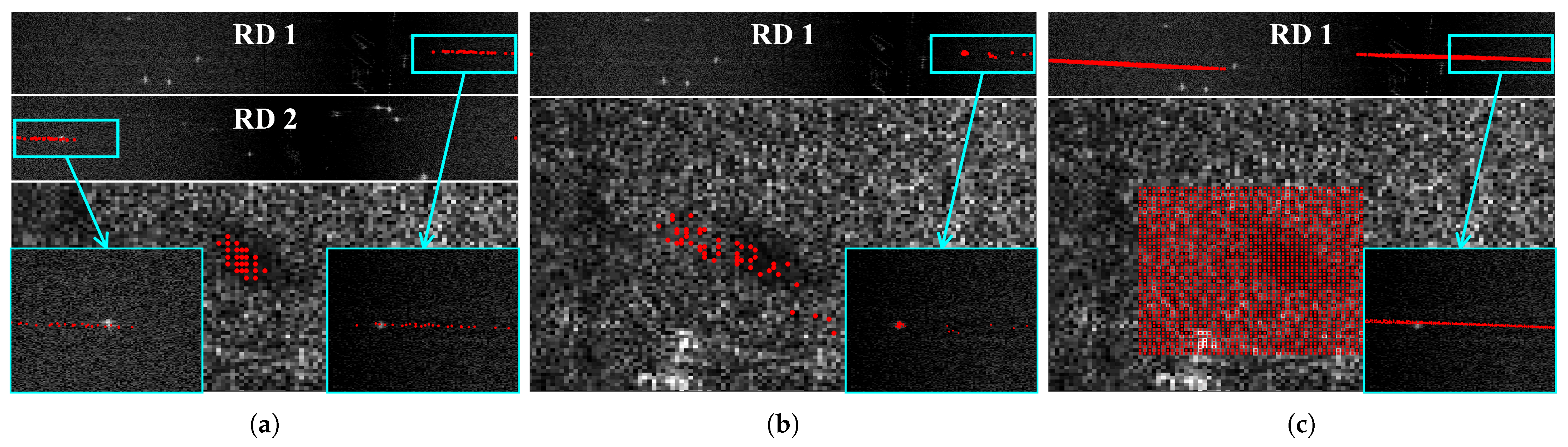
Figure 12 illustrates the differences in temporal dimension state transitions among three DP-TBD algorithms using a typical maneuvering target in Frame 12 as an example, where Figure 12a displays the predicted states obtained by the proposed DP-ST-TBD algorithm in both the GCS SAR image and dual-platform RD spectra. In the specific implementation of the state sparseness, an equidistant downsampling method with a step size of 2 in the image-domain X-Y plane is used, while retaining the specific row and column indices corresponding to the maximum accumulated value. Figure 12b,c present the predicted states obtained by Dual-DP-TBD and SW-DP-TBD algorithms shown in the LCS 1. It can be seen from Figure 12c that the conventional SW-DP-TBD algorithm produces regular and dense state distributions after multi-frame transitions. Although configuring a large number of acceleration process noise ( h n = 9 ) ensures comprehensive search coverage for maneuvering targets (states’ positions cover shadows and states’ velocities cover Doppler features), this approach imposes significant computational burdens. Moreover, the expanded states may cover other low-gray-level regions in SAR images, potentially causing interference to final detection decisions. Our previously developed Dual-DP-TBD algorithm addresses this problem by utilizing moving target’s Doppler features to guide velocity-constrained shadow searches in the SAR image. As shown in Figure 12b, the joint state refinement estimation during state initialization and transitions enable effective maneuvering target search. However, Dual-DP-TBD is vulnerable to the challenges posed by targets with low radial velocities or low RCS in single-view observations due to the reliance on single-platform dual-domain information.
To overcome these limitations, the proposed DP-ST-TBD algorithm implements two key innovations: (1) It employs the Doppler-aided adaptive state transition method detailed in Algorithm 3, which can achieve the robust search for maneuvering targets in a state space as small as possible. Meanwhile, it can enhance the transition reliability through utilizing multi-platform, dual-domain measurements. (2) The state shrinking–sparseness strategy is used to promptly eliminate invalid and redundant states, enabling effective multi-platform, multi-frame accumulation using sparse states and achieving a significant reduction in computational load.
Table 3 further analyzes the impact of different state transition methods on the detection performance of the proposed DP-ST-TBD algorithm. As described in Section 3.2, the conventional DP-TBD algorithm using a fixed-state transition method faces either insufficient or redundant states during target search, making it difficult to adaptively adjust the number of predicted states required per frame. When h n is fixed at 3, although the computational load of the DP-ST-TBD algorithm decreases substantially, its shadow detection rate deteriorates and cannot meet fundamental detection performance requirements. It sacrifices necessary detection rate in exchange for computational efficiency, which is generally unacceptable. When h n is fixed at 9, the DP-ST-TBD algorithm can ensure effective shadow detection based on adequate predicted states. However, this strategy incurs the significant increase in computational load and a higher risk of false detections to gain detection rate. As shown in Table 3, compared to the adaptive state transition method, its detection rate increased by only 0.48% (almost negligible), while false detections increased by 1.29 times and computational time increased by 1.57 times. Therefore, ensuring detection rate by simply increasing the number of states is inefficient and unstable. The proposed Doppler-aided adaptive state transition method achieves a balance between computational efficiency and detection performance, guaranteeing shadow detection rate requirements for video SAR GMTI with as little computational cost and false alarm risk as possible.

5. Discussion

The experimental results demonstrate several important findings regarding cooperative detection of moving-target shadow based on the distributed UAV-borne video SAR system. The proposed DP-ST-TBD approach outperforms the compared two-stage detection method, i.e., single-platform shadow detection using the state-of-the-art DP-TBD algorithms followed by multi-platform track fusion.
This paper first conducted a statistical analysis of the PDF of road clutter in the used heterogeneous-view SAR images, demonstrating that the Gaussian distribution more accurately characterizes the road clutter distribution. Subsequently, using the Gaussian distribution as an example, multi-platform, multi-frame joint accumulation performance was verified. To achieve the same detection performance, the required number of frames and platforms for the proposed DP-ST-TBD algorithm exhibits an inversely proportional relationship (when both the road clutter and shadows satisfy the i.i.d. condition in temporal and spatial dimensions) or a negative correlation (when the i.i.d. condition is not met). This phenomenon indicates the equivalence between spatial accumulation and temporal accumulation. Therefore, compared to conventional single-platform detection, multi-platform cooperative detection can reduce detection latency and alleviate the pressure of long-term motion state prediction for maneuvering targets.
Following this, a series of experiments were carried out to validate the performance of the proposed DP-ST-TBD algorithm on the used dataset. Multi-platform joint refinement estimation enhances the robustness of shadow state initialization, preventing initialization failures caused by shadow occlusion or the suppression of Doppler from slow-moving targets, and improves the estimation accuracy of the initial states. Notably, the adaptive state transition method and the state shrinking–sparseness strategy achieve a balance between computational efficiency and detection performance, enabling joint shadow detection in both temporal and spatial dimensions with low computational load. The final detection results show that the proposed DP-ST-TBD algorithm outperforms the compared methods in terms of detection rate, number of false detections, and computational time.

6. Conclusions

This paper proposes a DP-ST-TBD algorithm based on a distributed UAV-borne video SAR system, which establishes a spatiotemporal cooperative detection model for moving-target shadows. The proposed approach addresses the occlusion issue in single-view shadow detection through complementary heterogeneous-view measurements while reducing the number of required frames for reliable detection via multi-platform, multi-frame joint accumulation. Moreover, it incorporates a Doppler-aided adaptive state transition method and state shrinking–sparseness strategy, achieving robust maneuvering target detection with low computational complexity. Compared to existing two-stage detection methods, the proposed approach significantly enhances video SAR GMTI performance in complex terrain detection scenarios.

Author Contributions

Conceptualization, L.W.; methodology, L.W. and X.H.; software, L.W.; validation, M.K. and M.J.; formal analysis, L.W. and M.K.; investigation, M.J.; resources, J.D. and X.H.; writing—original draft preparation L.W. and M.K.; writing—review and editing, L.W.; supervision X.H. and J.D. All authors have read and agreed to the published version of the manuscript.

Funding

This work was partly funded by the Foundation of National Key Laboratory of Radar Signal Processing under Grant JKW202406, the National Natural Science Foundation of China under Grant 62401436, the Postdoctoral Fellowship Program of China Postdoctoral Science Foundation under Grant GZC20232054 and the National Natural Science Foundation of China under Grant 12203038.

Data Availability Statement

The raw data supporting the conclusions of this article will be made available by the authors on request.

Conflicts of Interest

The authors declare no conflicts of interest.

References

  1. Kim, S.H.; Fan, R.; Dominski, F. ViSAR: A 235 GHz radar for airborne applications. In Proceedings of the 2018 IEEE Radar Conference (RadarConf18), Oklahoma City, OK, USA, 23–27 April 2018; pp. 1549–1554. [Google Scholar]
  2. Palm, S.; Sommer, R.; Janssen, D.; Tessmann, A.; Stilla, U. Airborne Circular W-Band SAR for Multiple Aspect Urban Site Monitoring. IEEE Trans. Geosci. Remote Sens. 2019, 57, 6996–7016. [Google Scholar] [CrossRef]
  3. Kim, C.K.; Azim, M.T.; Singh, A.K.; Park, S.O. Doppler Shifting Technique for Generating Multi-Frames of Video SAR via Sub-Aperture Signal Processing. IEEE Trans. Signal Process. 2020, 68, 3990–4001. [Google Scholar] [CrossRef]
  4. Zhang, Y.; Zhu, D.; Mao, X.; Yu, X.; Zhang, J.; Li, Y. Multirotors Video Synthetic Aperture Radar: System Development and Signal Processing. IEEE Aerosp. Electron. Syst. Mag. 2020, 35, 32–43. [Google Scholar] [CrossRef]
  5. Gao, A.; Sun, B.; Li, J.; Li, C. A Parameter-Adjusting Autoregistration Imaging Algorithm for Video Synthetic Aperture Radar. IEEE Trans. Geosci. Remote Sens. 2022, 60, 5215414. [Google Scholar] [CrossRef]
  6. Pu, W.; Wu, J.; Huang, Y.; Yang, J. ORTP: A Video SAR Imaging Algorithm Based on Low-Tubal-Rank Tensor Recovery. IEEE J. Sel. Top. Appl. Earth Obs. Remote Sens. 2022, 15, 1293–1308. [Google Scholar] [CrossRef]
  7. An, H.; Wu, J.; Teh, K.C.; Sun, Z.; Li, Z.; Yang, J. Joint Low-Rank and Sparse Tensors Recovery for Video Synthetic Aperture Radar Imaging. IEEE Trans. Geosci. Remote Sens. 2022, 60, 5214913. [Google Scholar] [CrossRef]
  8. Cheng, Y.; Ding, J.; Sun, Z.; Zhong, C. Processing of Airborne Video SAR Data Using the Modified Back Projection Algorithm. IEEE Trans. Geosci. Remote Sens. 2022, 60, 5238013. [Google Scholar] [CrossRef]
  9. Huang, X.; Xu, Z.; Ding, J. Video SAR Image Despeckling by Unsupervised Learning. IEEE Trans. Geosci. Remote Sens. 2021, 59, 10151–10160. [Google Scholar] [CrossRef]
  10. Ai, J.; Wang, G.; Fan, G.; Wang, F.; Jia, L.; Wu, Y. A Trilateral Filter for Video SAR Speckle Noise Reduction. IEEE Geosci. Remote Sens. Lett. 2022, 19, 4508505. [Google Scholar] [CrossRef]
  11. Huang, X.; Ding, J.; Guo, Q. Unsupervised Image Registration for Video SAR. IEEE J. Sel. Top. Appl. Earth Obs. Remote Sens. 2021, 14, 1075–1083. [Google Scholar] [CrossRef]
  12. Tian, X.; Liu, J.; Mallick, M.; Huang, K. Simultaneous Detection and Tracking of Moving-Target Shadows in ViSAR Imagery. IEEE Trans. Geosci. Remote Sens. 2021, 59, 1182–1199. [Google Scholar] [CrossRef]
  13. Wu, Z.; Xie, H.; Gao, T.; Zhang, Y.; Liu, H. moving-target shadow Detection Method Based on Improved ViBe in VideoSAR Images. IEEE J. Sel. Top. Appl. Earth Obs. Remote Sens. 2024, 17, 14575–14587. [Google Scholar] [CrossRef]
  14. Sun, Z.; Wen, L.; Ding, J. Adaptive Frame-Rate Partitioned Video SAR. IEEE Trans. Radar Syst. 2025, 3, 576–590. [Google Scholar] [CrossRef]
  15. Zhao, B.; Han, Y.; Wang, H.; Tang, L.; Liu, X.; Wang, T. Robust Shadow Tracking for Video SAR. IEEE Geosci. Remote Sens. Lett. 2021, 18, 821–825. [Google Scholar] [CrossRef]
  16. Xu, Z.; Sun, J.; Wu, F. A Novel IMM Filter for VideoSAR Ground Moving Target Tracking. In Proceedings of the 2019 6th Asia-Pacific Conference on Synthetic Aperture Radar (APSAR), Xiamen, China, 26–29 November 2019; pp. 1–5. [Google Scholar]
  17. Liu, Z.; An, D.; Huang, X. moving-target shadow Detection and Global Background Reconstruction for VideoSAR Based on Single-Frame Imagery. IEEE Access 2019, 7, 42418–42425. [Google Scholar] [CrossRef]
  18. Ding, J.; Wen, L.; Zhong, C.; Loffeld, O. Video SAR Moving Target Indication Using Deep Neural Network. IEEE Trans. Geosci. Remote Sens. 2020, 58, 7194–7204. [Google Scholar] [CrossRef]
  19. Yang, X.; Shi, J.; Chen, T.; Hu, Y.; Zhou, Y.; Zhang, X. Fast Multi-Shadow Tracking for Video-SAR Using Triplet Attention Mechanism. IEEE Trans. Geosci. Remote Sens. 2022, 60, 5224212. [Google Scholar] [CrossRef]
  20. Yan, H.; Liu, H.; Xu, X.; Zhou, Y.; Cheng, L.; Li, Y.; Wu, D.; Zhang, J.; Wang, L.; Zhu, D. A New Method of Video SAR Ground Moving Target Detection and Tracking Based on the Interframe Amplitude Temporal Curve. IEEE Trans. Geosci. Remote Sens. 2023, 61, 5219217. [Google Scholar] [CrossRef]
  21. Bao, J.; Zhang, X.; Zhang, T.; Zeng, T.; Yang, Z.; Zhan, X.; Shi, J.; Wei, S. Shadow-Enhanced Self-Attention and Anchor-Adaptive Network for Video SAR Moving Target Tracking. IEEE Trans. Geosci. Remote Sens. 2023, 61, 5204913. [Google Scholar] [CrossRef]
  22. Fang, H.; Liao, G.; Liu, Y.; Zeng, C.; He, X.; Meng, Q. A Dual-Mode Framework for Robust Long-Term Tracking in Video SAR. IEEE Sens. J. 2024, 24, 13028–13042. [Google Scholar] [CrossRef]
  23. Zhang, W.; Zhang, X.; Xu, X.; Xu, Y.; Shao, Z.; Shi, J.; Wei, S.; Zeng, T. GNN-JFL: Graph Neural Network for Video SAR Shadow Tracking with Joint Motion-Appearance Feature Learning. IEEE Trans. Geosci. Remote Sens. 2024, 62, 5209117. [Google Scholar] [CrossRef]
  24. Fang, H.; Liao, G.; Liu, Y.; Zeng, C.; He, X.; Xu, M. A Joint Moving Target Detection Method in Video SAR via Low-Rank Sparse Decomposition and Transformer. IEEE J. Sel. Top. Appl. Earth Obs. Remote Sens. 2025, 18, 1007–1019. [Google Scholar] [CrossRef]
  25. Wen, L.; Ding, J.; Loffeld, O. Video SAR Moving Target Detection Using Dual Faster R-CNN. IEEE J. Sel. Top. Appl. Earth Obs. Remote Sens. 2021, 14, 2984–2994. [Google Scholar] [CrossRef]
  26. Qin, S.; Ding, J.; Wen, L.; Jiang, M. Joint Track-Before-Detect Algorithm for High-Maneuvering Target Indication in Video SAR. IEEE J. Sel. Top. Appl. Earth Obs. Remote Sens. 2021, 14, 8236–8248. [Google Scholar] [CrossRef]
  27. Wen, L.; Ding, J.; Cheng, Y.; Xu, Z. Dually Supervised Track-Before-Detect Processing of Multichannel Video SAR Data. IEEE Trans. Geosci. Remote Sens. 2022, 60, 5228713. [Google Scholar] [CrossRef]
  28. Zhong, C.; Ding, J.; Zhang, Y. Joint Tracking of Moving Target in Single-Channel Video SAR. IEEE Trans. Geosci. Remote Sens. 2022, 60, 5212718. [Google Scholar] [CrossRef]
  29. Zhong, C.; Ding, J.; Zhang, Y. Video SAR Moving Target Tracking Using Joint Kernelized Correlation Filter. IEEE J. Sel. Top. Appl. Earth Obs. Remote Sens. 2022, 15, 1481–1493. [Google Scholar] [CrossRef]
  30. Luan, J.; Wen, L.; Ding, J. Multifeature Joint Detection of Moving Target in Video SAR. IEEE Geosci. Remote Sens. Lett. 2022, 19, 4515805. [Google Scholar] [CrossRef]
  31. Wang, M.; Li, X.; Gao, L.; Sun, Z.; Cui, G.; Yeo, T.S. Signal Accumulation Method for High-Speed Maneuvering Target Detection Using Airborne Coherent MIMO Radar. IEEE Trans. Signal Process. 2023, 71, 2336–2351. [Google Scholar] [CrossRef]
  32. Gao, L.; Li, X.; Wang, M.; Sun, Z.; Cui, G.; Yeo, T.S. Multichannel Multiframe accumulation Detection Method for Weak Target with Coherent MIMO Radar. IEEE Trans. Aerosp. Electron. Syst. 2025, 61, 6518–6536. [Google Scholar] [CrossRef]
  33. Li, J.; Wen, L.; Yu, Z.; Ding, J. State Estimation of Moving Targets Using Sequential Range and Doppler Measurements with Swarm of UAV-Borne Radars. IEEE Trans. Aerosp. Electron. Syst. 2025, 61, 11904–11918. [Google Scholar] [CrossRef]
  34. Wang, Y.; Ding, Z.; Li, L.; Liu, M.; Ma, X.; Sun, Y.; Zeng, T.; Long, T. First Demonstration of Single-Pass Distributed SAR Tomographic Imaging with a P-Band UAV SAR Prototype. IEEE Trans. Geosci. Remote Sens. 2022, 60, 5238618. [Google Scholar] [CrossRef]
  35. Ren, H.; Sun, Z.; Yang, J.; Huang, C.; An, H.; Li, Z.; Wu, J. A Hybrid Resolution Enhancement Framework for Swarm UAV SAR Based on Cost-Effective Formation Strategy. IEEE Trans. Geosci. Remote Sens. 2024, 62, 5200216. [Google Scholar] [CrossRef]
  36. Ding, J.; Zhang, K.; Huang, X.; Xu, Z. High Frame-Rate Imaging Using Swarm of UAV-Borne Radars. IEEE Trans. Geosci. Remote Sens. 2024, 62, 5204912. [Google Scholar] [CrossRef]
  37. Yi, W.; Morelande, M.R.; Kong, L.; Yang, J. An Efficient Multi-Frame Track-Before-Detect Algorithm for Multi-Target Tracking. IEEE J. Sel. Top. Signal Process. 2013, 7, 421–434. [Google Scholar] [CrossRef]
Figure 1. Schematic diagram of limitations of the single-platform shadow DP-TBD. (a) Single-view shadow occlusion effects and low-gray-level interference. (b) Challenges of maneuvering target search and detection, where the yellow curves show the trajectory of a maneuvering target, red dots indicate its positions in each frame, and differently colored rectangular regions represent the state position distributions in different frames.
Remotesensing 18 00343 g001
Figure 2. Flowchart of the proposed DP-ST-TBD algorithm used for multi-platform, multi-frame cooperative shadow detection.
Remotesensing 18 00343 g002
Figure 3. Flowchart of the multi-platform joint refinement estimation.
Remotesensing 18 00343 g003
Figure 4. Early-stage velocity prediction errors lead to later-stage search failure.
Remotesensing 18 00343 g004
Figure 5. Imaging geometry of the distributed UAV-borne video SAR system, where the black rectangle represent the observation area.
Remotesensing 18 00343 g005
Figure 6. Experimental data demonstration of multi-platform, multi-frame cooperative detection. (a,b) First-frame SAR images of Platform 1 and Platform 2. (c,d) First-frame RD spectra of Platform 1 and Platform 2. The moving targets’ shadow and Doppler trajectories are shown in SAR images and RD spectra, respectively, including their initiation and termination frame indices (as indicated by the numbers in the figures). Identical colors represent the same targets. Cyan rectangles highlight typical regions with significant differences between two perspectives.
Remotesensing 18 00343 g006
Figure 7. Comparison between simulated and measured shadows.
Remotesensing 18 00343 g007
Figure 8. Measured inverse-amplitude PDFs and fitted distributions for road clutter. (a) Platform 1. (b) Platform 2.
Remotesensing 18 00343 g008
Figure 9. Performance analyses of the proposed DP-ST-TBD algorithm. (a,c) PDFs when road clutter and shadows follow identical and different Gaussian distributions between platforms, respectively. (b,d) Corresponding detection performance of single-platform multi-frame accumulation and multi-platform, multi-frame joint accumulation, respectively.
Remotesensing 18 00343 g009
Figure 10. Multi-platform joint refinement estimation results in the fifth detection window. (a) The local initial states in LCSs (red circles and green rectangles) and global preliminary initial states (purple circles) in GCS, where cyan boxes mark single-platform initialization failures and cyan diamonds are shadow ground-truths in GCS. (b,c) The refinement estimation results of two typical moving targets, where cyan points are the expanded states, green and red circles are the global preliminary and refined initial states, respectively.
Remotesensing 18 00343 g010
Figure 11. Comparative analyses of shadow detection results in typical frames. (a,b) Detection results in Frame 8. (c,d) Detection results in Frame 15. Each row displays (from left to right): shadow ground-truth, detection results of DP-ST-TBD, Dual-DP-TBD+TAF and SW-DP-TBD+TAF algorithms, where red, green, and cyan rectangles represent correct detections, missed alarms, and false alarms, respectively, purple diamonds represent shadow ground-truths.
Remotesensing 18 00343 g011
Figure 12. Comparative analyses of predicted states (red dots) of a maneuvering target in Frame 12. (a) Predicted states of the DP-ST-TBD algorithm shown in the GCS SAR image and RD spectra of two platforms (RD 1 and RD 2). (b,c) Predicted states of the Dual-DP-TBD and SW-DP-TBD algorithms shown in the LCS 1.
Remotesensing 18 00343 g012
Table 1. RMSE between fitted and measured inverse-amplitude PDFs.
No.GaussianGammaWeibull
Platform 10.01510.09640.0460
Platform 20.04010.11440.0543
Table 2. Comparison of detection performances of different algorithms.
AlgorithmShadowsCorrect Detection N d Detection Rate p d False Alarm N fa Time Cost (s)
SW-DP-TBD+TAF4193540.84497880.53
Dual-DP-TBD+TAF3800.90693624.91
DP-ST-TBD3960.94511718.35
Table 3. Comparison of detection performances of different state transition methods of the proposed DP-ST-TBD algorithm.
MethodShadowsCorrect Detection N d Detection Rate p d False Alarm N fa Time Cost (s)
Fixed-state transition ( h n = 3)4193610.8616174.86
Fixed-state transition ( h n = 9)3980.94992228.78
Adaptive state transition ( h n [ 3 , 9 ] )3960.94511718.35
Disclaimer/Publisher’s Note: The statements, opinions and data contained in all publications are solely those of the individual author(s) and contributor(s) and not of MDPI and/or the editor(s). MDPI and/or the editor(s) disclaim responsibility for any injury to people or property resulting from any ideas, methods, instructions or products referred to in the content.