Article

A Hybrid VRT-S-BR Method for Composite Electromagnetic Scattering from Targets Above Vegetated Rough Surfaces


1
School of Physics, Xidian University, Xi’an 710071, China
2
China Research Institute of Radiowave Propagation (The 22nd Research Institute of China Electronics Technology Group Corporation), Qingdao 266107, China
*
Author to whom correspondence should be addressed.
Remote Sens. 2026, 18(13), 2183; https://doi.org/10.3390/rs18132183
Submission received: 27 April 2026 / Revised: 20 June 2026 / Accepted: 23 June 2026 / Published: 4 July 2026

Highlights

What are the main findings?
  • A hybrid VRT-S-BR framework is developed by integrating an angle-indexed vegetation scattering database and a deterministic, facet-dependent phase compensation scheme into the ray-tracing process.
  • The model agrees well with field-measured backscattering data, with RMSE values of 1.82 dB and 3.10 dB for HH and VV polarizations, and reveals a nonlinear saturation behavior of target-vegetation coupled scattering with increasing vegetation coverage.
What is the implication of the main finding?
  • The proposed method provides a computationally efficient and physics-informed tool for predicting the radar cross-section (RCS) of complex targets in vegetation-covered cluttered environments.
  • These findings offer useful theoretical support for radar target detection, terrain-background scattering analysis, and bistatic scattering prediction, particularly for low-altitude targets above diverse vegetation-covered terrains.

Abstract

This paper proposes a hybrid Vector Radiative Transfer Shooting (VRT-S)-Bouncing Ray (BR) method, referred to as the VRT-S-BR method, for predicting composite electromagnetic scattering from targets above vegetation-covered rough surfaces. In this proposed framework, the vegetation layer is modeled as a stratified random medium and incorporated into the BR solver through VRT-S-derived amplitude modulation and deterministic phase compensation. Specifically, an offline database of vegetation-induced complex reflection coefficients is first generated using the VRT-S model over a set of incidence angles. During the BR ray-tracing process, these coefficients are used to replace the conventional Fresnel reflection terms on a per-interaction basis, thereby accounting for vegetation-induced attenuation and coherent scattering effects. In addition, a facet-dependent phase compensation scheme is introduced to describe propagation-path variations of individual rays through the vegetation canopy, avoiding the empirical random phase perturbation used in previous hybrid models. The proposed method is validated against field-measured backscattering data over natural grassland, achieving root mean square height (RMSE) values of 1.82 dB and 3.10 dB for horizontal-horizontal (HH) and vertical-vertical (VV) polarizations, respectively. Numerical results further demonstrate the capability of the method to characterize target–vegetation coupled scattering under different percentages of vegetation cover, vegetation heights, terrain backgrounds, and bistatic observation geometries.

1. Introduction

Research on composite electromagnetic (EM) scattering from targets above vegetated rough surfaces is of considerable significance in diverse fields selected examples of which include precision agriculture, wireless communications and military applications. Accurate modeling of such composite scenes supports radar-based target detection and recognition in cluttered environments, enables vegetation and soil parameter retrieval, and facilitates such as the monitoring crop growth and terrain assessment [1,2,3,4]. However, the coexistence of volumetric vegetation scattering, rough-surface scattering, and target-induced multiple interactions makes the underlying EM mechanism highly complex and computationally demanding.
Numerical full-wave methods, such as the Method of Moments (MoM) [5], Finite Element Method (FEM), Fast Hybrid Method (FHM) [6,7], and Finite Difference Time Domain (FDTD) [8], have been extensively employed for high-fidelity simulation of vegetation. Although these methods can provide rigorous solutions, their computational cost grows rapidly with the electrical size of the scene and the number of scatterers, especially when wide-area vegetation and rough ground are jointly considered. The FHM offers an efficient full-wave EM simulation of forests, particularly at the L-band, but it still requires substantial computational resources in terms of CPU time and memory [9]. In contrast, the Vector Radiative Transfer (VRT) method exhibits superior computational efficiency for vegetation scattering problems [10,11]. The VRT models the vegetation layer as a discrete medium composed of branches and leaves with various shapes, sizes, and orientations [12,13,14] and enables quantitative characterization of EM wave propagation, scattering, and absorption in complex media. As a result, it has shown particular efficacy in vegetation scattering analysis and related parameter studies [15,16,17,18,19,20,21,22,23].
Despite its efficiency for vegetation volumes, the VRT method exhibits limitations when applied to composite scattering scenarios involving vegetation-covered surfaces and man-made targets, where the coupled interactions among vegetation, ground, and targets can significantly affect both the amplitude and phase of the returned signals. Related semi-empirical and L-band radiative-transfer models, such as water-cloud, L-band Microwave Emission of the Biosphere (L-MEB), and forest radiometry formulations, provide useful vegetation parameterizations but are not designed to explicitly resolve target–vegetation multi-bounce coupling [24,25,26,27]. In such cases, it is necessary to incorporate complementary high-frequency techniques that can efficiently handle electrically large targets and multi-bounce interactions. The Bouncing Ray (BR) method is computationally efficient for predicting coupled EM scattering between rough surfaces and targets [28,29] and has been widely adopted for complex geometries under high-frequency conditions. Consequently, several studies have explored the integration of SBR and VRT to address composite scattering problems. For example, the facet-based modified two-scale model (FMTSM)–VRT–SBR method in [30] effectively solves the composite scattering problem for a target above vegetated ground. However, its treatment of target–vegetation interaction is simplified by introducing only a phase compensation based on a random parameter (between 0.5 and + 0.5 ). Such a coarse approximation cannot capture facet-dependent propagation and attenuation effects, and thus may limit the prediction accuracy when the target geometry is complex or when the vegetation layer is moderately to densely populated.
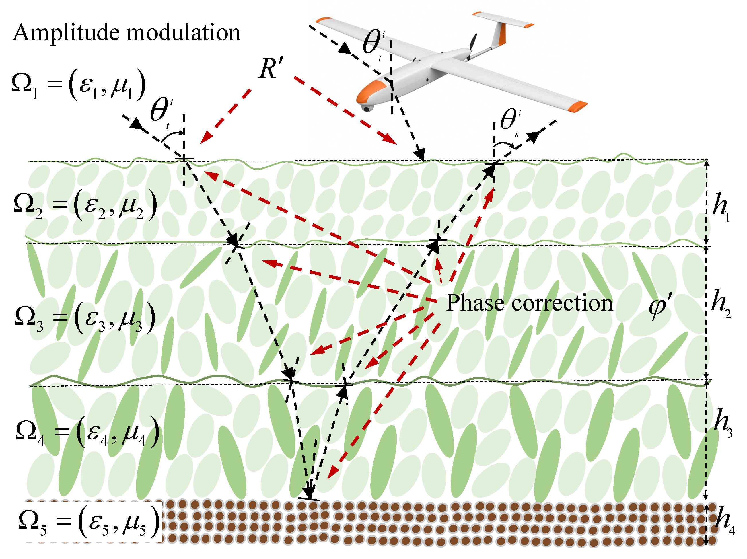
To overcome the above drawbacks, a new VRT-S-BR hybrid method is proposed and validated in this paper. The proposed method models the vegetation as a stratified (layered) medium and incorporates vegetation effects into the SBR framework through two key mechanisms: (1) Amplitude modulation: an offline database of vegetation scattering coefficients is generated using the VRT-S over a range of incidence angles, and these coefficients are then used to modify the Fresnel reflection coefficient in BR to account for vegetation-induced attenuation and scattering and (2), Phase compensation: since the path lengths traveled by rays through the vegetation layer depend on the reflection points on different target facets, phase compensation are applied by jointly considering the incidence angle and the vegetation height. With these treatments, the proposed method provides an efficient and physics-informed approach for composite scattering prediction in vegetation-covered scenes.
The main contributions of this paper are twofold: (1) a VRT-informed modification of the Fresnel reflection term in SBR using a precomputed vegetation-scattering database to account for vegetation-induced amplitude effects, and (2) a facet-dependent phase compensation that considers propagation path-length variations through the vegetation layer. The remainder of this paper is organized as follows: Section 2 details the proposed VRT–S–BR method, Section 3 presents validation and numerical results, and Section 4 concludes the paper.

2. VRT-S-BR Hybrid Method

2.1. Traditional VRT Method

The VRT constitutes a fundamental framework for studying the scattering, absorption, and propagation of polarized electromagnetic waves in random media and particularly relevant for complex environments such as vegetation [31,32,33]. To model the propagation of electromagnetic waves through vegetation, a simplified version of the Michigan Microwave Canopy Scattering (MIMICS) model is employed. This simplified model omits the trunk layer, retaining solely the vegetation and ground layers [34,35]. This simplification facilitates a more focused analysis of the scattering processes within the vegetation canopy. The VRT formulation describing electromagnetic wave propagation through this simplified MIMICS model can be expressed as:
d   I ¯ ( r ¯ , s ^ ) d s = K ¯ ¯ e · I ¯ ( r ¯ , s ^ ) + 4 π d Ω   P ¯ ¯ ( r ¯ , s ^ , s ^ ) · I ¯ ( r ¯ , s ^ )
where I ¯ ( r ¯ , s ^ ) denotes the Stokes intensity vector at position r ¯ along the propagation direction s ^ , r ¯ is the position vector, s ^ is the propagation direction of the electromagnetic wave, s ^ represents the incident direction contributing to the scattering integral, and d Ω is the differential solid angle. In addition, K ¯ ¯ e represents the extinction matrix, and P ¯ ¯ denotes the phase matrix. The zero-order solution of this VRT equation corresponds to the sole scattering from the ground layer. The backscattering coefficient for the ground can be expressed as:
σ p q g ( k ^ s , k ^ i ) = L p ( θ s ) σ p q s ( θ s , ϕ s ; θ i , ϕ i ) L q ( θ i )
where L q ( θ i ) represents the attenuation factor for a q-polarized wave passing through the vegetation layer along the incident direction, and σ p q s is the bistatic scattering coefficient of the ground. The subscripts p and q represent the polarization unit vectors of the scattering wave and the incident wave, respectively. The attenuation factor is defined as:
L q ( θ i ) = exp K e q ( θ i ) d sec θ i
The first-order solution of the VRT equation yields a backscattering coefficient consisting of three terms:
σ p q 1 = σ p q c + σ p q cg + σ p q gc
where σ p q c represents the scattering coefficient of the vegetation, while σ p q cg and σ p q gc are the scattering coefficients associated with the interaction between the vegetation and the ground respectively. These terms are given by:
σ p q c ( k ^ s , k ^ i ) = 4 π   P p q ( θ s , φ s ; π θ i , φ i ) 1 L p ( θ s ) L q ( θ i ) K e p ( θ s ) sec θ s + K e q ( θ i ) sec θ i
P p q = m = 1 N n m | F p q ( k ^ s , k ^ i ) | m 2
where P p q is the ( p , q ) component of the phase matrix.
σ p p gc = d sec θ i P p q ( θ i , π + ϕ i ; θ i , ϕ i ) σ c p s L p ( θ i ) L p ( θ i )
In Equation (7), the term σ p p gc accounts for the ground–canopy interaction, where σ c p s denotes the coherent scattering coefficient of the ground and by building on the reciprocity theorem, σ p q cg = σ p q gc .
Considering only the zeroth and first-order solutions of the VRT equation, the total scattering coefficient of the two-layer structure (vegetation and ground) is:
σ p q = σ p q g + σ p q c + σ p q cg + σ p q gc

2.2. SBR Method

The SBR method, initially developed for modeling scattered fields from cavity targets, is advantageous due to its simplicity, low computational complexity, and high accuracy [36,37,38]. This method integrates Geometrical Optics (GO) and Physical Optics (PO), utilizing GO for ray tracing in complex geometries and PO for calculating the induced electromagnetic currents on the target surface. Consequently, the total scattered field can be expressed as:
E total = n i = 1 N n E i , PO
In Equation (9) above, the first summation represents the accumulation over each ray tracing order (bounce), while the second summation accumulates the scattered fields from each illuminated triangular surface patch under the n-th ray tracing order. The variable N n represents the number of illuminated patches for the n-th ray tracing order.
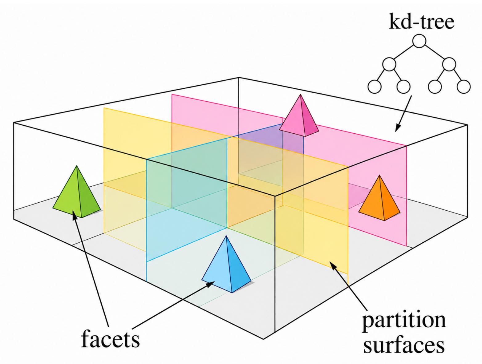
To accelerate the ray–facet intersection judgment in the GO ray-tracing procedure, a k-dimensional tree (kd-tree) data structure is employed. Each non-leaf node of the kd-tree generates an axis-aligned partition surface to divides the target space into two subspaces, as shown in Figure 1. These partition surfaces are determined based on the spatial distributions of triangular facets so that the facets are grouped into locally compact regions and the tree remains approximately balanced. The subspaces are organized according to their positional relationships, which provide domain information for fast traversal. The ray-tracing efficiency is further improved by first determining which subspace the ray intersects in a front-to-back manner, and by exclusively performing intersection and occlusion (shadowing) checks on the facets contained in the visited nodes. This decomposition strategy significantly reduces the number of candidate facets to be tested and enables efficient evaluation of the illuminated set and the corresponding E i , PO contributions at each bounce order.
For a PEC target, the far-field scattered electric field can be approximated as:
E s j k exp ( j k R ) 4 π R E a η H a × s ^
where E a and H a are respectively defined as:
E a = s ^ × M exp j k r · ( i ^ s ^ ) d s
H a = s ^ × J exp j k r · ( i ^ s ^ ) d s
The induced electric current density J and induced magnetic current density M , generated by the incident wave on the triangular surface patches, are respectively given by:
J = 1 η E TE cos θ   ( 1 R TE )   e ^ TE + E TM ( 1 R TM ) ( n ^ × e ^ TE ) | s
M = E TE ( 1 + R TE ) e ^ TM + E TM cos θ   ( 1 + R TM )   e ^ TE | s
where η is the spatial wave impedance, and θ is the local incident angle between the incident wave and the surface normal n ^ at the point of incidence. E TE and E TM denote the TE and TM components of the incident electric field E i , respectively; e ^ TE and e ^ TM are the unit direction vectors for TE and TM modes; and R TE and R TM correspond to the surface reflection coefficients, which can be written as follows:
R TE = cos θ ε r sin 2 θ cos θ + ε r sin 2 θ
R TM = ε r sin 2 θ ε r cos θ ε r sin 2 θ + ε r cos θ

2.3. Hybridization Strategy of VRT and S-BR

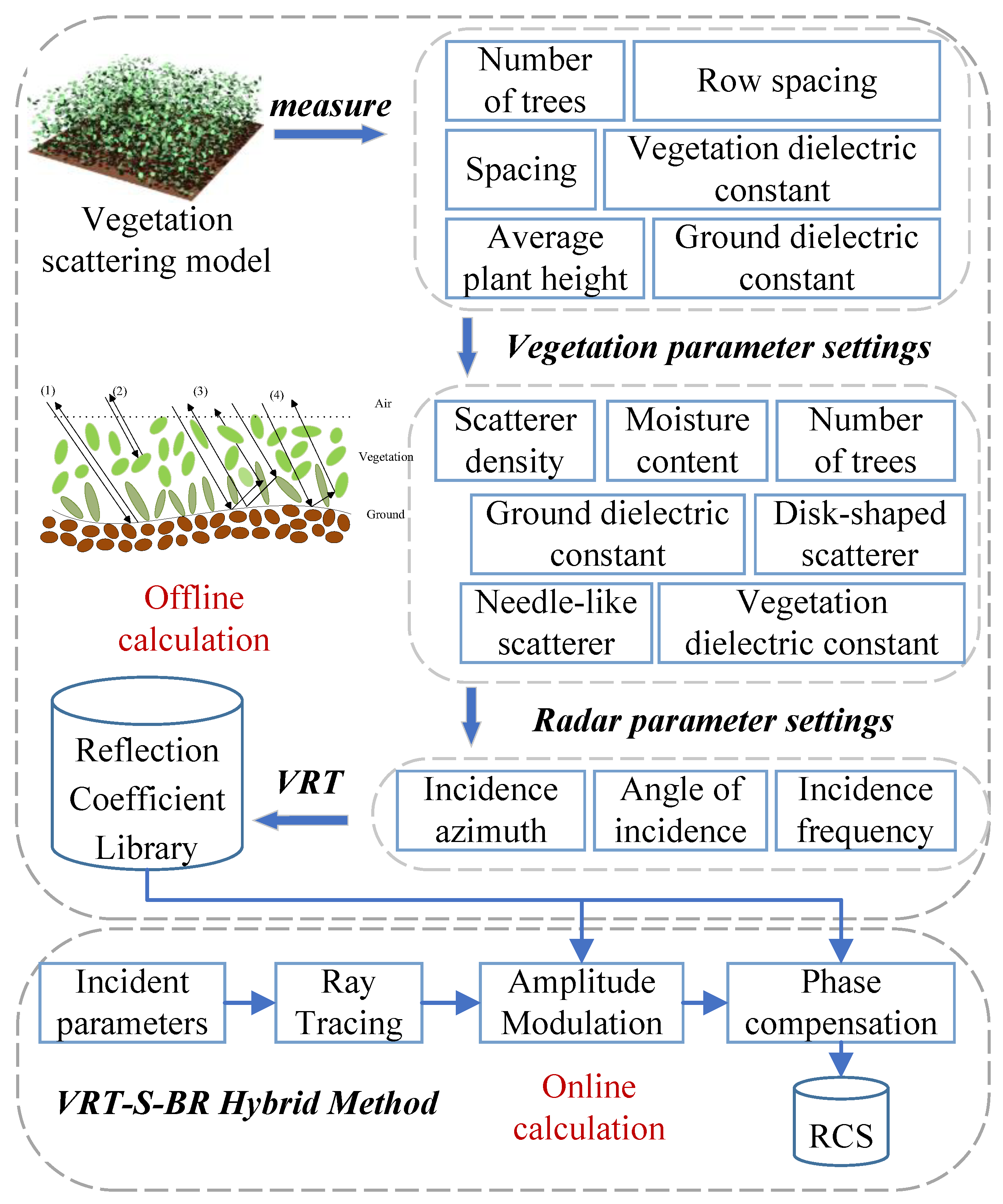
As illustrated in Figure 2, the proposed VRT–S–BR method models the vegetation as a stratified medium and embeds its effects into the SBR framework through two key mechanisms: (1) amplitude modulation, modifying the Fresnel reflection term with VRT-computed scattering coefficients, and (2) phase compensation, accounting for facet-dependent propagation path lengths through the vegetation layer.

2.3.1. Amplitude Modulation via a VRT-Computed Complex Reflection Database

To physically characterize the vegetated ground, the VRT model is first executed offline under a discrete set of incidence angles and a prescribed vegetation/ground parameter set p . For each incidence angle θ , the macroscopic vegetation effects are quantified by defining an effective complex reflection coefficient:
R ˜ q ( θ ; p ) R ˜ q ( θ ; p ) exp j   R ˜ q ( θ ; p ) , q { TE , TM } ,
where R ˜ q accounts for vegetation-induced attenuation and effective coherent loss/gain, and R ˜ q represents the net phase delay. These coefficients are then stored in an angle-indexed discrete look-up table, denoted as D = θ m , R ˜ TE ( θ m ; p ) , R ˜ TM ( θ m ; p ) m = 1 M .
During the subsequent SBR ray-tracing execution, each ray–facet interaction dynamically establishes a local plane of incidence. Once the local incidence angle θ is determined from the ray geometry, the algorithm retrieves the corresponding R ˜ TE ( θ ) and R ˜ TM ( θ ) from the precomputed database D . Finally, to account for the vegetation effects, the standard Fresnel expressions in Equations (15) and (16) are directly substituted by the following effective coefficients on a per-interaction basis:
R TE ( θ ) R ˜ TE ( θ ) , R TM ( θ ) R ˜ TM ( θ ) .

2.3.2. Facet-Dependent Phase Compensation

To establish the correspondence between vegetation physical properties and model inputs, Ulaby’s dual-dispersion model [13] is adopted to characterize the effective permittivity of the vegetation medium, as shown in Equation (19).
ε r = ε n + v f w 4.9 + 75.0 1 + j f / 18 j 18 σ f + v b 2.9 + 55.0 1 + ( j f / 0.18 ) 0.5 ,
where ε n is the permittivity of the dry matter, v f w and v b denote the volume fractions of free water and bound water, respectively, σ is the effective ionic conductivity, and f is the frequency in GHz.
Based on the vertical morphology of the canopy, the vegetation layer can be treated as a stratified medium, as illustrated in Figure 3. The local propagation directions of rays at layer boundaries are determined from Snell’s law:
ε i μ i   sin θ i = ε i + 1 μ i + 1   sin θ i + 1 ,
k ^ t = k 0 ε i + 1 μ i + 1 sin θ i + 1 x ^ + cos θ i + 1 z ^ .
For the target–vegetation-covered rough surface coupling path illustrated in Figure 3, ray propagation within the vegetation canopy is described using the stratified-medium formulation given above. After an incident ray reaches a rough-surface facet through the vegetation layer, the reflected direction is determined by the local specular reflection law:
k ^ r = k ^ i 2 ( k ^ i · n ^ g ) n ^ g ,
where k ^ i and k ^ r are the incident and reflected ray directions at the rough-surface facet, respectively, and n ^ g denotes the local normal vector of the corresponding facet. The reflected ray is subsequently traced through the vegetation layer toward the target. A valid coupling path is identified when the ray intersects the target mesh and satisfies the visibility condition. The scattering direction from the rough surface to the target is defined as
k ^ s = r t r g r t r g ,
where r g is the reflection point on the rough surface and r t is the corresponding intersection point on the target. Accordingly, the scattering angle θ s is obtained as
θ s = cos 1 k ^ s · n ^ g .
Owing to the reciprocity of the ray path, θ s can be equivalently determined from the reverse tracing path from the target intersection point to the rough-surface reflection point. In the present simulations, the maximum macroscopic bounce order between the target and the vegetation-covered rough surface is set to n max = 3 , while the propagation, attenuation, and phase variation within the stratified vegetation layer are evaluated along each valid ray path.
In the FMTSM–VRT–SBR method [30], the phase compensation is simply modeled using a random perturbation term, which does not explicitly account for the actual propagation difference of individual rays through the vegetation layer. As a consequence, the phase variation associated with different facet locations and ray trajectories cannot be rigorously captured. In contrast, the proposed VRT-S-BR method introduces a deterministic and facet-dependent phase compensation scheme in which, the complex phase compensation is directly linked to the local incidence geometry, the facet position, and the BR-derived propagation path. In this way, the vegetation-induced phase delay is no longer treated empirically but is instead incorporated in a physically consistent manner.
According to the different propagation configurations associated with the incident and scattered paths, three representative complex phase terms are introduced for compensation:
( i ) ϕ 1 = k q θ i , ϕ i k p θ s , ϕ s · R n + j ( R ˜ TE ) n cos θ i H n + ( R ˜ TM ) n cos θ s H n , ( ii ) ϕ 2 = k q θ i , ϕ i k p π θ s , ϕ s · R n + 2 k 0 H cos θ i + j ( R ˜ TE ) n cos θ i 2 H H n + ( R ˜ TM ) n cos θ s H n , ( iii ) ϕ 3 = k q π θ i , ϕ i k p π θ s , ϕ s · R n + 2 k 0 H cos θ i .
where R n denotes the position vector of the n-th interaction point associated with the corresponding surface element, H is the vegetation height, and H n denotes the path-length difference of the n-th ray relative to a reference propagation path. In addition, k q ( θ i , ϕ i ) and k p ( θ s , ϕ s ) denote the wave-vector components associated with the incident and scattering directions, respectively. The quantities ( R ˜ TE ) n and ( R ˜ TM ) n are the VRT-computed complex specular reflection coefficients for the TE and TM components, respectively. Therefore, compared with random phase perturbation models, the proposed formulation enables the phase compensation to explicitly follow the facet-dependent in-canopy propagation difference, which is more suitable for describing coherent target–vegetation interactions in complex composite scattering scenarios.

2.4. Overall Workflow

The implementation procedure of the proposed VRT–SBR method can be summarized as follows:
1.
Offline stage: Run the VRT model to construct the database D for the prescribed parameter set p .
2.
Online SBR stage: Build a kd-tree for the target mesh to accelerate ray–facet intersection tests, and perform ray tracing up to the maximum bounce order n max .
3.
Per interaction: Determine the local incidence geometry and TE/TM basis, interpolate R ˜ TE / TM from D , and apply both coefficient replacement and facet-dependent phase compensation before evaluating the corresponding E i , PO contribution.
4.
Field/RCS synthesis: Coherently sum the scattered-field contributions from all illuminated facets and bounce orders to obtain the total scattered field and the desired RCS.

2.5. Validation of the VRT-S-BR Hybrid Method

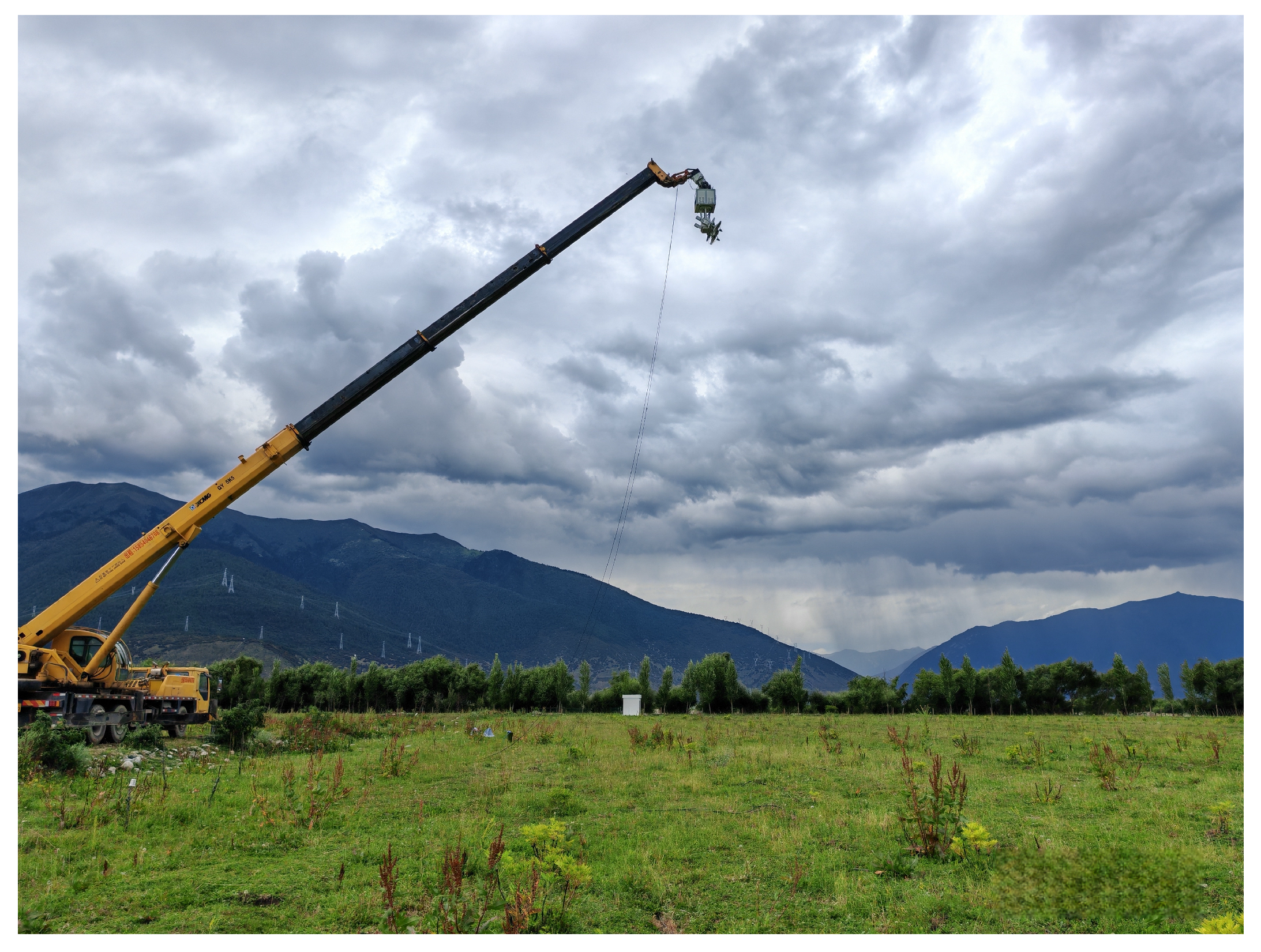
To validate the physical accuracy of the proposed VRT–S–BR hybrid method, field-measured backscattering data collected over a natural grassland are used. The measurement setup is illustrated in Figure 4. To suppress edge diffraction and reduce interference from the surrounding environment, the radar-illuminated area is restricted to a relatively homogeneous region of the grassland.
In the simulation, the field measurement data available for validation in this study include only the electromagnetic scattering response of the target-free vegetation background, whereas the proposed VRT-S–BR method is designed for composite electromagnetic scattering from a target above a vegetation-covered rough surface. To enable comparison with the available target-free measurement while preserving the computational workflow of the proposed composite-scattering framework, a very small auxiliary sphere with a radius of 1.0 × 10 6   m is placed above the vegetated ground. Owing to its extremely small radius, the scattering contribution of this auxiliary sphere is sufficiently small compared with the vegetation-covered ground response. Therefore, the simulated results can be used to approximate the target-free backscattering response of the vegetated surface. The incidence angle is set to θ i = 45 .
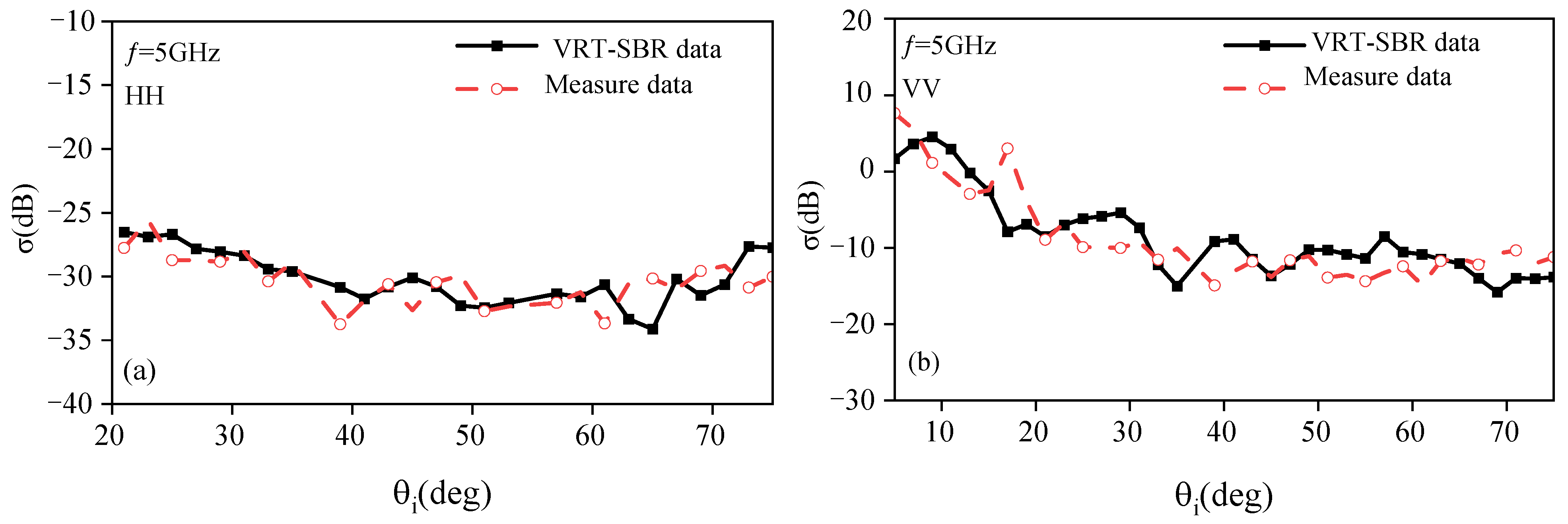
The VRT-S-BR predictions are compared with the measured data in Figure 5, where panels (a) and (b) correspond to HH and VV polarizations, respectively. Although minor discrepancies remain due to the inherent randomness of natural vegetation, the simulated curves capture the overall trends of the measurements well. The RMSE values of 1.82 dB (HH) and 3.10 dB (VV) further indicate that the proposed method provides reasonable quantitative agreement with the measurements [39,40]. This validation supports the use of the proposed method for the subsequent investigation of complex target–background composite scattering in vegetation-covered environments.

3. Results and Analysis

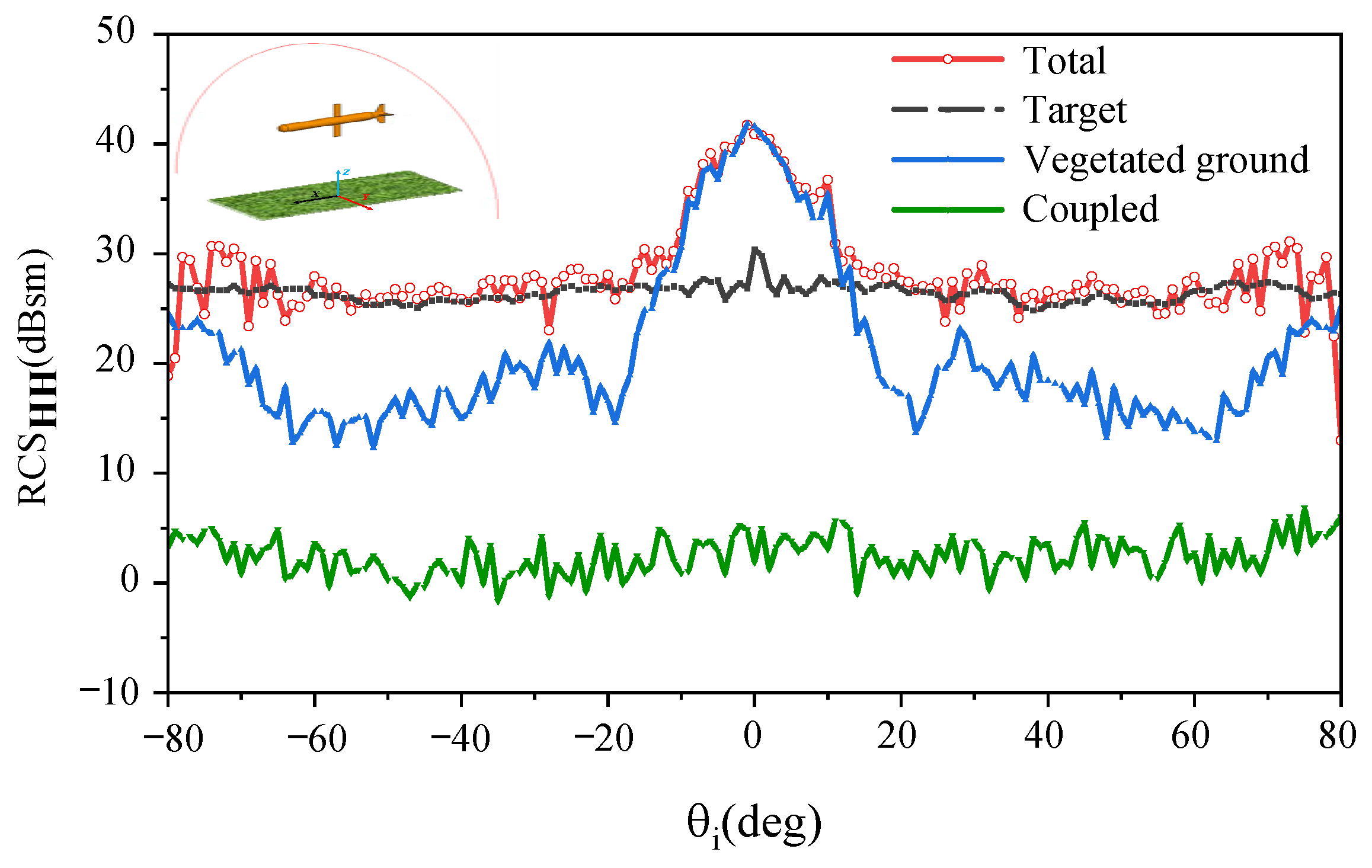
Figure 6 presents the backscattering RCS of a vegetated ground with a missile positioned 10 m above it, calculated using the proposed VRT-S-BR method under L-band conditions: a frequency of f = 1.34   GHz , HH polarization, and a 90 azimuthal incidence angle. The vegetated ground covers an area of 10   m × 10   m , while the missile-shaped target model has a length of 5.5   m and a radius of 0.5   m . The detailed parameters for the vegetated ground are provided in Table 1.
As shown in Figure 6, for larger incident angles ( θ i > 20 ), the total scattering RCS closely resembles that of the target, indicating that the target scattering dominates within this angular range. Conversely, for smaller incident angles ( θ i < 20 ), the total backscattering is primarily contributed by the vegetated ground. The coupled backscattering RCS remains approximately 5 dBsm across all incident angles. This is attributed to the fixed incident azimuth angle of 90 , resulting in a consistent target profile regardless of the incident elevation angle.
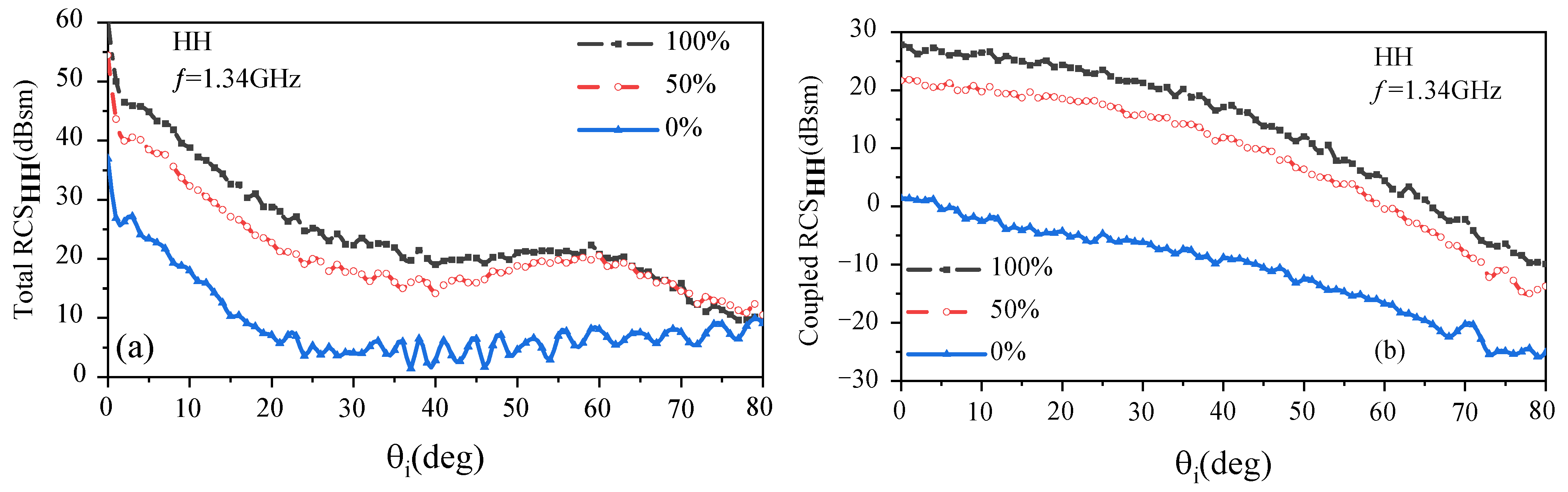
Figure 7 shows the comparison of RCS for different percentages of vegetation cover (0%, 50%, and 100%) simulated using the VRT-S-BR method. In this study, the vegetation coverage rate is implemented by changing the number densities of stems and leaves, rather than by changing the vegetation-covered area. Specifically, the 100% vegetation coverage case uses the original stem and leaf densities, the 50% vegetation coverage case uses half of these densities, and the 0% vegetation coverage case is modeled by setting the stem and leaf densities to zero. The individual vegetation geometry, moisture contents, orientation distributions, vegetation-covered area, and ground parameters are kept unchanged among the three cases.The corresponding vegetation and ground parameters are listed in Table 2. The incident frequency is set to 1.34 GHz, and the incident azimuth angle is set to 0 .
As shown in Figure 7a, for smaller incident angles ( θ i < 60 ), the total backscattering RCS increases as the vegetation coverage increases. This is because the increase in vegetation coverage leads to enhanced coupling scattering (i.e., the scattering interaction between the vegetation layer and the target). For larger incident angles ( θ i > 60 ), the total backscattering RCS for percentages of vegetation cover of 50% and 100% is similar. This is attributed to the reduced contribution of coupled scattering between the vegetated ground and the target at larger incident angles. For a more comprehensive understanding of the impact of percentages of vegetation cover on composite scattering, a comparison of the coupled scattering RCS for varying vegetation coverage is illustrated in Figure 7b. The results show two key trends: (1) the coupled scattering RCS decreases monotonically with increasing incidence angle at all vegetation coverage levels; (2) the increase in the coupled scattering RCS with vegetation coverage shows a nonlinear variation. Specifically, the increase observed when vegetation cover rises from 0% to 50% significantly exceeds that observed during the transition from 50% to 100%. This trend suggests that the initial introduction (0–50%) of vegetation primarily drives the change in scattering characteristics, while a saturation effect occurs at higher coverage levels (50–100%).
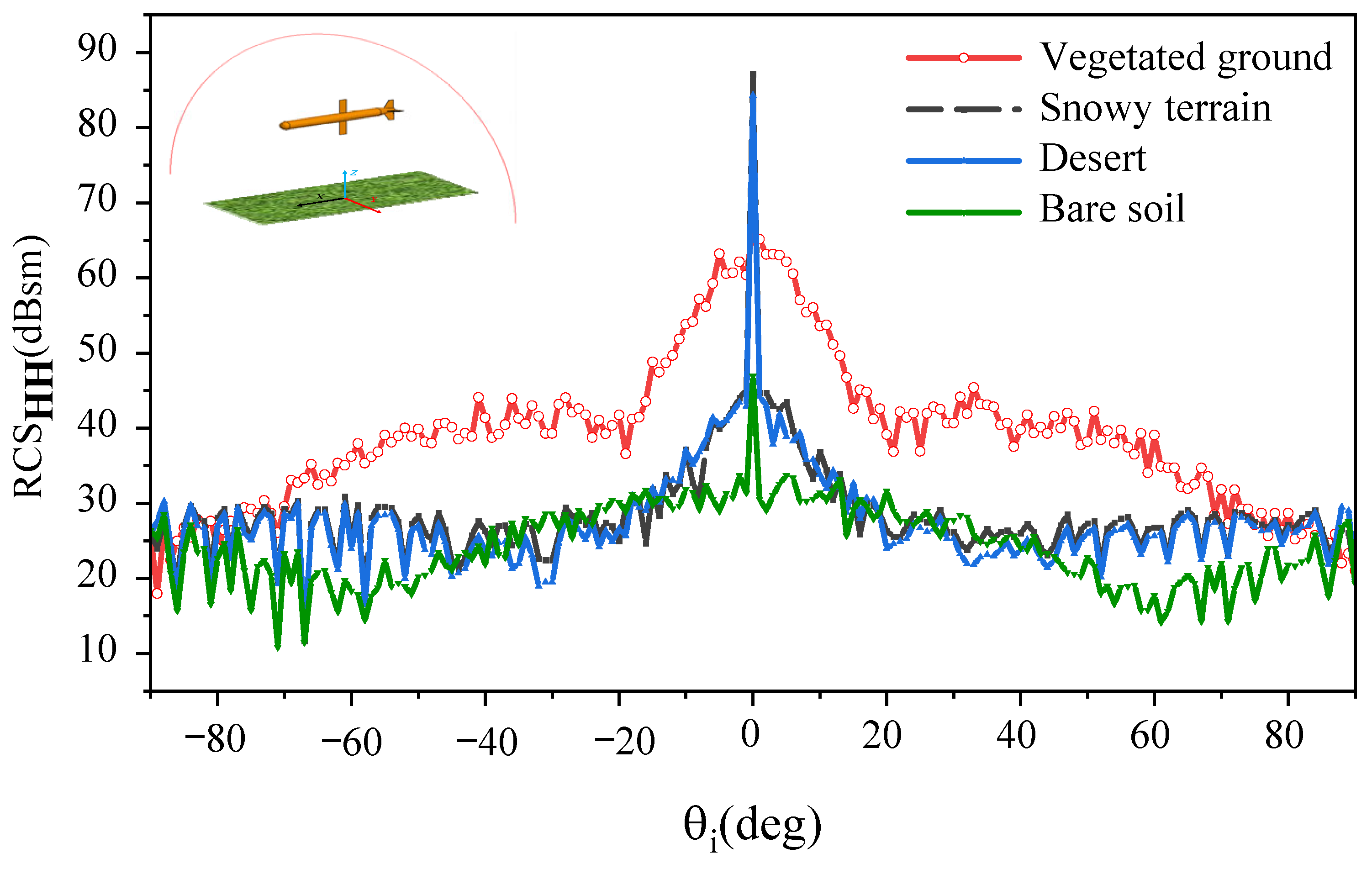
Figure 8 presents the differential RCS of a missile-shaped target model positioned above four distinct terrain types: vegetated ground, snowy terrain, desert, and bare soil. The simulations were conducted using the VRT–S–BR method under S-band conditions ( f = 3.2   GHz , HH polarization, ϕ i = 0 ). The geometric, statistical, and dielectric parameters of these ground surfaces are listed in Table 3. The differential RCS is defined as σ diff = σ total σ target , representing the composite scattering RCS with the target’s contribution subtracted.
As illustrated in Figure 8, the scattering responses vary markedly across the four terrains, closely correlating with the roughness parameters detailed in Table 3. Both the snowy terrain and desert exhibit pronounced specular characteristics, featuring a sharp peak near normal incidence ( θ i = 0 ). Owing to their minimal RMS heights ( 0.01   m and 0.015   m , respectively), the differential RCS is dominated by coherent specular reflection from the smooth background surfaces. As the incidence angle deviates from the specular direction, this coherent contribution drops rapidly, resulting in steep attenuation beyond the specular region ( | θ i | > 10 ).
Conversely, the vegetated ground exhibits a broad, diffuse scattering pattern. Although its specular peak is suppressed relative to the smoother terrains, the differential RCS sustains a high magnitude ( 40 60   dBsm ) over a wide angular range ( | θ i | < 40 ). This behavior is primarily driven by volume scattering within the vegetation canopy and diffuse electromagnetic coupling between the vegetation layer and the missile-shaped target model. Acting as discrete scatterers with random orientations, the stems and leaves multidirectionally redistribute the incident waves, thereby enhancing the scattering response at oblique angles.
Finally, the bare soil presents the lowest overall scattering intensity in the non-specular regions. Lacking both the volume scattering mechanism inherent to vegetation and the high surface smoothness of snow or desert, it generates neither strong diffuse scattering nor intense coherent reflection. These comparative results demonstrate the capability of the proposed VRT-S-BR method to accurately characterize the complex scattering mechanisms associated with diverse environmental backgrounds.
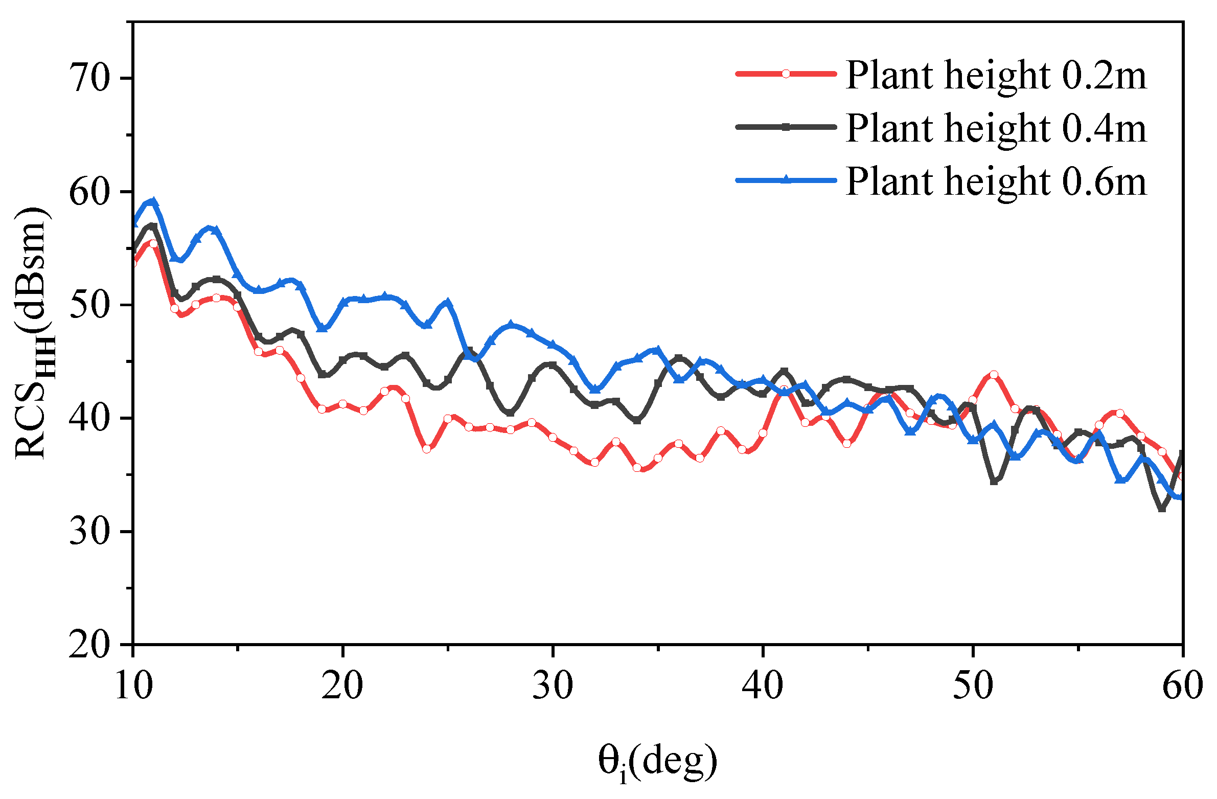
To further investigate the impact of vegetation height on the scattering behavior, three vegetated ground models with varying plant heights are established. The remaining geometric and physical parameters are kept constant, as detailed in Table 4. Based on these configurations, Figure 9 presents the simulated backscattering RCS HH at f = 1.34   GHz and θ i = 90 for the three vegetation samples.
As shown in Figure 9, the backscattering RCS HH exhibits a downward trend with increasing incidence angle θ i , accompanied by local oscillatory fluctuations resulting from the coherent superposition of various scattering contributions. The influence of vegetation height is particularly pronounced in the lower-to-intermediate angular range ( 10 θ i 40 ). This behavior indicates that increasing vegetation height enhances the contributions of canopy volume scattering and canopy–ground electromagnetic interaction. By contrast, for larger incidence angles ( θ i > 40 ), the three curves gradually converge, implying that the sensitivity of the backscattering response to vegetation height becomes weaker in the large-angle region.
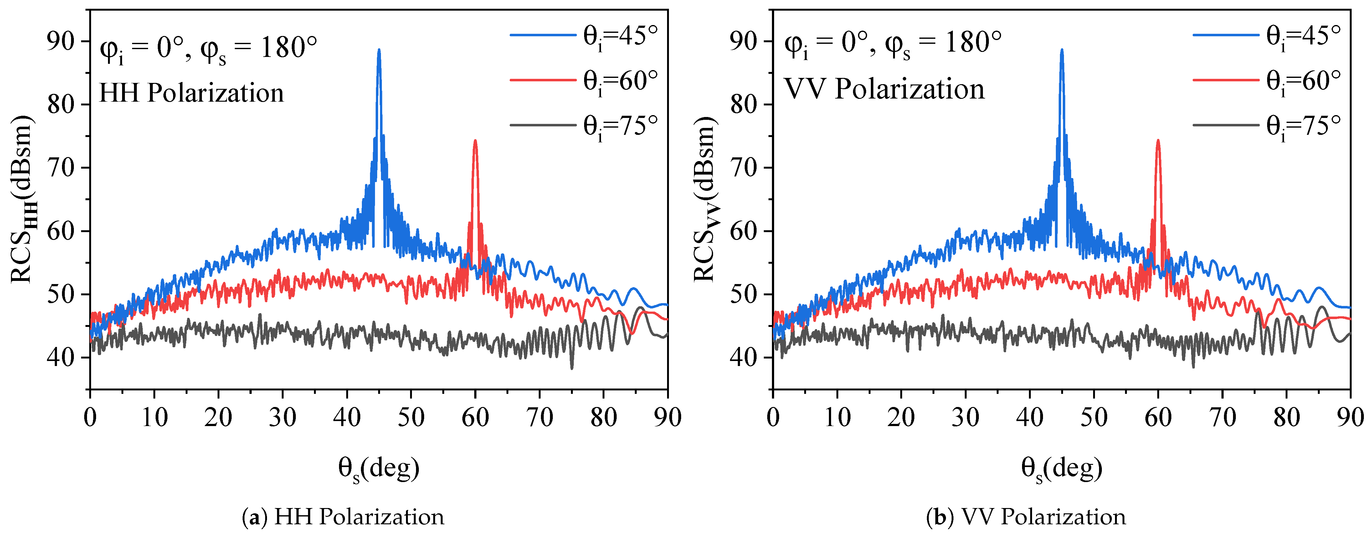
To extend the analysis beyond monostatic backscattering, the in-plane bistatic RCS is simulated at three intermediate incidence angles: θ i = 45 , 60 , and 75 .
The observation is restricted to the specular plane ( φ i = 0 and φ s = 180 ). Under these configurations, Figure 10 illustrates the bistatic scattering responses for both HH and VV polarizations.
As shown in Figure 10, for the incidence angles of θ i = 45 and 60 , clear specular peaks can be observed near the corresponding specular scattering directions. This indicates that, under these geometries, the coherent component associated with the background surface and its interaction with the vegetation layer still makes a non-negligible contribution to the total bistatic response. Meanwhile, noticeable diffuse scattering is present away from the specular direction, reflecting the combined effects of vegetation volume scattering, canopy–ground interaction, and surface roughness modulation.
As the incidence angle increases from 45 to 60 , both the specular peak magnitude and the overall scattering level decrease appreciably in HH and VV polarizations. This behavior can be mainly attributed to the increased propagation distance within the vegetation canopy at larger incidence angles, which enhances extinction, absorption, and multiple-scattering loss along the wave path. At the same time, the coherent wave component that propagates through the vegetation canopy, reaches the sub-canopy ground, and is then re-radiated from the ground is further weakened, leading to a reduced specular contribution. The weaker non-specular response also suggests that the effective canopy–ground coupling becomes less pronounced as the incident wave undergoes stronger attenuation inside the vegetation layer.
As shown in Figure 10, a more distinct transition is observed for the grazing-incidence case of θ i = 75 . Under this condition, the specular component is no longer clearly distinguishable in either polarization, and the bistatic response is instead dominated by a relatively weak oscillatory diffuse background. This manifestation implies that the coherent scattering mechanism is strongly suppressed at large oblique angles. Physically, this can be understood as the combined result of several factors: the substantially elongated propagation path in the canopy, stronger extinction of the coherent field, increased surface shadowing and masking effects, and enhanced phase decorrelation among different scattering paths. The residual fluctuations in the curves are considered to arise from the coherent superposition of the remaining scattering contributions, including weak surface return, vegetation volume scattering, and higher-order interaction terms.
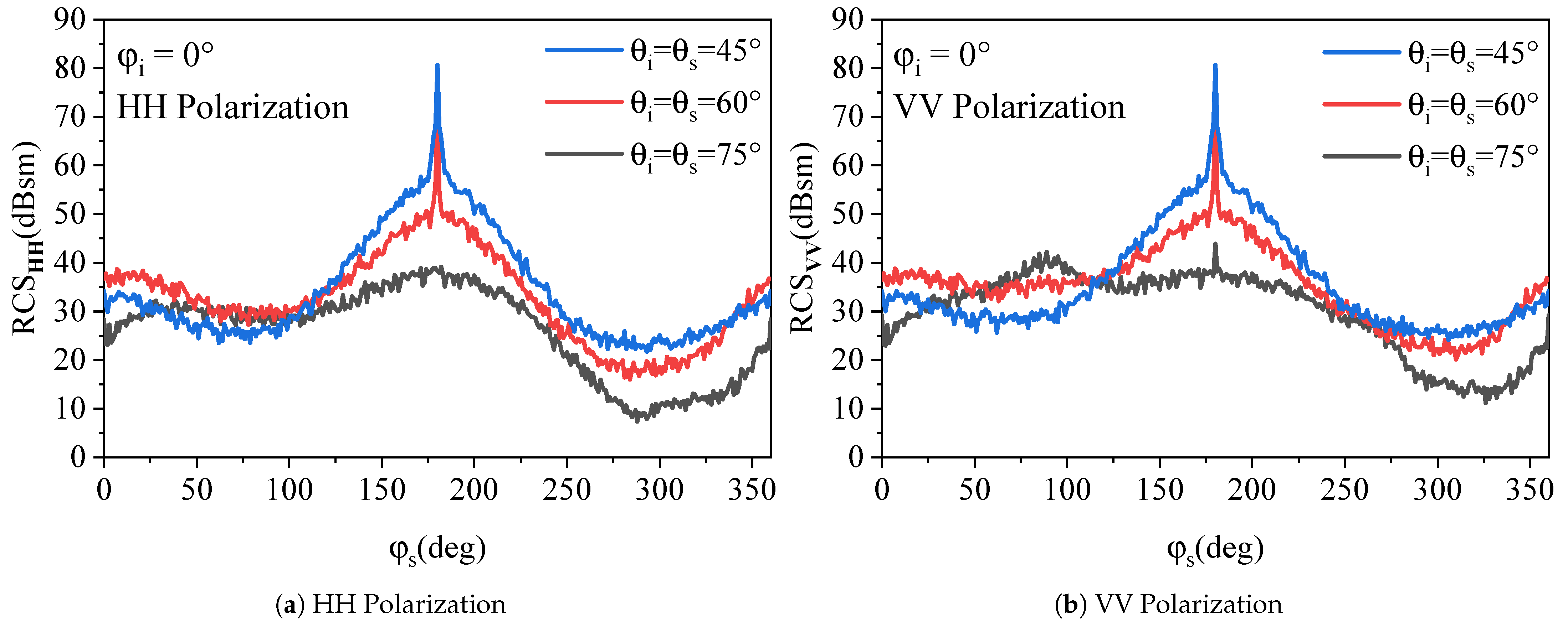
To characterize the azimuthal variation of the bistatic scattering response, the bistatic RCS are simulated with the incident azimuth angle fixed at φ i = 0 , while the scattering azimuth angle φ s is scanned over the full 360 range. Three selected elevation-angle combinations, i.e., θ i = θ s = 45 , 60 , and 75 , are considered. The corresponding azimuthal bistatic scattering responses for HH and VV polarizations are shown in Figure 11.
As shown in Figure 11, the HH- and VV-polarized responses exhibit similar overall azimuthal variation patterns, with the dominant scattering feature being centered around the forward/specular direction at φ s = 180 . For the cases of θ i = θ s = 45 and 60 , a pronounced narrow peak is observed near φ s = 180 , indicating that the coherent contribution remains significant under moderate elevation angles. Away from this direction, the scattering responses decrease gradually and evolve into a relatively smooth diffuse background, which can be mainly attributed to the combined contributions of vegetation volume scattering, rough-surface scattering, and canopy–ground interaction.
As shown in Figure 11, the HH- and VV-polarized scattering profiles exhibit pronounced symmetry and similar azimuthal variation patterns. For moderate elevation angles ( θ i = θ s = 45 and 60 ), a distinct and narrow coherent peak is firmly established near the exact forward scattering direction ( φ s = 180 ). This feature indicates that, under these geometries, the phase-matching condition is strongly satisfied, and the coherent forward-scattering mechanism remains highly dominant. Moving away from this specular region, the spatial energy smoothly redistributes into a relatively stable diffuse background. This non-specular floor primarily arises from the incoherent volume scattering within the canopy, the diffuse surface return, and the complex higher-order canopy–ground interactions.
As the elevation angle increases from 45 to 60 , both the peak magnitude near φ s = 180 and the surrounding azimuthal scattering levels decrease noticeably in the two polarizations. This trend suggests that the longer propagation path within the vegetation canopy at larger oblique angles enhances attenuation and scattering loss, thereby weakening both the coherent forward return and the associated diffuse interaction terms. For the grazing-angle case of θ i = θ s = 75 , the forward peak is still observable but becomes much less pronounced, while the overall azimuthal response is dominated by a lower and more oscillatory diffuse background. As shown in Figure 11, for the grazing-angle case of θ i = θ s = 75 , this behavior indicates that the coherent component is strongly suppressed due to the combined effects of stronger canopy extinction, surface shadowing/masking, and phase decorrelation among multiple scattering paths.
Overall, the azimuthal bistatic results show a clear transition from a scattering regime with a pronounced forward/specular component at moderate elevation angles to a regime dominated by weaker diffuse scattering at large oblique angles. The similar trends observed in HH and VV polarizations further indicate that the proposed VRT-S-BR framework is capable of describing the main three-dimensional scattering characteristics of vegetated rough surfaces under different azimuthal observation conditions.

4. Conclusions

This paper proposed a hybrid VRT-S-BR method for modeling composite electromagnetic scattering from targets above vegetation-covered rough surfaces. In the proposed framework, the vegetation layer is represented as a stratified medium and characterized using the VRT-S model in an offline manner. The resulting angle-dependent complex reflection coefficients are then incorporated into the BR formulation to replace the conventional Fresnel reflection terms, thereby accounting for vegetation-induced attenuation and coherent scattering effects. In addition, a deterministic facet-dependent phase compensation scheme is introduced to describe propagation-path variations of individual rays through the vegetation canopy, providing a more physically consistent treatment of target–vegetation coupling than empirical random phase perturbation models.
The proposed method was validated using field-measured backscattering data acquired over natural grassland, showing satisfactory agreement with RMSE values of 1.82 dB and 3.10 dB for HH and VV polarizations, respectively. Numerical results further demonstrated that vegetation coverage, vegetation height, terrain type, and bistatic observation geometry all have significant effects on the composite and coupled-scattering responses. In particular, the coupled-scattering RCS exhibits a nonlinear dependence on vegetation coverage, while the bistatic response shows a clear transition from coherent specular/forward scattering at moderate incidence angles to weaker diffuse scattering under grazing-angle conditions. These results indicate that the proposed VRT-S-BR method provides an efficient and physically interpretable tool for analyzing target scattering in vegetation-covered environments.

Author Contributions

Writing—original draft preparation, Y.-F.Z. and S.-R.C.; methodology, Y.-F.Z. and L.-X.G.; investigation, X.-J.Q., J.-J.L. and K.C.; validation, Y.-F.Z., L.-X.G. and W.L. All authors have read and agreed to the published version of the manuscript.

Funding

This work was supported in part by the Stable-Support Scientific Project of China Research Institute of Radiowave Propagation (Grant No. A240304170), and in part by the National Natural Science Foundation of China (Grant No. 62471361).

Data Availability Statement

The raw data supporting the conclusions of this article will be made available by the authors upon request.

Conflicts of Interest

The authors declare no conflicts of interest.

References

  1. Dubois, P.C.; van Zyl, J.; Engman, T. Measuring Soil Moisture with Imaging Radars. IEEE Trans. Geosci. Remote Sens. 1995, 33, 915–926. [Google Scholar] [CrossRef]
  2. Notarnicola, C.; Angiulli, M.; Posa, F. Use of Radar and Optical Remotely Sensed Data for Soil Moisture Retrieval over Vegetated Areas. IEEE Trans. Geosci. Remote Sens. 2006, 44, 925–935. [Google Scholar] [CrossRef]
  3. Entekhabi, D.; Njoku, E.G.; O’Neill, P.E.; Kellogg, K.H.; Crow, W.T.; Edelstein, W.N.; Entin, J.K.; Goodman, S.D.; Jackson, T.J.; Johnson, J.; et al. The Soil Moisture Active Passive (SMAP) Mission. Proc. IEEE 2010, 98, 704–716. [Google Scholar] [CrossRef]
  4. Moghaddam, M.; Saatchi, S.S. Monitoring Tree Moisture Using an Estimation Algorithm Applied to SAR Data from BOREAS. IEEE Trans. Geosci. Remote Sens. 1999, 37, 901–916. [Google Scholar] [CrossRef]
  5. Oh, Y.; Hong, J.-Y. Moment Method/Monte Carlo Simulation of the Microwave Backscatter of Wet-Land Rice Fields. In Proceedings of the IEEE International Geoscience and Remote Sensing Symposium (IGARSS), Barcelona, Spain, 23–28 July 2007; pp. 69–72. [Google Scholar] [CrossRef]
  6. Gu, W.; Tsang, L.; Colliander, A.; Yueh, S. Hybrid Method for Full-Wave Simulations of Forests at L-Band. IEEE Access 2022, 10, 105898–105909. [Google Scholar] [CrossRef]
  7. Jeong, J.; Tsang, L.; Colliander, A.; Yueh, S. Full-Wave Electromagnetic Simulations of Forests at L-Band by Using Fast Hybrid Method. Prog. Electromagn. Res. 2023, 178, 111–127. [Google Scholar]
  8. Liao, D.; Dogaru, T. Full-Wave Scattering and Imaging Characterization of Realistic Trees for FOPEN Sensing. IEEE Geosci. Remote Sens. Lett. 2016, 13, 957–961. [Google Scholar] [CrossRef]
  9. Jeong, J.; Tsang, L.; Kurum, M.; Ghosh, A.; Colliander, A.; Yueh, S.; McDonald, K.; Steiner, N.; Cosh, M.H. Full-Wave Simulations of Forest at L-Band with Fast Hybrid Multiple Scattering Theory Method and Comparison with GNSS Signals. IEEE J. Sel. Top. Appl. Earth Obs. Remote Sens. 2025, 18, 5395–5405. [Google Scholar] [CrossRef]
  10. Liao, T.H.; Kim, S.B.; Tan, S.; Tsang, L.; Su, C.; Jackson, T.J. Multiple Scattering Effects with Cyclical Correction in Active Remote Sensing of Vegetated Surface Using Vector Radiative Transfer Theory. IEEE J. Sel. Top. Appl. Earth Observ. Remote Sens. 2016, 9, 1414–1429. [Google Scholar] [CrossRef]
  11. Chen, K.; Tan, S. An Efficient Multiple Scattering Solution to Radiative Transfer Equations in Strong Forward Scattering Environments for Vegetated Land Emission and Its Representation Through an Equivalent Albedo-Tau Formalism. IEEE Trans. Geosci. Remote Sens. 2024, 62, 4401015. [Google Scholar] [CrossRef]
  12. Ulaby, F.T.; McDonald, K.; Sarabandi, K.; Dobson, M.C. Michigan Microwave Canopy Scattering Models (MIMICS). In Proceedings of the IEEE International Geoscience and Remote Sensing Symposium (IGARSS), Edinburgh, UK, 13–16 September 1988; Volume 2, p. 1009. [Google Scholar] [CrossRef]
  13. Ulaby, F.T.; Sarabandi, K.; McDonald, K.; Whitt, M.; Dobson, M.C. Michigan Microwave Canopy Scattering Model. Int. J. Remote Sens. 1990, 11, 1223–1253. [Google Scholar] [CrossRef]
  14. Karam, M.A.; Fung, A.K.; Lang, R.H.; Chauhan, N.S. A Microwave Scattering Model for Layered Vegetation. IEEE Trans. Geosci. Remote Sens. 1992, 30, 767–784. [Google Scholar] [CrossRef]
  15. Karam, M.A.; Fung, A.K.; Antar, Y.M.M. Electromagnetic Wave Scattering from Some Vegetation Samples. IEEE Trans. Geosci. Remote Sens. 1988, 26, 799–808. [Google Scholar] [CrossRef]
  16. Fung, A.K.; Li, Z.; Chen, K.S. Backscattering from a Randomly Rough Dielectric Surface. IEEE Trans. Geosci. Remote Sens. 1992, 30, 356–369. [Google Scholar] [CrossRef]
  17. Richards, J.A.; Sun, G.-Q.; Simonett, D.S. L-Band Radar Backscatter Modeling of Forest Stands. IEEE Trans. Geosci. Remote Sens. 1987, GE-25, 487–498. [Google Scholar] [CrossRef]
  18. Durden, S.L.; van Zyl, J.J.; Zebker, H.A. Modeling and Observation of the Radar Polarization Signature of Forested Areas. IEEE Trans. Geosci. Remote Sens. 1989, 27, 290–301. [Google Scholar] [CrossRef]
  19. Chauhan, N.S.; Lang, R.H.; Ranson, K.J. Radar Modeling of a Boreal Forest. IEEE Trans. Geosci. Remote Sens. 1991, 29, 627–638. [Google Scholar] [CrossRef]
  20. Saatchi, S.S.; McDonald, K.C. Coherent Effects in Microwave Backscattering Models for Forest Canopies. IEEE Trans. Geosci. Remote Sens. 1997, 35, 1032–1044. [Google Scholar] [CrossRef]
  21. Lin, Y.-C.; Sarabandi, K. A Monte Carlo Coherent Scattering Model for Forest Canopies Using Fractal-Generated Trees. IEEE Trans. Geosci. Remote Sens. 1999, 37, 440–451. [Google Scholar] [CrossRef]
  22. Chiu, T.; Sarabandi, K. Electromagnetic Scattering from Short Branching Vegetation. IEEE Trans. Geosci. Remote Sens. 2000, 38, 911–925. [Google Scholar] [CrossRef]
  23. Thirion, L.; Blanc-Colin, E.; Titin-Schnaider, C. A Coherent Scattering Model for a Tree: Validation and Applications. IEEE Trans. Geosci. Remote Sens. 2004, 42, 1729–1739. [Google Scholar]
  24. Attema, E.P.W.; Ulaby, F.T. Vegetation Modeled as a Water Cloud. Radio Sci. 1978, 13, 357–364. [Google Scholar] [CrossRef]
  25. Liu, C.; Shi, J. Estimation of Vegetation Parameters of Water Cloud Model for Global Soil Moisture Retrieval Using Time-Series L-Band Aquarius Observations. IEEE J. Sel. Top. Appl. Earth Obs. Remote Sens. 2016, 9, 5621–5633. [Google Scholar] [CrossRef]
  26. Wigneron, J.-P.; Kerr, Y.; Waldteufel, P.; Saleh, K.; Escorihuela, M.-J.; Richaume, P.; Ferrazzoli, P.; de Rosnay, P.; Gurney, R.; Calvet, J.-C.; et al. L-Band Microwave Emission of the Biosphere (L-MEB) Model: Description and Calibration Against Experimental Data Sets Over Crop Fields. Remote Sens. Environ. 2007, 107, 639–655. [Google Scholar] [CrossRef]
  27. Kurum, M.; Lang, R.H.; O’Neill, P.E.; Joseph, A.T.; Jackson, T.J.; Cosh, M.H. A First-Order Radiative Transfer Model for Microwave Radiometry of Forest Canopies at L-Band. IEEE Trans. Geosci. Remote Sens. 2011, 49, 3167–3179. [Google Scholar] [CrossRef]
  28. Fan, T.Q.; Guo, L.X.; Lv, B.; Liu, W. An Improved Backward SBR-PO/PTD Hybrid Method for the Backward Scattering Prediction of an Electrically Large Target. IEEE Antennas Wirel. Propag. Lett. 2016, 15, 512–515. [Google Scholar] [CrossRef]
  29. Ling, H.; Chou, R.-C.; Lee, S.-W. Shooting and Bouncing Rays: Calculating the RCS of an Arbitrarily Shaped Cavity. IEEE Trans. Antennas Propag. 1989, 37, 194–205. [Google Scholar] [CrossRef] [PubMed]
  30. Meng, X.; Wei, Q.H.; Dong, C.L.; Guo, L.X.; Chen, Y. A Composite Scattering Model of the Vegetated Ground with a Target. IEEE Antennas Wirel. Propag. Lett. 2023, 22, 1587–1591. [Google Scholar] [CrossRef]
  31. Tsang, L.; Kong, J.A.; Shin, R.T. Theory of Microwave Remote Sensing; Wiley: New York, NY, USA, 1985. [Google Scholar]
  32. Huang, H.; Tsang, L.; Njoku, E.G.; Colliander, A.; Liao, T.-H.; Ding, K.-H. Propagation and Scattering by a Layer of Randomly Distributed Dielectric Cylinders Using Monte Carlo Simulations of 3D Maxwell Equations with Applications in Microwave Interactions with Vegetation. IEEE Access 2017, 5, 11985–12003. [Google Scholar] [CrossRef]
  33. Jeong, J.; Tsang, L.; Gu, W.; Colliander, A.; Yueh, S.H. Wave Propagation in Vegetation Field by Combining Fast Multiple Scattering Theory and Numerical Electromagnetics in a Hybrid Method. IEEE Trans. Antennas Propag. 2023, 71, 3598–3610. [Google Scholar] [CrossRef]
  34. Toure, A.; Thomson, K.P.B.; Edwards, G.; Brown, R.J.; Brisco, B.G. Adaptation of the MIMICS Backscattering Model to the Agricultural Context-Wheat and Canola at L and C Bands. IEEE Trans. Geosci. Remote Sens. 1994, 32, 47–61. [Google Scholar] [CrossRef]
  35. Huang, B.; Chen, Y.; He, L.; Tong, L.; Wang, Y. Backscattering Modeling of Wheat Using Vector Radiative Transfer Theory. J. Appl. Remote Sens. 2015, 9, 097093. [Google Scholar] [CrossRef]
  36. Dong, C.; Guo, L.; Meng, X.; Li, H. An Improved GO-PO/PTD Hybrid Method for EM Scattering from Electrically Large Complex Targets. IEEE Trans. Antennas Propag. 2022, 70, 12130–12138. [Google Scholar] [CrossRef]
  37. Huang, W.-F.; Zhao, Z.; Zhao, R.; Wang, J.-Y.; Nie, Z.; Liu, Q.H. GO/PO and PTD with Virtual Divergence Factor for Fast Analysis of Scattering from Concave Complex Targets. IEEE Trans. Antennas Propag. 2015, 63, 2170–2179. [Google Scholar] [CrossRef]
  38. Yang, W.; Kee, C.Y.; Wang, C.-F. Novel Extension of SBR-PO Method for Solving Electrically Large and Complex Electromagnetic Scattering Problem in Half-Space. IEEE Trans. Geosci. Remote Sens. 2017, 55, 3931–3940. [Google Scholar] [CrossRef]
  39. Niknam, K.; Judge, J.; Roberts, A.K.; Monsivais-Huertero, A.; Moore, R.C.; Sarabandi, K.; Wu, J. A 3-D Full-Wave Model to Study the Impact of Soybean Components and Structure on L-Band Backscatter. IEEE J. Sel. Top. Appl. Earth Obs. Remote Sens. 2024, 17, 13089–13107. [Google Scholar] [CrossRef]
  40. Zeng, J.; Chen, K.-S.; Bi, H.; Zhao, T.; Yang, X. A Comprehensive Analysis of Rough Soil Surface Scattering and Emission Predicted by AIEM with Comparison to Numerical Simulations and Experimental Measurements. IEEE Trans. Geosci. Remote Sens. 2017, 55, 1696–1708. [Google Scholar] [CrossRef]
Figure 1. Kd-tree space partitioning for ray tracing acceleration.
Remotesensing 18 02183 g001
Figure 2. Schematic diagram of the VRT-S-BR hybrid method.
Remotesensing 18 02183 g002
Figure 3. Geometry of the layered vegetation structure.
Remotesensing 18 02183 g003
Figure 4. Photo illustration of the field measurement setup.
Remotesensing 18 02183 g004
Figure 5. Comparison between VRT-S-BR results and measured data for (a) HH polarization and (b) VV polarization.
Remotesensing 18 02183 g005
Figure 6. Backscattering RCS of a vegetated ground with a missile-shaped target model positioned 10 m above it.
Remotesensing 18 02183 g006
Figure 7. Comparison of RCS with varying vegetation cover rates: (a) Total RCS, and (b) Coupled RCS.
Remotesensing 18 02183 g007
Figure 8. Difference-field RCS of a missile-shaped target model above different ground surfaces.
Remotesensing 18 02183 g008
Figure 9. RCS comparison chart of different vegetation heights.
Remotesensing 18 02183 g009
Figure 10. Comparison of dual-station measurements at different incident angles.
Remotesensing 18 02183 g010
Figure 11. Comparison of bistatic measurements at different azimuth angles.
Remotesensing 18 02183 g011
Table 1. Ground-Related Parameters.
ParameterStemLeafGround
Moisture0.72 (g/g)0.67 (g/g)0.17 (g/cm3)
Height/Length50 cm120 mmRMS 1: 0.03 m
Width/RadiusRadius: 1 mmWidth: 10 mmCL 2: 0.3 m
Density320/m33430/m3
DistributionVerticalUniformUniform
1 RMS: Root Mean Square Height. 2 CL: Correlation Length.
Table 2. Vegetation Parameters for Different percentages of vegetation cover.
Parameter0% Vegetation Coverage50% Vegetation Coverage100% Vegetation Coverage
Stem moisture0.72 (g/g)0.72 (g/g)
Leaf moisture0.67 (g/g)0.67 (g/g)
Stem height50 cm50 cm
Leaf length120 mm120 mm
Stem radius1 mm1 mm
Leaf width10 mm10 mm
Stem density0160/m3320/m3
Leaf density01715/m33430/m3
Stem distributionVerticalVertical
Leaf distributionUniformUniform
Ground moisture0.17 (g/cm3)0.17 (g/cm3)0.17 (g/cm3)
Ground RMS 1 (m)0.030.030.03
Ground CL 2 (m)0.30.30.3
Ground distributionUniformUniformUniform
1 RMS: Root Mean Square Height. 2 CL: Correlation Length.
Table 3. Ground Surface Parameters.
ParameterVegetated GroundSnowy TerrainDesertBare Soil
RMS 1 (m)0.030.010.0150.02
CL 2 (m)0.30.050.0520.1
CRP 3, ε r 4.8 j 0.9 1.6 j 0.001 2.6 j 0.05 8.0 j 1.5
Area 10   m × 10   m 10   m × 10   m 10   m × 10   m 10   m × 10   m
1 RMS: Root Mean Square. 2 CL: Correlation Length. 3 CRP: Complex Relative Permittivity, ε r = ε j ε .
Table 4. Vegetation Parameters for Different Plant Heights.
ParameterVegetation Sample 1Vegetation Sample 2Vegetation Sample 3
Plant height (m)0.20.40.6
RMS 1 (m)0.030.030.03
CL 2 (m)0.30.30.3
Area 10   m × 10   m 10   m × 10   m 10   m × 10   m
1 RMS: Root Mean Square. 2 CL: Correlation Length.
Disclaimer/Publisher’s Note: The statements, opinions and data contained in all publications are solely those of the individual author(s) and contributor(s) and not of MDPI and/or the editor(s). MDPI and/or the editor(s) disclaim responsibility for any injury to people or property resulting from any ideas, methods, instructions or products referred to in the content.