Article

Nonlinear Stepped-Frequency MIMO PMCW Radar Systems with High Range Resolution Under Low Sampling Rates


1
Department of Electrical and Electronics Engineering, College of ICT Engineering, Chung-Ang University, Dongjak-gu, Seoul 06974, Republic of Korea
2
Department of Electrical and Computer Engineering and the Institute of New Media and Communications (INMC), Seoul National University (SNU), Gwanak-gu, Seoul 08826, Republic of Korea
*
Author to whom correspondence should be addressed.
Remote Sens. 2026, 18(10), 1576; https://doi.org/10.3390/rs18101576
Submission received: 8 April 2026 / Revised: 11 May 2026 / Accepted: 12 May 2026 / Published: 14 May 2026

Highlights

What are the main findings?
  • A nonlinear stepped-frequency (NSF) waveform is introduced for multiple-input multiple-output phase-modulated continuous wave radar systems. The proposed waveform enables high range resolution while maintaining a low analog-to-digital converter sampling rate, and adopts a block-based frequency-hopping structure that differs from conventional linear SF approaches.
  • To enable accurate high-resolution range estimation for the proposed waveform, a dedicated signal processing method is developed to handle nonlinear frequency variation.
What are the implications of the main findings?
  • The proposed system achieves range resolution comparable to a 3 GHz wideband radar using only 500 MHz bandwidth, which significantly reduces hardware complexity and sampling requirements.
  • The integration of NSF modulation with tailored signal processing improves robustness to interference and provides greater flexibility in waveform design. This makes the approach suitable for practical high-resolution radar applications.

Abstract

Phase-modulated continuous-wave (PMCW) radar systems are gaining interest for autonomous sensing. However, high range resolution typically demands prohibitively high sampling rates and computational loads. To address this issue, we propose a novel nonlinear stepped-frequency PMCW (NSF-PMCW) radar system. The proposed NSF-PMCW radar system periodically transmits sequences whose carrier frequency varies nonlinearly over time, and the associated signal processing method synthesizes a wide effective bandwidth by processing and coherently summing these frequency-varying sequences. This approach successfully enhances the range resolution without increasing the bandwidth and sampling rate of the analog-to-digital converter. Furthermore, we propose an angle estimation algorithm that accounts for the time-varying frequency of sequences to improve the estimation accuracy. The simulation results show that the proposed system can achieve the range resolution of a 3 GHz PMCW radar system while using only 500 MHz of bandwidth with a root mean square error of 0.0081 m in range estimation and 0 . 1114 in angle estimation.

1. Introduction

Radar systems have long been one of the most widely used sensors in remote sensing applications. Compared to optical or infrared sensors, radar systems offer a superior detection range with robustness against varying lighting conditions and weather [1], while also being capable of penetrating through clouds [2], vegetation [3], and even the ground surface [4]. These advantages have driven widespread adoption across diverse domains, such as automotive applications or environmental monitoring [5,6,7]. In these applications, a phase-modulated continuous wave (PMCW) radar system has attracted growing interest. It operates similarly to code division multiplexing, where the phase of a continuous-wave signal is modulated by a pseudorandom binary sequence (PRBS) designed to have good autocorrelation properties [8,9,10]. Because of the correlation property of the adopted PRBS, PMCW radar systems can obtain several advantages. First, PMCW radar systems can show a very sharp range profile, which can provide high target separability. Second, orthogonality between transmitting antenna elements can be easily achieved by assigning different binary sequences to each element. This allows all antenna elements to simultaneously transmit signals at the same time and frequency [11]. Finally, PMCW radar systems can achieve high robustness against interference and jamming, because the matched filter at the receiver produces a low cross-correlation response to signals that do not share the same PRBS [12,13].
However, PMCW radar systems require a significantly higher sampling rate compared to conventional radar systems such as frequency-modulated continuous wave radar systems, because the analog-to-digital converter (ADC) must operate at a sampling rate equivalent to the chip rate of the transmitted sequence [14,15,16,17]. Because the chip rate increases proportionally with bandwidth, a bandwidth of several gigahertz and a corresponding ADC sampling rate of several gigasamples per second are required for a range resolution of few centimeters. Furthermore, increasing the bandwidth reduces the unambiguous range for a given sequence length, and thus a longer binary sequence is required to maintain a sufficient unambiguous range. As a result, the radar system must process an enormous volume of signals within an extremely short time interval, which places a heavy computational burden on the hardware. To address this issue, stepped-frequency (SF) modulation has recently gained considerable research interest. In this approach, each signal occupies a narrow bandwidth, and the carrier frequency is incremented over multiple sequences to synthesize a wide effective bandwidth. This enables high range resolution without demanding a high ADC sampling rate, while also preserving a sufficient unambiguous range. Therefore, SF modulation has been extensively studied in radar systems [18,19,20,21], and its application to PMCW radar systems has also been explored.
The first study on SF-PMCW radar systems showed that linear SF (LSF) modulation introduces a range-Doppler coupling effect. Because of this range-Doppler coupling, targets at different ranges can be separated along the velocity axis with higher resolution. However, this does not improve the accuracy of the range estimation and it also increases the velocity estimation error [22]. The same authors proposed a waveform that simultaneously employs both upward and downward LSF modulation in a multiple-input multiple-output (MIMO) PMCW radar system [23]. In this approach, half of the total frame duration is allocated to upward stepping and the other half to downward stepping. Each half is processed separately to obtain a range-velocity map, and the range and velocity of each target are estimated from the detected peaks in each map. By averaging the velocity estimates from the two maps, the range-Doppler coupling is resolved, which allows more accurate range and velocity estimation. Then, a discrete Fourier transform (DFT) is applied along the virtual array element axis for angle estimation. However, this approach has several limitations. Because the total frame duration is divided into two halves, the coherent processing gain is reduced by half. This is because the two range-velocity maps cannot be coherently integrated, as the frequency stepping directions differ between them. Furthermore, the range and velocity estimation rely on peak matching between the two maps. In multi-target scenarios or low SNR conditions, the detected peaks in each map may not correspond to the same target, which can lead to mismatched pairing and erroneous estimation. In addition, existing studies on SF-PMCW radar systems have been limited to LSF modulation, and the adaptation of nonlinear SF (NSF) modulation in PMCW radar systems has not yet been investigated. Compared to LSF modulation, NSF modulation offers greater resistance to jamming and interception, because the unpredictable frequency pattern makes it significantly harder to detect. In addition, it can also enable flexible interference avoidance by skipping frequency bands that are corrupted by external interference. Although NSF modulation has been investigated in SF-orthogonal frequency division multiplexing (OFDM) radar systems [20,21], these approaches cannot be directly applied to PMCW-based systems due to fundamental differences in waveform structure and signal-processing framework. Therefore, the application of NSF modulation to PMCW radar systems remains an open research problem that has not yet been addressed in the literature. Table 1 summarizes the related works on stepped-frequency radar systems, categorized by waveform type, step pattern, and research objective.
Motivated by these advantages, this paper proposes, to the best of our knowledge, the first MIMO radar system that combines nonlinear stepped-frequency modulation with the PMCW waveform for high-resolution range estimation. Specifically, we propose a waveform design that enables high range resolution and coupling-free velocity estimation, along with a corresponding signal-processing method for range, velocity, and angle estimation. Through simulation, we demonstrate that the proposed waveform and signal processing method can achieve range resolution comparable to that of a 3 GHz PMCW radar system, even though the signal bandwidth is only 500 MHz, while a long maximum unambiguous range equivalent to that of a conventional 500 MHz PMCW system is maintained without any increase in sequence length. Furthermore, a performance comparison with LSF-PMCW radar systems shows that the transition to NSF modulation does not introduce any notable degradation in estimation accuracy. The contributions of this paper are as follows:
  • An NSF modulation for the MIMO PMCW radar system is proposed for the first time, which achieves high range resolution at a low ADC sampling rate.
  • To this end, a waveform design and signal processing method is proposed for an NSF-PMCW radar system that enables joint estimation of high-resolution range and coupling-free velocity.
  • An angle estimation method is also proposed for an NSF-PMCW MIMO radar system that accounts for the time-varying carrier frequency, which can achieve higher angle estimation accuracy than the DFT-based methods used in existing SF-PMCW radar studies.
The remainder of this paper is organized as follows. Section 2 describes the proposed waveform and a signal processing method for high-resolution sensing in an NSF-PMCW radar system. In Section 3, we evaluate the performance of the proposed method through simulations. We then discuss the results in Section 4. Finally, we conclude this paper in Section 5.

2. Materials and Methods

2.1. Conventional SF-PMCW Radar System

The signal model of the conventional SF-PMCW radar system can be expressed as
s CSF ( t ) = n = 0 N 1 p = 0 M P 1 ϕ [ n ] exp j 2 π ( f c + p M Δ f ) t rect t n T c p T T c ,
where ϕ [ n ] , n , p , · , rect ( · ) , T c , and T denote the n-th chip of the adopted PRBS, chip index, sequence index, floor operator, rectangular function, chip duration, and sequence duration, respectively. In addition, N , M , P , f c and Δ f denote the length of PRBS, number of sequence accumulations, number of effective sequences, initial carrier frequency, and frequency step size, respectively. The carrier frequency is stepped every M sequences, and the M sequences within each step are accumulated in the time domain at the receiver, which yields P effective sequences for velocity estimation. For range estimation, circular correlation along the chip axis between the received signal and PRBS is used, which can be expressed as
R CSF [ k , p ] = corr ( ϕ , y CSF [ n , p ] ) = n = 0 N 1 ϕ n k N y CSF [ n , p ] = R CSF [ k ] exp j 2 π Δ f τ + f d M T p exp j 2 π f d Δ f f c M T p 2 ,
where corr ( · ) , ( · ) , · , and y CSF , denote the correlation operation, complex conjugate, modulo operator, and the received signal after M sequence accumulation, respectively. In addition, R CSF [ k ] denotes the p-independent result of circular correlation between the received signal and the PRBS. Assuming ideal autocorrelation of the transmitted PRBS and zero Doppler frequency, the magnitude of R CSF is nonzero only at k target = 2 d c T c , where d is the range of the target, and it takes the value N, which can be expressed as
| R CSF [ k ] | = N , if k = k target ϵ k . if k k target
where ϵ k denotes the off-peak autocorrelation values of the PRBS sequence. The range resolution and the maximum unambiguous range are therefore c T c 2 and c T c N 2 , respectively. Then, subsequent velocity estimation is performed using DFT along the sequence axis, which can be expressed as
RD CSF [ k , q ] = p = 0 P 1 R CSF [ k , p ] exp j 2 π q p P = p = 0 P 1 R CSF [ k ] exp j 2 π Δ f τ + f d M T p exp j 2 π f d Δ f f c M T p 2 × exp j 2 π q p P = p = 0 P 1 R CSF [ k ] exp j 2 π Δ f τ + f d M T + q P p exp j 2 π f d Δ f f c M T p 2 ,
where τ and f d denote the time delay and Doppler frequency. By applying quadratic phase compensation [31], (4) can be further expressed as
RD CSF [ k , q ] R CSF [ k ] exp j π Δ f τ + f d M T + q P ( P 1 ) sin c P Δ f τ + f d M T + q P .
The magnitude of (5) along the velocity axis is maximized at a bin determined by the joint contribution of the time delay and the Doppler frequency, which is expressed as
q ^ = 2 f c M P T c v + 2 P Δ f c d ,
where · , c and v denote the round operator, speed of light and target’s velocity, respectively. As a result, targets that are not resolvable in the range axis can be separated along the velocity axis with a finer range resolution of c 2 P Δ f . This resolution enhancement is achieved without increasing the signal bandwidth, and a low ADC sampling rate can be maintained.

2.2. Problem Formulation

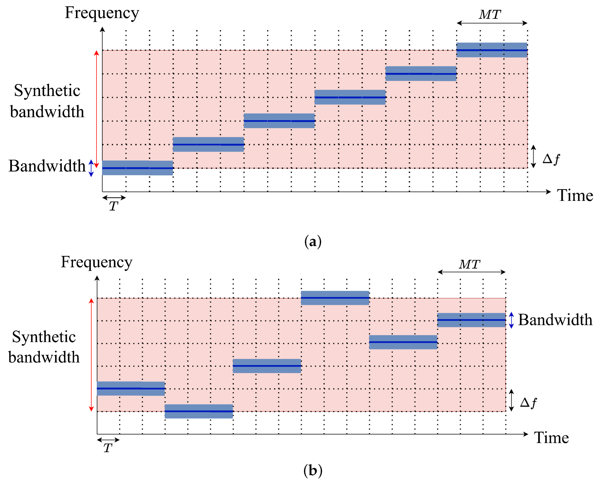
This section describes the problems that arise when NSF modulation is directly applied to the waveform proposed in LSF-PMCW studies in [22,23], in which the entire synthetic bandwidth is swept once over the full frame duration, as shown in Figure 1a. If the same approach is applied with a nonlinear hopping order, the resulting transmit waveform follows the pattern shown in Figure 1b. Then, the transmitted signal of the conventional waveform with NSF modulation pattern can be expressed as
RD CNSF [ k , q ] = p = 0 P 1 R CNSF [ k ] exp j 2 π f p τ + f d M T p exp j 2 π f d Δ f f c M T p 2 × exp j 2 π q p P = p = 0 P 1 R CNSF [ k ] exp j 2 π f d M T + q P p exp j 2 π f d Δ f f c M T p 2 × exp j 2 π f p τ ,
where f p denotes the pth carrier frequency in the nonlinear hopping order. In addition, R CNSF [ k ] denotes the p-independent result of circular correlation between the PMCW radar signal with NSF modulation in the conventional waveform and the PRBS.
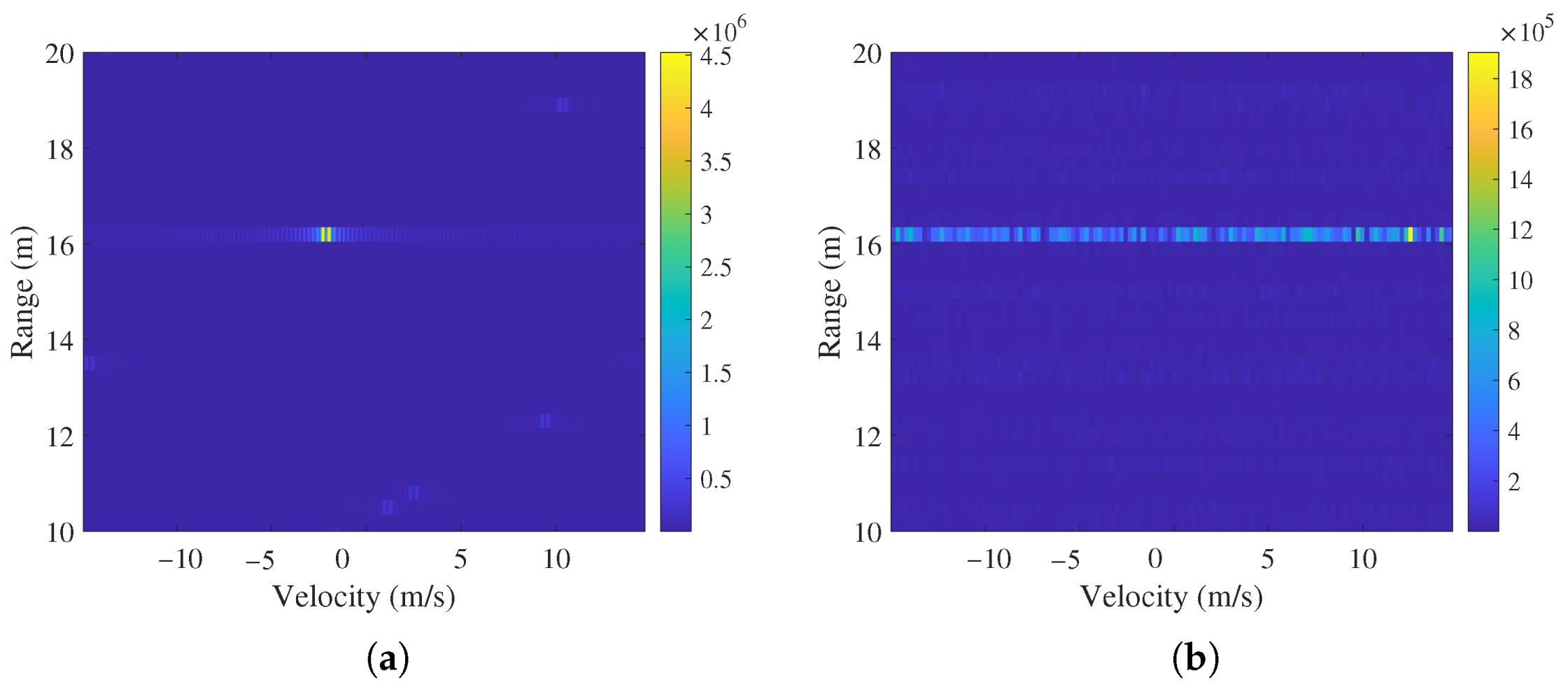
As shown in (7), the phase shift induced by the SF modulation is a nonlinear function of the sequence index p. This breaks the linear phase structure required for conventional LSF-PMCW processing. Consequently, both DFT-based velocity estimation and range resolution enhancement become infeasible. To demonstrate this limitation, the range-velocity maps obtained using the conventional linear SF scheme and the nonlinear SF scheme are compared in Figure 2. The scenario considers two targets with identical velocities and a small range separation that cannot be resolved with the conventional bandwidth. Figure 2a shows the result for the LSF-PMCW, where both targets are clearly observed. In contrast, when the waveform with NSF modulation is used, velocity estimation fails entirely, and the benefits of SF modulation are consequently lost. Therefore, a novel waveform design and a signal processing method are required for the NSF-PMCW radar system.

2.3. Proposed NSF-PMCW Radar System

2.3.1. Proposed Waveform for NSF-PMCW Radar System

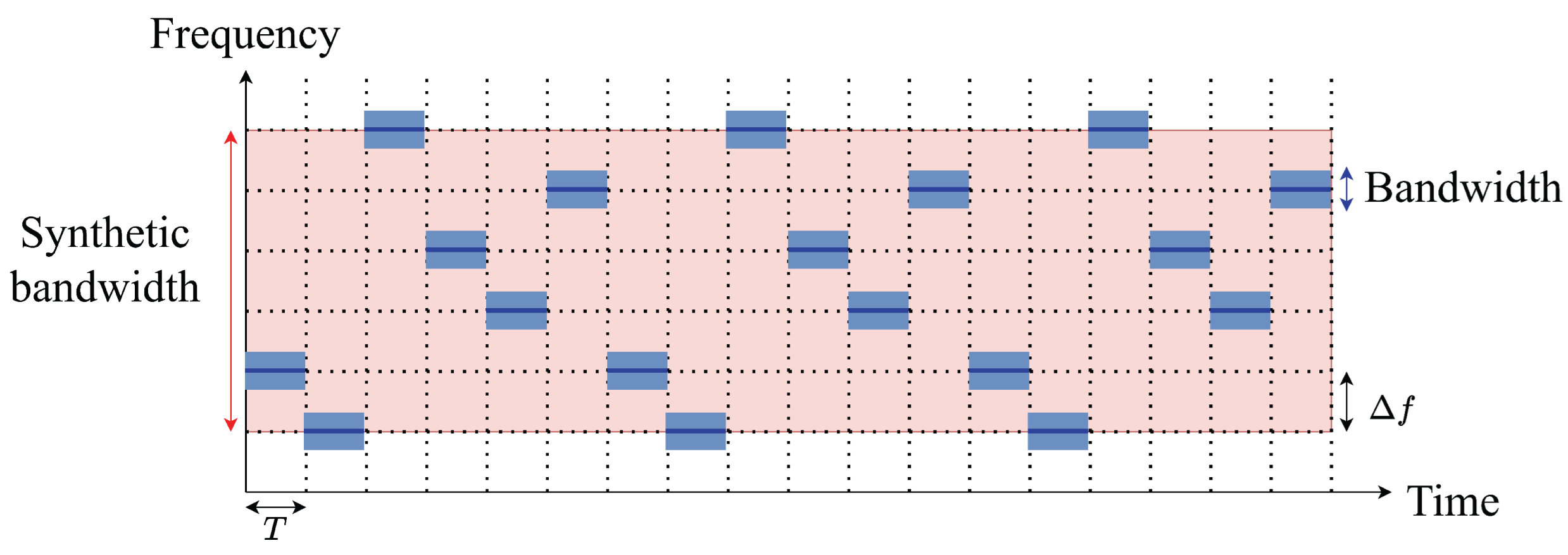
In this section, we propose a novel waveform design for improving range resolution in the NSF-PMCW radar system. The proposed waveform consists of P periodic transmissions of a sequence block containing M subsequences with carrier frequencies in a nonlinear order, as shown in Figure 3. Then, the transmitted signal can be expressed as
s ( t ) = n = 0 N 1 m NSF = 0 M 1 p NSF = 0 P 1 ϕ [ n ] rect t n T c ( p NSF M + m NSF ) T T c exp j 2 π ( f c + f m NSF ) t ,
where m NSF and p NSF denote subsequence index and sequence block index, respectively. In addition, the carrier frequency of m NSF -th subsequence in each sequence block can be expressed as
f m NSF = h [ m NSF ] Δ f ,
where h [ m NSF ] denotes the m NSF th element of the NSF hopping sequence, and the sequence { h [ 0 ] , h [ 1 ] , , h [ M 1 ] } is a permutation of { 0 , 1 , , M 1 } . When h [ m NSF ] = m NSF for all m NSF , the NSF modulation becomes identical to LSF modulation. The received signal after down conversion can be expressed as
y ( t ) = γ = 1 Γ n = 0 N 1 m NSF = 0 M 1 p NSF = 0 P 1 α γ ϕ n 2 d γ c T c rect t n T c ( p NSF M + m NSF ) T 2 d γ c T c × exp j 2 π f m NSF 2 d γ c exp j 2 π ( f c + f m NSF ) 2 v γ c t ,
where γ and α γ denote target index and attenuation factor, respectively. For notational simplicity, we omit scaling factors such as the attenuation factor and processing gain in the following. Then, the discrete signal after sampling can be expressed as
y [ n , m NSF , p NSF ] = γ = 1 Γ n = 0 N 1 m NSF = 0 M 1 p NSF = 0 P 1 α γ ϕ n 2 d γ c T c N exp j 2 π f m NSF 2 d γ c × exp j 2 π ( f c + f m NSF ) 2 v γ c ( n T s + ( p NSF M + m NSF ) T ) .
As shown above, the transmitted sequence appears at the receiver as a circularly shifted version due to the round-trip delay.

2.3.2. Generation of Range-Velocity Map

To estimate the range, circular correlation along the chip axis is performed between the discrete signal and the transmitted PRBS to form a range profile, which can be expressed as
R [ k , m NSF , p NSF ] = corr ( ϕ , y [ n , m NSF , p NSF ] ) = n = 0 N 1 ϕ n k N y [ n , m NSF , p NSF ] .
For velocity estimation, the discrete Fourier transform is applied along the sequence axis, which can be expressed as
RD [ k , m NSF , q ] = p NSF = 0 P 1 R [ k , m NSF , p NSF ] exp j 2 π q p NSF P .
The summation of (13) across all M frequency steps yields the initial range–velocity map, which can be expressed as
RDM [ k , q ] = m NSF = 0 M 1 RD [ k , m NSF , q ] .
In (14), the resolution for the range and velocity axes can be expressed as Δ d = c 2 B and Δ v = c 2 f eff P M T , where f eff = 1 M m = 0 M 1 f m NSF . Because the DFT is performed across sequences sharing the same carrier frequency, the range-Doppler coupling term and quadratic phase term are absent, and accurate velocity estimation is achievable. Next, a peak detection algorithm, such as constant false alarm rate, is carried out for target detection [32]. Let k γ and q γ denote the detected range and velocity bin indices for the γ -th detected target. Then, the estimated range and velocity of the target can be expressed as
d ^ γ = k γ c 2 B
and
v ^ γ = q γ c 2 f eff P M T ,
respectively.

2.3.3. Fine Range Estimation

After the detection of a target and its range and velocity bin ( k ^ γ , q ^ γ ) , the fine range estimation method is applied. The coarse range estimate d ^ γ obtained from the initial range-velocity map is limited by the range resolution c T c 2 , which is determined by the chip duration and the corresponding sampling rate. To refine this estimate, we exploit the phase information across the M frequency hops. These phases collectively form a synthetic bandwidth of M Δ f , which enables a finer range resolution of c 2 M Δ f . The signal vector of (13) with respect to the m-axis index can be expressed as
r k γ , q γ = RD [ k γ , 0 , q γ ] RD [ k γ , 1 , q γ ] RD [ k γ , M 1 , q γ ] = 1 exp j 2 π f 1 2 d γ c exp j 2 π f 1 2 v γ c T exp j 2 π f M 1 2 d γ c exp j 2 π f M 1 2 v γ c ( M 1 ) T .
To obtain only the range component resolved by synthetic bandwidth, we first compensate the phase using the estimated range and velocity, which can be expressed as
r comp , k γ , q γ [ m NSF ] = r k γ , q γ [ m NSF ] exp j 2 π f m NSF 2 v ^ γ c m NSF T × exp j 2 π Δ f 2 d ^ γ c h [ m NSF ] .
The phase compensation in (18) removes the velocity-induced phase shift and the coarse range-dependent phase component. As a result, the residual phase that corresponds solely to the unresolved range component d γ d ^ γ within each hop is isolated. The result of this compensation can be expressed as
r comp , k γ , q γ [ m NSF ] = 2 π Δ f 2 ( d d ^ γ ) c h [ m NSF ] .
This expression reveals that the residual range information is contained in the phase of each hop, and the phase varies across hops according to the permutation vector h . Because h represents a nonlinear frequency-hopping order, the phase response across the m NSF -axis forms a nonlinear pattern. Therefore, direct DFT-based processing cannot be applied straightforwardly. To address this, the samples must first be rearranged into a linear order.
By applying the permutation σ such that h [ σ ( m ) ] = m , the samples are reordered so that the phase response forms a linear ramp, which can be expressed as
r ˜ comp , k γ , q γ [ m ] = 2 π Δ f 2 ( d d ^ γ ) c m .
After reordering, the phase response forms a linear ramp with respect to m . This is equivalent to the signal model of a conventional stepped-frequency radar with a linear frequency order. Therefore, standard DFT processing can be applied, where the peak location in the resulting spectrum directly corresponds to the residual range d γ d ^ γ . As a result, the residual range can be estimated by applying DFT to (20), which can be expressed as
R fine [ k ] k γ , q γ = m = 0 M 1 r ˜ comp , k γ , q γ [ m ] exp j 2 π m k M ,
which is denoted as high-resolution range profile. The estimated residual range is obtained using a peak detection algorithm to (21). If we denote k γ as the index of the detected peak, the estimated residual range can be expressed as
d ^ res , γ = c 2 M Δ f k γ .
Finally, the fine range estimate can be calculated as
d ^ fine , γ = d ^ γ + d ^ res , γ ,
which reduces the quantization error of the initial range estimate with a resolution of c 2 M Δ f . This fine estimation stage not only enhances the accuracy in range estimation of individually detected targets, but also enables the resolution of multiple targets that were previously indistinguishable. Specifically, targets whose range difference is smaller than the range resolution c T c 2 appear as a single peak in the initial range-velocity map. If their range difference exceeds the fine range resolution c 2 M Δ f , however, they produce distinct peaks in the high-resolution range profile and can therefore be resolved individually.

2.3.4. Angle Estimation

In a MIMO PMCW radar system, orthogonality between transmitting antenna elements is achieved by assigning a distinct PRBS ϕ l Tx { 1 , + 1 } N to the l Tx -th transmitting antenna element, which allows the receiving antenna elements to separate the signals from each transmitting antenna element. Then, the received signal can be expressed as
y MIMO ( t ) = γ = 1 Γ l Tx = 0 L Tx 1 l Rx = 0 L Rx 1 n = 0 N 1 m NSF = 0 M 1 p NSF = 0 P 1 ϕ l Tx n 2 d γ c T c exp j 2 π ( f c + f m NSF ) t × exp j 2 π f m NSF ( l Tx d Tx + l Rx d Rx ) sin θ γ c exp j 2 π f m NSF 2 d γ c × exp j 2 π f m NSF 2 v γ c t rect t n T c ( p NSF M + m NSF ) T 2 d γ c T c ,
where L Tx , L Rx , l Rx , θ γ , d Tx and d Rx denote the number of transmitting antenna elements, number of receiving antenna elements, index of the virtual antenna element, angle of the γ -th target, antenna spacing between transmitting antenna elements, and antenna spacing between receiving antenna elements, respectively.
In conventional radar systems, angle estimation is performed by extracting the signal at the detected range-velocity bin along the virtual array element axis and applying algorithms such as DFT, Bartlett beamformer, or multiple signal classification (MUSIC) [33]. Following this approach, angle estimation in the proposed waveform can also be conducted after initial range-velocity detection and fine range estimation by extracting the signal at each detected peak along the virtual array element axis, where the signal vector along the virtual antenna axis at the ( k γ , q γ , k γ ) -th bin can be expressed as
a k γ , q γ , k γ [ l ] = exp j 2 π f m NSF l d ant sin θ γ c ,
where l denotes the virtual array element index defined as l = l Rx L Tx + l Tx , and d ant denotes the virtual antenna spacing. However, this approach leads to angle estimation errors. This is because the carrier-frequency variation across subsequences couples the spatial phase component with both the subsequence index and the virtual array element index. Furthermore, the time-varying carrier frequency across hops can no longer be compensated afterward, because the DFT along the subsequences axis is already applied for fine range estimation. As a result, applying conventional angle estimation methods leads to estimation errors.
To address this, we propose a method of steering vector formulation and an appropriate domain for angle estimation in the NSF-PMCW waveform. The key distinction is that angle estimation is performed using the M frequency bins prior to applying the DFT along the m NSF -axis, rather than after the DFT along the m NSF -axis as in conventional methods. Specifically, after applying the signal processing steps in Section 2.3.2 and Section 2.3.3 to obtain the fine range bin index k γ , the phase of (18) is re-compensated using k γ .
r ˜ k γ , q γ ( l ) [ m NSF ] = r comp , k γ , q γ ( l ) [ m NSF ] exp j 2 π Δ f 2 d ^ fine , γ c h [ m NSF ] ,
where d ^ fine , γ denotes the fine range corresponding to the detected peak index k γ . Then, the proposed steering vector a m NSF [ l , θ ] is defined per hop with the instantaneous carrier frequency f m NSF . This explicitly accounts for the time-varying carrier frequency across hops. The angle of the target is then estimated by applying an angle estimation algorithm. Any beamforming-based estimator, such as the Bartlett beamformer or MUSIC [34,35], can be applied within the proposed framework. In this work, the Bartlett beamformer is adopted as the underlying estimator, as it is the most widely used method in automotive radar applications owing to its low computational complexity. The angle of the target is estimated by finding the candidate angle that maximizes the pseudo-spectrum, which is expressed as
θ ^ γ = arg max θ m NSF = 0 M 1 l = 0 L 1 r ˜ k γ , q γ ( l ) [ m NSF ] a m NSF [ l , θ ] 2 ,
where a m NSF [ l , θ ] is expressed as
a m NSF [ l , θ ] = exp j 2 π f m NSF l d ant sin θ c .
It should be noted that (27) employs a compound steering vector that jointly accounts for both the fine range phase and the angle-dependent spatial phase, where the range component is pre-compensated in r ˜ and the angle component is represented in a m NSF [ l , θ ] . By compensating the phase of (18) with the fine range estimation result, the angle of each target can be estimated independently without any mapping ambiguity. The proposed angle estimation method in (27) is hereafter referred to as the proposed angle estimator (PAE).

3. Results

3.1. Simulation Parameter

The system parameters used in the simulation are shown in Table 2. The initial carrier frequency of 77 GHz is adopted, which is commonly used in automotive radar systems. In addition, the bandwidth is set to 500 MHz, which gives a range resolution of 0.3 m in the initial range estimation. To support a maximum unambiguous range of 300 m, the number of chips is set to 1023. To preserve the periodic autocorrelation property during the increment of the carrier frequency, two sequences are transmitted per carrier frequency, with one being discarded at the receiver. Therefore, the total number of transmitted sequences is equal to 2 M P = 8192 , and the number of sequence blocks and the number of subsequences processed at the receiver are 512 and 8, respectively. The frequency step size is set to 93.75 MHz, which results in a synthetic bandwidth of 3 GHz. This improves the range resolution of the system to 0.05 m when using the proposed method. Finally, Gold codes are employed for phase modulation.
For performance comparison, the proposed NSF-PMCW is evaluated against four systems: the narrowband PMCW system (NB-PMCW), the wideband PMCW system (WB-PMCW), the LSF-PMCW system (LSF-PMCW) in [22], and the linear upward and downward SF-PMCW system (LUDSF-PMCW) in [23]. All system parameters are similar to Table 2 except for the bandwidth. The NB-PMCW operates with a bandwidth of 500 MHz, which results in a range resolution of 0.3 m and a maximum unambiguous range of 300 m. For WB-PMCW, bandwidth is set to 3 GHz, which results in a range resolution of 0.05 m but a decreased maximum unambiguous range of 51 m. The bandwidth of both LSF-PMCW and LUDSF-PMCW is set to 500 MHz, with a frequency step size of 93.75 MHz and the number of effective sequences of 512. This results in a synthetic bandwidth of 3 GHz and a range resolution of 0.05 m. To ensure the same signal processing gain as the proposed NSF-PMCW in Table 2, NB-, WB-, LSF-, and LUDSF-PMCW use the correlator length of 1023, DFT size of 512, and sequence accumulation over every 8 sequences. This results in a theoretical signal processing gain of approximately 66.2 dB. The performance in range estimation is summarized in Table 3.

3.2. Results of Simulation

3.2.1. Performance in Target Separability

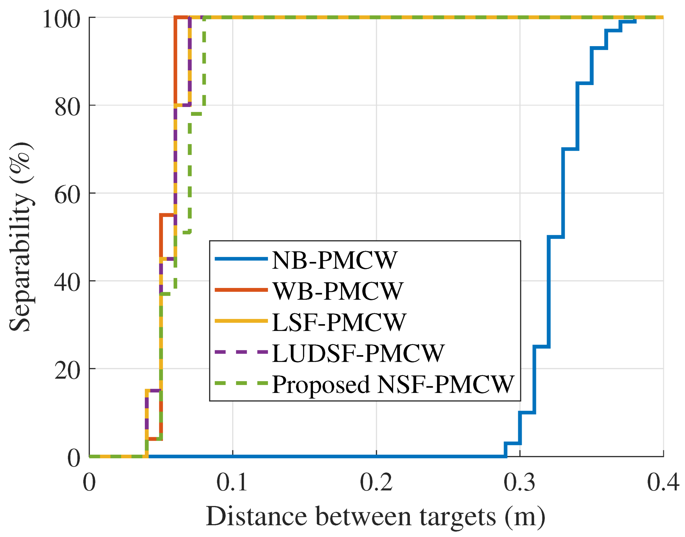
In this section, we compare the proposed NSF-PMCW radar system with the conventional PMCW radar systems shown in Table 3 in terms of target separability. Target separability is characterized by the probability of resolving two closely spaced targets as a function of their inter-target distance, following the Rayleigh resolution criterion. Specifically, the minimum resolvable distance is defined as the inter-target distance at which the resolution probability reaches 50% (median) and 90% across Monte Carlo trials, where each target is assigned an independent random initial phase uniformly distributed over [ 0 , 2 π ) . For each inter-target distance ranging from 0 m to 0.4 m with an interval of 0.01 m, N = 100 Monte Carlo trials are performed with randomized target phases, and the resolution probability is computed as the fraction of trials in which two distinct peaks are observed. The resulting resolution probability curve as a function of inter-target distance is used to extract the 50th- and 90th-percentile resolution distances.
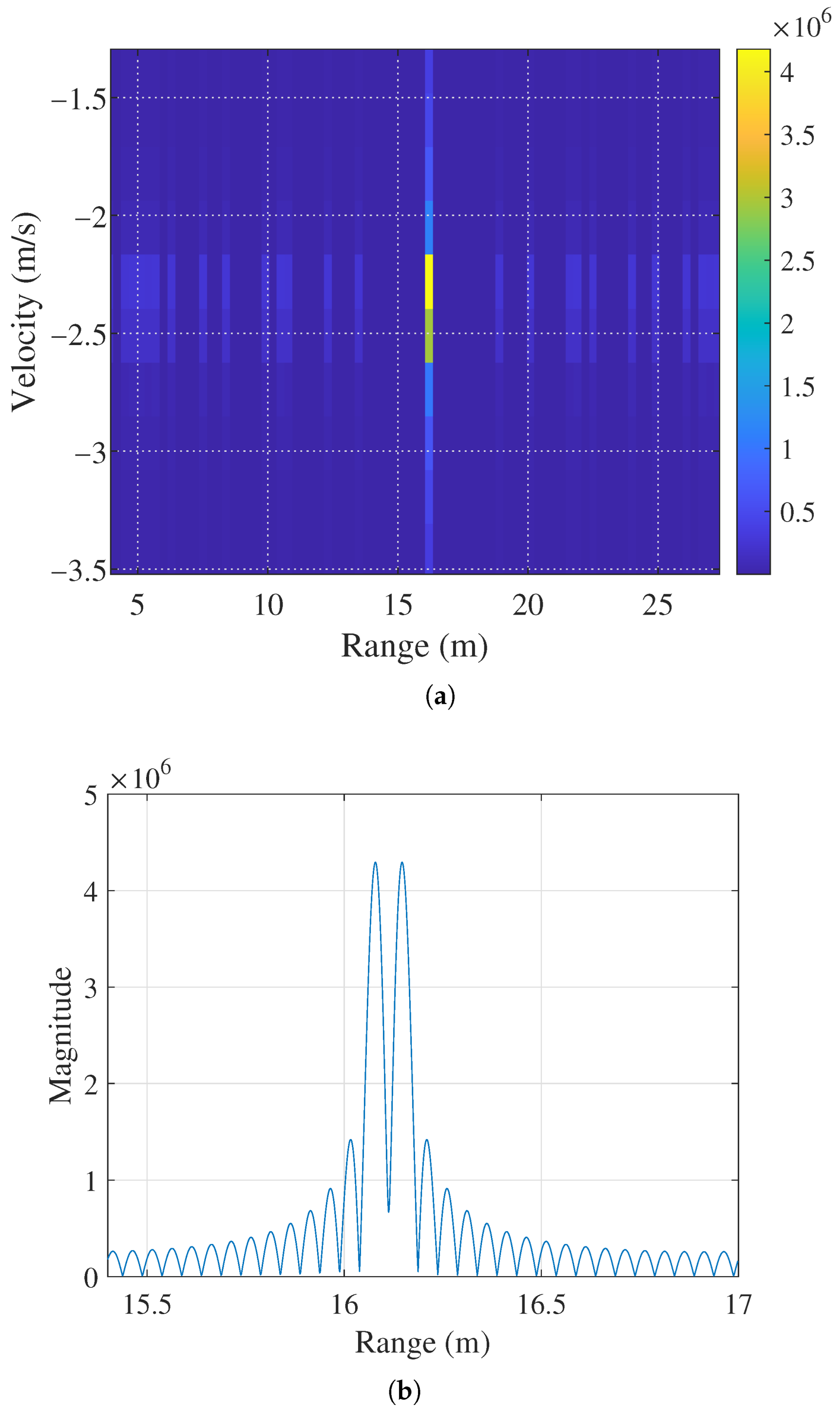
Figure 4 shows the range-velocity map and the high-resolution range profile of the proposed NSF-PMCW when the distance between targets is set to 0.06 m. As shown in the figure, two targets appear as a single peak in Figure 4a. However, two distinct peaks can be observed in the high-resolution range profile, which is shown in Figure 4b. This shows that the proposed method can resolve two closely spaced targets. The comparison of target separability is summarized in Figure 5. As shown in the figure, the NB-PMCW begins to resolve two distinct peaks only when the inter-target distance exceeds approximately 0.29 m. The 50th-percentile resolution distance is 0.325 m, and the 90th-percentile is 0.35 m, which closely aligns with its theoretical resolution of 0.3 m. In contrast, the WB-PMCW exhibits significantly improved separability. The 50th-percentile resolution distance is 0.05 m, and the 90th-percentile is 0.06 m, which is consistent with its theoretical range resolution of 0.05 m. The LSF-PMCW and the LUDSF-PMCW achieve a 50th-percentile resolution distance of 0.06 m and a 90th-percentile of 0.07 m, which is slightly inferior to the WB-PMCW. This is attributed to the differences in their frequency responses, where range migration causes targets to be resolved along the velocity axis and may aid in the separation of closely spaced targets. The proposed NSF-PMCW achieves a 50th-percentile resolution distance of 0.06 m, which is comparable to that of the LSF-PMCW and the LUDSF-PMCW and approaches the performance of the WB-PMCW. This confirms that the proposed NSF-PMCW achieves target separability close to that of the 3 GHz WB-PMCW system, even though it uses only 500 MHz of bandwidth.

3.2.2. Performance in Range and Angle Estimation

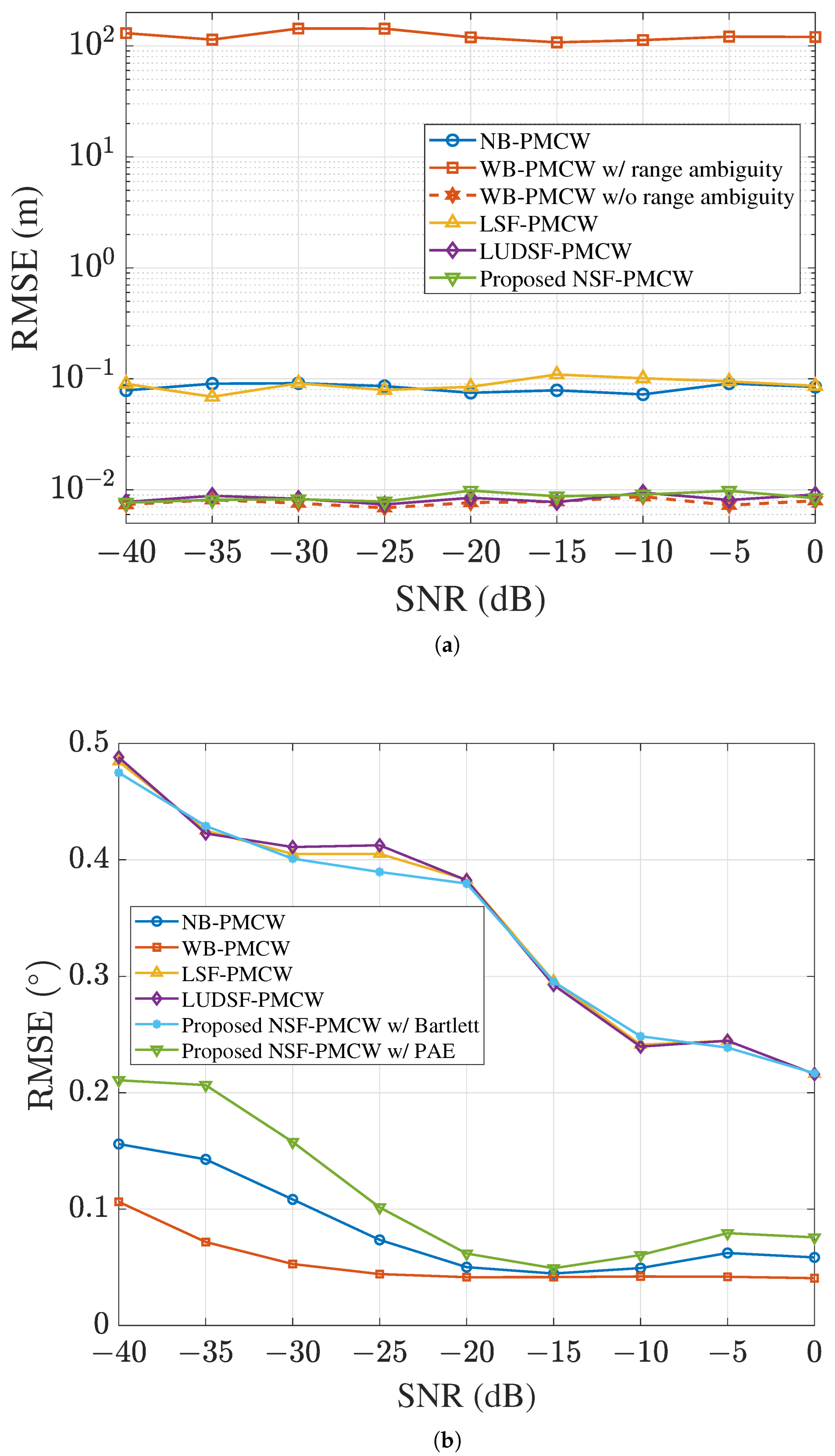
This section compares the performance of the proposed NSF-PMCW with other systems shown in Table 3 in terms of performance in range and angle estimation. The number of iterations for each signal-to-noise ratio (SNR) is set to 500, resulting in a total of 4500 simulations across the range from −40 dB to 0 dB with a 5 dB step. The number of targets is randomly selected from 1 to 10 in each iteration. The range, velocity, and angle of each target are set within [ 0 , 300 ] m, [ 40 , 40 ] m/s, and [ 90 , 90 ] , respectively. To consider off-grid scenarios, the range, velocity, and angle of each target are randomly initialized as continuous values, rather than being set to integer multiples of the system’s resolution. We first evaluate the range-estimation accuracy of each system.
Figure 6a shows the root mean square error (RMSE) in range estimation as a function of SNR. Among the compared methods, the NB-PMCW is free from range ambiguity throughout the entire 300 m target scenario; however, its coarse range resolution results in a relatively large mean error of 0.0832 m. The WB-PMCW, on the other hand, has high resolution but suffers from the shortest maximum unambiguous range of only 51 m under the same sequence-length condition. Consequently, while its mean error is as low as 0.0079 m in the ambiguity-free regime, the mean error rises sharply to 121.26 m once range ambiguity is taken into account. In the case of the LSF-PMCW, range migration caused by range-Doppler coupling yields target separability comparable to the WB-PMCW. However, the coupling itself cannot be resolved, and the range estimation accuracy remains as poor as that of the NB-PMCW, with a mean error of 0.0876 m. The LUDSF-PMCW resolves this range-Doppler coupling by processing upward and downward stepped-frequency waveforms separately. As expressed in (6), the range-dependent bias in the detected velocity bin appears with a positive sign for the upward waveform, while it appears with a negative sign for the downward waveform. Averaging the two estimates, therefore, can resolve the coupling, and the mean error is reduced to 0.0085 m. Finally, the proposed NSF-PMCW attains a mean estimation error of 0.0081 m. These results demonstrate that both the LUDSF-PMCW and the proposed NSF-PMCW achieve range resolution equivalent to that of the 3 GHz WB-PMCW system, while their extended maximum unambiguous range leads to superior overall estimation accuracy. Furthermore, the marginal difference in range estimation error between the linear and NSF-based systems confirms the effectiveness of the proposed waveform design and signal processing method.
We next evaluate the angle estimation accuracy of each system. All compared systems employ the Bartlett beamformer, which has the lowest computational complexity among high-resolution angle estimation algorithms. Although the study in [23] originally adopted a DFT-based angle estimation method, the Bartlett beamformer is also applied in this comparison due to its limited angular resolution. The proposed NSF-PMCW is evaluated under two configurations: one with the Bartlett beamformer and one with the PAE proposed in Section 2.3.4. All systems perform a grid search over the angular range of 90 to 90 with a step size of 0 . 1 . The MIMO array consists of 3 transmit and 4 receive antenna elements in a uniform linear array configuration along the azimuth direction, which yields a virtual array of 12 elements. The results are shown in Figure 6b. Both NB-PMCW and WB-PMCW demonstrate similar levels of accuracy, with only a negligible difference observed between them. While the WB-PMCW yields a slightly lower RMSE of 0 . 0536 compared to the 0 . 0831 of the NB-PMCW, their overall estimation trends are largely consistent. In contrast, the LSF-PMCW and LUDSF-PMCW exhibit large estimation errors, because the Bartlett beamformer does not account for the time-varying carrier frequency. The same issue arises in the proposed NSF-PMCW with the Bartlett beamformer. A similar performance degradation will occur with DFT-based angle estimation, where the coarse resolution will lead to even larger errors. However, when the PAE in Section 2.3.4 is applied instead, the mean error is reduced to 0 . 1114 , because the PAE accounts for the time-varying carrier frequency in the angle estimation process.

4. Discussion

Regarding velocity estimation performance, the proposed NSF-PMCW achieves the same theoretical velocity estimation accuracy as the conventional PMCW system when the sequence repetition interval is identical. In contrast, the LSF-PMCW and LUDSF-PMCW suffer from performance degradation in DFT-based velocity estimation due to the quadratic phase term, and alternative estimation methods are required. Therefore, in terms of DFT-based velocity estimation, the proposed NSF-PMCW radar system offers superior performance over the LSF-PMCW systems. One limitation of the proposed NSF-PMCW is the reduced flexibility in velocity estimation compared to the conventional PMCW and LSF-PMCW systems. In those systems, time-domain accumulation can be used to improve velocity resolution, while frequency-domain accumulation can be used to extend the maximum unambiguous velocity, which can provide greater flexibility in system design.
In the proposed NSF-PMCW, however, the sequence repetition interval is fixed at M N T c , which can improve velocity resolution but limits the maximum unambiguous velocity. This may be a disadvantage in applications that require a very high maximum unambiguous velocity. In practice, however, PMCW signals inherently have a very short chip period, which already results in a sufficiently high maximum unambiguous velocity from the outset, and this limitation is therefore unlikely to pose a significant problem in most practical applications. Regarding the time efficiency of each system, the conventional PMCW radar system requires only a single guard interval per frame, and the frame duration to achieve a processing gain of M N P can be expressed as
T frame PMCW = N ( M P + 1 ) T c .
The LUDSF-PMCW processes upward and downward stepped-frequency waveforms separately to resolve the range–Doppler coupling. However, because the peak position along the velocity axis differs between the two waveforms for the same target, integrating the two range–velocity maps either coherently or non-coherently is not applicable. Therefore, to achieve the target processing gain of M N P , the frame duration must be doubled compared to the conventional PMCW system, which can be expressed as
T frame UDSF - PMCW = 2 N ( M + 1 ) P T c .
Finally, the proposed NSF-PMCW requires a guard sequence at each frequency step to preserve the periodic correlation property of the PRBS, and one full sequence per step must therefore be reserved as a guard interval. Then, the frame duration required to achieve a processing gain of M N P is expressed as
T frame NSF - PMCW = 2 N M P T c .
As can be seen, the application of SF modulation requires additional guard sequences at each frequency transition, which reduces the time efficiency compared to the conventional PMCW radar system. Nevertheless, the proposed NSF-PMCW radar system achieves better time efficiency than the LUDSF-PMCW radar systems.

5. Conclusions

In this paper, we proposed a novel MIMO NSF-PMCW radar system that achieves high range resolution while maintaining a low ADC sampling rate and a wide unambiguous range. By designing a waveform where the carrier frequency hops nonlinearly across sequence blocks, we successfully integrated the advantages of NSF modulation into the PMCW radar systems. To resolve the challenges in parameter estimation caused by NSF modulation, we developed a comprehensive signal processing method, which includes a fine range estimation method and a PAE that accounts for time-varying carrier frequencies. The simulation results demonstrated that the proposed NSF-PMCW system achieves a range resolution of 0.05 m with only 500 MHz of instantaneous bandwidth, which is equivalent to the performance of a conventional 3 GHz wideband PMCW system. Furthermore, while conventional angle estimation methods suffer from errors due to SF modulation, the proposed PAE maintains accuracy with an RMSE of 0 . 1114 . We believe that the proposed NSF-PMCW radar system provides a robust and efficient solution for next-generation autonomous sensing applications, particularly in environments requiring high resolution and strong resistance to interference. For future work, experimental validation using actual hardware implementations will be necessary to further confirm the practical feasibility and real-world performance of the proposed system.

Author Contributions

Conceptualization, C.P. and S.L.; methodology, C.P.; software, C.P.; validation, C.P. and J.-H.P.; formal analysis, C.P. and J.-H.P.; investigation, C.P.; resources, S.L.; data curation, C.P.; writing—original draft preparation, C.P.; writing—review and editing, J.-H.P. and S.L.; visualization, C.P.; supervision, S.L.; project administration, S.L.; funding acquisition, S.L. All authors have read and agreed to the published version of the manuscript.

Funding

This work was supported in part by the National Research Foundation of Korea (NRF) grant funded by the Korea government (MSIT) (No. RS-2024-00405510) and in part by the Chung-Ang University Graduate Research Scholarship in 2025.

Institutional Review Board Statement

Not applicable.

Data Availability Statement

Restrictions apply to the datasets.

Conflicts of Interest

The authors declare no conflicts of interest.

Abbreviations

The following abbreviations are used in this manuscript:
ADCAnalog-to-digital converter
CFARConstant false alarm rate
DFTDiscrete Fourier transform
FMCWFrequency-modulated continuous wave
LSFLinear stepped-frequency
LUDSFLinear upward and downward stepped-frequency
MIMOMultiple-input multiple-output
NBNarrowband
NSFNonlinear stepped-frequency
OFDMOrthogonal frequency-division multiplexing
PAEProposed angle estimator
PMCWPhase-modulated continuous wave
PRBSPseudorandom binary sequence
RMSERoot mean square error
SFStepped-frequency
SNRSignal-to-noise ratio
WBWideband

References

  1. Bilik, I. Comparative analysis of radar and lidar technologies for automotive applications. IEEE Intell. Transp. Syst. Mag. 2023, 15, 244–269. [Google Scholar] [CrossRef]
  2. Moreira, A.; Prats-Iraola, P.; Younis, M.; Krieger, G.; Hajnsek, I.; Papathanassiou, K.P. A tutorial on synthetic aperture radar. IEEE Geosci. Remote Sens. Mag. 2013, 1, 6–43. [Google Scholar] [CrossRef]
  3. Steele-Dunne, S.C.; McNairn, H.; Monsivais-Huertero, A.; Judge, J.; Liu, P.-W.; Papathanassiou, K. Radar remote sensing of agricultural canopies: A review. IEEE J. Sel. Top. Appl. Earth Obs. Remote Sens. 2017, 10, 2249–2273. [Google Scholar] [CrossRef]
  4. Lu, Q.; Liu, C.; Wang, Y.; Liu, S.; Zeng, Z.; Feng, X.; She, S. Ground penetrating radar applications in mapping underground utilities. In Proceedings of the 2018 17th International Conference on Ground Penetrating Radar (GPR), Rapperswil, Switzerland, 18–21 June 2018; pp. 1–4. [Google Scholar]
  5. Ciattaglia, G.; De Santis, A.; Disha, D.; Spinsante, S.; Castellini, P.; Gambi, E. Performance evaluation of vibrational measurements through mmWave automotive radars. Remote Sens. 2021, 13, 98. [Google Scholar] [CrossRef]
  6. Liu, X.; Wang, Y.; Liu, F.; Zhang, Y. Investigation on the utilization of millimeter-wave radars for ocean wave monitoring. Remote Sens. 2023, 15, 5606. [Google Scholar] [CrossRef]
  7. Marković, I.; Yao, H.; Wielandt, S. A 60 GHz millimeter-wave FMCW radar system for real-time observations in remote outdoor environments. In Proceedings of the 2025 IEEE Sensors Applications Symposium (SAS), Newcastle, UK, 8–10 July 2025; pp. 1–5. [Google Scholar]
  8. Bourdoux, A.; Ahmad, U.; Guermandi, D.; Brebels, S.; Dewilde, A.; Van Thillo, W. PMCW waveform and MIMO technique for a 79 GHz CMOS automotive radar. In Proceedings of the 2016 IEEE Radar Conference (RadarConf), Philadelphia, PA, USA, 2–6 May 2016; pp. 1–5. [Google Scholar]
  9. Giroto de Oliveira, L.; Antes, T.; Nuss, B.; Bekker, E.; Bhutani, A.; Diewald, A.; Alabd, M.B.; Li, Y.; Pauli, M.; Zwick, T. Doppler shift tolerance of typical pseudorandom binary sequences in PMCW radar. Sensors 2022, 22, 3212. [Google Scholar] [CrossRef]
  10. Caffa, M.; Biletta, F.; Maggiora, R. Binary-phase vs. frequency modulated radar measured performances for automotive applications. Sensors 2023, 23, 5271. [Google Scholar] [CrossRef]
  11. Park, J.-H.; Ham, D.; Choi, J.; Lee, S.; Kim, S.-C. Compressive sensing-based demultiplexing of fast-time CDM-MIMO PMCW radar signals for self-code interference cancellation. IEEE Internet Things J. 2025, 12, 28060–28073. [Google Scholar] [CrossRef]
  12. Brown, M.C.; Li, C. Incorporation of digital modulation into vital sign detection and gesture recognition using multimode radar systems. Sensors 2023, 23, 7675. [Google Scholar] [CrossRef]
  13. Shang, X.; Lin, R.; Cheng, Y. Mixed-ADC based PMCW MIMO radar angle-Doppler imaging. IEEE Trans. Signal Process. 2024, 72, 883–895. [Google Scholar] [CrossRef]
  14. Wu, C.-Y.; Li, J.; Wong, T.F. Sparse parameter estimation for PMCW MIMO radar using few-bit ADCs. In Proceedings of the ICASSP 2021—2021 IEEE International Conference on Acoustics, Speech and Signal Processing (ICASSP), Toronto, ON, Canada, 6–11 June 2021; pp. 4415–4419. [Google Scholar]
  15. Cheng, Y.; Shang, X.; Liu, F. CRB analysis for mixed-ADC PMCW MIMO radar. In Proceedings of the 2021 CIE International Conference on Radar, Haikou, China, 15–19 December 2021; pp. 1032–1037. [Google Scholar]
  16. Wu, C.-Y.; Zhang, T.; Li, J.; Wong, T.F. Parameter estimation in PMCW MIMO radar systems with few-bit quantized observations. IEEE Trans. Signal Process. 2022, 70, 810–821. [Google Scholar] [CrossRef]
  17. Ren, J.; Wu, C.-Y.; Li, J.; Wong, T.F. High-speed moving target parameter estimation for one-bit MIMO PMCW automotive radar. In Proceedings of the 2023 57th Asilomar Conference on Signals, Systems, and Computers, Pacific Grove, CA, USA, 29 October–1 November 2023; pp. 1220–1224. [Google Scholar]
  18. Winkler, V. Novel waveform generation principle for short-range FMCW-radars. In Proceedings of the 2009 German Microwave Conference, Munich, Germany, 16–18 March 2009; pp. 1–4. [Google Scholar]
  19. Schweizer, B.; Knill, C.; Schindler, D.; Waldschmidt, C. Stepped-carrier OFDM-radar processing scheme to retrieve high-resolution range-velocity profile at low sampling rate. IEEE Trans. Microw. Theory Tech. 2018, 66, 1610–1618. [Google Scholar] [CrossRef]
  20. Yang, Y.; Kang, J.-S.; Park, J.; Guvenc, I.; Kim, H.; Jeong, B.J. Stepped-carrier OFDM with a nonlinear hopping pattern for joint radar and communications. IEEE Sens. J. 2022, 22, 24619–24633. [Google Scholar] [CrossRef]
  21. Tian, X. Range-Doppler processing of high-speed target in nonlinear stepped-carrier OFDM radar for automotive applications. IEEE Access 2025, 13, 163687–163698. [Google Scholar] [CrossRef]
  22. Kahlert, M.; Fei, T.; Tebruegge, C.; Gardill, M. Stepped-frequency PMCW-radar modulation scheme for automotive applications. In Proceedings of the 2024 IEEE Topical Conference on Wireless Sensors and Sensor Networks (WiSNeT), San Antonio, TX, USA, 21–24 January 2024; pp. 30–33. [Google Scholar]
  23. Kahlert, M.; Fei, T.; Tebruegge, C.; Gardill, M. Stepped-frequency PMCW waveforms for automotive radar applications. IEEE Trans. Radar Syst. 2025, 3, 233–245. [Google Scholar] [CrossRef]
  24. Su, H.; Balon, S.D.; Cheong, K.; Heng, C.H. A C-Band FMCW SAR transmitter based on synthetic bandwidth technique. IEEE Microw. Wirel. Compon. Lett. 2020, 31, 92–95. [Google Scholar] [CrossRef]
  25. Liu, X.; Maktoomi, M.H.; Alesheikh, M.; Heydari, P.; Aghasi, H. A CMOS 49–63-GHz phase-locked stepped-chirp FMCW radar transceiver. IEEE J. Solid-State Circuits 2025, 60, 4252–4266. [Google Scholar] [CrossRef]
  26. Zandieh, A.; Bonen, S.; Dadash, M.S.; Gong, M.J.; Hasch, J.; Voinigescu, S.P. 155 GHz FMCW and stepped-frequency carrier OFDM radar sensor transceiver IC featuring a PLL with <30 ns settling time and 40 fs rms jitter. IEEE Trans. Microw. Theory Tech. 2021, 69, 4908–4924. [Google Scholar] [CrossRef]
  27. Kang, J.-S.; Hong, Y.-K.; Jeon, J.-H.; Park, J.-H. Study on range-Doppler imaging using stepped-carrier OFDM waveforms with a nonlinear hopping pattern. J. Korean Inst. Electromagn. Eng. Sci. 2022, 33, 551–560. [Google Scholar] [CrossRef]
  28. Suh, J.; Gil, G.T.; Hong, S. Phase-discontinuity correction method with an overlapped signal structure in stepped-carrier OFDM radar with dual transmitters. IEEE Microw. Wirel. Compon. Lett. 2023, 33, 232–235. [Google Scholar] [CrossRef]
  29. Gil, G.T.; Suh, J.; Hong, S. Linear regression for phase discontinuity compensation in a stepped-carrier OFDM radar. IEEE Trans. Microw. Theory Tech. 2024, 72, 2019–2030. [Google Scholar] [CrossRef]
  30. Lee, K.I.; Shin, J.M.; Kim, D.I.; Choi, K.W. An experimental proof of concept for OFDM-based ISAC system utilizing stepped-carrier and TDM MIMO scheme. In Proceedings of the 2024 IEEE Signal Processing Advances in Wireless Communications (SPAWC), Lucca, Italy, 10–13 September 2024; pp. 1–5. [Google Scholar]
  31. Kahlert, M.; Fei, T.; Tebruegge, C.; Sun, S.; Gardill, M. Addressing speed-induced dispersion in stepped-frequency PMCW radar systems. In Proceedings of the ICASSP 2025—2025 IEEE International Conference on Acoustics, Speech and Signal Processing (ICASSP), Hyderabad, India, 6–11 April 2025; pp. 1–4. [Google Scholar]
  32. De Maio, A.; Aubry, A. Radar detection, performance analysis, and CFAR techniques. In Proceedings of the 2019 IEEE Radar Conference (RadarConf), Boston, MA, USA, 22–26 April 2019; pp. 1–120. [Google Scholar]
  33. Dhope, T.S.; Simunic, D. On the performance of AoA estimation algorithms in cognitive radio networks. In Proceedings of the 2012 International Conference on Communication, Information & Computing Technology (ICCICT), Mumbai, India, 19–20 October 2012; pp. 1–5. [Google Scholar]
  34. Van Trees, H.L. Optimum Array Processing; Wiley: New York, NY, USA, 2002. [Google Scholar]
  35. Schmidt, R.O. Multiple emitter location and signal parameter estimation. IEEE Trans. Antennas Propag. 1986, 34, 276–280. [Google Scholar] [CrossRef]
Figure 1. Diagram of conventional waveform: (a) conventional waveform with LSF modulation; (b) conventional waveform with NSF modulation.
Remotesensing 18 01576 g001
Figure 2. Range-velocity map with two targets with the same velocity but at different ranges: (a) range-velocity map of conventional SF-PMCW system with LSF modulation; (b) range-velocity map of conventional SF-PMCW system with NSF modulation.
Remotesensing 18 01576 g002
Figure 3. Diagram of the proposed waveform for the NSF-PMCW radar system.
Remotesensing 18 01576 g003
Figure 4. Target separability of the proposed NSF-PMCW when the distance between two targets is 0.06 m: (a) range-velocity map; (b) high-resolution range profile.
Remotesensing 18 01576 g004
Figure 5. Separability as a function of the distance between two targets for NB-PMCW, WB-PMCW, LSF-PMCW [22], LUDSF-PMCW [23], and the proposed NSF-PMCW.
Remotesensing 18 01576 g005
Figure 6. RMSE curves as a function of SNR for NB-PMCW, WB-PMCW, LSF-PMCW [22], LUDSF-PMCW [23], and the proposed NSF-PMCW: (a) range estimation and (b) angle estimation.
Remotesensing 18 01576 g006
Table 1. Summary of Related Works on Stepped-Frequency Radar Systems.
SystemAuthorStep PatternObjective
SF-FMCWWinkler [18]LinearFirst application of SF waveform to short-range automotive radar with reduced bandwidth
Su et al. [24]LinearSynthetic bandwidth generation via narrowband hardware
Liu et al. [25]LinearWideband transceiver design using dual phase-locked loop (PLL) architecture
SF-OFDMSchweizer et al. [19]LinearHigh-resolution range-velocity recovery at low sampling rate
Zandieh et al. [26]LinearFast-settling PLL design for high-speed frequency stepping
Kang et al. [27]NonlinearDoppler error compensation under nonlinear subband hopping
Yang et al. [20]NonlinearJoint radar-communication resource allocation
Suh et al. [28]LinearInter-subband phase discontinuity correction
Gil et al. [29]LinearReference-free real-time phase calibration
Lee et al. [30]LinearProof-of-concept ISAC implementation with MIMO capability
Tian et al. [21]NonlinearInter-carrier interference and velocity ambiguity mitigation for high-speed targets
SF-PMCWKahlert et al. [22]LinearAnalysis of LSF-PMCW radar system
Kahlert et al. [23]Up-DownUsage of LSF modulation with up and down pattern for range-velocity decoupling
Kahlert et al. [31]LinearDoppler dispersion suppression via quadratic phase compensation
Table 2. Parameters of the NSF-PMCW radar system used in the simulation.
ParameterValue
Initial carrier frequency, f c 77 GHz
Bandwidth, B500 MHz
Sampling rate, T c 2 ns
Number of chips, N1023
Number of sequence blocks, P512
Number of subsequences, M8
Frequency step size, Δ f 93.75 MHz
Synthetic bandwidth, M Δ f 3 GHz
Table 3. Specification of theoretical range estimation performance for each system.
SystemRange ResolutionMaximum Unambiguous Range
NB-PMCW0.3 m307 m
WB-PMCW0.05 m51 m
LSF-PMCW [22]0.05 m307 m
LUDSF-PMCW [23]0.05 m307 m
Proposed NSF-PMCW0.05 m307 m
Disclaimer/Publisher’s Note: The statements, opinions and data contained in all publications are solely those of the individual author(s) and contributor(s) and not of MDPI and/or the editor(s). MDPI and/or the editor(s) disclaim responsibility for any injury to people or property resulting from any ideas, methods, instructions or products referred to in the content.