Article

Adaptive Barrage Jamming Against SAR Based on Prior Information and Scene Segmentation

1
Henan Kaifeng College of Science Technology and Communication, Kaifeng 475000, China
2
Henan Engineering Research Center for AI Technology of Converged Media, Kaifeng 471699, China
3
Henan Engineering Research Center of Intelligent Technology and Application, Henan University, Kaifeng 475004, China
4
Henan Key Laboratory of Big Data Analysis and Processing, Henan University, Kaifeng 475004, China
5
College of Computer and Information Engineering, Henan University, Kaifeng 475004, China
6
College of Physics and Electronic Engineering, Northwest Normal University, Lanzhou 730070, China
*
Author to whom correspondence should be addressed.
Remote Sens. 2025, 17(7), 1303; https://doi.org/10.3390/rs17071303
Submission received: 10 March 2025 / Revised: 30 March 2025 / Accepted: 3 April 2025 / Published: 5 April 2025

Abstract

:
Due to the advantages of easy implementation and fine jamming effect, barrage jamming against synthetic aperture radar (SAR) has received extensive attention in the field of electronic countermeasures. However, most methods of barrage jamming still have limitations, such as uncontrollable jamming position and coverage and high-power requirements. To address these issues, an improved barrage jamming method is proposed in this paper. The proposed method fully combines the prior information of the region of interest (ROI), and the precise jamming with controllable position, coverage, and power is realized. For the proposed method, the ROI is firstly divided into several sub-scenes according to the obtained prior information, and the signal is intercepted. Then the frequency response function of the jammer for each sub-scene is generated. The frequency response function of the jammer, which consists of position modulation function and jamming coverage function, is decomposed into slow-time-dependent parts and slow-time-independent parts. The slow-time-independent parts are generated offline in advance, and the real-time performance of the proposed method is guaranteed through this way. Finally, the intercepted signal is modulated by the frequency response function to generate the two-dimensional controllable jamming effect. Theoretical analysis and simulation results show that the proposed method can produce jamming effects with controllable position and coverage, and the utilization efficiency of jamming power is improved.

1. Introduction

1.1. Background

As a type of high-resolution imaging radar, space-borne synthetic aperture radar (SAR) has the advantages of all-weather, all-day imaging, and certain penetration capabilities [1,2,3,4,5,6]. Thanks to these advantages, space-borne SAR has been widely applied in intelligence gathering, battlefield monitoring, and terminal guidance for missiles among numerous military fields, becoming a core sensor in modern warfare weapon systems [7]. To protect critical military targets and regional information, various jamming techniques targeting space-borne SAR are receiving increased attention [8,9,10]. Therefore, research on countermeasures against space-borne SAR holds significant military value.
Techniques or methods designed to disrupt or jam with SAR imaging are referred to as SAR jamming [11,12,13,14]. Generally, from the perspective of the jamming effect, SAR jamming techniques can be divided into two types: deceptive jamming and barrage jamming. Deceptive jamming involves implanting false scenes or false targets into SAR images, increasing the difficulty of identifying real targets [15,16,17]. However, deceptive jamming requires high levels of modulation precision and is challenging to implement [18]. Barrage jamming covers the real scene by transmitting or repeating high-power noise-like signals or partially coherent jamming signals. Compared to deceptive jamming, the implementation of barrage jamming is relatively easier, and the expected jamming effect can be achieved without complex modulation [19,20,21]. However, due to the two-dimensional matched filtering used in SAR imaging, barrage jamming typically demands higher transmission power [22].

1.2. Previous Work

Over the past few decades, various targeted jamming methods have been proposed to compensate for the insufficiency of traditional deceptive jamming and barrage jamming.

1.2.1. Deceptive Jamming

Research on deceptive jamming against SAR is mainly focused on scenes of deceptive jamming. In [23], the principle of deceptive jamming against SAR is introduced. In [24], deceptive jamming against SAR can be regarded as the convolution result of intercepted signals by the jammer and the response function of the jammer. Due to the complexity of time-domain convolution calculations, the implementation method usually involves performing a fast Fourier transform (FFT) on the signal intercepted by the jammer, multiplying it with the frequency response function of the jammer, and then performing an inverse fast Fourier transform (IFFT) to generate the jamming signal. Therefore, the main process of scene deceptive jamming against SAR is to construct the frequency response function of the jammer.
Currently, the problem with scene deceptive jamming focuses on the construction speed and the frequency response function of the jammer. To solve the computational burden of deceptive jamming, various studies have been conducted. In [25], the basic concept of the deceptive jamming method based on digital radio frequency memory (DRFM) is introduced. Sun et al. [26] proposed dividing the frequency response function of the jammer into two parts: slow-time-dependent and slow-time-independent. The slow-time-independent part can be calculated offline, which can effectively reduce the real-time computational burden of the jammer. Zhou et al. [27] proposed further reducing the computational burden and improving scenario realism by dividing the large scene template. On this basis, Yang et al. [28] proposed achieving azimuth jamming by shifting frequency in the azimuth direction, which further reduces the amount of jamming computation. In [29], a recursive algorithm is used to quickly generate deceptive jamming signals, and the computational complexity of jammers is further reduced.
Although the above-mentioned scene deceptive jamming methods have solved some of the computational burdens, they still need a lot of multiplication and summation operations in the real-time modulation phase when the deceptive scene coverage is large. Moreover, scene deceptive jamming methods have a high demand for modulation accuracy, and it is difficult to achieve ideal jamming effects in complex electronic warfare environments.

1.2.2. Barrage Jamming

As the most primitive jamming pattern in the field of electronic countermeasures, noise jamming has been widely used in engineering practice due to its low requirements for reconnaissance equipment and simple implementation [30,31]. There is no coherence between ordinary noise jamming and radar signals, the jamming signals cannot gain processing due to the non-matching filtering in the radar, which means that the jammer requires much higher power to effectively counter SAR [32].
Therefore, coherent barrage jamming targeting SAR has significant military significance and has received extensive attention from researchers. Based on this, researchers have conducted reverse research based on output requirements and obtained two types of jamming patterns, namely convolution modulation [33,34,35,36] and multiplication modulation [37,38,39], which have been applied to jamming detection and tracking radars. In terms of SAR jamming, Ye et al. [40] proposed a one-dimensional noise convolution jamming method for SAR. The method multiplies the intercepted signal at the range frequency domain with the frequency response function of the jammer directly generating barrage stripes along the range direction on the SAR image, and the jamming coverage determines the duration of the noise. On this basis, many researchers have conducted further research on convolution jamming. For example, the jamming effect of noise convolution is determined by the modulation function [41], two-dimensional convolution modulation [42], and the generation of dense false targets for barrage jamming by setting noise filtering thresholds [43]. In [44], a two-dimensional multiplication modulation jamming against SAR is proposed, where the jamming coverage is controlled by filtering the modulation template. Huang et al. [45] proposed a barrage jamming method based on range convolution and azimuth multiplication (RCAM), which controls the range position by fast time-frequency shift and the azimuth scope by slow time-domain filtering.
Compared to conventional noise jamming, coherent noise jamming can obtain processing gain in the radar, thereby reducing the requirements for the transmit power of the jammer. However, coherent noise jamming still has defects such as uncontrollable jamming position and coverage, and low gain when the jamming coverage is large. It is difficult to achieve the ideal cover effect in the scene while wasting power.

1.3. Main Contributions of This Paper

The scene prior information includes information such as the false target array position in the protection area, and the intercepted signal can be modulated by combining the prior information to generate the jamming at the specified position. Most of the current coherent noise jamming methods do not modulate the intercepted signal with prior information, but simply modulate the intercepted signal with a noise template and forward it. Therefore, the jamming generated by existing barrage jamming has the defects of uncontrollable position, coverage, and power, and the precise jamming to the protected area cannot be realized.
Therefore, it is worth considering how to apply prior information to the field of barrage jamming. Based on this, an adaptive barrage jamming method based on prior information and scene segmentation is proposed, which can achieve precise and controllable jamming coverage. The proposed method is divided into the following three units: information acquisition unit, position modulation unit, and jamming coverage unit. In the information acquisition unit, the information of the region of interest (ROI) is acquired in advance, and the ROI is divided into multiple sub-scenes. In addition, the reconnaissance equipment obtains the parameter information by analyzing the signal transmitted by the enemy SAR. In the position modulation unit and jamming coverage unit, the frequency response function of the jammer composed of the position modulation function and the jamming coverage function is generated, and the intercepted signal is modulated to generate the two-dimensional controllable jamming effect. The main contributions of this article are summarized as follows:
  • In this paper, scene prior information is fully combined with barrage jamming methods. The ROI is divided according to the acquired prior information. The jamming power is allocated according to the importance of different targets in the ROI. The utilization efficiency of jamming power is effectively improved in this way, and a better jamming effect can be achieved with limited jamming power.
  • In this paper, a frequency response function of a jammer, which is a two-step process integrating position modulation function with jamming coverage function, is proposed to jam targets in the SAR image. Important targets are better protected by generating corresponding response functions for different sub-scenes.
  • In this paper, the jamming gain and measurement of the proposed method are analyzed in detail. Then, the simulation experiment was carried out. Firstly, the point target and target simulation experiments of the traditional convolution jamming method are extended. Then, a simulation experiment is conducted using the method proposed in this paper. Simulation results show that the proposed method not only overcomes the limitations of uncontrollable jamming position and coverage of traditional jamming methods but also effectively improves the utilization efficiency of jamming power.

1.4. Organization of This Paper

The remainder of this article is organized as follows. In Section 2, the jamming model of space-borne SAR is introduced, the principle of noise convolution and noise multiplication jamming are reviewed, and a detailed description of the proposed method is provided. In Section 3, a theoretical analysis of the jamming signal is conducted, including an analysis of jamming gain and measurement error. In Section 4, the simulation results of our experiments are demonstrated, verifying the effectiveness of the proposed method. Section 5 discusses the proposed method. Section 6 provides the conclusion.

2. Model and Method

2.1. SAR Jamming Geometric Model

The section derives a geometric model and introduces the basic idea for space-borne SAR repeater jamming.
The geometric relationship of jamming in Stripmap SAR is shown in Figure 1. A X O Y coordinate system is established with O as the origin, where X and Y represent the azimuth and range directions, respectively. The jammer is located at the origin O . The shortest slant range between the SAR and the jammer is denoted as R 0 . The initial position of SAR is ( 0 , R 0 ) , and the SAR platform flies at a uniform velocity v along X . The antenna center points at the jammer at a slow time t a = 0 , and L a is the synthetic aperture length. ( x , y ) is the position of an arbitrary false point target in the ROI, where x and y represents the azimuth and range position, respectively. The instantaneous slant distance between the SAR and the jammer is expressed as R j t a . The instantaneous slant distance between the SAR and the ideal false target is expressed as R v t a .
As shown in Figure 1, the SAR platform transmits signals to the protected scene, and the jammer intercepts and measures the captured SAR signals to obtain the required parameter information. According to the response function of the jammer, the jammer modulates the intercepted SAR signal to generate the jamming signal. Subsequently, the generated jamming signal is forwarded along R j t a .
The received signal s e t by the SAR receiver can be expressed as follows:
s e t = s w t + I t ,
where s w t represents the echo of the SAR and I t represents the echo of the jamming.
Finally, the echo signal and jamming signal enter the two-dimensional matched filter of the SAR, resulting in jamming effects in the SAR image.
According to Figure 1, R j t a and R v t a can be expressed as follows:
R j t a = R 0 2 + v t a 2 ,
R v t a = R 0 + y 2 + x v t a 2 .
Based on the Taylor series expansion, R j t a and R v t a can be rewritten as
R j t a R 0 + v t a 2 2 R 0 ,
R v t a R 0 + y + x 2 2 R 0 + y x v t a R 0 + y + v t a 2 2 R 0 + y .
For the space-borne SAR, R 0 y , then rewrite (5) as follows:
R v t a R j t a + R t a ,
with
R t a = y + x 2 2 R 0 x v t a R 0 .
In order to generate jamming at a given position, we generate a slant range of a false point to simulate the slant range of the ideal point target R v t a by delaying the signal intercepted by the jammer. Therefore, by modulating the round-trip time delay 2 R t a of the intercepted signal, the jamming at the specified position can be generated to achieve the purpose of protecting our scene target.
The working mechanism of repeater-type jamming is based on “intercept-modulate-retransmit”, as shown in Figure 2. The jammer performs a series of operations on the intercepted SAR signal, including amplification, down-conversion, and analog-to-digital conversion (A/D), to obtain a digital baseband signal. The jammer modulates the digital baseband signal to generate jamming signals, which are then converted from digital to analog (D/A), up-converted, and subjected to gain control. The jamming signals are then retransmitted to the SAR, resulting in jamming effects in the SAR image.

2.2. Noise Convolution Jamming Principle

Noise convolution modulation jamming can obtain a certain processing gain during radar signal processing, thus greatly reducing the demand for jamming power [40].
In order to destroy the SAR system’s reconnaissance of important military installations and deployments, the jammer intercepts the signal and performs down-conversion processing to obtain the down-converted intercepted signal s i t r , t a .
Jamming signal m t r , t a is generated by convolution of intercepted signal and offline modulated noise template in the time domain. m t r , t a can be expressed as follows:
m t r , t a = s i t r , t a n t r ,
where represents the convolution operation in fast time, n ( t r ) is the one-dimensional white Gaussian noise template modulated offline, T n is the fast time width, and T n can be expressed as follows:
T n = 2 Y j c ,
where c represents the speed of light, and Y j is the range jamming length set by the jammer.
The jammer converts the modulated signal m t r , t a into jamming signal m j ( t r , t a ) through up-conversion processing and forwards the jamming signal to the radar. Finally, after radar imaging processing, the range direction lag jamming is generated in the SAR image.

2.3. Proposed Method

The proposed jamming method is devoted to achieving controllable jamming coverage in range and azimuth directions instead of well-focused false targets. The focus of the proposed method is to achieve flexible control of jamming and improve the utilization efficiency of jammer power. Based on this, defocus and convolution are used to cover the protection area, and the controllable jamming effect is achieved while ensuring high processing gain. In addition, by offline slow-time-independent part, the real-time modulation amount of the jammer is effectively reduced, and the real-time performance of the jamming is guaranteed.
According to the prior information obtained in advance and the expected jamming effect, the frequency response function of the jammer composed of the position modulation function and the jamming coverage function is generated, and the intercepted signal is modulated to generate the two-dimensional controllable jamming effect.
The flowchart of the proposed method is shown in Figure 3, which can be divided into the following three parts: information acquisition unit, position modulation unit, and jamming coverage unit.

2.3.1. Information Acquisition Unit

In this unit, the scene prior information and radar information are obtained in advance and utilized. The scene prior information includes the position information P ( x , y ) of the point target array in the scene to be protected and the importance of different targets in the protection scene. Radar information includes radar track direction, radar effective velocity v , carrier frequency f 0 , and the shortest slant distance R 0 between radar and jammer.
According to the pre-obtained scene information, the protected scene is jammed by modulating multiple jamming templates. As shown in Figure 4, according to the known prior information, the protected scene P x , y is divided to obtain n sub-scenes P i j x , y .
P x , y = i j P i j x , y .
The number of sub-scenes is directly related to the jamming effect and the amount of calculation. The larger the number of sub-scenes, the greater the gain of the jamming signal and the better the jamming effect, but the real-time calculation amount is also bigger currently. The proposed method uses noise convolution in the range direction and phase error in the azimuth direction to generate jamming coverage. The jamming of convolution modulation lags the jammer [40], and the defocus generated by quadratic phase error modulation covers the surroundings of the jammer [46]. Therefore, if jamming is performed on the sub-scene, the position of the jamming echo must be located in the starting range direction and the middle azimuth of the sub-scene. As shown in Figure 4, M i j is the jamming center position of the sub-scene P i j . The protection scene is segmented according to the prior information, and the jamming position array M i j ( x , y ) of multiple sub-scenes is obtained.
According to the importance of the sub-scenes and the total jamming power, the jamming power modulation coefficient ρ i j of each sub-scene can be obtained. The slow time-independent part of the frequency response function of the jammer is modulated offline according to the jamming position array M i j ( x , y ) , the size of the sub-scene, and the required power of the sub-scene.
In addition, the SAR signal in the ROI is intercepted by the jammer, the parameter information of the intercepted signal is obtained through the reconnaissance system, and the frequency down-conversion and FFT are performed on the intercepted signal at the same time so that the jammer can modulate it.
The radar transmission signal assumed to be a linear frequency modulation (LFM) signal can be expressed as
s t r = r e c t t r T p e x p j π k r t r 2 e x p j 2 π f 0 t r ,
where t r represents the fast time, T p represents the signal duration, and k r represents the range chirp rate.
The intercepted signal after down-conversion can be expressed as
s i t r , t a = s t r δ t r τ j t a e x p j 2 π f 0 t r   = r e c t t r τ j t a T p e x p j 2 π f 0 τ j t a e x p j π k r t r τ j t a 2 ,
where δ ( · ) represents the impulse function, τ j t a = R j t a c represents the one-way delay between the radar and the jammer. The jammer performs FFT on the intercepted signal s i ( t r , t a ) to obtain s i ( f r , t a ) .

2.3.2. Position Modulation Unit

In this unit, the frequency response function of position modulation H 1 ( f r , t a ) is generated by the jammer, and the position of the jamming can be controlled by H 1 ( f r , t a ) .
According to the jamming position array obtained by prior information, the scene positions of all point targets in the false point target array M i j ( x , y ) can be obtained. Without loss of generality, only single-point targets are considered here.
The position modulation function can be generated by delaying and forwarding the signal intercepted by the jammer. The baseband echo of the jammer s j t r , t a and the baseband echo of the ideal false target s v t r , t a can be expressed as
s j t r , t a = s t r δ t r 2 τ j t a e x p j 2 π f 0 t r = r e c t t r 2 τ j t a T p e x p j 4 π f 0 τ j t a e x p j π k r t r τ j t a 2 ,
s v t r , t a = s t r δ t r 2 τ v t a e x p j 2 π f 0 t r   = r e c t t r 2 τ v t a T p e x p j 4 π f 0 τ v t a e x p j π k r t r τ v t a 2 ,
where τ v t a = R v t a c represent the one-way delay between the SAR and the ideal false target.
Based on the principle of stationary phase (POSP), the range frequency domain form of s v t r , t a can be expressed as
s v f r , t a = s j f r , t a e x p j 2 π f r 2 R t a c · e x p j 2 π f 0 2 R t a c .
At this time, the frequency response function of position modulation H 1 f r , t a can be expressed as
H 1 f r , t a = e x p j 2 π f r + f 0 2 R t a c .
Speaking of substituting (7) into (16), (16) can be rewritten as
H 1 f r , t a = e x p j 2 π f 0 2 y c e x p j 2 π f 0 x 2 c R 0 e x p j 2 π f 0 2 x v t a c R 0 · e x p j 2 π f r 2 y c e x p j 2 π f r x 2 c R 0 e x p j 2 π f r 2 x v t a c R 0 ,
where the first and second exponential terms are independent of f r and t a , and are fixed phases independent of imaging. The first and second exponential terms can be regarded as residual RCM. The focus of the proposed method is to generate jamming coverage rather than well-focused false targets. To ensure real-time, some phase terms can be ignored. At this time, the frequency response function of position modulation H 1 ( f r , t a ) can be rewritten as
H 1 f r , t a = e x p j 2 π f r t r e x p j 2 π f t a ,
with
t r = 2 y c ,
f = K a x v = 2 f 0 x v t a c R 0 ,
where K a = 2 f 0 v 2 c R 0 represents the azimuth chirp rate, t r represents range position factor, and f represents the azimuth position factor.
The range direction position of the jamming coverage can be controlled by changing the range position factor t r , and the azimuth direction position can be controlled by changing the f azimuth position factor f .

2.3.3. Jamming Coverage Unit

In this unit, the frequency response function of jamming coverage H 2 ( f r , t a ) is generated by the jammer, and the jamming coverage can be controlled by H 2 ( f r , t a ) .
The noise template is modulated according to the sub-scene jamming power modulation coefficient ρ i j assigned to the sub-scene P i j x , y and the size of the sub-scene. Without loss of generality, only a single sub-scene noise template is considered.
In the range direction, the noise convolution method is used to generate jamming. Generate an initial noise template n i j t r with the range coverage factor of T n according to the segmentation of sub-scenes. n i j t r is transformed into a range frequency domain by FFT, and n i j f r is obtained.
In the azimuth direction, quadratic phase error modulation is used to generate jamming due to the azimuth chirp rate mismatch leading to the main lobe broadening.
After sub-scene power allocation, the frequency response function of noise modulation can be expressed as
H 2 f r , t a = ρ i j n i j f r e x p j π K a t a 2 ,
where K a = ε K a represent the azimuth coverage factor, and ε represents the azimuth jamming coverage coefficient.
The range direction coverage of the jamming can be controlled by changing the range coverage factor T n , and the azimuth direction coverage can be controlled by changing the azimuth jamming coverage coefficient ε .
For a single sub-scene, the frequency response function of the jammer is expressed as
H f r , t a = ρ i n i f r e x p j 2 π f r t r · e x p j 2 π f t a e x p j π K a t a 2 .
Due to the azimuth chirp rate error, the azimuth position factor f can be rewritten as
f = K a + K a x v = 2 x v t a c R 0 1 + ε .
In (22), the first exponential term depends only on the position offset between the jammer and the false point target array; while the second and third exponential terms heavily depend on the slow time t a ; the modulation of the noise template n i _ a f r , t a is related to the radar effective velocity v , the signal wavelength λ , and the shortest slant distance R 0 between the radar and the jammer.
According to the prior information obtained in advance, the first exponential term and the noise template can be generated in an offline mode. The jammer frequency response function can be expressed as
H f r , t a = x y F 1 x , y F 2 x , y ,
with
F 1 x , y = ρ i n i f r e x p j 2 π f r t r ,
F 2 x , y = e x p j π K a t a 2 e x p j 2 π f t a ,
where F 1 x , y is the slow-time-independent parts, and F 2 x , y is the slow-time-dependent parts.
Therefore, the frequency response function of the jammer can be generated in two steps: (1) generating F 1 x , y offline; (2) generating F 2 x , y in real-time.
The intercepted signal is modulated by the jammer frequency response function H f r , t a to generate the jamming signal, which is forwarded to SAR by the jammer. The adversary SAR processes the received jamming signal, and the SAR image containing jamming is generated.
The jamming method proposed in this paper has excellent real-time performance, and different jamming effects can be generated by modulating the corresponding frequency response functions of jammer modulating.

3. Signal Imaging Process and Analysis

Currently, there are many imaging algorithms used for processing SAR signals for different application scenarios, such as the range-Doppler algorithm (RDA), Chirp Scaling algorithm (CSA), ω K algorithm ( ω KA), etc. The RDA decomposes the echo into range and azimuth echoes and performs two-dimensional pulse compression through two matched filtering operations. Based on the simple and easy-to-analyze one-dimensional operation of the range-Doppler algorithm, this paper selects RDA as the jamming imaging algorithm.

3.1. Analysis of Jamming Gain

For traditional noise jamming, no signal processing gain can be obtained due to the lack of coherence with the radar signal. Therefore, traditional noise jamming requires a large amount of jamming power [32]. The traditional noise convolution modulation jamming can only obtain the range processing gain and cannot control the power distribution of the jamming in the azimuth direction. The jamming proposed in this paper can obtain the two-dimensional signal processing gain of the radar and reduce the demand for jamming power.
For illustration, the coupling between the range direction and the azimuth direction is ignored, only the fast time item is considered for further derivation and analysis in the range direction.
Based on the well-known POSP, after the SAR performs range compression on the received single baseband jamming echo, J r c t r can be represented as
J r c t r = n i a t r p s f t r ,
with
p s f t r = s i n c B r t r 2 R j t a c t r ,
where p s f t r represents the point spread function of the range echo component, and B r represents the range bandwidth of the SAR signal.
The range compressed results can be expressed as the convolution of the range noise template and the point spread function, indicating that the range gain of jamming mainly comes from the point spread function of the radar signal. This is also the theoretical basis for the reduction of jammer transmission power in noise convolution jamming.
Due to the large bandwidth of SAR, the s i n c · function can be approximated as a δ · function, so the jamming range compression result can be approximated as
J r c t r n t r 2 R j t a c t r .
The position-controllable jamming coverage with width p r = c T n 2 can be generated.
The pulse width of the jamming signal before compression is T p + T n . From (28), the pulse width of the compressed radar signal is 1 B r , therefore the pulse width of the compressed jamming signal is T n + 1 B r . Since the compression network is passive, the power before and after compression remains the same, which means that
J i T n + T p = J 0 T n + 1 / B r ,
where J i and J 0 represent the jamming power before and after range compression, respectively.
Therefore, the range gain can be expressed as
G r = J 0 J i = T n + T p T n + 1 / B r .
For a given SAR signal time duration and bandwidth, the range gain of the jamming directly depends on the fast-time width of the noise modulation template. When T n 1 B r , the jamming gain is approximately T p B r , meaning that the gain obtained by jamming is basically equal to the gain obtained by the target echo, and the power required for jamming is greatly reduced, but the coverage of jamming at this time is very small.
In the azimuth direction, only the slow time item is considered for further derivation and analysis. The azimuth jamming echo component can be expressed as
J a t a = r e c t t a T s e x p j π K a t a 2 e x p j 2 π f t a · e x p j π K a t a f / K a 2 .
where T s represents the width of the jamming signal before azimuth compression.
According to the POSP and the chirp rate error K a > 0 , the azimuth compression results J r a t r , t a can be represented as
J a c t a = p s f t a e x p j π t a f / K a 2 K a K a K a + K a ,
with
p s f t a = s i n c t a f / K a K a + K a / K a T s ,
where p s f t a represents the point spread function of the azimuth echo component, and T s represents the synthetic aperture time.
According to the envelope representation shown in (34), the position-controllable jamming coverage can be generated. The azimuth width p a of the jamming coverage can be calculated as
p a = v K a T s K a + K a .
where p a represents the width of the jamming signal after azimuth compression. Same as the range analysis method, the azimuth gain is expressed as
G a = K a + K a K a = 1 + K a K a .
For a given SAR signal, the azimuth gain of jamming is inversely proportional to the degree of mismatch in the azimuth chirp rate. The smaller the K a , the larger the jamming gain is, but the azimuth jamming coverage is very small at this time.
Therefore, the two-dimensional total gain G obtained by the proposed method is expressed as
G = G r G a .

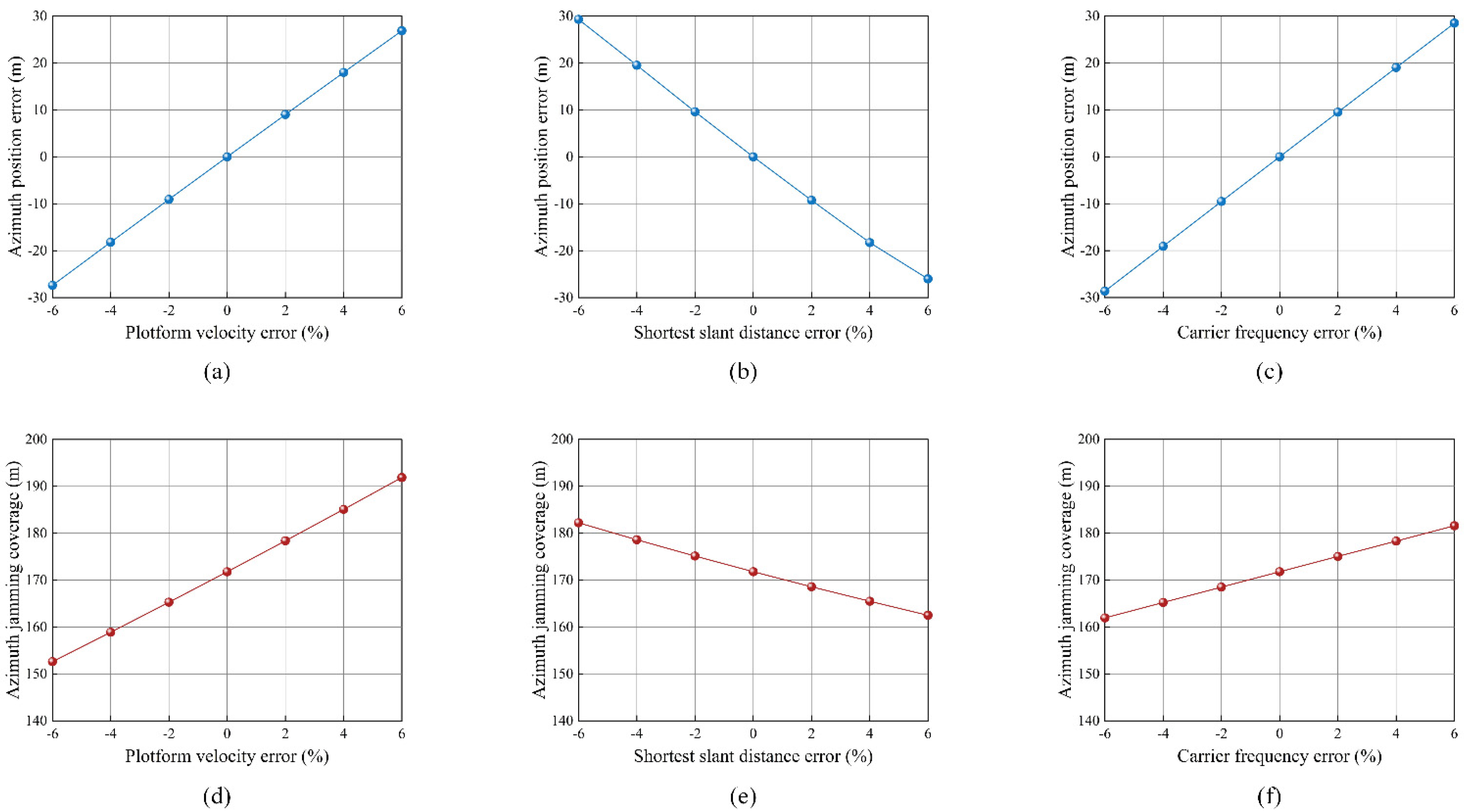
3.2. Analysis of Measurement Error

The proposed method requires reconnaissance equipment to pre-measure the motion parameters and waveform parameters of the enemy SAR, such as SAR platform velocity v , shortest slant distance R 0 , carrier frequency f 0 , etc. In actual situations, estimation errors from non-cooperative SAR platforms are inevitable, which will lead to errors in jamming position and coverage. The impact of parameter measurement errors on the proposed method is discussed in the following analysis.

3.2.1. Platform Velocity Error

First, the platform velocity error of the SAR platform is analyzed. The measured velocity under reconnaissance error is assumed to be v . The azimuth position factor f in the case of platform velocity error can be expressed as
f = 2 x v f 0 c R 0 1 + ε .
According to (29), one can conclude that measured velocity v has no effect on the range imaging.
With the modulated H f r , t a , the azimuth chirp rate can be expressed as
K a e = K a + K a = 2 f 0 c R 0 v 2 + ε v 2 ,
where K a and K a are caused by s j t r , t a and H f r , t a , respectively.
With the employment of (23), the azimuth position error x is given by
x = v f / K a e x = x v v 1 + ε v 2 + ε v 2 1 .
In this respect, the jamming coverage p a is given by
p a = v K a T s K a + K a = v K a T s K a v 2 / v 2 + K a .

3.2.2. Shortest Slant Distance Error

Next, we focus the effect of shortest slant distance error. The measured shortest slant distance under reconnaissance error is assumed to be R 0 . The azimuth position factor f in the case of shortest slant distance error can be expressed as
f = 2 x v f 0 c R 0 1 + ε .
Like the velocity error, the range imaging performance is not affected by the short slant distance error.
With the modulated H f r , t a , the azimuth chirp rate can be expressed as
K a e = K a + K a = 2 f 0 v 2 c 1 R 0 + ε R 0 .
According to (23), the azimuth position error x is given by
x = v f / K a e x = x R 0 1 + ε R 0 + ε R 0 1 .
Additionally, the jamming coverage error p a is given by
p a = v K a T s K a + K a = v K a T s K a R 0 / R 0 + K a .

3.2.3. Carrier Frequency Error

Finally, the carrier frequency error is analyzed to acquire a better jamming effect. The measured carrier frequency error under reconnaissance error is assumed to be f 0 . The azimuth position factor f in the case of carrier frequency error can be expressed as
f = 2 x v f 0 c R 0 1 + ε .
Similar to the above, the range imaging performance is not affected by the carrier frequency error.
With the modulated H f r , t a , the azimuth chirp rate can be expressed as
K a e = K a + K a = 2 v 2 c R 0 f 0 + ε f 0 .
Afterward, the azimuth position error x is given by
x = v f / K a e x = x f 0 1 + ε f 0 + ε f 0 1 .
Consequently, the jamming coverage p a is given by
p a = v K a T s K a + K a = v K a T s K a f 0 / f 0 + K a .
The impact caused by the above errors is quantitatively analyzed in Figure 5 according to the system parameters shown in Table 1. The azimuth offset x and range offset y between the jammer and the false target are set to x = 500   m and y = 500   m , respectively. It is worth noting that the range-direction imaging effect is almost unaffected by the above errors, and thus only the azimuth direction imaging is shown.
The influence of the reconnaissance error against the azimuth position is shown in Figure 5a–c. Additionally, Figure 5d–f show the change of the azimuth jamming coverage under the reconnaissance error. It can be seen that the reconnaissance error does not affect the output form of the jamming, but only causes the deviation between the actual jamming effect and the predetermined jamming effect. Therefore, the proposed method in this paper has low requirements for reconnaissance equipment.

4. Simulation and Results

In this section, point and area target simulations are carried out to demonstrate the effectiveness of the proposed method. The main parameters of the radar are listed in Table 1.

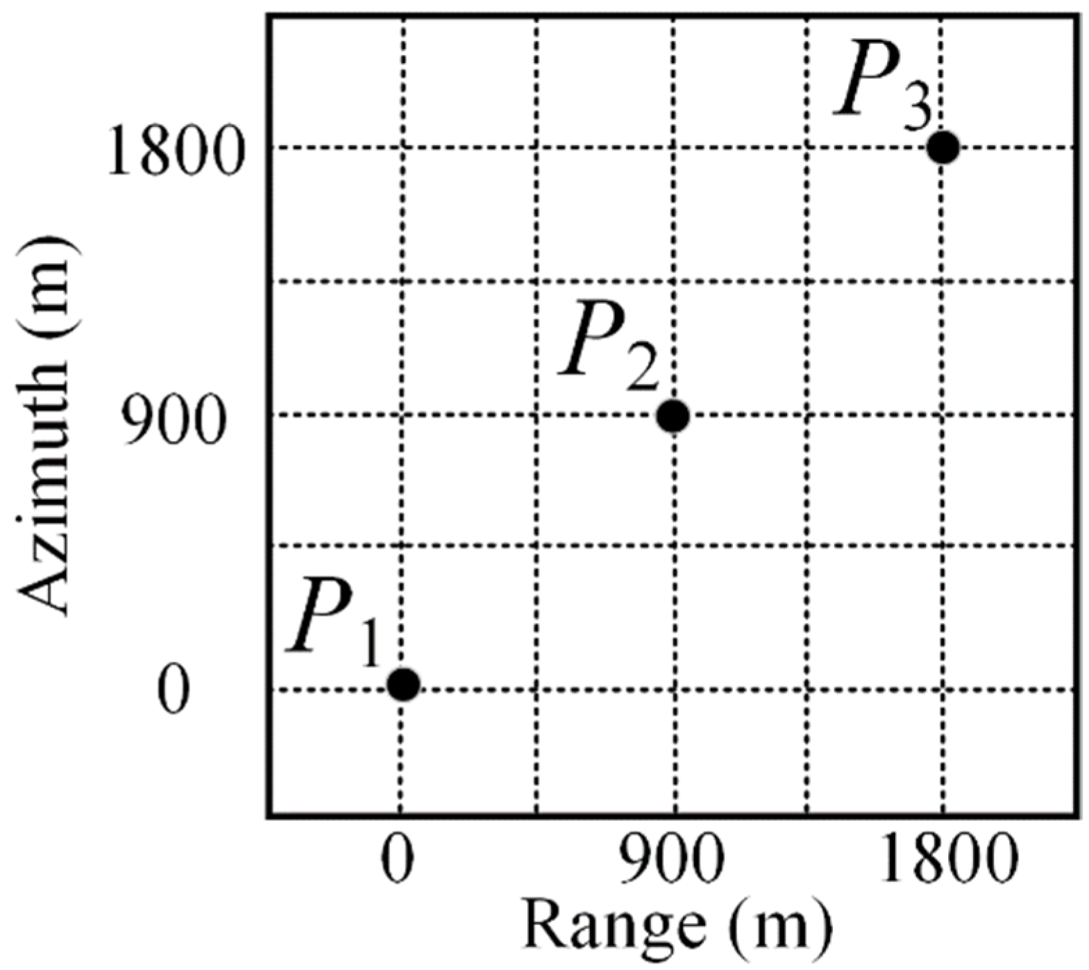
4.1. Point Target Simulation Experiment

In order to prove the effectiveness of the proposed method, three-point targets P 1 , P 2 , and P 3 are also set, as shown in Figure 6. The distance between the azimuth direction of the three-point target is 800 m and the range direction of the three-point target is 600 m. The jammer is placed at P 2 . The traditional convolution jamming method is chosen as the contrast jamming method [40].
The point target imaging result which is used as the comparison result, is shown in Figure 7a. Three points located in different positions of the scene are difficult to be jammed by a single jammer at the same time. The imaging results of traditional convolution jamming are shown in Figure 7b, and the jamming power is distributed in the whole azimuth direction. Since the different points are distributed over a wide coverage, the large jamming template is modulated to protect all the targets. Due to the sparse jamming power distribution caused by the large jamming coverage, the traditional convolution jamming method has a poor protection effect on the target in the large scene.
The imaging results of the proposed method are shown in Figure 7c. The proposed method predetermines the position of the target to be protected and generates the corresponding jammer frequency response function. The intercepted signal is modulated by the jammer frequency response function, and multiple small noise barrage blocks are generated in the SAR image. By generating multiple jamming templates to cover with multiple areas, the gain obtained by jamming is relatively high. Compared with the traditional convolution jamming method, the proposed method has better jamming effect due to better jamming gain and more concentrated jamming power.
As shown in Figure 7c–f of the 3D imaging results, the better power concentration effect of the proposed method is proved, and multiple point targets are better protected.

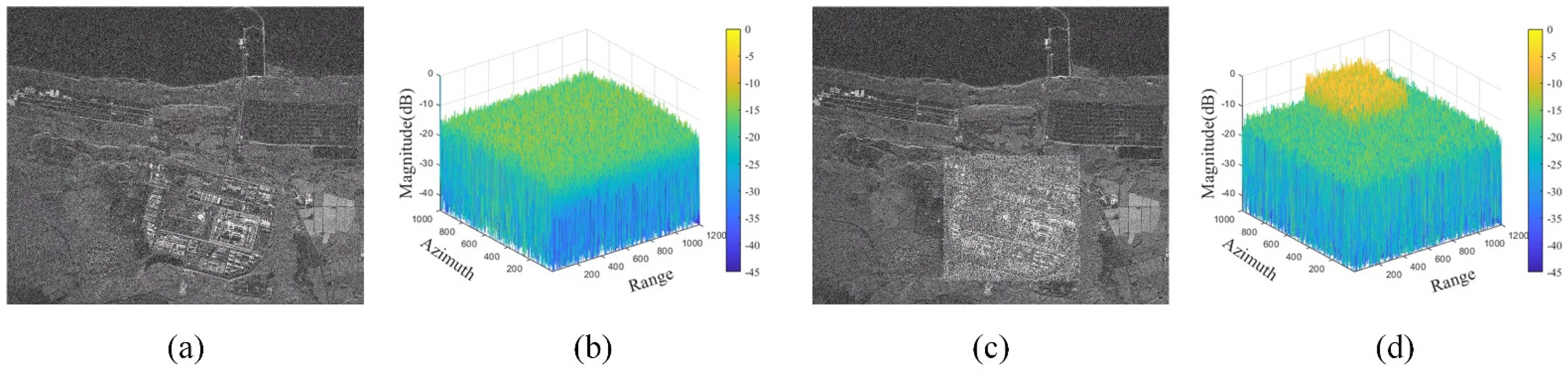
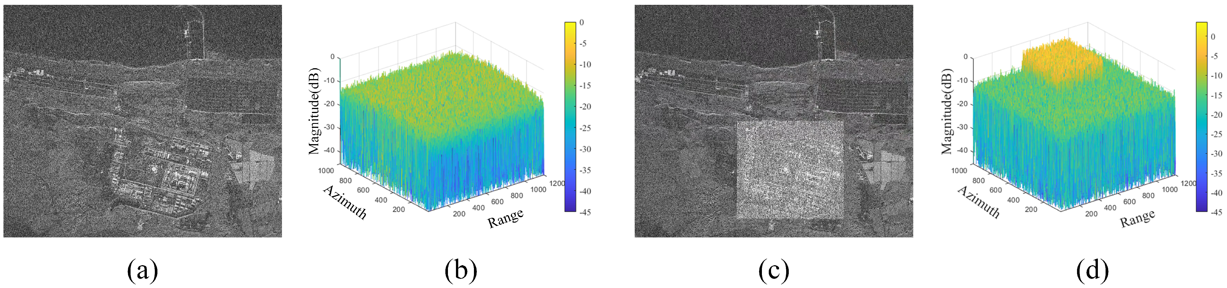
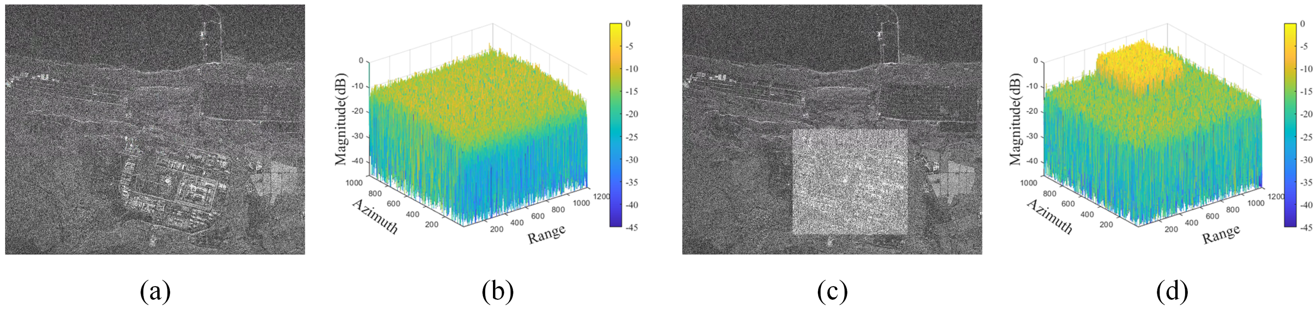
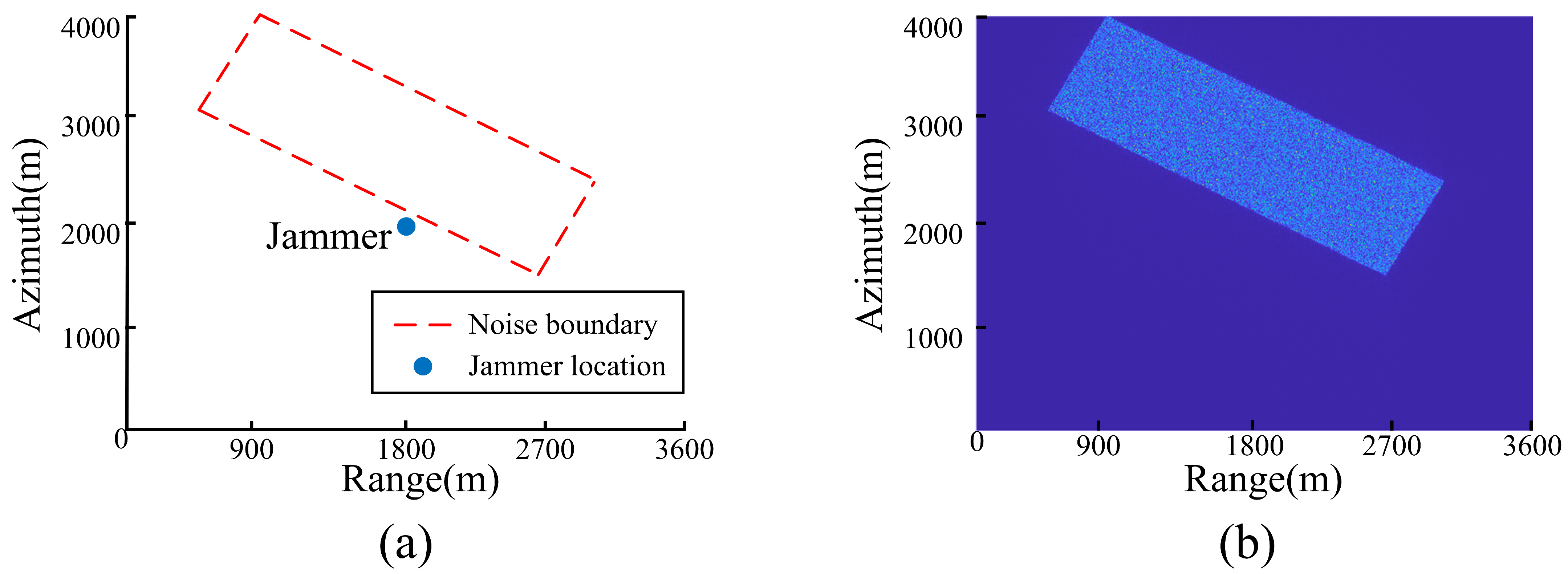
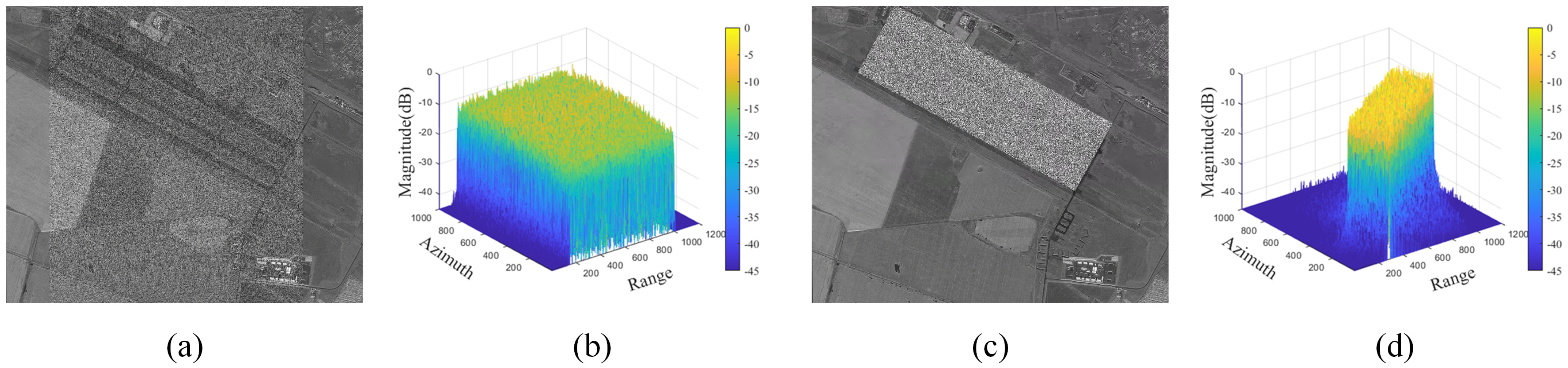
4.2. Area Target Simulation Experiment

To verify the jamming method proposed in this paper, two different real scenes without jamming are selected for simulation experiments, as shown in Figure 8 and Figure 9. The entire scene in Figure 8 is selected as the area protected for barrage, and the white box in Figure 8 is a key protected area. The white box in Figure 9 is selected as the protected for barrage. Assuming that the SAR flight trajectory is known in advance, the jammer is deployed in the center of the scene, and the working delay of the jammer is 0.
To demonstrate the effectiveness of the proposed method, structural similarity (SSIM) is introduced to quantitatively evaluate the jamming performance. Structural similarity (SSIM) is a widely used metric for quantitatively evaluating image similarity by considering three main components: luminance, contrast, and structure. The real scene and the barrage jamming scene are selected to form vectors X and Y, respectively. Then, three similarity parameters need to be defined, i.e., the luminance index L ( X , Y ) , the contrast index C ( X , Y ) , and the structure index S ( X , Y ) . Here, L ( X , Y ) reflects the similarity in average luminance between X and Y , capturing the consistency of intensity values. C ( X , Y ) measures the similarity in intensity variance, providing insight into the contrast levels of X and Y . S ( X , Y ) evaluates the correlation of local structures, emphasizing features such as edges and spatial patterns. Three similarity parameters constitute the SSIM function, which is expressed as
S S I M = L X , Y α C X , Y β S X , Y γ ,
where α , β , and γ are the weighting coefficients, and α > 0 , β > 0 , γ > 0 . We usually set to α = β = γ = 1 .
The result of jamming for the entire scene 1 is shown in Figure 10, and the jamming-to-signal ratio (JSR) at the receiving end of the radar is set to 2   d B .
The jamming of the whole scene generated by the traditional convolution method is shown in Figure 10a. The traditional convolutional method modulates a large jamming template with sparse jamming power distribution to protect the entire ROI, and the jamming gain decreases with the increase of the jamming template. The power distribution of jamming generated by traditional convolution is shown in Figure 10b. Combined with Figure 10a,b, when J S R = 2   d B , the traditional convolution jamming effect is poor, and the ROI is difficult to be well protected.
The proposed method has higher jamming power utilization efficiency by segmenting ROIs and controlling the jammer frequency response function. The jamming results of the proposed method are shown in Figure 10c, where the sub-scene size is set to 100   m × 100   m . The jamming power distribution generated by the proposed method is shown in Figure 10d. Compared with traditional jamming, more jamming power is allocated to the important target area in the ROI, the jamming power utilization efficiency is higher, and the important target area is better protected. In addition, with the segmentation of sub-scenes, the jamming of the key protection area is more accurate, and the jamming has a higher gain.
To comprehensively verify the effectiveness of the proposed method in different environments, additional simulation experiments were conducted on scene 1, with J S R = 0   d B and J S R = 2   d B , respectively. The results are shown in Figure 11 and Figure 12. It can be observed that, compared to traditional convolution jamming, the proposed method demonstrates higher power utilization efficiency and superior jamming performance under different J S R conditions, fully validating its effectiveness.
In order to quantitatively evaluate the jamming performance of different jamming methods, the metric SSIM for the jamming scenes shown in Figure 10, Figure 11 and Figure 12 was calculated and listed in Table 2. Compared with the traditional convolution method, the proposed method has a smaller SSIM under the same JSR, and the proposed method has a better jamming effect.
Table 2. Comparison different jamming using SSIM.
Methods J S R = 2   d B J S R = 0   d B J S R = 2   d B
Convolution jamming0.23770.18450.1396
Propose method0.22060.16770.1271
As shown in Figure 9, only the local scene in the ROI needs to be jammed, so the more accurate the jamming coverage, the higher the jamming power utilization. The proposed method achieves a precise and controllable jamming effect by pre-determining the position of jamming coverage and modulating the corresponding jammer frequency response function. Figure 13a illustrates the boundary coordinates of the key target in the whole scene obtained in advance, and the jammer is in the center of the scene. The frequency response function of the corresponding jammer modulated is obtained based on the acquired boundary coordinates, and the predetermined jamming power distribution is shown in Figure 13b.
The result of jamming for Figure 9 is shown in Figure 14, and the JSR at the receiving end of the radar is set to 2   d B . The results of the traditional convolution jamming targeting the local scene are shown in Figure 14a. The power distribution of jamming generated by traditional convolution is shown in Figure 14b, and the jamming power of traditional convolution jamming is scattered in the whole azimuth direction. The jamming coverage generated by traditional convolution jamming far exceeds the actual needs of the protected area. This leads to serious waste of jamming power and poor protection of key regions.
The jamming effect generated by the proposed method for the key scene is shown in Figure 14c. It can be seen that a precisely controllable jamming effect is generated by predetermining the position of jamming coverage. The jamming power distribution generated by the proposed method is shown in Figure 14d, and the jamming coverage generated by the proposed method can accurately meet the needs of real scenes. Compared with the traditional convolution jamming, the proposed method has higher jamming power utilization and jamming gain.
Through the comparison of the above experimental results, the jamming proposed in this paper can realize the flexible control of the position and coverage of the jamming under the fixed jammer, and the defects of the uncontrollable position and coverage of the traditional barrage jamming are effectively compensated. The method proposed realizes the adaptation of jamming power and scene target through the superposition of small noise templates, and the utilization efficiency of jamming power is improved. In the case of entire scene jamming and key targets jamming, the proposed method has a good jamming effect, which is consistent with the theoretical analysis.

5. Discussion

Compared with existing methods, the proposed method provides jamming effects with flexible and controllable positions and coverage, significantly improving the utilization of jamming energy. However, the proposed method still has some limitations. For instance, in barrage jamming against fine targets, there remains a certain degree of jamming energy waste. Therefore, proposing a jamming power allocation and selection strategy to achieve precise power coverage of jamming energy is undoubtedly an important research topic.

6. Conclusions

In this paper, a new barrage jamming method is proposed to solve the problem of uncontrollable jamming coverage and jamming waste. Based on the imaging properties of the LFM case and the reasonable approximation of the slant distance from the SAR to the target point, the frequency response function of the jammer is designed, which is composed of the position modulation function and the jamming coverage function. By modulating the frequency response function of the jammer, flexible and controllable jamming coverage effects can be generated. Additionally, the frequency response function of the jammer can be decomposed into slow-time-dependent parts and slow-time-independent parts, and the real-time performance of the proposed method is guaranteed by generating slow-time-independent parts offline in advance.
Compared to the current jamming methods, the position and coverage of the jamming effect generated by the proposed method are controllable, and the utilization efficiency of jamming power can be significantly improved. Moreover, the reconnaissance parameter error has little impact on the proposed method, and the protection of the scene can still be completed in the presence of errors. Finally, extensive simulation experiments demonstrate the superior performance of the proposed method. The proposed method might have a certain reference value for practical engineering applications. However, the proposed method also has certain limitations. For instance, energy waste may occur during fine-target jamming, the method relies heavily on prior information, and its ability to update prior information in dynamic scenarios is limited. These factors could impact the flexibility and robustness of the jamming. In the future, we aim to further optimize the jamming power allocation and selection strategies by integrating real-time battlefield dynamics into prior information. This will enable adaptive power allocation among sub-scenes to better accommodate more complex battlefield environments and enhance the method’s adaptability in highly dynamic scenarios. Additionally, we will explore the application of this method in multi-platform collaborative jamming to achieve more efficient electromagnetic countermeasures.

Author Contributions

Conceptualization, Z.G. and L.W.; Data curation, Z.G.; Formal analysis, Z.G. and N.L.; Funding acquisition, Z.L. and N.L.; Investigation, L.W. and Z.F.; Methodology, Z.G. and Z.F.; Project administration, X.Z., Z.L. and N.L.; Resources, N.L.; Software, X.Z., L.W., Z.G. and Z.F.; Supervision, Z.F. and N.L.; Validation, Z.G., L.W. and Z.L.; Visualization, Z.G.; Writing—original draft, Z.G. and L.W. All authors have read and agreed to the published version of the manuscript.

Funding

This research was funded by the Natural Science Foundation of Henan (242300421170) and the Graduate Education Innovation and Quality Improvement Program of Henan University (SYLYC2023075).

Data Availability Statement

The original contributions presented in the study are included in the article, further inquiries can be directed to the corresponding author.

Acknowledgments

The authors would like to thank the anonymous reviewers for their valuable and detailed comments that are crucial in improving the quality of this paper.

Conflicts of Interest

The authors declare no conflicts of interest.

References

  1. Reigber, A.; Scheiber, R.; Jager, M.; Prats-Iraola, P.; Hajnsek, I.; Jagdhuber, T.; Papathanassiou, K.P.; Nannini, M.; Aguilera, E.; Baumgartner, S.; et al. Very-high-resolution airborne synthetic aperture radar imaging: Signal processing and applications. Proc. IEEE 2013, 101, 759–783. [Google Scholar]
  2. Moreira, A.; Prats-Iraola, P.; Younis, M.; Krieger, G.; Hajnsek, I.; Papathanassiou, K.P. A tutorial on synthetic aperture radar. IEEE Geosci. Remote Sens. Mag. 2013, 1, 6–43. [Google Scholar]
  3. Li, N.; Lv, Z.; Guo, Z. Pulse RFI mitigation in synthetic aperture radar data via a three-step approach: Location, notch, and recovery. IEEE Trans. Geosci. Remote Sens. 2022, 60, 1–17. [Google Scholar]
  4. Cai, Y.; Li, J.; Yang, Q.; Liang, D.; Liu, K.; Zhang, H.; Lu, P.; Wang, R. First demonstration of RFI mitigation in the phase synchronization of LT-1 bistatic SAR. IEEE Trans. Geosci. Remote Sens. 2023, 61, 1–19. [Google Scholar] [CrossRef]
  5. Fu, Z.; Zhang, H.; Zhao, J.; Li, N.; Zheng, F. A modified 2-D notch filter based on image segmentation for RFI mitigation in synthetic aperture radar. Remote Sens. 2023, 15, 846. [Google Scholar] [CrossRef]
  6. Li, N.; Zhang, H.; Lv, Z.; Min, L.; Guo, Z. Simultaneous screening and detection of RFI from massive SAR images: A case study on European Sentinel-1. IEEE Trans. Geosci. Remote Sens. 2022, 60, 1–17. [Google Scholar]
  7. Sun, H.; Shimada, M.; Xu, F. Recent advances in synthetic aperture radar remote sensing—Systems, data processing, and applications. IEEE Geosci. Remote Sens. Lett. 2017, 14, 2013–2016. [Google Scholar]
  8. Zhou, F.; Sun, G.; Bai, X.; Bao, Z. A novel method for adaptive SAR barrage jamming suppression. IEEE Geosci. Remote Sens. Lett. 2012, 9, 292–296. [Google Scholar] [CrossRef]
  9. Cheng, Y.; Zhu, D.; Jin, G.; Zhang, J.; Niu, S.; Wang, Y. A novel intrapulse repeater mainlobe-jamming suppression method with MIMO-SAR. IEEE Geosci. Remote Sens. Lett. 2022, 19, 1–5. [Google Scholar]
  10. Bang, H.; Wang, W.-Q.; Zhang, S.; Liao, Y. FDA-based space–time–frequency deceptive jamming against SAR imaging. IEEE Trans. Aerosp. Electron. Syst. 2022, 58, 2127–2140. [Google Scholar] [CrossRef]
  11. Bai, B.; Liu, Y.; Song, L.; Li, X.; Ding, Y.; Zhang, X. Passive radar jamming: A novel method using time-varying plasma. IEEE Access 2019, 7, 120082–120088. [Google Scholar]
  12. Li, Y.; Huang, D.; Xing, S.; Wang, X. A review of synthetic aperture radar jamming technique. J. Radars 2020, 9, 753–764. [Google Scholar]
  13. Huang, Y.; Zhao, B.; Tao, L.; Chen, Y.; Hong, W. Review of synthetic aperture radar interference suppression. J. Radars 2020, 9, 86–106. [Google Scholar]
  14. Sun, Q.; Shu, T.; Tang, M.; Yu, K.-B.; Yu, W. Effective moving target deceptive jamming against multichannel SAR-GMTI based on multiple jammers. IEEE Geosci. Remote Sens. Lett. 2020, 17, 441–445. [Google Scholar]
  15. Chang, X.; Li, Y.; Zhao, Y. An improved scattered wave deceptive jamming method based on a moving jammer beam footprint against a three-channel short-time SAR GMTI. IEEE Sens. J. 2021, 21, 4488–4499. [Google Scholar]
  16. Cheng, D.; Liu, Z.; Guo, W.; Gao, S.; Li, N. A repeater-type SAR deceptive jamming method based on joint encoding of amplitude and phase in the intra-pulse and inter-pulse. Remote Sens. 2022, 14, 4597. [Google Scholar] [CrossRef]
  17. Dong, C.; Chang, X. A novel scattered wave deceptive jamming against three channel SAR GMTI. IEEE Access 2018, 6, 53882–53889. [Google Scholar]
  18. Huang, B.; Wang, W.-Q.; Zhang, S.; Wang, H.; Gui, R.; Lu, Z. A novel approach for spaceborne SAR scattered-wave deceptive jamming using frequency diverse array. IEEE Geosci. Remote Sens. Lett. 2020, 17, 1568–1572. [Google Scholar]
  19. Zhang, J.; Dai, D.; Xing, S.; Xiao, S.; Pang, B. A Novel Barrage Repeater Jamming against SAR-GMTI. In Proceedings of the 10th European Conference on Antennas and Propagation, Davos, Switzerland, 10–15 April 2016; pp. 1–5. [Google Scholar]
  20. Cheng, D.; Li, N.; Shu, G.; Guo, Z. Multiple-Phases-Sectionalized-Modulation SAR Barrage Jamming Method Based on NLFM Signal. In Proceedings of the 2022 IEEE International Conference on Image Processing, Bordeaux, France, 16–19 October 2022; pp. 3046–3050. [Google Scholar]
  21. Garmatyuk, D.S.; Narayanan, R.M. ECCM capabilities of an ultrawideband bandlimited random noise imaging radar. IEEE Trans. Aerosp. Electron. Syst. 2002, 38, 1243–1255. [Google Scholar] [CrossRef]
  22. Liu, Q.; Xing, S.; Wang, X.; Dong, J.; Dai, D. A strip-map SAR coherent jammer structure utilizing periodic modulation technology. Prog. Electromagn. Res. B 2011, 28, 111–128. [Google Scholar] [CrossRef]
  23. Wang, W.; Cai, J. A technique for jamming bi- and multistatic SAR systems. IEEE Geosci. Remote Sens. Lett. 2007, 4, 80–82. [Google Scholar] [CrossRef]
  24. Wang, S.; Yu, L.; Ni, J.; Zhang, G. A study on the active deceptive jamming to the SAR. Acta Electron. Sin. 2003, 31, 1900. [Google Scholar]
  25. Liu, Y.-X.; Zhang, Q.; Xiong, S.-C.; Wang, H.-B.; Yuan, H.; Luo, Y. A Multiple-False-Target ISAR Shape Deception Jamming Method Based on Improved Template Multiplication Modulated Time-Delay Algorithm and Sub-Nyquist Sampling. Remote Sens 2023, 15, 5015. [Google Scholar]
  26. Sun, G.; Zhou, F.; Xing, M.; Bao, Z. Deceptive-jamming technology against the SAR based on the deceptive scene and real-time analyses. J. Xidian Univ. 2009, 36, 813–818. [Google Scholar]
  27. Zhou, F.; Zhao, B.; Tao, M.; Bai, X.; Chen, B.; Sun, G. A large scene deceptive jamming method for space-borne SAR. IEEE Trans. Geosci. Remote Sens. 2013, 51, 4486–4495. [Google Scholar]
  28. Yang, K.; Ye, W.; Ma, F.; Li, G.; Tong, Q. A large-scene deceptive jamming method for space-borne SAR based on time-delay and frequency-shift with template segmentation. Remote Sens. 2019, 12, 53. [Google Scholar] [CrossRef]
  29. Yang, K.; Ye, W.; Wu, X.; Ma, F.; Li, G. Fast generation of deceptive jamming signal against space-borne SAR. IEEE J. Sel. Top. Appl. Earth Obs. Remote Sens. 2020, 13, 5580–5596. [Google Scholar]
  30. Chang, X.; Dong, C. A barrage noise jamming method based on double jammers against three-channel SAR GMTI. IEEE Access 2019, 7, 18755–18763. [Google Scholar]
  31. Wang, Y.; Liu, G.; Ma, X.; Song, C.; Jin, G.; Li, L. A Convolution Modulation Jamming Method Based on the Optimal Combination of Noise Templates. IEEE Geosci. Remote Sens. Lett. 2024, 21, 1–5. [Google Scholar]
  32. Liu, Y.; Wang, W.; Dai, S.; Rao, B.; Wang, G. Transmitter Power Comparison between Incoherent Noise and Coherent Deceptive Jamming against Synthetic Aperture Radar. In Proceedings of the 2017 IEEE Microwaves, Radar and Remote Sensing Symposium, Kiev, Ukraine, 29–31 August 2017; pp. 279–284. [Google Scholar]
  33. Chen, T.; Zhe, Z. Research on Smart Noise Frequency Modulation Jamming Technology Based on Convolution Modulation. In Proceedings of the 2024 9th International Conference on Electronic Technology and Information Science (ICETIS), Hangzhou, China, 17–19 May 2024; pp. 195–199. [Google Scholar]
  34. Abouelfadl, A.; Samir, A.M.; Ahmed, F.M.; Asseesy, A.H. Performance Analysis of LFM Pulse Compression Radar under Effect of Convolution Noise Jamming. In Proceedings of the 2016 33rd National Radio Science Conference, Aswan, Egypt, 22–25 February 2016; pp. 282–289. [Google Scholar]
  35. Gong, S.; Wei, X.; Li, X.; Ling, Y. Mathematic principle of active jamming against wideband LFM radar. J. Syst. Eng. Electron. 2015, 26, 50–60. [Google Scholar]
  36. Hao, H.; Zeng, D.; Ge, P. Research on the Method of Smart Noise Jamming on Pulse Radar. In Proceedings of the 2015 Fifth International Conference on Instrumentation and Measurement, Computer, Communication and Control, Qinhuangdao, China, 18–20 September 2015; pp. 1339–1342. [Google Scholar]
  37. Gong, S.; Wei, X.; Li, X.; Ling, Y. Two-dimensional discretized coherent noise jamming method to wideband LFM radar. Prog. Electromagn. Res. Lett. 2014, 49, 15–22. [Google Scholar] [CrossRef]
  38. Ammar, M.A.; Hassan, H.A.; Abdel-Latif, M.S.; Elgamel, S.A. Performance evaluation of SAR in presence of multiplicative noise jamming. In Proceedings of the 2017 34th National Radio Science Conference (NRSC), Alexandria, Egypt, 13–16 March 2017; pp. 213–220. [Google Scholar]
  39. Zhang, Y. Technology of Smart Noise Jamming Based on Multiplication Modulation. In Proceedings of the 2011 International Conference on Electric Information and Control Engineering, Wuhan, China, 15–17 April 2011; pp. 4557–4559. [Google Scholar]
  40. Ye, W.; Ruan, H.; Zhang, S.; Yan, L. Study of Noise Jamming Based on Convolution Modulation to SAR. In Proceedings of the 2010 International Conference on Computer, Mechatronics, Control and Electronic Engineering, Changchun, China, 24–26 August 2010; pp. 169–172. [Google Scholar]
  41. Zhou, C. Study of convolution jamming technology of synthetic aperture radar. Shipboard Electron. Countermeas. 2013, 35, 6–10. [Google Scholar]
  42. Fang, M.; Wang, G.; Lei, L. Study on 2D Noise Convolution Modulation Jamming to SAR. Mod. Def. Technol. 2014, 42, 139–144+160. [Google Scholar]
  43. Jiang, J.; Wu, Y.; Wang, H.; Chen, J. A dense false target jamming technique against SAR-GMTI. Shipboard Electron. Countermeas. 2016, 39, 9–14. [Google Scholar]
  44. Huang, D.; Xing, Q.; Li, Y.; Liu, Y.; Xiao, S. Smart jamming method against SAR based on multiplication modulation. Syst. Eng. Electron. 2020, 43, 3160–3168. [Google Scholar]
  45. Huang, D.; Xing, S.; Liu, Y.; Li, Y.; Xiao, S. Fake SAR signal generation method based on noise convolution modulation. J. Radars 2020, 9, 898–907. [Google Scholar]
  46. Wang, Y.; Liu, Z.; Huang, Y.; Li, N. Multitarget Barrage Jamming Against Azimuth Multichannel HRWS SAR via Phase Errors Modulation of Transmitted Signal. IEEE Geosci. Remote Sens. Lett. 2024, 21, 1–5. [Google Scholar] [CrossRef]
Figure 1. Geometric model for space-borne SAR jamming.
Remotesensing 17 01303 g001
Figure 2. Working flowchart of the jammer.
Remotesensing 17 01303 g002
Figure 3. Flowchart of the proposed method.
Remotesensing 17 01303 g003
Figure 4. Jamming scene template segmentation diagram.
Remotesensing 17 01303 g004
Figure 5. Effects of SAR platform velocity error, shortest slant distance error, and carrier frequency error. (a) SAR platform velocity error against x ; (b) SAR shortest slant distance error against x ; (c) SAR carrier frequency error against x ; (d) SAR platform velocity error against p a ; (e) SAR shortest slant distance error against p a ; (f) SAR carrier frequency error against p a .
Remotesensing 17 01303 g005
Figure 6. The scatterers array of three points.
Remotesensing 17 01303 g006
Figure 7. SAR image results with different jamming methods. (a) Without jamming. (b) Traditional convolution jamming. (c) Proposed jamming. (df) The 3D imaging results of (a), (b), and (c), respectively.
Remotesensing 17 01303 g007
Figure 8. Real scene 1.
Remotesensing 17 01303 g008
Figure 9. Real scene 2.
Remotesensing 17 01303 g009
Figure 10. Barrage jamming for the entire scene with J S R = 2   d B . (a) Traditional convolution jamming; (b) 3D presentation of the jamming power distribution of traditional convolutional jamming; (c) Proposed jamming; (d) 3D presentation of the jamming power distribution of proposed jamming.
Remotesensing 17 01303 g010
Figure 11. Barrage jamming for the entire scene with J S R = 0   d B . (a) Traditional convolution jamming; (b) 3D presentation of the jamming power distribution of traditional convolutional jamming; (c) Proposed jamming; (d) 3D presentation of the jamming power distribution of proposed jamming.
Remotesensing 17 01303 g011
Figure 12. Barrage jamming for the entire scene with J S R = 2   d B . (a) Traditional convolution jamming; (b) 3D presentation of the jamming power distribution of traditional convolutional jamming; (c) Proposed jamming; (d) 3D presentation of the jamming power distribution of proposed jamming.
Remotesensing 17 01303 g012
Figure 13. Jamming template generation. (a) Coordinates of the protected target in the scene; (b) Generate noise templates based on coordinates.
Remotesensing 17 01303 g013
Figure 14. Barrage jamming for the part scene. (a) Traditional convolution jamming; (b) 3D presentation of the jamming power distribution of traditional convolutional jamming; (c) Proposed jamming; (d) 3D presentation of the jamming power distribution of proposed jamming.
Remotesensing 17 01303 g014
Table 1. Main system parameters of simulation.
ParametersValues
Carrier frequency5.4 GHz
Platform velocity6637 m/s
Pulse width51 μs
Band width42 MHz
Pulse repetition frequency1663 Hz
Closest slant range800 km
Antenna length12.3 m
Disclaimer/Publisher’s Note: The statements, opinions and data contained in all publications are solely those of the individual author(s) and contributor(s) and not of MDPI and/or the editor(s). MDPI and/or the editor(s) disclaim responsibility for any injury to people or property resulting from any ideas, methods, instructions or products referred to in the content.

