Technical Note

An Enhanced Phase Gradient Autofocus Algorithm for SAR: A Fractional Fourier Transform Approach

1
School of Electronic Engineering, Soongsil University, Seoul 06978, Republic of Korea
2
Department of Intellignet Semiconductors, Soongsil University, Seoul 06978, Republic of Korea
*
Author to whom correspondence should be addressed.
Remote Sens. 2025, 17(7), 1216; https://doi.org/10.3390/rs17071216
Submission received: 31 January 2025 / Revised: 7 March 2025 / Accepted: 26 March 2025 / Published: 29 March 2025

Abstract

:
Synthetic aperture radar (SAR) technology is one of the imaging radar technologies receiving the most attention worldwide. The main purpose is to detect targets in the area of interest in different settings, such as day/night, various weather conditions, etc. Phase gradient autofocusing (PGA) algorithms have been widely used for autofocus in SAR imaging. Conventional PGA methods in stripmap SAR apply dechirping to switch the range-compressed phase history-domain signal to a form equivalent to that in spotlight mode. However, this switching method has inherent limitations in phase error estimation, leading to degraded autofocusing performance. To address this issue, we introduce an FrFT-based switching method that provides more precise and fast autofocus. Additionally, this method enables effective detection and extraction of moving targets in the environment where moving targets are present. Moving targets introduce additional phase errors that hinder accurate autofocus, making it essential to isolate and process them separately. We carried out practical experiments with an X-band chirp pulse SAR system to verify the proposed method and mount the system on an automobile.

1. Introduction

Synthetic aperture radar (SAR) has been studied as one of the imaging radars, which is substituted for various optical sensors [1]. The reason is that SAR can monitor the area of interest, generating a real image such as a camera. SAR can also generate images not only day or night but also in all weather conditions [2]. Recent SAR studies include many applications according to different purposes of interest, such as polarimetry-SAR, interferometry SAR, video SAR, etc. [3]. Therefore, beyond conventional radars, SAR will become an important technology in the future mobility society as the key sensor in a variety of applications. Conventionally, SAR technology can be divided into radar hardware systems and signal processing algorithms. The difference from regular radar is the special signal processing algorithm. In SAR signal processing, the matched filtering (or convolution) is performed in the range direction (fast time) and the azimuth direction (slow time or Doppler direction) using the synthetic aperture of an antenna on the moving measurement platform. The matched filtering in both directions focuses the received signals as each point target, and it leads to improving the resolution of the target with low noise levels and generating high-quality images. Therefore, in order to be used in various applications, SAR signal processing requires matched filtering technology that can accurately focus the target in the range and azimuth directions. For example, due to unexpected errors in the measurement environment, it is hard to estimate accurate parameters (Doppler center frequency, Doppler rate, etc.) [4,5]. The above errors hinder accurate matched filtering, and thus the expected impulse response function (IRF) cannot be generated for each target. In other words, the resolution of the target decreases, unwanted ghost signals occur, and the side-lobe level increases. In conclusion, the extraction of clear and high-resolution SAR images becomes difficult. One of the methods to solve these problems is the phase gradient autofocusing (PGA) algorithm. The purpose of the PGA algorithm in SAR processing is to strongly compensate for the phase error of defocused complex single-look images. The remaining high-order phase error terms, which are unmatched in the final compressed signal, are extracted in the PGA process. These terms can be used as a matched filter to turn the defocused image into a high-resolution SAR image [6]. It is the widely used autofocusing method in the SAR community and has the advantage of being simple and low in complexity of signal processing. However, when the remaining phase error terms cannot be extracted and not estimated accurately, the computational burden can be increased and autofocusing performance cannot be properly performed [7]. As a lot of researchers have tried to find the reasons and proposed various solutions, nowadays, several estimation theories or autofocusing methods for PGA are devised to overcome these problems [8,9,10].
In this work, we propose an improved autofocusing algorithm that is designed on the PGA technique and the fractional Fourier transform (FrFT) [11]. FrFT offers advantages in signal representation and transformation, making it widely used in various signal-processing applications [12]. It is particularly effective in maximizing the utilization of signal characteristics [13] and is applied to identify and separate desired signals from complex environments [14,15]. Conventional PGA algorithms in stripmap SAR apply dechirping (deramping), which is essential for switching the range-compressed phase history-domain signal from a stripmap mode to the spotlight mode [8,10,16,17]. However, the conventional dechirping process has inherent limitations in the quality of the equivalent image-domain signal, where phase error estimation is applied. To overcome these limitations, we introduce an enhanced switching method using FrFT. By leveraging FrFT, we improve the quality of the equivalent image-domain signal, effectively suppressing interference from undesired signals and surrounding noise, thereby enabling more precise autofocus. Additionally, the proposed switching method facilitates the detection and extraction of moving targets. When a moving target signal is present among stationary target signals, its unique additional phase error distorts accurate phase gradient estimation. Furthermore, due to their distinct Doppler parameters, moving targets must be separated and processed independently from stationary targets [18,19]. Therefore, isolating the moving target signal before executing PGA is crucial. The proposed FrFT-based switching method not only improves the accuracy of phase error estimation but also enables the separation of moving target signals, ensuring robust performance across all scenarios.
This paper is organized as follows: Section 2 introduces the background theory of conventional PGA algorithms and FrFT, which form the foundation of the proposed autofocusing technique. Section 3 describes the proposed algorithm in detail and presents the experimental results using real SAR data collected from an automobile platform to verify its effectiveness. Finally, Section 4 summarizes the conclusions of this study.

2. Phase Gradient Autofocusing Algorithm with Fractional Fourier Transform

For the proposed autofocusing algorithm, the principles of the PGA algorithm and the FrFT method are introduced in this section. Specifically, based on a detailed description of each technique, we introduce the overall process of the proposed algorithm.

2.1. Phase Gradient Autofocusing Algorithm

The purpose of the phase gradient autofocusing algorithm (PGA) in SAR processing is to provide a robust compensation for the phase error on the defocused complex single-look image. The PGA process consists of the following steps: (1) switching from stripmap to spotlight mode using dechirping, (2) performing an azimuth Fourier transform, (3) circular shifting, (4) windowing, and (5) phase error estimation and correction (Figure 1a). First, dechirping is performed, thus generating an equivalent range-compressed phase history-domain signal. Then, an azimuth Fourier transform is performed to generate an equivalent image-domain signal. These two steps ensure that the stripmap mode signal maintains the same Fourier pair between the range-compressed domain signal and the image-domain signal as in the spotlight mode. This process leads to the generation of the equivalent range-compressed domain signal and the equivalent image-domain signal in the stripmap mode, as shown in Figure 2a. Once the equivalent image-domain signal is obtained, circular shifting, windowing, and phase error estimation and correction are iteratively performed to remove phase errors. The equivalent range-compressed domain signal with phase error is introduced as follows:
F n u = F n ( u ) e x p j [ ϕ n u + ϕ e u ]
The subscript n refers to the nth range bin, and u is the relative position along the synthetic aperture. F n ( u ) and ϕ n u are the magnitude and phase, respectively. ϕ e u is the phase error for compensation. The equivalent image-domain signal with phase error is introduced as follows:
F F n u = m h x a m , n s x x m , n ,
where h x = F exp j ϕ e u represents the Fourier transform of the phase error, a m , n   s x x m , n are the target-induced impulse response functions, * denotes convolution, and m indicates the number of targets [6]. To analyze the phase error, the circular shifting process is carried out to align the strong scatterers, followed by the windowing process, which allows us to distinguish between the signal associated with the dominant blur from that of the surrounding targets. In the windowing process, a key factor for accurate phase error estimation is the clear separation between the dominant target and the surrounding targets. After the above process, the phase error gradient of the defocused SAR data is estimated from the equation below through the phased information collected by windowing each shifted range. A linear unbiased minimum variance (LUMV) estimation of the gradient of the phase error ϕ e u is determined as follows [6]:
ϕ ˙ ^ l u m v u = n I m G n u G n u n G n u 2 = ϕ ˙ ϵ u + n G n u 2 θ ˙ n ( u ) n G n u 2 ,
where g n x denotes the shifted and windowed image-domain signal, and G n u = G n u exp ( j [ ϕ e u + θ n u ] ) is the inverse Fourier transform. Therefore, this LUMV estimation leads to the smallest error term by the gradient of the actual phase error, ϕ ˙ ϵ u , and by repeated iteration. In addition, depending on various environmental conditions, it can be replaced by other phase estimation methods. It can lead to the improvement of final SAR-focusing results. The above steps of center shifting and windowing help operate the estimation function as well as the PGA kernel. The obtained ϕ ˙ ϵ u generates the phase correction function e j ϕ ˙ ϵ u , and the phase curvature estimation (PCA) can be made by double derivative [10].
ϕ ˙ ϵ u 1 = a r g k g k , l 1 · g k , l 2 · g k , l + 1 ,
where l is the azimuth index number. Based on the above phase-estimated data, the process is operated iteratively. Through this iterative process, the SAR signals become more focused and generate clear SAR images.

2.2. Fractional Fourier Transform

In time–frequency representations (TFRs), signals are typically described within a two-dimensional plane defined by orthogonal time and frequency axes. This plane, known as the time–frequency plane, serves as the basis for understanding the fractional Fourier transform (FrFT). The FrFT transforms a signal into a fractional Fourier domain (FrFD), which is obtained by rotating the time axis by an angle α [11]. In Figure 3a, the FrFD is represented in the time–frequency plane. When the rotation angle is 0 radians, the FrFD corresponds to the time domain, whereas at π / 2 radians, it corresponds to the frequency domain. Unlike conventional Fourier transforms, the FrFT allows signals to be analyzed not only in the time and frequency domains but also at any intermediate orientation within the time–frequency plane. The power spectrum in a specific FrFD corresponds to the Wigner distribution projected onto that FrFD [20], as illustrated in Figure 3a.
Given this characteristic, the FrFT is utilized in PGA to perform the switching process from the stripmap mode to the spotlight mode. As shown in Figure 2b, this method enables the direct transformation of the range-compressed domain signal into the equivalent image-domain signal. Compared to conventional approaches, the proposed FrFT-based switching method achieves a wider fractional bandwidth, resulting in improved resolution and a lower PSLR (peak side-lobe ratio) in the equivalent image-domain signal [13]. This enhancement effectively reduces interference caused by surrounding signals during the windowing process.
Furthermore, the FrFT enables the detection and extraction of moving targets. In SAR-received signals, each range bin contains a corresponding Doppler frequency signal. The Doppler chirp rate of a stationary target follows Equation (5) [1], whereas a moving target introduces a different Doppler chirp rate, as shown in Equation (6) [21].
K a τ 2 V s 2 λ R 0 τ
K a τ 2 V s V a 2 λ R 0 τ ,
where λ is the wavelength of centroid frequency in chirp pulse signal, V s is the velocity of the radar platform, V a is the along-track velocity of the moving target, and R 0 τ is the slant range along the range sample time. When a moving target signal is present, the rotation angle with the maximum peak power differs from that of the expected stationary target case (Figure 3b). From this difference, the presence of a moving target can be identified by FrFT. Once detected, the moving target signal can be effectively extracted through filtering in the FrFD using the measured rotation angle.
In Section 3, we provide a detailed explanation of the proposed autofocusing algorithm using FrFT, which enables more precise autofocusing and enhances autofocusing performance in environments where moving targets are present by facilitating their separation.

3. Autofocusing Algorithm: FrFT-PGA

In this section, we introduce the detailed implementation of the enhanced PGA algorithm incorporating the proposed FrFT-based switching method for both scenarios: with and without a moving target. To demonstrate its effectiveness, we present the results of practical experiments conducted using SAR raw data acquired from an automobile platform with a side-looking measurement setup and an X-band radar. The system parameters used in the experiments are summarized in Table 1.

3.1. Without Moving Target Signal

When the received signal does not contain a moving target, the proposed algorithm follows the outlined method in Figure 1b. As shown in Figure 1b, the proposed method consists of five steps:
(1)
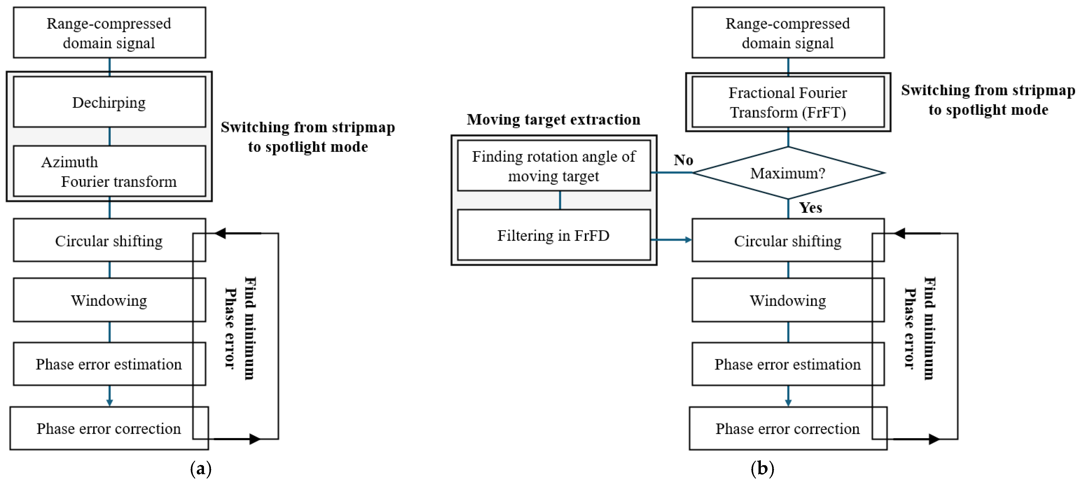
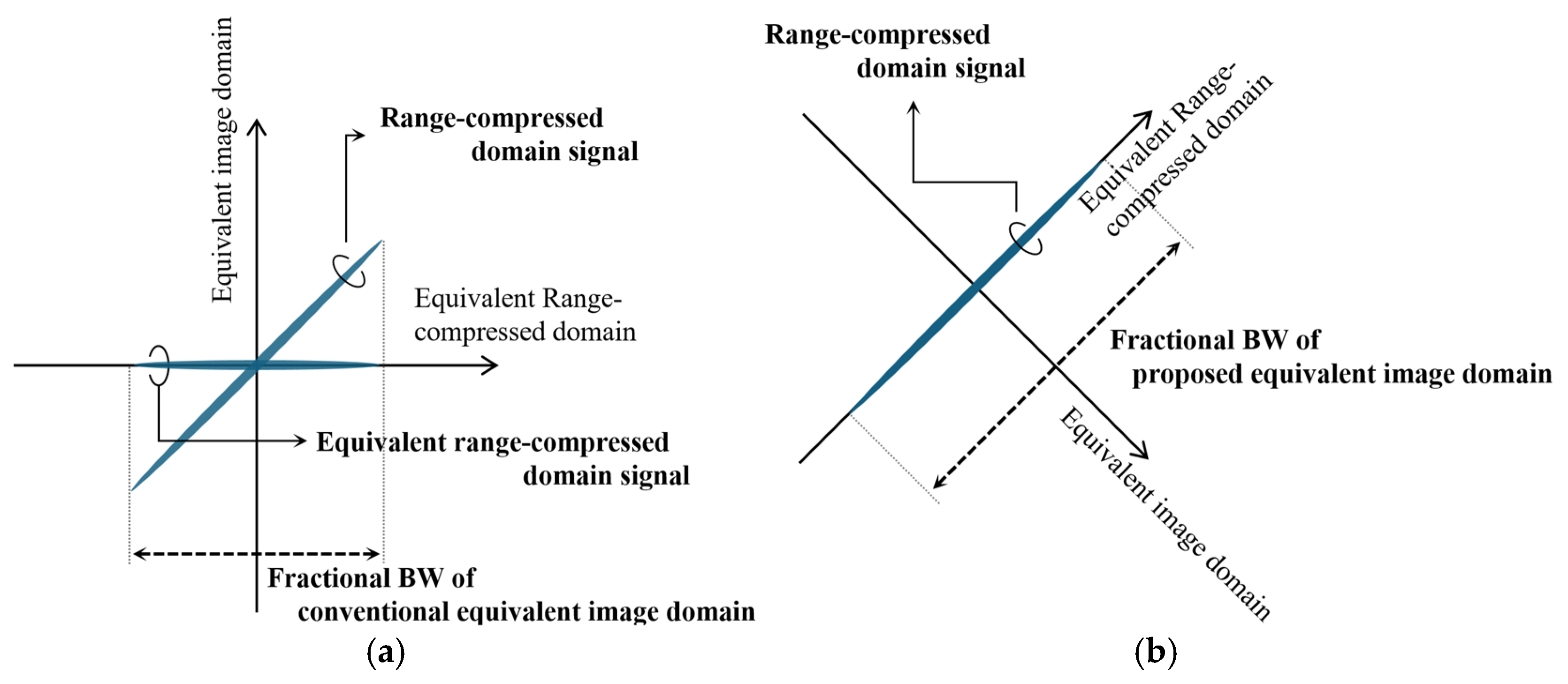
FrFT-based switching from a stripmap to the spotlight mode: as described in Section 2.2, FrFT is applied to obtain the equivalent image-domain signal with improved resolution and lower PSLR.
(2)
Circular shifting: the interested signal is arranged.
(3)
Windowing: This step blocks unwanted signals, allowing for accurate phase extraction of the desired signal. The windowed signal in the proposed algorithm exhibits less interference compared to conventional algorithms.
(4)
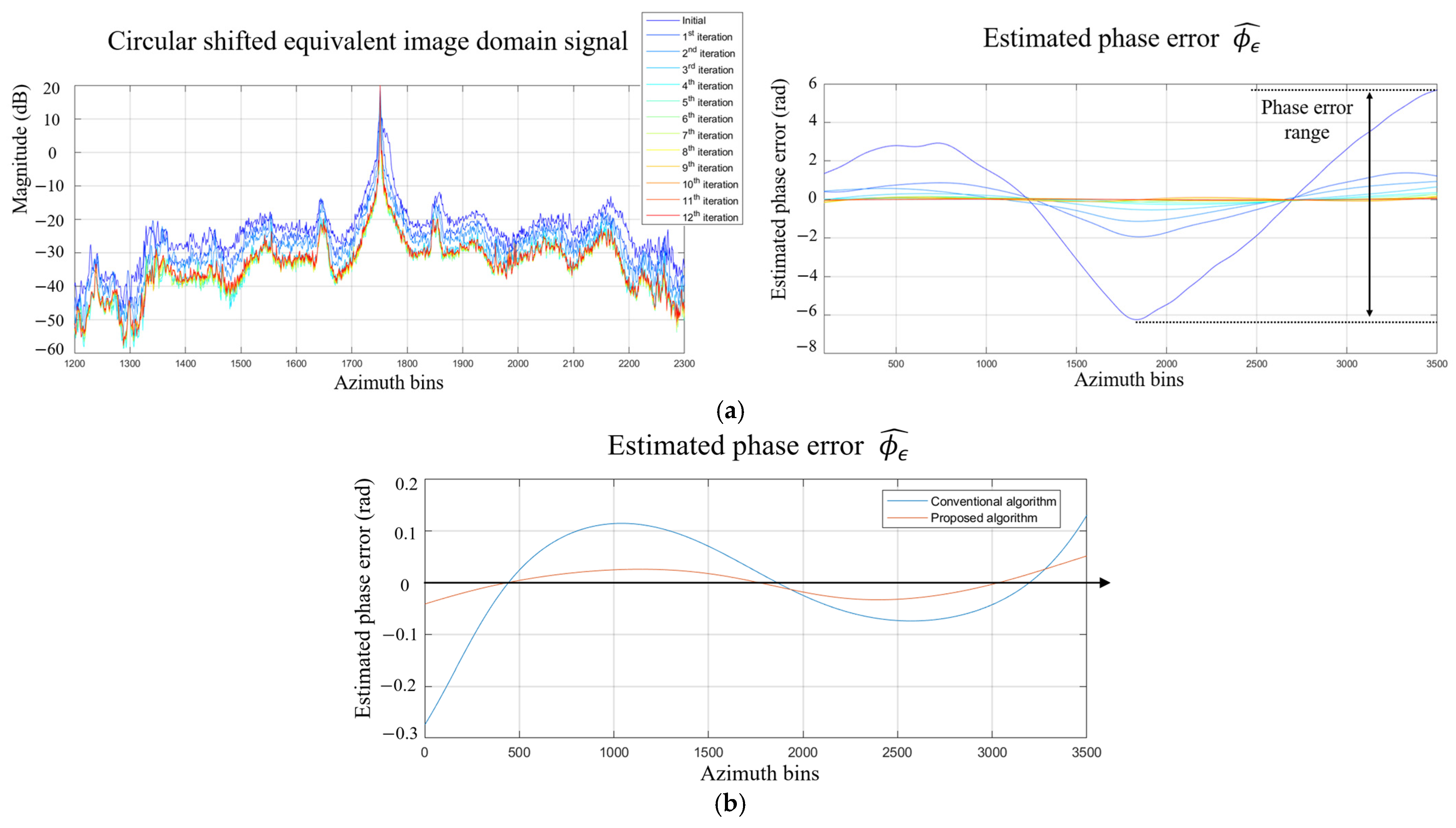
Phase error estimation and compensation: After widowing, phase error is estimated using Equation (3), and compensation is applied accordingly. Figure 4a illustrates that the proposed algorithm involves performing Steps 2, 3, and 4. By repeatedly executing these steps, the estimated phase error ( ϕ ϵ ^ ) gradually decreases. The difference between the maximum and minimum values of the estimated phase error is defined as the phase error range. Table 2 shows the variation of this range. To achieve a phase error range smaller than 0.1 rad, the proposed algorithm requires 11 iterations, whereas the conventional algorithm needs 28 iterations. Figure 4b compares the estimated phase error of the proposed and conventional algorithms at the 11th iteration.
(5)
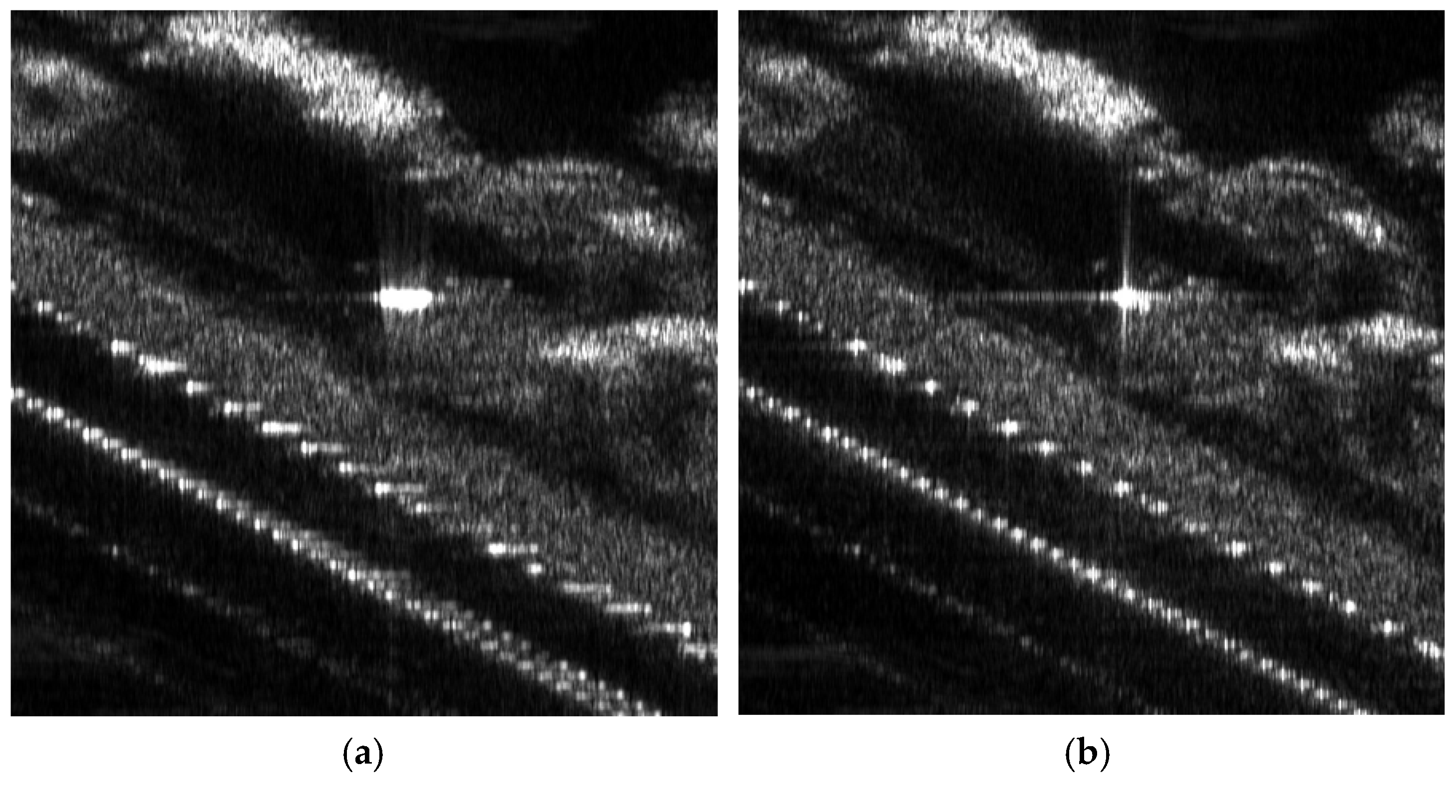
Final image: The phase error-compensated range-compressed domain signal undergoes azimuth-matched filtering to generate the final autofocused image. Figure 5 presents the final autofocused image obtained using the proposed algorithm.

3.2. With a Moving Target Signal

When moving targets are present in the received signal, the moving target detection and extraction processes are incorporated into the proposed algorithm.
(1)
FrFT-based switch from a stripmap to the spotlight mode: During the FrFT-based switching method, it is determined whether the signal exhibits maximum peak power at the expected rotation angle. This is assessed by comparing the peak power in the current rotation angle with that in adjacent angles.
(2)
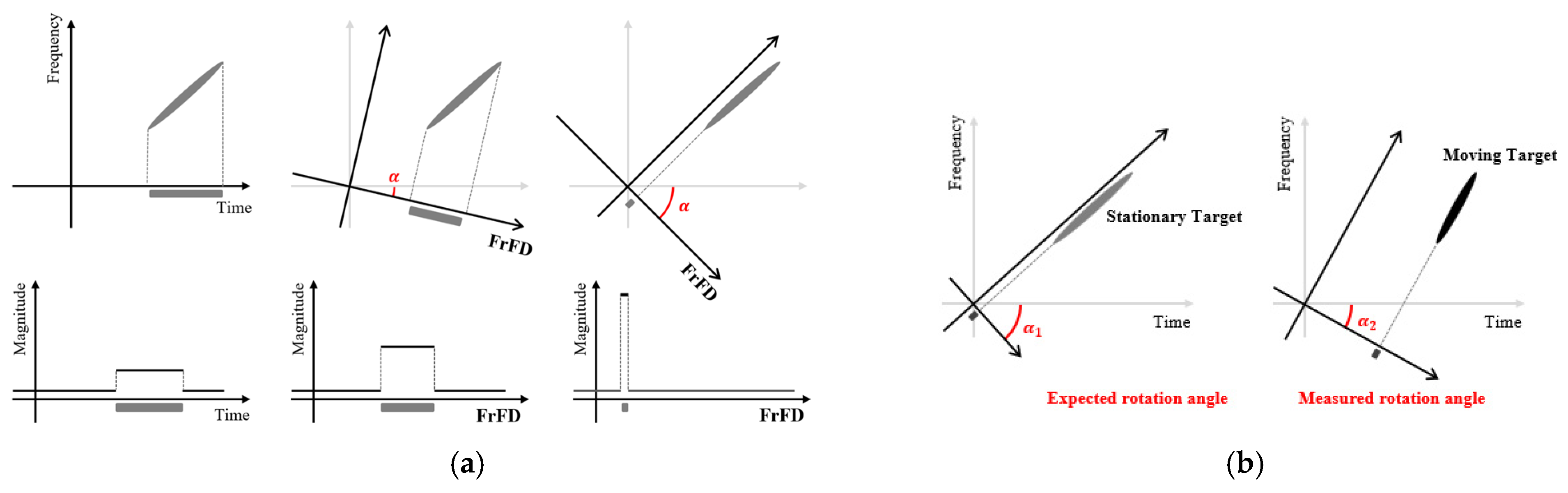
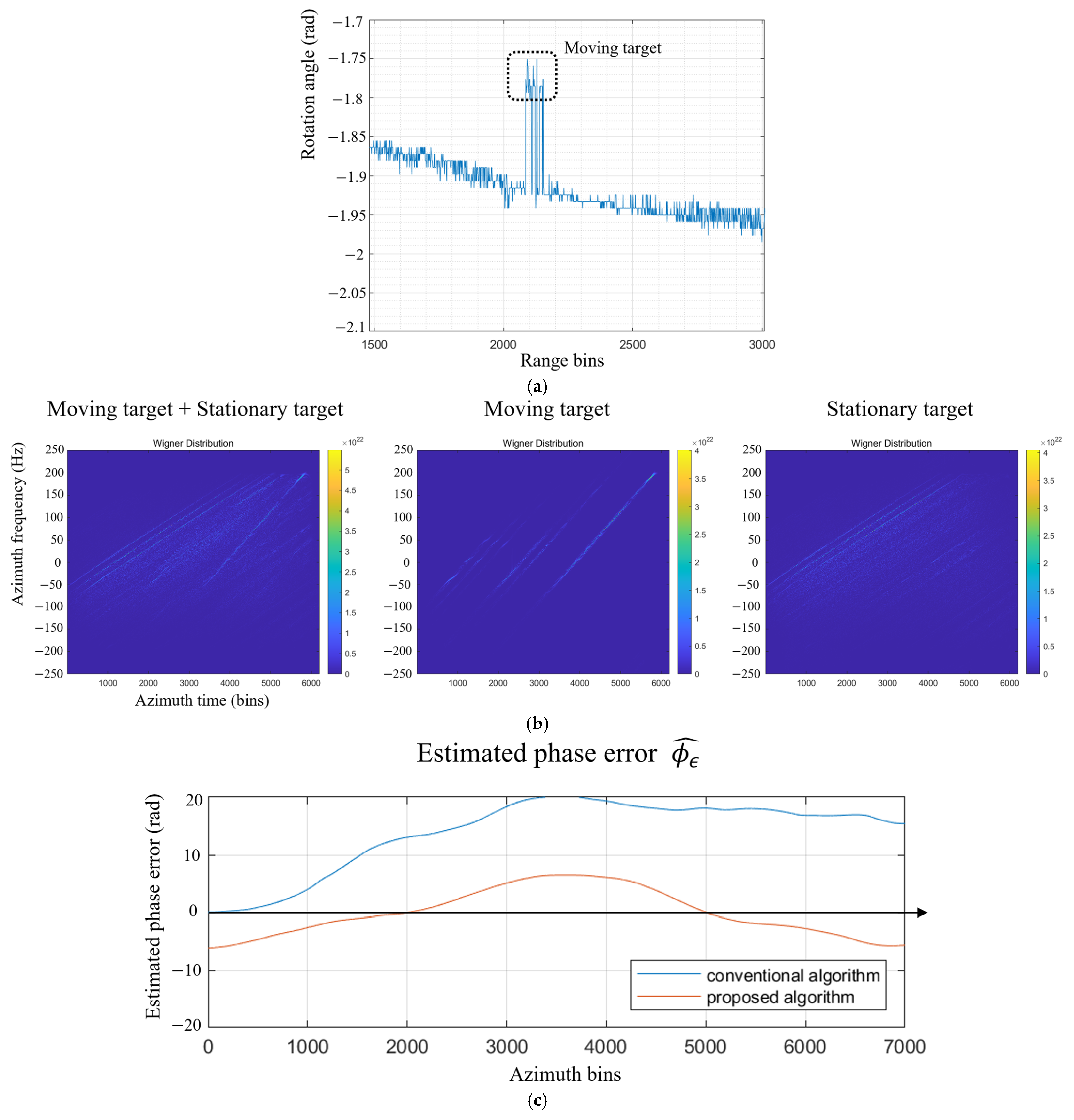
Finding moving targets: If moving targets are present, they can be detected based on the FrFT-based approach in Section 2.2. As illustrated in Figure 6a, the specific rotation angles at which the maximum peak power occurs differ from those of stationary targets, allowing for the detection of moving targets. Additionally, the specific rotation angle at which the moving target signal exhibits peak power can be identified.
(3)
Filtering moving target in FrFD: Moving target filtering is performed at the specific rotation angles identified in Step 2. This process minimizes the loss of surrounding stationary signals while effectively isolating the moving targets. Figure 6b shows the moving target extraction process and result. Through these two steps, the moving targets are detected and extracted, resulting in an equivalent image-domain signal free of moving target interference.
(4)
Circular shifting
(5)
Widowing
(6)
Phase error estimation and compensation: In conventional methods, the presence of moving targets introduces additional phase errors, leading to highly inaccurate phase error estimation. In contrast, the proposed algorithm effectively removes the moving targets, allowing for more precise autofocusing. Figure 6c compares the phase error estimated in the first iteration. It demonstrates that the additional phase error caused by the moving target was effectively managed in the previous stage.
(7)
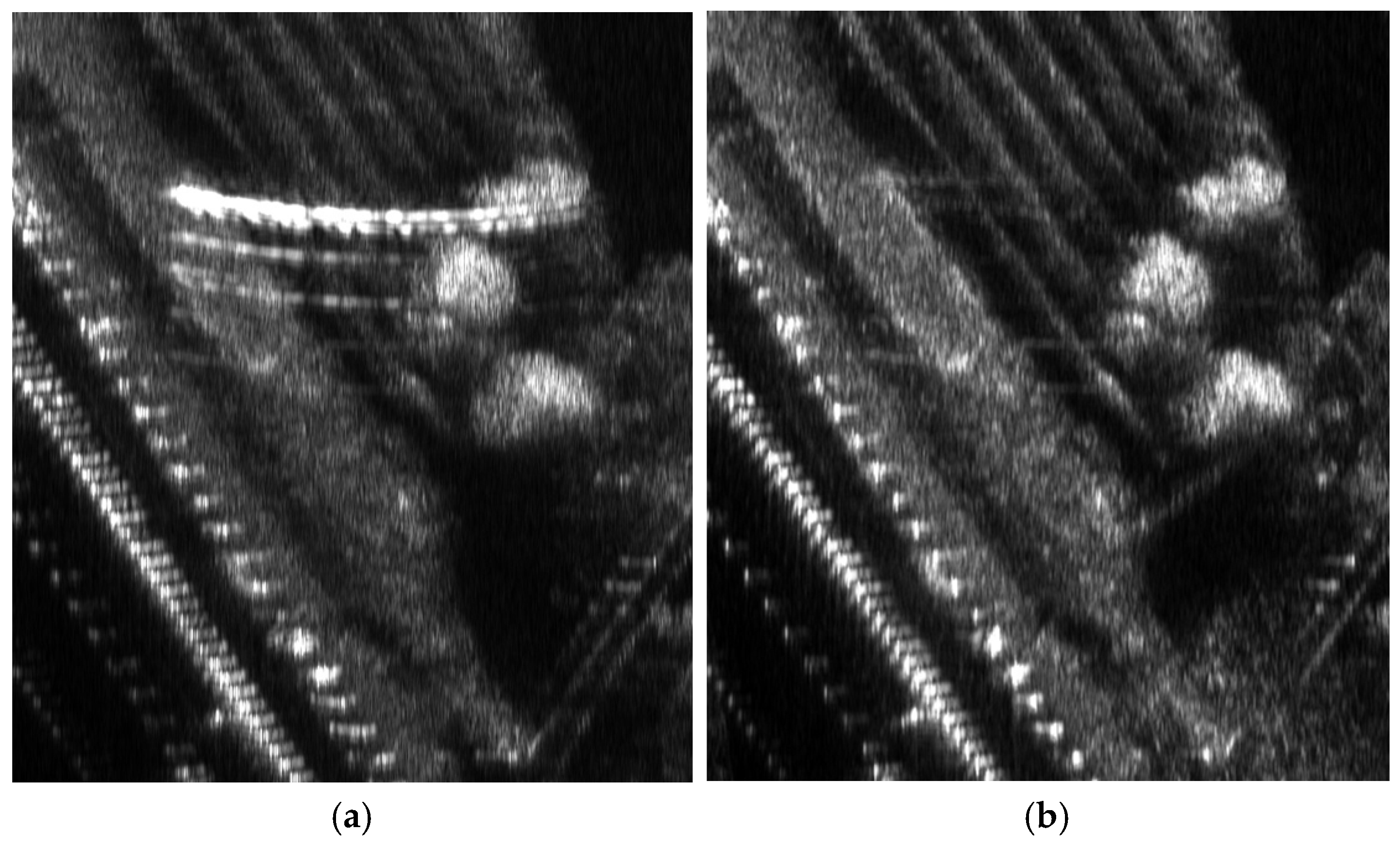
Final image: Figure 7 presents the final autofocused image obtained using the proposed algorithm. The proposed algorithm effectively eliminates the moving targets, enhancing remote sensing capabilities.

4. Conclusions

In this paper, we proposed an enhanced phase gradient autofocusing (PGA) algorithm based on the fractional Fourier transform (FrFT). The proposed FrFT-based PGA method effectively extracts and compensates for phase errors, leading to superior autofocusing performance compared to conventional PGA techniques. By leveraging the FrFT domain, our method enables better separation of desired targets from surrounding interference and enhances phase correction accuracy, ensuring high-resolution SAR imaging in dynamic environments. Additionally, the proposed method demonstrates significant advantages in moving target detection and extraction. The ability to distinguish and remove moving target-induced phase errors improves the accuracy of phase error estimation and autofocusing performance. Experimental results using real SAR data from the X-band system validate the effectiveness of our approach. Furthermore, the proposed technique exhibits strong adaptability for post-processing in various SAR-based applications, making it applicable to a wide range of operational scenarios. Real-time implementation and optimization for onboard SAR processing units will be explored to further enhance its practical applicability in next-generation radar systems.

Author Contributions

Conceptualization, K.S.; methodology, K.S.; software, K.S.; validation, K.S., Y.K. and C.K.K.; formal analysis, K.S. and Y.K.; investigation, K.S.; resources, C.K.K.; data curation, Y.K.; writing—original draft preparation, K.S.; writing—review and editing, K.S. and Y.K.; visualization, K.S. and Y.K.; supervision, C.K.K.; project administration, C.K.K. All authors have read and agreed to the published version of the manuscript.

Funding

This research received no external funding.

Data Availability Statement

No new data were created or analyzed in this study. Data sharing is not applicable to this article.

Acknowledgments

All experimental tests for verifying the proposed algorithm were conducted using data provided by the Microwave and Antenna Laboratory (MALAB) and Satellite Technology Research Center (SaTReC) at the Korea Advanced Institute of Science and Technology (KAIST). We would like to express our sincere gratitude to this institution for providing the data, which played a crucial role in enabling the advancement of our research.

Conflicts of Interest

The authors declare no conflict of interest.

References

  1. Cumming, I.G.; Wong, F.H. Digital Processing of Synthetic Aperture Radar Data; Artech House Inc.: London, UK, 2005. [Google Scholar]
  2. Roh, C.-G.; Kim, J.; Im, I.-J. Analysis of Impact of Rain Conditions on ADAS. Sensors 2020, 20, 6720. [Google Scholar] [CrossRef] [PubMed]
  3. Argenti, F.; Lapini, A.; Bianchi, T.; Alparone, L. A Tutorial on Speckle Reduction in Synthetic Aperture Radar Images. IEEE Geosci. Remote Sens. Mag. 2013, 1, 6–35. [Google Scholar] [CrossRef]
  4. Fienup, J.R. Phase Error Correction by Shear Averaging. In Signal Recovery and Synthesis III; Technical Digest Series; Optica Publishing Group: Washington, DC, USA, 1989. [Google Scholar]
  5. Kim, J.-W.; Kim, Y.-D.; Yeo, T.-D.; Khang, S.-T.; Yu, J.-W. Fast Fourier-Domain Optimization Using Hybrid L1−/L p-Norm for Autofocus in Airborne SAR Imaging. IEEE Trans. Geosci. Remote Sens. 2019, 57, 7934–7954. [Google Scholar] [CrossRef]
  6. Wahl, D.E.; Eichel, P.H.; Ghiglia, D.C.; Jakowatz, C.V. Phase gradient autofocus-a robust tool for high resolution SAR phase correction. IEEE Trans. Aerosp. Electron. Syst. 1994, 30, 827–835. [Google Scholar]
  7. Callow, H.J.; Hayes, M.P.; Gough, P.T. Stripmap phase gradient autofocus. In Proceedings of the Oceans 2003. Celebrating the Past... Teaming Toward the Future (IEEE Cat. No.03CH37492), San Diego, CA, USA, 22–26 September 2003; pp. 2414–2421. [Google Scholar]
  8. Luo, C.; Liang, Y.; Gao, J.; Lei, G.; Han, C. A Scene-Adaptive Phase Gradient Autofocus Algorithm. Remote Sens. 2025, 17, 260. [Google Scholar] [CrossRef]
  9. Chan, H.L.; Yeo, T.S. Noniterative quality phase-gradient autofocus (QPGA) algorithm for spotlight SAR imagery. IEEE Trans. Geosci. Remote Sens. 1998, 36, 1531–1539. [Google Scholar] [CrossRef]
  10. Li, Y.; O’Young, S. Kalman Filter Disciplined Phase Gradient Autofocus for Stripmap SAR. IEEE Trans. Geosci. Remote Sens. 2020, 58, 6298–6308. [Google Scholar] [CrossRef]
  11. Almeida, L.B. The fractional Fourier transform and time-frequency representations. IEEE Trans. Signal Process. 1994, 42, 3084–3091. [Google Scholar] [CrossRef]
  12. Namias, V. The Fractional Order Fourier Transform and its Application to Quantum Mechanics. IMA J. Appl. Math. 1980, 25, 241–265. [Google Scholar]
  13. Lu, Q.; Wang, K.; Liu, X. Improved SAR imaging algorithm using FRFT. In Proceedings of the 2016 CIE International Conference on Radar (RADAR), Guangzhou, China, 10–13 October 2016; pp. 1–4. [Google Scholar]
  14. Kim, C.K.; Park, M.Y.; Shin, G.H.; Park, S.O. An Improved Technique for Single-Channel Video-SAR Based on Fractional Fourier Transform. IEEE Trans. Aerosp. Electron. Syst. 2022, 58, 4044–4052. [Google Scholar]
  15. Feng, L.; HuiFa; Ran, T.; Yue, W. Research on resolution between multi-component LFM signals in the fractional Fourier domain. Sci. China Inf. Sci. 2012, 55, 1301–1312. [Google Scholar]
  16. Wahl, D.E.; Jakowatz, C.V.; Thompson, P.A.; Ghiglia, D.C. New approach to strip-map SAR autofocus. In Proceedings of the IEEE 6th Digit. Signal Process Workshop, Yosemite National Park, CA, USA, 2–5 October 1994; pp. 53–56. [Google Scholar] [CrossRef]
  17. Thompson, D.G.; Bates, J.S.; Arnold, D.V. Extending the phase gradient autofocus algorithm for low-altitude stripmap mode SAR. In Proceedings of the IEEE Radar Conference. Radar Into Next Millenn. (Cat. No.99ch36249), Waltham, MA, USA, 22 April 1999; pp. 36–40. [Google Scholar]
  18. Zhou, F.; Wu, R.; Xing, M.; Bao, Z. Approach for single channel SAR ground moving target imaging and motion parameter estimation. IET Radar Sonar Navig. 2007, 1, 59–66. [Google Scholar] [CrossRef]
  19. Perry, R.P.; DiPietro, R.C.; Fante, R.L. SAR imaging of moving targets. IEEE Trans. Aerosp. Electron. Syst. 2002, 35, 188–200. [Google Scholar] [CrossRef]
  20. Ozaktas, H.M.; Barshan, B.; Mendlovic, D.; Onural, L. Convolution, filtering, and multiplexing in fractional Fourier domains and their relation to chirp and wavelet transforms. J. Opt. Soc. Am. A 1994, 11, 547–559. [Google Scholar] [CrossRef]
  21. Zhu, S.; Liao, G.; Qu, Y.; Zhou, Z.; Liu, X. Ground Moving Targets Imaging Algorithm for Synthetic Aperture Radar. IEEE Trans. Geosci. Remote Sens. 2011, 49, 462–477. [Google Scholar] [CrossRef]
Figure 1. Flowchart of (a) the conventional PGA algorithm process; (b) the proposed FrFT-PGA algorithm process.
Remotesensing 17 01216 g001
Figure 2. Signal transformation in PGA and FrFT-based switching method: (a) equivalent signal construction in stripmap mode using PGA; (b) FrFT-based direct transformation for enhanced resolution.
Remotesensing 17 01216 g002
Figure 3. FrFT process and its application: (a) representation of the FrFD in the time–frequency plane; (b) distinguishing moving and stationary targets using FrFT-based rotation angle analysis.
Remotesensing 17 01216 g003
Figure 4. Phase error estimation and compensation performance: (a) iterative phase error estimation process; (b) estimated phase error comparison at the 11th iteration.
Remotesensing 17 01216 g004
Figure 5. The final image (a) before phase error compensation and (b) after phase error compensation.
Remotesensing 17 01216 g005
Figure 6. Moving target detection and phase error estimation in FrFT-based processing: (a) detection of moving targets using rotation angle analysis in the FrFD; (b) moving target filtering in the FrFD; (c) comparison of estimated phase error.
Remotesensing 17 01216 g006
Figure 7. The final image (a) before phase error compensation and (b) after moving target extraction and phase error compensation.
Remotesensing 17 01216 g007
Table 1. System parameters of the experimental X-band SAR setup.
System ParameterValue
Radar platformAutomobile
Platform velocity21~22 m/s
Operating modeStrip-map, Pulsed radar
Squint angle 0 °
Observation height60 m
PolarizationSingle-Pol (Linear)
Center frequencyX-band
Table 2. Comparison of phase error range reduction over iterations between the proposed and conventional algorithms.
Proposed AlgorithmConventional Algorithm
IterationPhase Error Range (Rad)IterationPhase Error Range (Rad)
Initial11.9321Initial12.5213
13.322614.7070
2~80.2294~2.07532~80.3300~1.9135
90.149590.3541
100.3575100.3078
110.0931110.4054
120.0747120.3505
--13~210.2015~0.4307
(Mean: 0.3225)
--220.3708
--230.3377
--240.2618
--250.1918
--260.1396
--270.1057
--280.0769
Disclaimer/Publisher’s Note: The statements, opinions and data contained in all publications are solely those of the individual author(s) and contributor(s) and not of MDPI and/or the editor(s). MDPI and/or the editor(s) disclaim responsibility for any injury to people or property resulting from any ideas, methods, instructions or products referred to in the content.

