Review

Evolution of Spaceborne SAR Missions in Earth Orbit

Dipartimento di Ingegneria, Università degli Studi della Campania “Luigi Vanvitelli”, 81031 Aversa (Ce), Italy
Remote Sens. 2025, 17(22), 3773; https://doi.org/10.3390/rs17223773
Submission received: 30 September 2025 / Revised: 6 November 2025 / Accepted: 18 November 2025 / Published: 20 November 2025

Highlights

  • What are the main findings?
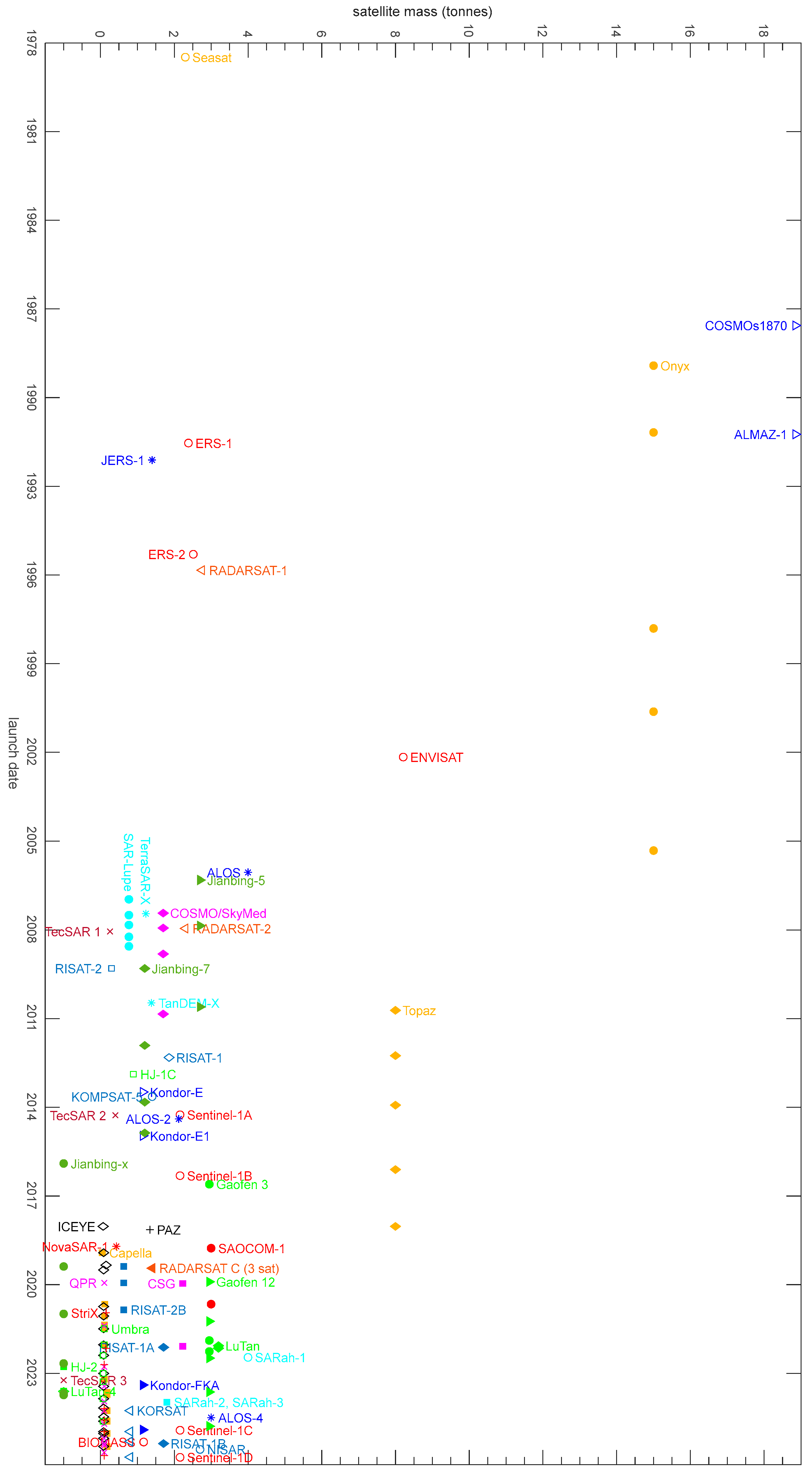
  • Since 1978 and until 4 July 2025, 200 SAR satellites have been launched, which can be roughly grouped into four broad categories depending on bus dimension and SAR antenna type. The number of SAR satellites has grown exponentially, with 16 satellites launched from 1978 to 2006, 41 from 2007 and 2018, 34 from 2019 to 2021 and 109 from 2022.
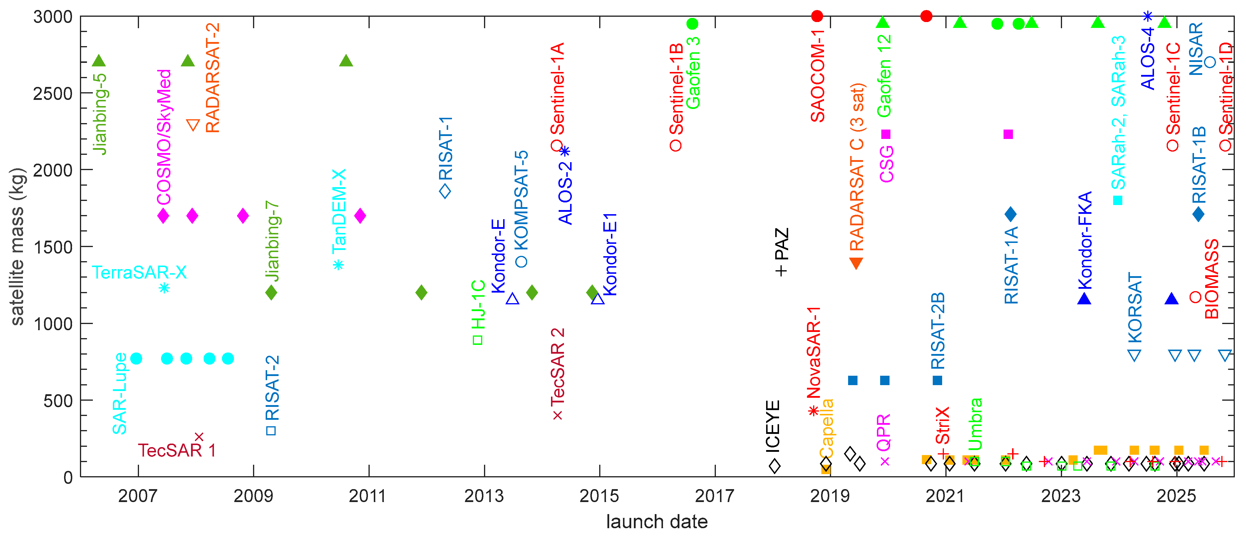
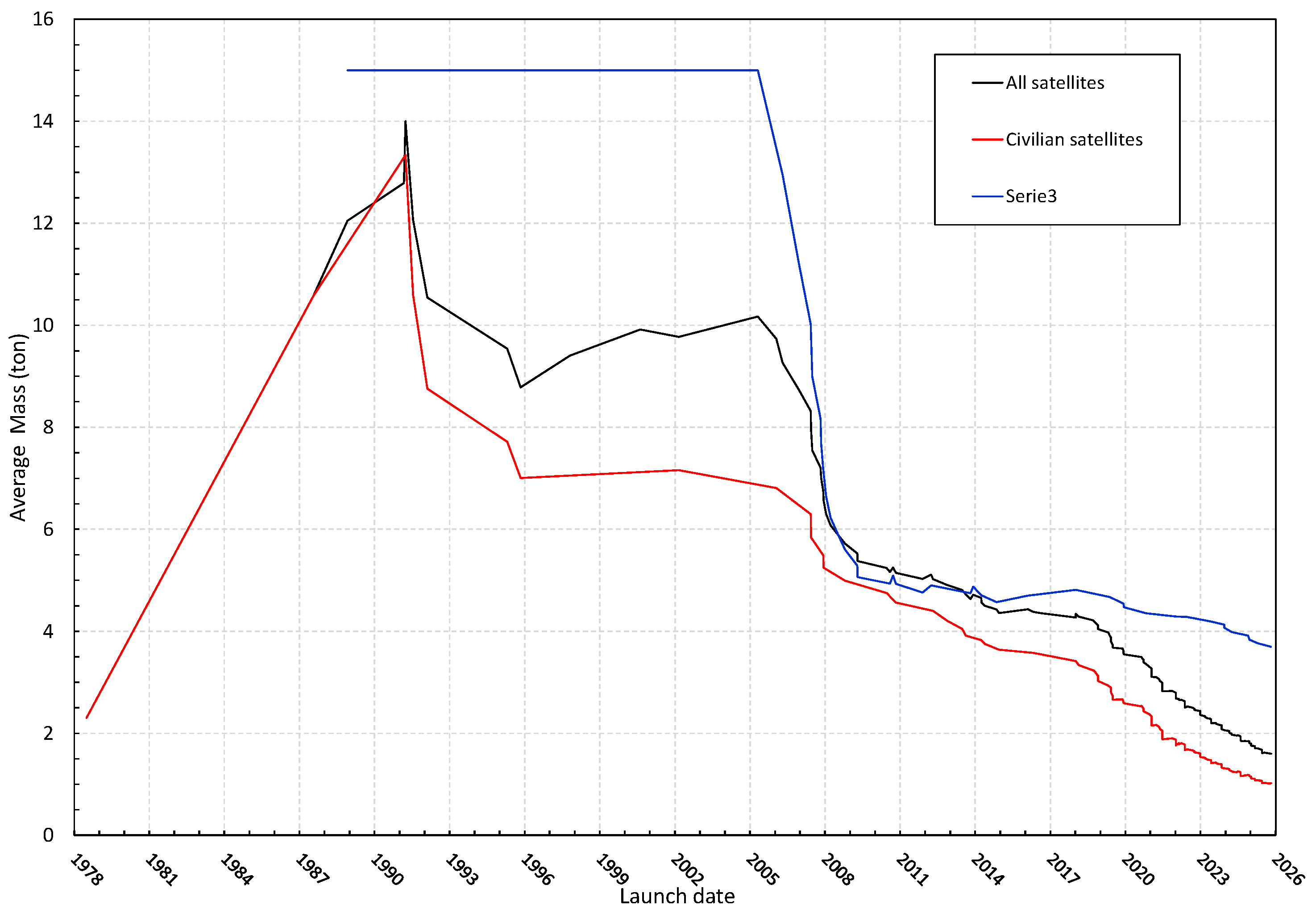
  • The average mass of SAR satellites is 1025 kg (3697 kg) for civilian (military) satellites and it has been rapidly decreasing for the last twenty years. Mass reduction is currently supported by the large number of launched SAR microsatellites, the newest category among the four.
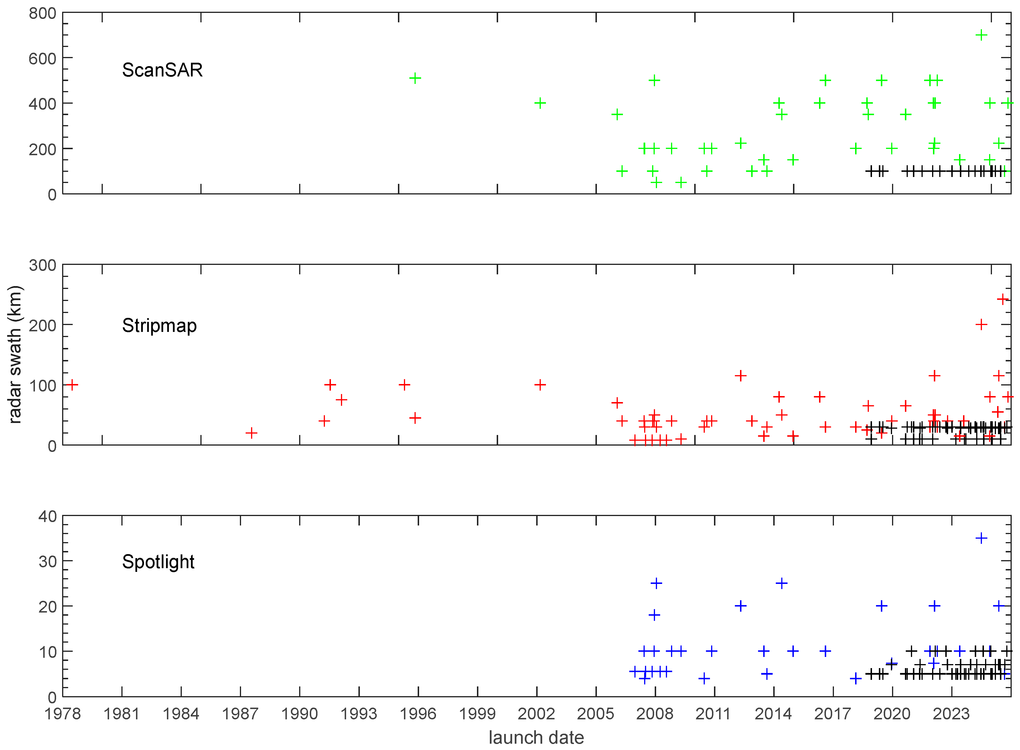
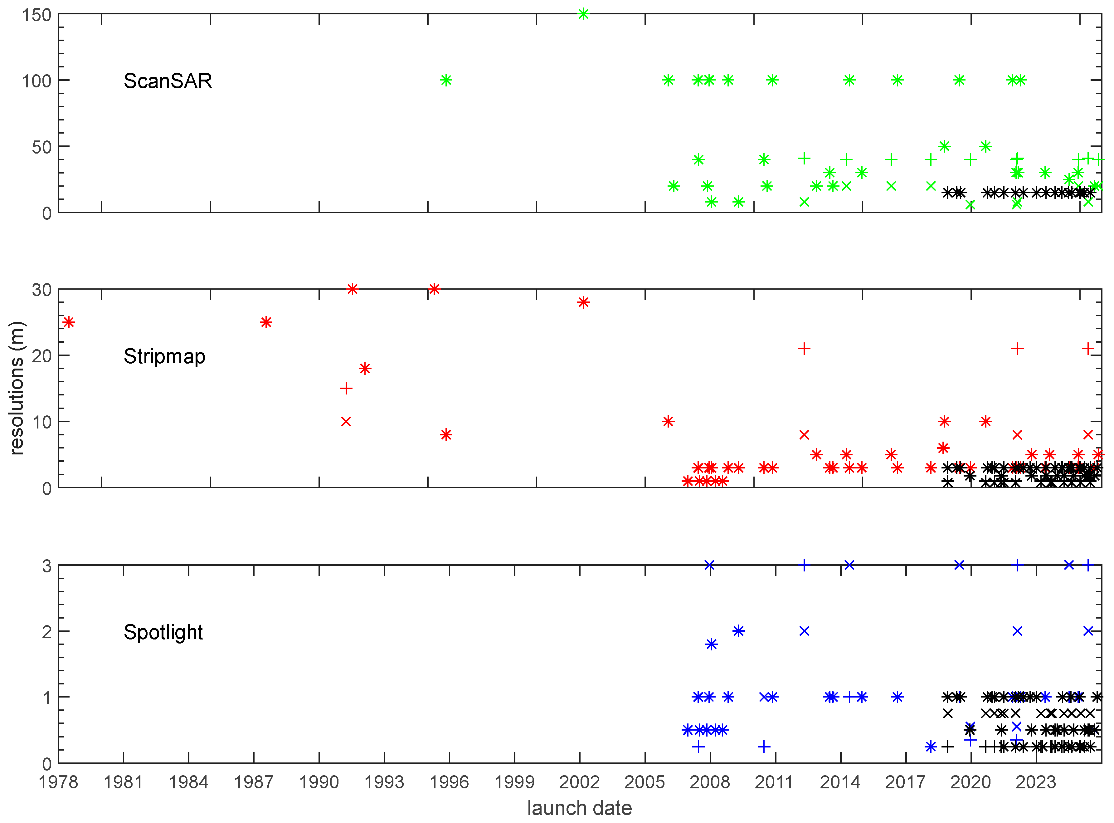
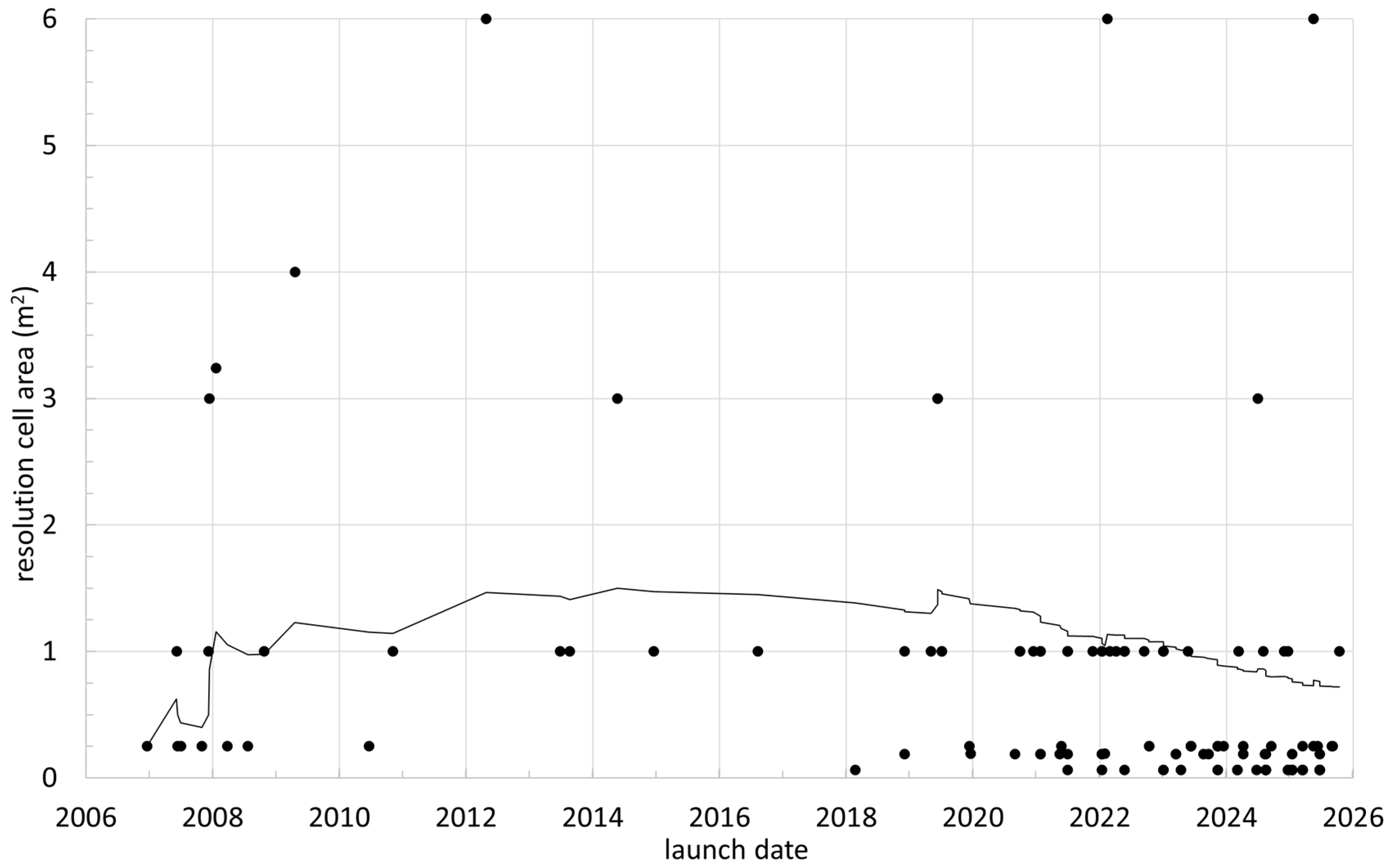
  • SAR resolutions have evolved from a few tens of meters to the meter level in Stripmap mode, from the meter to the submeter level in Spotlight mode, and from the hundreds of meters level to a few tens of meters in ScanSAR mode.
  • What is the implication of the main finding?
  • Future satellite missions will be based on classical SAR satellites, with masses of 1–2 tonnes and a large rectangular active phased array antenna. They have large swaths and high resolution and can also fulfill the needs of many applications thanks to a variety of polarimetric capabilities. In addition, the SAR microsatellite family, started with Capella and ICEYE programs, strengthened with QPR, Umbra and StriX constellations, are likely to continue their development with new constellations (e.g., IRIDE). They can fulfill the applications which require frequent data updates thanks to the constellation approach.
  • Applications will likely arise that can benefit from synergies between both approaches to SAR missions.

Abstract

A truly operational SAR was first flown in space in 1978 on board the Seasat satellite. Since then, its utilization first expanded to Canada, Europe and Japan, and then to countries with emerging space industries later on. Many technological developments have been crucial in the evolution of SAR missions. The introduction of active phased array antennas enabled a variety of operation modes and expanded SAR data applications. Miniaturization of satellite technology allowed for a paradigm change in SAR mission development with the use of small and micro satellites in lieu of large spacecraft. The paper reviews 47 years of SAR missions in low Earth orbit and highlights evolution trends by analyzing 200 satellites.

1. Introduction

The first ideas of Synthetic Aperture Radar (SAR) were developed by Wiley in the 1950s [1], who made use of signals generated by an airborne radar. Those signals were processed with a novel technique, named Doppler-beam sharpening, able to attain high spatial resolution in the direction of flight. In the same years, other experimental studies were conducted independently at the University of Illinois, also showing capability to improve resolution [2]. The wording “synthetic aperture” was instead introduced at the University of Michigan during the development of the Project Michigan, started in 1953 [3].
A typical airborne radar is equipped with a rectangular antenna with a length much longer than the width. Since the radar transmits a pulse with a linearly increasing frequency (chirp), a high range resolution (in the elevation direction) can be synthesized depending on the transmitted bandwidth. The intuition of the Doppler sharpening approach is that a potential bandwidth also exists in the azimuth direction thanks to the observation geometry. The Doppler bandwidth can be reconstructed to synthetize a high azimuth resolution provided that it is adequately sampled by operating the radar several times (with an adequate PRF) during its flight over the target area. From another point of view, each pulse samples the Fourier transform of the target reflectivity function, depending on the observation direction. Thus, the target reflectivity function can be evaluated as the inverse Fourier transform of all range-compressed and frequency-converted signals. With the first approach, the range–Doppler algorithm was conceived to generate SAR images, while the latter approach is the basis for the omega-k algorithm. References [4,5,6,7] give further insights into SAR interpretation and processing.
After almost three decades of development and operation of airborne SARs and the experimental military program QUILL [8], the USA launched the first truly operational spaceborne SAR on board the Seasat satellite [9,10] in 1978. Seasat was a large satellite, with a mass of 1.8 tonnes and a multi-sensor approach. The microwave segment of the payload integrated a scanning radiometer, a scatterometer, a radar altimeter, and an L-band (23.5 cm) SAR. The Seasat SAR demonstrated great performance but, unfortunately, a failure in the electrical power subsystem ended the mission after only three months of operation. This fact generated the conspiracy theory that the mission was terminated for national security reasons. While the USA continued to develop SAR technology on board the Space Shuttle, Canada, the European Union, Japan and the USSR started their own spaceborne SAR programs [11], developing large satellites which were launched in the 1990s. Emerging nations have then joined SAR development.
New ideas and concepts have been arising worldwide since the late 1990s thanks to the miniaturization achieved in satellite technology and to advances in specialized fields such as onboard processing, inter-satellite links, and satellite relative navigation. They rely on smaller satellites operating in multi-satellite systems, either in constellation or as distributed radar systems [12].
Although SAR have also been operated around other planets by the USA (Pioneer Venus [13] and Magellan [14] to Venus, Cassini to Titan [15]) and the USSR (Venera 15 and 16 to Venus [16]), this review paper will only focus on Earth-orbiting missions. A detailed description of all missions is presented in Section 2 with a historical perspective. Then, trends and developments are analyzed and highlighted in Section 3.

2. SAR Mission Overview

2.1. First SAR Satellite and SAR Program in USA

2.1.1. Seasat

The USA launched the first operational SAR satellite ever [9] on 27 June 1978, on Atlas-F/Agena from Vandenberg Air Force Base, California into an almost-circular Low Earth Orbit (LEO) at a mean altitude of about 787 km and an inclination of 108°. Contrary to most successive SAR missions, the orbit was not sun-synchronous, although it was a repetitive orbit with a repeat cycle of 17 days.
The Seasat mission had been being designed at Jet Propulsion Laboratory since 1972 as an experimental mission to demonstrate the potential of spaceborne imaging radars for Earth study. Its main objectives were related to sea ice study (extension, edge, thickness) and the foreseen measurements were glacier and sea ice cover, sea ice temperature and classification of sea ice types. In addition, Seasat was intended as a proof-of-concept for global monitoring of oceanographic phenomena.
Seasat was a large spacecraft developed by Lockheed Missiles and Space Company, Bethesda, MD, USA and Ball Aerospace Systems, Boulder, CO, USA. It was based on the Agena upper stage to provide bus services (electric power, telemetry, attitude control, command and control) and a payload module with a multi-sensor package including a scatterometer, an imaging multi-spectral radiometer (vis/IR), an imaging multi-spectral passive microwave radiometer, a radar altimeter and an SAR. The Seasat spacecraft had an overall mass of about 2.3 tonnes and delivered a power of 1 kW at beginning of life (BOL).
The satellite orbited for 105 days until early October 1978, when a power failure terminated the mission. Payloads were operated for 70 days and SAR data acquisition lasted for about 42 h. Despite its short lifetime, the Seasat SAR demonstrated sensitivity to surface roughness, slope and land–water boundaries. It was successful in retrieving several data sets, such as ocean waves spectra, surface features caused by internal waves, motion of polar ice, etc. Seasat SAR [10] was designed to operate in L band (23.5 cm) at a ground resolution of tens of meters. Similarly to most first-generation spaceborne SARs, the radar operated at a single elevation angle, polarization, swath width and resolution (Table 1).

2.1.2. Shuttle Imaging Radar Program

After Seasat, NASA abandoned the free-flying satellite-based SAR programs. Rather, they designed, developed and operated SAR payloads on board the Space Shuttle. The Space Shuttle offered the capability to fly large mass payloads for short missions and to return the payload to the ground. Therefore, it was preferred to satellites because it guaranteed hardware reuse, hardware updates, and the possibility of gradually developing complex radars. The Shuttle Imaging Radar (SIR) program realized three payloads and operated five missions.
SIR-A was the first SIR mission [17], flown for 3 days in November 1981 at an altitude of about 225 km during the second Shuttle flight (STS-2). The SIR-A payload [18] was derived by spare parts of Seasat SAR. The antenna (mass 181 kg) was supplied by an electronics module (1.5 m × 1 m × 25 cm, 136 kg) including a transmitter, a receiver, a calibrator and a control computer. The SAR electronics were coupled with cold plates and mounted on the pallet. SIR-A aimed to demonstrate the Shuttle’s capability to provide useful data products within the constraints of the STS-2 mission and to assess the Shuttle performance as a scientific platform for Earth observations.
SIR-B [18,19] was the second SIR experiment. It was flown in October 1984 (STS-41G) for one week and the radar operated at three different altitudes: 225 km, 272 km, 352 km. The payload was an upgraded version of SIR-A (Table 1), with a longer antenna, different range resolutions and different swath widths. SIR-B was the first radar able to mechanically steer its antenna beam in elevation. SIR-B was aimed at demonstrating the usefulness of remote sensing of the Earth. In addition, it was expected to enhance the comprehension of the Earth environment thanks to surface and atmospheric data. Unfortunately, the mission was affected by many communication problems and SIR-B collected data for 7.5 h only (20% of expected data delivery).
SIR-C [20,21], the evolution of SIR-A and SIR-B, was characterized by multi-polarization and multi-frequency capabilities. A new fully polarized radar in C-band (≈5.6 cm) was developed, and the original L-band (≈24 cm) radar was also upgraded to allow for full polarimetric data acquisitions. SIR-C has been the only multi-frequency SAR to be operated from space for decades, until the launch of NISAR (see Section 2.11.3) in July 2025. The SIR-C antenna was a great technological step with respect to previous radars. Several low-power solid-state transmitters were distributed across the antenna, forming an active phased-array antenna. The new antenna technology enabled efficiency improvement by a factor of eight and allowed for electronic beam steering in the elevation direction. In addition, thanks to the beam steering capability, a ScanSAR mode was demonstrated, improving swath width by degrading azimuth resolution.
Thanks to a collaboration with Germany (DARA/Dornier) and Italy (ASI/Alenia Spazio), the SIR-C payload was complemented with a third radar in the X-band (3.1 cm): X-SAR [22] operated a 12 m × 0.4 m slotted wave-guide antenna in single (VV) polarization and resolutions of 25 m (azimuth) and 20 m (range). SIR-C/X-SAR was flown twice on 11-day Shuttle missions: SRL-1 (STS-59) on 9 April 1994, and SRL-2 (STS-68) on 30 September 1994. During the second flight, the orbiter was flown in nearly the same orbit, enabling the mission to perform repeat-pass SAR interferometry at all frequencies. Elevation and change detection studies were then conducted.
The Shuttle Radar Topography Mission (SRTM) [23,24] was later flown utilizing a modified SIR-C/X-SAR payload. C- and X-band receiving antennas were replicated and separated by a 60 m long rigid boom from the transmitting/receiving antennas located on the Shuttle. The first single pass SAR interferometer was thus conceived. SRTM is still the first and unique single-pass spaceborne SAR interferometer system with dual frequency, dual polarization and ScanSAR mode capabilities. The total mass of the SRTM payload was 14,500 kg.
The SRTM mission objective [24] was the derivation of a Digital Elevation Model (DEM) with coverage of the Earth’s land surfaces between the latitudes of −54° and +60°, (80% of the land masses) for applications in studies on flooding, erosion, landslide hazards and earthquakes. SRTM DEM meets ITHD-2 (Interferometric Terrain Height Data -2) specifications: 30 m × 30 m pixel, 16 m absolute vertical linear accuracy (90%), 20 m absolute horizontal radial accuracy (90%). SRTM was launched on 11 February 2000, on board STS-99. It was operated for 11 days on a circular repeat orbit (altitude 233 km, inclination 57°).

2.1.3. US Military SAR Missions

For completeness, US military space SAR missions are also introduced, although useful information from the radar point-of-view (frequency, resolutions, operational modes, etc.) is unavailable. The US military were the first to experiment with spaceborne SAR with their Project QUILL satellite [8]. QUILL was launched on a Lockheed AGENA D launcher and the launcher upper stage was utilized as a satellite.
KP-II SAR was operated at an altitude of about 240 km from the launch on 21 December 1964, to the satellite reentry on 11 January 1965. This project remained classified until 2012, but it did produce the first ever SAR images from orbit, achieving resolutions of about 2.3 m (azimuth) and 24 m (range).
The Lacrosse/Onyx Program [25,26,27] is a series of terrestrial radar imaging reconnaissance satellites operated by the United States National Reconnaissance Office (NRO), which were officially unveiled in 2008 when NRO declassified its SAR satellite constellation. Lockheed Martin built five Onyx satellites with a design lifetime of 9 years and a mass ranging between 14.5 and 16 tonnes. They were launched and operated in low elliptical prograde orbits with inclinations of either 57° or 68°. Onyx 1 was launched by Space Shuttle in 1988, while Onyx 2 to 5 were launched by Titan IV in 1991, 1997, 2000 and 2005, respectively.
The follow-up of the Onyx program was the Future Imagery Architecture (FIA), an integrated optical and radar spaceborne system for surveillance. In 2005 the optical section was canceled due to technological issues and a huge cost rise. Boeing only developed five Topaz satellites [28] of about 8 tonnes, the radar component of FIA. Topaz satellites have been launched in 2010, 2012, 2013, 2016 and 2018 by Atlas V and Delta IV at altitudes of about 1100 km and inclinations of about 120°.
The National Reconnaissance Office (NRO) is developing lower mass spacecraft to be operated in a constellation of hundreds of satellites. The Proliferated Architecture Mission [29] has been providing intelligence, surveillance and reconnaissance information since 2024. It is likely that radar payloads are also deployed, although no confirmation was found in the literature.

2.2. European SAR Program

2.2.1. ERS-1 and ERS-2

The ERS-1 (Earth Remote Sensing) satellite was the first European SAR satellite [30]. It was launched on 17 July 1991, on an Ariane-4 vehicle from Kourou, French Guiana. ERS-2 [31] was the follow-up mission, with the same radar payload and an almost identical satellite. ERS-1 was operated until 10 March 2000, when a failure in the attitude control system terminated the mission. Its lifetime of about 8.5 years greatly exceeded the 2-year design lifetime. The launch of ERS-2 was delayed until 21 April 1995, and the mission ended on 5 September 2011. Thus ERS-1/ERS-2 guaranteed data continuity for two decades and the availability of two orbiting SARs for almost 5 years, which gave the opportunity to implement tandem missions (Section 2.2.3).
The ERS satellites were designed as multi-disciplinary missions to advance knowledge of the environment on a global scale [32]. Their main goals were related to the marine environment: to improve the models of the interaction between oceans and atmosphere; to improve understanding of ocean circulation; to attain reliable mass balance of polar ice sheets; and to monitor coastal processes and pollution. Additionally, the missions had the goal of advancing the detection of changes in land use. The ultimate goal of the ERS program was to contribute to the understanding of the greenhouse effect, improving global warming comprehension to the end of obtaining a reliable estimate of expected sea level rise. Ref. [32] provides a detailed description of ERS’s contribution on different remote sensing applications.
ERS-1 and ERS-2 were launched on the same sun-synchronous low Earth orbit at the altitude of 785 km and inclination of 98.5°, with an ascending node local time (LTAN) of 10:30 am. The repetitive operational orbit had a 35-day repeat cycle, designed to achieve global coverage and almost double coverage from medium to high latitudes.
The ERS payload was developed as a multi-sensor package [33] to meet such challenging mission requirements. The microwave payload comprises a radar altimeter, a radiometer, a scatterometer and an SAR. In particular, the wind scatterometer and the C-band (≈5.6 cm) SAR were part of the Active Microwave Instrument (AMI), whose electronics could feed either the SAR antenna or the three-antenna system of the scatterometer (wind-mode). SAR [34] was designed to operate either in wave-mode or in image-mode and it supported a single polarization (LV). The image-mode duty cycle was 12 min per orbit (12%) for a 4.8 kW peak power. The 10 m × 1 m antenna was designed to attain 30 m spatial resolution on a 100 km swath with a 23° off-nadir angle.
The ERS spacecraft design was innovative for the period and derived from the French SPOT bus [30,33]. It was based on two different modules: the spacecraft segment, providing all satellite functions in a modular way, and the payload segment integrating all the payloads. The spacecraft mass was 2384 kg, with the payload accounting for a ton, and the peak power of 2.6 kW provided by a deployable 11.7 m × 2.4 m solar array and 96 Ah NicCd battery on a 30 V unregulated power bus. The three-axis-stabilized attitude control system was able to achieve 0.1° (pitch/roll) and 0.2° (yaw) pointing accuracies. Attitude sensing was attained by integrating an infrared horizon sensor, a narrow-field sun sensor, two wide-field sun sensors and a 3-gyroscopes inertial platform. Stabilization was provided by a set of momentum wheels and magneto-torquers for desaturation.
Spacecraft propulsion was based on monopropellant thrusters aligned with the spacecraft axes. They provided orbit control and attitude control in non-nominal mission phases. ERS-1 carried 300 kg of hydrazine.

2.2.2. Envisat

In 1990, ESA planned to develop a single satellite for both operational meteorology and remote sensing: the Polar Platform. After three years, the Polar Platform program was canceled [35] and substituted by two different satellite missions: MetOpSat (Meteorological Operational Satellite) and Envisat (Environmental Satellite). Thus, Envisat is the second-generation ESA Earth observation satellite, after the ERS ones. Envisat represented significant advancements from both the platform and the payload points of view. Envisat was launched on 1 March 2002, on Ariane-5 from Kourou in French Guiana [36]. Its mission suddenly ended on 8 April 2012, when its lifetime had greatly exceeded the nominal 5 years. For 9 years Envisat and ERS-2 were both in operation, which again allowed tandem missions (Section 2.2.3).
Envisat’s mission objectives were to provide an assessment of Earth’s health and a great improvement of our understanding of climate change [36,37]. Thus, it was developed to support many scientific investigations in several fields: meteorology, climatology, environment, atmospheric chemistry, vegetation, hydrology, land use, ocean and ice processes. Such a broad range of requested data led to the need for a multi-sensor approach with the integration of ten instruments [38]. In the microwave frequencies, three instruments were developed: the Radar Altimeter 2 (RA-2), the Microwave Radiometer (MWR) and the C-band (≈5.6 cm) Advanced Synthetic Aperture Radar (ASAR). ASAR guaranteed continuity with ERS-1 and ERS-2 data. Due to this approach, Envisat remains the largest civilian earth observation spacecraft ever built, with its launch mass exceeding 8 tonnes.
Envisat [39] was flown on a sun-synchronous orbit at an altitude of 800 km and inclination of 98.5°, with a 35-day repeat cycle and an LTAN = 22:00. The orbit guaranteed global coverage for large swath sensors.
The Envisat ASAR [40,41] represents a great advancement with respect to the previous-generation SARs flown by ERS satellites. The 1.3 m × 10 m antenna utilized active-phased array technology, which enabled electronic beam steering and multi-polarization. Thus, different working modes were implemented, with different selectable combinations of swath width and resolutions (Table 2).
When Image Mode was selected, precision images could have spatial resolution of 30 m over a swath selectable among seven different options, whose incidence angle was selected within the available 15–45° range. Instead, Wave Mode produced 5 km × 5 km vignettes spaced by 100 km in the along-track direction.
ScanSAR technique was applied in two different working modes, depending on requested geometric resolution. Image, Wave and ScanSAR modes could be operated in single, selectable (HH or VV) polarization. In contrast, the Alternating Polarization mode produced dual polarization data, selectable between three combinations.
Envisat’s mass was 8140 kg, including about 300 kg of hydrazine and 2150 kg for the instruments. The spacecraft was composed of two major modules [39]. The Service Module, derived from the French Spot Mk-II bus, provided all standard satellite functions. Considering the high-power demand of 6.75 kW at EOL, the power source was a deployable, sun-pointing solar array integrating Si solar cells over its surface of 14 m × 5 m. Eight NiCd batteries supplied a 320 Ah capacity. Two power buses were used: an unregulated (22–37 V) and a regulated (50 V) one.
Attitude measurement was based on two two-axis gyroscopes, a digital Earth sensor, a digital Sun sensor and two star-trackers. Gyros, Earth and Sun sensors were duplicated for redundancy, while a single redundant star tracker was added. Attitude control relied on five reaction wheels and four magnetorquers for desaturation. In addition, initial attitude acquisition and safe mode were implemented with eight (duplicated) thrusters. Envisat performed a yaw steering maneuver to align its antenna x-axis with the satellite–atmosphere relative velocity with the aim of reducing satellite cross-section and orbit decay and, additionally, to attain almost zero-Doppler frequency at boresight. In addition, the spacecraft executed a combined pitch/roll maneuver (nadir pointing) to align satellite local vertical to the Earth geodetic normal.
Three-axis stabilization had the following 3 sigma performance: pointing < 0.1°, measurement: <0.03°. TT&C (Telemetry, Telecommunication and Command) relied on S-band for telemetry and command, X-band for direct downlink and Ka-band for DRS (Data Relay Satellite) downlink.

2.2.3. European Tandem Missions

ESA’s plans to replace ERS-1 with ERS-2 had to face the unforeseen longevity of ERS-1, which gave the opportunity to have two operational SAR satellites flying on the same orbit for about five years. The same opportunity came up with the couple Envisat/ERS-2 for nine years during the succeeding decade.
In 1993, the European remote sensing science community realized that a future tandem mission of ERS-1 and ERS-2 (launch planned in 1995) would have been a great opportunity for SAR interferometry experiments. Then, in 1995, ESA Council approved an ERS-1/2 tandem mission for a nominal period of 9 months which occurred after the end of the ERS-2 commissioning phase.
In the tandem configuration, both spacecraft fly in the same orbit [42], with ERS-2 following ERS-1 at an approximate delay of 30 min and retracing the ground tracks with a 24 h interval. The tandem configuration enables the double acquisition of SAR images of the same ground area at a temporal distance of 24 h, which greatly reduces time decorrelation between the image pair. For years, time decorrelation had been one of the major limitations of repeat-pass interferometry using different data sets of the same satellite. During the months of the ERS-1/ERS-2 tandem mission, 110,000 SAR data pairs were acquired [31]. South America and part of Southeast Asia had a single interferometric coverage (a single pair of SAR data for any point), whereas Europe and North America had a full, multiple interferometric coverage, with 5–6 pairs for any point.
Tandem missions had a further, deeper development with Envisat/ERS-2 [43]. A new orbit control strategy was applied [44] to greatly shorten the data delay between the two SAR acquisitions (and ground-track retracing time) from the 24 h of ERS-1/ERS-2 tandem to about 30 min. Such a reduction enables a much lower time decorrelation and, consequently, a great improvement in signal coherence [45]. Different tandem operations were implemented with the ERS-2/Envisat couple:
  • First operation: From September 2007 to February 2008 with 30 min time separation between the satellites.
  • Second operation: From November 2008 to April 2009 with 28 min time separation.
  • Third operation: From February to April 2010 with 30 min time separation, covering for the first time Antarctica’s coastal glaciers and ice shelves.
  • Fourth operation: From July to October 2010.
SAR interferometry data from ESA tandem missions were utilized to derive digital elevation models of the observed scenes [46] and to measure small movements of the Earth’s surface or Earth’s glaciers [47]. Such techniques were supported by a very good coherence of SAR data sets and an adequate knowledge of the baseline vector (distance between the two radars).

2.2.4. Sentinel-1

After the development of the ERS and Envisat missions, Europe has been developing the Copernicus program, originally named Global Monitoring for Environmental Security (GMES), since 1998 [48]. The space-based components of the systems have been developed by ESA. Copernicus represented a significant change in satellite design approach after Envisat, a very large, multi-payload spacecraft. ESA developed several Sentinel missions, each one addressing a specific operational need of Copernicus. Thus, each satellite is designed to carry a single payload with the aim of reducing mass, cost, development time and risk of a single mission.
Sentinel-1 is a polar-orbiting radar imaging mission for land and ocean services, carrying Synthetic Aperture Radar [49,50]. Its main, fast track services are marine core services, land monitoring and emergency services. Sentinel-1’s [51] specific goals are monitoring sea ice zones and the arctic environment, including oil spills; surveillance of marine environment and marine transport zones; monitoring land surface motion risks; mapping of land surfaces: forest, water and soil agriculture; and mapping in support of humanitarian aid in crisis situations (e.g., flooding, earthquakes). Unlike ERS and Envisat, which had been designed to supply data at the best possible performance, Sentinel-1 satellites are intended as operational satellites. Thus, they are required to reliably supply data according to user needs.
The mission is designed to provide radar mapping of the Earth with high revisit frequency and many years of continuity of service. Therefore, to achieve high observation frequency, it is conceived as a constellation of two satellites flying in the same orbit with a 180° in-plane separation along the orbit. In order to guarantee long-term service, additional satellites are already planned and developed to replace the flying ones at end-of-life.
Sentinel-1 spacecraft have an operational life of 7 years, but consumables are dimensioned for 12 years. They fly on a sun-synchronous, frozen orbit at the approximate altitude of 693 km and inclination of 98.2°. The orbit has a repetition period of 12 days, when 175 satellite orbits have been traced.
Sentinel-1 spacecraft are based on the PRIMA bus (TASI), a heritage of COSMO-SkyMed and RADARSAT-2 programs. It is made of three main modules [50,52], which are structurally and functionally decoupled to allow for a parallel module integration and test before satellite final integration: Service Module integrating all the bus units apart from the propulsion ones; Propulsion Module, carrying all the propulsion items connected by tubing and connectors; Payload Module, with all the payload equipment including the SAR Instrument antenna. Launch mass is 2157 kg, including 154 kg of monopropellant fuel, and average power requirement is 4.8 kW at EOL.
The nominal attitude is based on the total zero-Doppler maneuver, which is a combined yaw/pitch maneuver to guarantee zero-Doppler frequency at boresight (also compensating for the small orbit eccentricity) and to reduce antenna cross-section with respect to the atmosphere. In addition, a roll steering maneuver is also implemented and ensures constant slant range along the orbit. Attitude measurement relies on fine sun sensors, magnetometers, star trackers and a fiber optic inertial unit. Actuators consist of four reaction wheels, magnetic torquers, and four pairs of thrusters. Nominal attitude is controlled with an accuracy of 0.01°, while measurements have an accuracy of 0.003°. The electric power subsystem utilizes two solar wings of triple junction solar cells and a LiIon battery of 324 Ah. Telecommunications rely on S-band for telemetry and command and on a 600 Mbit/s X-band channel for payload data.
The Sentinel-1 payload is a C-band (≈3.6 cm) SAR [50,52] developed by EADS Astrium Germany and its 12.3 m × 0.8 m, 880 kg antenna is an active phased array able to steer the beam in both the elevation and the azimuth directions. The radar supports dual polarization (selectable between HH+HV and VV+VH) with a single transmit chain selectable between H or V and two parallel receive chains to acquire both H and V signals. The Sentinel-1 SAR operates in four modes:
  • Stripmap (continuity with ERS/Envisat) provides a 5 m × 5 m resolution over a swath width of 80 km. Swath can be selected out of six by changing beam incidence and elevation beamwidth.
  • Interferometric Wide Swath allows for a 250 km swath width at resolutions of 5 m × 20 m (3 sub-swaths are imaged by Progressive Scans SAR).
  • Extra-Wide Swath enables the acquisition of a 400 km swath width at the resolutions of 20 m × 40 m and it has been designed for maritime, ice and polar zone operational services (five sub-swaths imaged).
  • Wave mode acquires a 20 km × 20 km Stripmap image every 100 km at two alternate incidence angles to estimate direction, wavelength and heights of waves on open oceans.
Sentinel-1A was launched on 3 April 2014, and Sentinel-1B on 25 April 2016, both by a Soyuz/Fregat launcher from Kourou, French Guyana. Sentinel-1C and Sentinel-1D had been planned to replace Sentinel-1A and 1B, respectively, at their EOL and guarantee data continuity. In December 2021 Sentinel-1B had a power failure which terminated satellite life almost two years before nominal lifetime. Thus, it was replaced by Sentinel-1C, launched by Vega-C on 5 December 2024. Ariane-6 will launch Sentinel-1D on 4 November 2025.
ESA has started the development process of Sentinel 1 Nex Generation mission [53] to guarantee continuity of C-band SAR data in the next decade.

2.2.5. Biomass

ESA has been developing a very innovative SAR mission for many years which explores the P-band (70 cm) in space for the first time. Biomass [54,55] was launched on 29 April 2025 by a Vega-C launcher vehicle from Kourou. It is currently in the commissioning phase.
The Biomass mission objective is the assessment of the status and the dynamics of Earth forests by measuring their biomass and its evolution over time. For these purposes, the use of the P-band with a wavelength much longer than other conventional SARs is mandatory. The P-band enables the capability to penetrate the forest canopy and to retrieve the radar signal backscattered by trunks and branches, which constitutes the main contribution to the forest biomass.
The SAR has quad polarization and attains resolutions of 60 m (elevation) and 40 m (azimuth). The antenna consists of a feed array and a 12 m diameter deployable mesh reflector. Beam pointing is attained by spacecraft roll maneuvers. The mission is designed to gather interferometric acquisitions to perform both interferometry and tomography. The tomographic phase of the mission lasts for 18 months before the interferometric phase. The satellite is designed for a lifetime of 5 years on a sun-synchronous orbit at an altitude of about 666 km. Satellite mass is 1170 kg, including fuel for 67 kg.

2.3. Japanese SAR Program

2.3.1. JERS-1

Following the success of the US and Europe, Japan also became an early adopter of a national spaceborne SAR program. One of the main characteristics of the Japan program was the adoption and exploitation of L-band, which had been only utilized on board Seasat and SIR missions. For decades, Japan has been the only nation to orbit L-band SARs, recently joined by Argentina (see Section 2.6) and China (see Section 2.10.3).
Japanese Earth Resources Satellite (JERS-1, Fuyo-1) [56,57]—Japan’s first SAR satellite—was developed by NASDA and built by Mitsubishi Electric Co. It was an integrated Earth observation system, flying both SAR and optical sensors. JERS-1 was launched on 11 February 1992, from Tanegashima Space Center by an H-I launcher. Its nominal life was 2 years, but it remained operational until 11 October 1998, when a failure occurred. It finally reentered into the atmosphere on 3 December 2001.
JERS-1 flew on a sun-synchronous orbit at an altitude of 568 km and inclination of 97.7°, with an LTAN = 22:30 and a repeat period of 44 days. The spacecraft consisted of a parallelepipedal bus, a 3.5 m × 7 m solar array, and a SAR antenna for an overall launch mass of 1400 kg. It was three-axis-stabilized with reaction wheels and magnetic torquers, an Earth sensor, an inertial reference unit and two sun sensors.
The JERS-1 spacecraft flew both a high-resolution optical radiometer and an L-band (≈23.5 cm) SAR [58] with a single (HH) polarization. The SAR antenna consisted of eight radiating panels for an overall area of 2.2 m × 11.9 m. The radar was able to image a swath width of 75 km with off-nadir angle of 35°, achieving resolutions of 18 m in both range and azimuth directions.

2.3.2. ALOS

Advanced Land Observing Satellite (ALOS, known in Japan as Daichi) was a Japanese Earth-observation satellite, developed by JAXA and manufactured by NEC, Toshiba, and Mitsubishi Electric Corp [59,60]. Its mission objectives were cartographic mapping of land areas with 1:25,000 scale maps, environmental and hazard monitoring (within 48 h) on a global scale and resource surveying. Such objectives were met by using a multi-sensor approach [61]:
  • AVNIR-2, a four-band (visible and near-infrared) radiometer with 10 m resolution (successor of the instrument on board JERS-1).
  • PRISM, a system of three panchromatic telescopes (forward, nadir, backward).
  • PALSAR, an L-band (≈23.2 cm) SAR.
ALOS was launched from Tanegashima on 24 January 2006, by a H-IIA launch vehicle into its nominal, sun-synchronous orbit at an altitude of 691.65 km, inclination of 98.2° and LTAN = 10:30. The repeat cycle foresaw 671 orbits in 46 days. Its nominal lifetime was 3 years, but the ALOS mission ended later in May 2011 after an anomaly in power generation.
ALOS resulted in the largest Japanese spacecraft, with an envelope of 8.9 m × 27.4 m × 6.2 m and a launch mass of 4 tonnes, including 180 kg of hydrazine. Its large 7 kW power requirement was met by a 22 m × 3 m, sun-pointing solar array and five NiCd battery units. Attitude control relied on reaction wheels, magneto-torquers and thrusters as actuators and on star trackers and an Earth sensor. Attitude was controlled at about 0.1° (3 sigma) and measured at 0.003° (3 sigma). Navigation was attained by an inertial reference unit and a GPS receiver, with accuracy of ±200 m (real time) and ±1 m (after processing).
The radar payload, the Phased Array L-band (≈24 cm) Synthetic Aperture Radar (PALSAR, 23.6 cm), was a successor to the JERS-1 radar, with advanced functions, better performance, and new operational modes. The 8.9 m × 3.1 m phased array antenna supported elevation pointing attaining an incidence angle ranging between 8° and 60° and several polarization options (single, dual, full) [60,62]:
  • Fine resolution Beam mode (FB): A total of 18 selections of the off-nadir angle, selecting single selectable (HH or VV) polarization and dual selectable polarization (HH+HV or VV+VH).
  • Polarimetric mode: Quad-polarization with 12 selectable off-nadir angles.
  • ScanSAR: Single selectable (HH or VV) polarization with three, four or five beams with two different bandwidths (12 selectable modes).
The best spatial resolution of 10 m was attained in FB, a single polarization mode with a swath width of 70 km, while in fully polarimetric, the resolution is 30 m. In addition, the Operational ScanSAR mode used single (HH) polarization, five beams and imaged a 350 km swath width with incidence angles ranging between 18° and 43° and resolutions of 100 m.

2.3.3. ALOS-2

Follow-on missions of ALOS signaled a paradigm change in Japanese Earth observation satellite development, similarly to what had been done in Europe in the passage from Envisat to Sentinel missions. In fact, it was decided to develop missions with a single, main payload. While ALOS-3 carries a high-resolution optical camera, ALOS-2 [63] is the follow-on of the ALOS SAR. Approved by the Japanese government in late 2008, its overall objective [64] is to provide data continuity to be used for cartography, regional observation, disaster monitoring and environmental monitoring. Interesting applications are related to disaster management [63,64], in the field of monitoring, prevention and relief. In addition, its payload was designed to contribute to an improvement in disaster prediction accuracy. Additional contributions are programmed in land monitoring, agricultural monitoring, natural resource exploration and global forest monitoring. Since Japan is subjected to earthquakes and volcanic eruptions and it is significantly covered by forests, L-band SAR is a crucial technology thanks to its vegetation penetration capabilities.
The ALOS-2 spacecraft was developed by Mitsubishi under contract with JAXA. It was designed for a 5-year lifetime (with a goal of 7) and was launched on 24 May 2014, by an H-IIA launcher. The operational orbit is sun-synchronous at an altitude of 628 km and inclination of 97.9° with the LTAN set at 12:00. The orbit repeat cycle completes in 14 days, after 213 satellite revolutions.
The spacecraft mass is 2120 kg, with an EOL power requirement of 5.2 kW [65]. TT&C is based on X-band direct downlink and a Ka-band channel to download data via DRS. The spacecraft AOCS is based on a set of four reaction wheels for attitude control and an additional reaction wheel to perform an attitude pointing maneuver of ±30° along the roll axis to enable both left and right looking.
PALSAR-2 [65,66], the evolution of PALSAR on board ALOS, is an L-band (22.9 cm) instrument based on an active phased array antenna which enables Stripmap, ScanSAR and Spotlight modes. The antenna is 2.9 m × 9.9 m for a mass of 548 kg; its electronics add 109 kg to the payload mass. Central frequency is selectable among three values in the range 1230 Hz–1280 Hz, with four possible bandwidths (14, 28, 42, 84 MHz). The radar can operate in single, dual and quad polarizations. The elevation steering capabilities (±30°) enable acquisitions with incidence angles ranging from 8° to 70°. Azimuth steering is in the range ±3.5° and it is used to enhance azimuth resolution. The radar achieves its best resolution of 3 m (range) and 1 m (azimuth) on a 25 km × 25 km swath, while at its largest swath width (350 km) resolutions are 100 m. In standard Stripmap modes, resolutions of 3, 4 and 10 m are possible on swaths of either 50 or 70 km.
ALOS-2 has been operating successfully well beyond its design lifetime [67,68] and it is still in operation after more than 11 years since its launch [69].

2.3.4. ALOS-4

ALOS-4 is the follow-on mission of ALOS-2 [70], with improved functions and performance. ALOS-2 has shown that deformation and subsidence monitoring with SAR is capable of supplying damage assessment capabilities. One of the main objectives of ALOS-4 [71] is to lever disaster applications to warning functions before disaster occurrence. In addition, it is aimed at enhancing monitoring capabilities with faster revisit performance. Therefore, ALOS-4 is equipped with an L-band (23.6 cm) SAR, PALSAR-3, the enhanced evolution of PALSAR-2. It keeps the PALSAR-2 resolutions, while enlarging the swath from 50 km to 200 km [72]. An experimental AIS (Automated Identification System) receiver complements PALSAR-3 [72].
ALOS-4 was launched on 1 July 2024, [73] from Tanegashima launch site by a H3-22S launcher on the same ALOS-2 orbit. The satellite, with a mass of about 3000 kg and 7.2 kW EOL power requirement, was developed by Mitsubishi Electric as the prime contractor. Direct telecommunications use Ka-band channels with a maximum data rate of 3.6 Gbps, while the optical intersatellite link is also provided at 1.8 Gbps.
PALSAR 3 [74,75,76] implements innovative signal approaches on the 3.6 m × 10 m antenna. It uses the phase spoiling method (beam forming technique) in the range direction to achieve a wider swath. In the azimuth direction, the antenna is divided into two sub-apertures which transmit beams in different frequency bands (multiple transmit channel technique). Depending on the working mode, PALSAR-3 can change the incidence angle between 8° and 70°, with nominal observation occurring between 30° and 44°. Change detection data for pre-disaster mapping are attained within 30° and 56°. The radar can perform both left and right looking by a spacecraft roll maneuver.

2.4. Canadian RADARSAT Missions

2.4.1. RADARSAT-1

The RADARSAT program started in the 1970s, when the Canadian government was looking for technologies to guarantee safe navigation through sea ice and the Canadian Center for Remote Sensing was developing an airborne SAR sensor [77,78]. Thus, Canada has flown SAR in Earth orbit since the launch of RADARSAT-1 on 4 November 1995, by a Delta II launcher. RADARSAT-1 was the first commercially operated Canadian Earth observation satellite. It was devoted to environmental change and natural resources monitoring, with many supported applications: disaster management, agriculture, cartography, hydrology, forestry, oceanography, ice studies and coastal monitoring [79].
RADARSAT-1 flew on a sun-synchronous orbit with LTAN = 18:00 [78]. The dawn–dusk orbit allowed for a simpler solar array design. The almost-circular orbit (altitude at 797.9 km and inclination of 98.6°) had a repetitive ground track pattern, with repetition cycle lasting 24 days and 343 satellite revolutions. RADARSAT-1 was able to provide daily coverage of the Arctic (with the exception of the North Pole), view any part of Canada within three days, and achieve complete coverage at equatorial latitudes every six days using a very wide swath (500 km).
The satellite bus module [80] was manufactured by Ball Space System Division. It implemented three-axis attitude control with horizon scanners, sun sensors and magnetometers as sensors and momentum wheels and magnetic torque rods for desaturation as actuators. The yaw steering maneuver was implemented. Pointing accuracy of ±0.1° and knowledge of 0.05° were guaranteed on all axes. Electrical power was supplied by a deployable solar array and three NiCd batteries for a 2.9 kW EOL power requirement. Telemetry was in the S-band, while payload data downlink utilized two X-band channels. The spacecraft (launch mass of 2750 kg, payload mass of 1540 kg) was designed for a 5-year lifetime.
The RADARSAT-1 payload was a C-band (5.6 cm) SAR [81], and HH single polarization. It was able to operate at a high duty cycle for up to 28 min per orbit. The antenna comprised five panels (one fixed and four deployable) for the overall dimensions of 1.5 m × 15 m. Each panel had 32 slotted waveguides fed by beam-forming networks which were able to provide beam forming in one dimension (elevation). The possibility of choosing among three transmit pulses and among several beams enabled different combinations of swath width, incidence angle and resolutions. RADARSAT-1 was the first satellite to implement the ScanSAR mode to achieve a 500 km swath at resolutions of 100 m × 100 m. The finest resolutions were 8 m × 8 m with a swath of 45 km.
The RADARSAT-1 mission ended in 2013, after 17 years of successful operations, well beyond the 5-year design lifetime [79].

2.4.2. RADARSAT-2

RADARSAT-2 consolidated Canada as one of the leaders in spaceborne SAR development. With this mission the business model changed, with both private and institutional investors working together. The mission was commercially developed by MacDonald Dettwiler Associates Ltd., Richmond, BC, Canada while the Canadian Government signed a pre-purchase agreement for SAR data [77]. RADARSAT-2 was developed as an advanced state-of-the-art technology with the objective to continue Canada’s RADARSAT program, develop an EO satellite business, provide data continuity to RADARSAT-1 and offer data for new applications identified to meet market needs [82]. Key challenges of the mission were capability to respond to the needs of environmental monitoring, natural resources management and coastal surveillance. Initial agreements foresaw that Orbital Sciences Corporation should have provided the satellite bus but, due to the US policy on export of satellite and rocket technology, a new contract was awarded to Alenia Spazio, Italy [83].
RADARSAT-2 was launched on 14 December 2007, from a Soyuz launch vehicle from Baikonur, Kazakhstan [83]. It orbited in a sun-synchronous dusk–dawn orbit, the same as RADARSAT-1: mean altitude 798 km, inclination 98.6°, repeat cycle 343/24 (343 orbits were completed in 24 mean solar days) and with a satellite separation of 30 min. Ground track repeatability was maintained within ±5 km, with a goal of ± 1 km.
The mission was conceived to guarantee data continuity with RADARSAT-1, thus guaranteeing the same working modes and performance, but it also had enhanced capabilities to achieve improved performance [84]. In addition, it was designed to explore moving object detection thanks to a new along-track interferometric mode. Moreover, while RADARSAT-1 was able to only observe on the right of the ground-track, a fast roll maneuver was implemented to allow for left/right observation, which reduces the time between successive observations of the same area of interest.
The RADARSAT-2 spacecraft consists of a bus module, a payload module, and the extendible support structure [85]. It is based on the reconfigurable PRIMA bus, also utilized for the Italian COSMO/SkyMed constellation mission (see Section 2.5.1). Satellite dimensions are 3.7 m × 1.36 m × 1.36 m, for a launch mass of 2200 kg and an EOL (7 years) power of 2.4 kW. An attitude control system (±0.05°, 3 sigma) foresees the yaw steering maneuver, with sensing based on two star-trackers. Satellite positioning is achieved within ±60 m thanks to an onboard GPS receiver. The power requirement is met by two solar wings (3.73 m × 1.8 m, each) and an 89 Ah NiH2 battery, and communications are performed in the X-band (radar data) and S-band (telemetry and command).
Payload is a C-band (≈5.6 cm) SAR [86] relying on a 15 m × 1.5 m active phased array antenna for a mass of more than 700 kg. It integrates 8192 radiating elements fed by 512 T/R modules. The antenna can be split into two sub-apertures to perform along-track interferometry and to provide GMTI (Ground Moving Target Indication) capability. In addition, different polarimetric acquisitions are possible, from single to quad polarimetry. Resolutions depend on the operation mode, which can be selected among many possibilities, and vary from a finer value of 1 m to 100 m. The swath width also depends on the operation mode, ranging from 18 km to 500 km.
One of the particular features of RADARSAT-2 SAR is the large number of implemented operative modes [86,87], some identical to those implemented in RADARSAT-1 to guarantee data continuity. In addition, it was designed to be in-orbit programmable, with the capability to implement additional modes when the mission was already running [83]. This has been performed frequently since launch, e.g., in 2008 with a spotlight mode, in 2010 including five wider swath Stripmap modes, and in 2015 with two ScanSAR modes at high resolution for maritime surveillance and with an extra wide swath mode (5 m resolution).
RADARSAT-2 is still operational in its 18th year of service and has implemented at least 20 different operative modes.

2.4.3. RADARSAT Constellation Mission (RCM)

In 2004, the Canadian government decided to continue its RADARSAT program beyond RADARSAT-2, but focusing on the use of low-cost small satellites in constellation [88]. The RADARSAT Constellation Mission (RCM), the successor of RADARSAT-2, consists of three small spacecraft. It provides C-band (≈5.6 cm) SAR data continuity, with improved data operational use and system reliability. The main application areas are (a) maritime surveillance (ice and iceberg monitoring, marine winds, oil pollution monitoring and response, ship detection); (b) disaster management; and (c) ecosystem monitoring (agriculture, wetlands, forestry, coasts). The main study areas are Canada and surrounding maritime areas including the Arctic. Since RCM applications require frequent revisit rates (high temporal resolution), it primarily collects wide-area data with average daily revisits of Canada and daily access to 95% of the world.
RCM was designed to improve RADARSAT-2 performance with special attention on revisit time, aiming to improve the following:
  • Ice monitoring requirement was improved from 2 to 3 days at 100 m resolution (RADARSAT-2) to daily (average) revisit at 50 m resolution;
  • Oil pollution monitoring from 2 to 4 days at 50 m resolution to daily at 50 m;
  • Ship detection from 3 to 4 days at 50 m to daily at azimuth resolution better than 1.3 m.
RCM [89,90,91] was designed for a 7-year lifetime. It was launched on 12 June 2019, by a Falcon 9 launcher. The nominal, sun-synchronous orbit is at an altitude of 592.7 km, inclination of 97.74°, and a LTDN of 6:00. The orbit ground track is repeated after 12 days or 179 satellite revolutions (repeat cycle 179/12). The three satellites fly in the same orbital plane with an in-plane phase separation of 120°.
The RCM spacecraft is three-axis-stabilized with a launch mass of 1400 kg and a bus mass of 760 kg. Navigation is provided by a GPS receiver with a position accuracy of 10 m (2 sigma), while velocity is estimated on board to a resolution of 0.15 m/s (2 sigma). The attitude control system integrates six coarse sun sensors, two magnetometers, and two star-trackers as sensors and three torque rods and four reaction wheels as actuators. The EPS is based on an unregulated (28 V ± 6 VDC) bus with peak power tracking voltage regulation and with a Li-ion battery connected directly to the power bus. The average power is 220 W, while the peak power is 1600 W. Propulsion relies on six 1 N thrusters and 37 L of hydrazine. TT&C has two X-band channels for payload data and S-band for telemetry and command.
Table 3 highlights the evolutions of Canadian RADARSAT missions. RCM established its nominal orbit eight days after launch. Then, during the commissioning phase, the radar was characterized and calibrated in its many working modes and polarizations [90]. Declared operational in November 2019, the user-transition to RCM peaked in summer/autumn 2020. Canada plans to replace the RCM satellites in the near term and to study a 4th generation of space assets for SAR in the far term [92].

2.5. Italian SAR Program

2.5.1. COSMO-SkyMed Constellation Mission

COSMO-SkyMed (Constellation of Small Satellites for Mediterranean basin Observation) is a four-spacecraft constellation flying SAR instruments developed under ASI (Agenzia Spaziale Italiana, Rome, Italy) coordination and funded by the Italian Ministry of Research and the Italian Ministry of Defense [93,94,95,96,97]. Thales Alenia Space Italia was the prime contractor and led an industrial team of small and medium Italian companies. Telespazio was the main Ground Segment contractor responsible for the constellation control center and for the user’s ground segment. The COSMO-SkyMed program is the largest Italian investment in space systems for EO.
With this program, ASI experimented with a new approach for space mission development. With the dual-use concept, the mission must meet both military and civilian objectives with the advantage of sharing mission costs and the complication to guarantee adequate data security. Sample applications for defense and security are surveillance, intelligence, mapping, damage assessment, vulnerability assessment, and target detection/localization. For civilian users, the target application is risk management: floods, droughts, landslides, volcanic/seismic, forest fire, industrial hazards and water pollution.
Satellites were launched by Delta-2 vehicles from Vandenberg Space Force Base, California: COSMO-SkyMed 1 on 9 June and COSMO-SkyMed 2 on 9 December 2007, COSMO-SkyMed 3 on 25 October 2008, COSMO-SkyMed 4 on 6 November 2010.
The satellites share the same orbit plane with constant phase separation with the preceding/following one. Such separation has been evolving with new satellite launches, from 180° to 120° and finally 90°.
Cosmo-SkyMed 4 was then repositioned to 67.5° (instead of 90°) behind Cosmo-SkyMed 2 for interferometric applications. Satellites fly on a near-circular, frozen, sun-synchronous dawn–dusk (LTAN = 6:00) orbit at the nominal altitude of 619.6 km and inclination of 97.86°. The orbit has a repetition factor of 237/16 (237 orbits completed in 16 mean solar days). The nominal full constellation, considering the full range of radar elevation steering capability, achieves a revisit time of a few hours on a global scale.
The spacecraft is based on the PRIMA platform by Thales Alenia Space, a three-axis-stabilized bus capable of performing a yaw steering maneuver. The bus is organized into two separate sections: a service module and a payload module, with two deployable solar arrays and the SAR antenna. The satellites, with a launch mass of about 1700 kg, are designed for a 5-year lifetime. The solar arrays have a total area of 18.3 m2 and comprise triple-junction solar cells, while the 336 Ah Li-ion battery comprises commercial Sony cells. The PPT voltage regulator manages the 3.6 kW (EOL) power with voltage ranging from 26 V to 37.8 V.
The COSMO-SkyMed payload has a mass of 650 kg. It is a multi-mode X-band (3.1 cm) SAR instrument providing different performance characteristics in terms of swath width, spatial resolution, and polarization. The 5.7 m × 1.4 m active phased-array antenna consists of 40 identical tiles arranged in five identical electrical configurations (five horizontal electrical panels of 8 vertical tiles each). Each tile consists of 32 T/R modules and two DC/DC tile power supply units. Such a configuration is designed to electronically steer the beam in elevation between 22.7° and 44.3°. The satellite is designed to guarantee a radar duty cycle of 10 min per orbit.
The radar can be operated with different beams in different modes. It implements a military-only Spotlight mode with sub-metric resolutions and a civilian Spotlight mode which ensures a 1 m resolution over a 10 km × 10 km area, with single, selectable polarization (HH or VV). Stripmap Himage mode attains a 40 km swath with 3 m spatial resolution and single, selectable (among four) polarization, while Stripmap PingPong mode has a 30 km swath and a 20 m resolution with alternating polarization (couple selectable among HH/VV, HH/HV and VV/VH). ScanSAR is also implemented with two options: Wide Region (swath 100 km, resolution of 30 m) and Huge Region (swath 200 km, resolution of 100 m). Both ScanSAR modes operate in single polarization, selectable among four.
Three COSMO-SkyMed satellites are still operational, while COSMO-SkyMed 3 was deorbited in May 2022 due to a failure.

2.5.2. COSMO Second Generation (CSG)

Italy decided to ensure operational continuity to COSMO-SkyMed by developing two Cosmo Second Generation (CSG) satellites [98,99,100,101]. In addition, CSG was designed to improve performance and add capabilities with respect to COSMO-Skymed: larger swath, finer resolutions and quad polarimetry. Therefore, a new design of the SAR instrument was also enhanced with changes in both electronics and antenna. The spacecraft is also enhanced with doubled data storage and data transmission capabilities, augmented (>40%) electrical power, new advanced avionics to achieve attitude agility and increased fuel to enhance nominal lifetime.
Each CSG spacecraft has a launch mass of 2230 kg and a lifetime of 7 years. Attitude control utilizes gyros, sun sensors and star trackers as sensors, while actuators are four reaction wheels and three torque rods. In addition, a control moment gyro ensures fast attitude maneuvers. Propulsion is based on six thrusters and 154 kg of hydrazine, while navigation is aided by an on board GPS receiver. TT&C implements two X-band channels for radar data and an S-band channel for telemetry and command. The EPS can manage peak power of 18 kW by an unregulated bus and radar has a dedicated power supply from the battery.
The active phased array antenna has the same dimensions as that of COSMO-SkyMed, the bandwidth is three times larger, and the number of T/R modules is doubled. The CSG SAR works with different beams, modes and elevation angles. Spotlight is available in both single and dual polarizations with geometric resolutions of around 0.5 m. Stripmap mode foresees a 3 m resolution with a 40 km × 40 km swath in both single/dual polarizations, while in Ping-Pong mode azimuth resolution is degraded to 12 m but dual and quad polarizations are possible. A quad polarization Stripmap mode is implemented with 3 m resolution with a smaller range swath (40 km × 15 km). Different combinations swath/resolution are implemented in ScanSAR modes.
The first satellite of the CSG constellation, CSG-1, was launched on 18 December 2019, by a Soyuz vehicle from the Guiana Space Center. The launch of CSG-2 occurred on 31 January 2022, by a SpaceX Falcon 9 vehicle from Cape Canaveral.
CSG satellites fly on the same orbit as COSMO-SkyMed and are arranged in the same orbit plane. Starting from Cosmo-SkyMed 1, CSG-1 was the next (clockwise) with an in-plane separation of 45°, then COSMO-SkyMed 4 (67.5°), COSMO-SkyMed 2 (67.5°), CSG 2 (45°), and Cosmo-Skymed 3 (45°), which is 90°-behind COSMO-SkyMed 1. A few months after the CSG-2 launch, the constellation was reduced to five satellites due to the failure of COSMO-SkyMed 3.

2.6. Argentinian SAR Mission

2.6.1. SAOCOM

Argentina started a spaceborne SAR program with the SAOCOM (SAtélite Argentino de Observación COn Microondas) program, consisting of two satellites (SAOCOM-1A and -1B) each carrying an L-band SAR [102,103,104,105]. The program has been defined, managed and operated by the Argentinian space agency (CONAE—Comisión Nacional de Actividades Espaciales). The SAOCOM mission objectives are in the field of disaster monitoring, where timely information is needed to enable disaster management capability. In addition, the mission is expected to supply data for agriculture, mining and oceanography (including Antarctica glaciers).
The two satellites were launched in October 2018 and in August 2020. They are identical, as are their payloads. Follow-on satellites (SAOCOM-2A and -2B) are already planned to ensure mission continuity. Both satellites and payloads have been developed in Argentina by NVAP as heritage from the SAC-C platform. The satellite bus has a wet mass of about 1600 kg for a 5-year lifetime. The launch mass is about 3000 kg. The SAR antenna is 10 m × 3.5 m, while the solar array has a 15 m2 area. As usual for SAR satellites, telemetry and command are performed in S-band, while payload data flow on an X-band channel at a rate of 310 Mbit/s.
The SAOCOM L-band (23 cm) radar implements three modes: Stripmap, TopSAR narrow, and TopSAR wide with either dual or quad polarizations. In particular, Stripmap mode works with 19 different beams, 9 in dual polarization. TopSAR modes foresee both dual and quad polarizations, with 33 different beams in total [106]. Stripmap achieves swaths of 20 km to 65 km in the incidence angle range 20–50° with a spatial resolution of 10 m. TopSAR narrow has a swath from 110 km to 175 km with azimuth resolution from 30 m to 50 m, while TopSAR wide acquires swaths of either 220 km or 350 km with spatial resolution of either 100 m or 50 m, also depending on polarization.

2.6.2. SIASGE

Since 2000, SAOCOM has been a part of SIASGE, an Italian/Argentinian satellite system for emergency management. SIASGE is a system which synergically uses both SAOCOM and COSMO-SkyMed constellations [107]. To this end, the SAOCOM orbit is the same as that of COSMO-SkyMed, with a slight difference in ascending node right ascensions.
With this agreement, SIASGE users have the possibility to receive data from six satellites (five since the end-of-life of COSMO-SkyMed 3) in almost the same orbital plane. Thus, a great improvement in revisit time is attained.

2.7. German Civilian and Military SAR Programs

2.7.1. TerraSAR-X Mission

TerraSAR-X is an X-band (≈3.2 cm) SAR mission for scientific and commercial applications supported by the German Ministry of Education and Science and managed by the German Aerospace Center [108,109,110,111]. It was developed thanks to the experiences gained during the SIR-C/X-SAR and Shuttle Radar Topography Mission programs. Mission goals were in the fields of hydrology, geology, climatology, oceanography, environmental and disaster monitoring, and cartography by both interferometric and stereometric techniques.
TerraSAR-X has brought many innovations to spaceborne SAR thanks to high geometric and radiometric resolutions; single, dual and quad polarization; multi-temporal acquisitions; cross-track interferometry by repeat-pass techniques; and along-track interferometry by splitting the antenna into two sub-apertures.
The TerraSAR-X satellite was developed by Astrium by customizing an AstroSat-1000 bus for a 5-year nominal lifetime. It was a 5 m long parallelepiped with a hexagonal base (2.4 m diameter). The solar array and the SAR antenna are body mounted. The SAR antenna is mounted with a geometric elevation angle of 33.8°. Downlink is provided in S-band for telemetry and in X-band for radar data by an antenna mounted on a 3.3 m long deployable boom to avoid interferences with the SAR. The power bus is unregulated (35–51 V). Two controlled supply lines are also provided: at 28 V DC for bus loads and at 115 V AC (30 kHz) for the radar. Average power at EOL is 800 W, for a peak of 1.8 kW at BOL. The solar array is based on triple junction solar cells, while the battery is a 108 Ah Li-Ion unit. GPS is integrated for onboard navigation. Attitude measurements are based on star-tracker, Earth and Sun sensors. An IMU and a magnetometer are also integrated. The spacecraft performs the total zero-Doppler maneuver consisting of a combination of yaw and pitch maneuvers. Attitude pointing accuracy is 0.018° (3 sigma).
The orbit is sun-synchronous with LTAN = 18:00, average altitude of 514.8 km, 97.44° inclination and a repetition factor of 167/11. The ground track is controlled within ±500 m per revisit period.
The TerraSAR-X radar was highly innovative. The active-phased array and beam-forming techniques allow the beam to be electronically steered to improve observation frequency and to implement Spotlight (finer resolutions) and ScanSAR (larger swath) radar modes, as performed in other SAR missions. The TerraSAR-X SAR was the first spaceborne SAR able to use digital beam forming to split the antenna into two sub-apertures (in the azimuth direction). This capability enables single-pass along-track interferometry. The antenna integrates 12 panels in the azimuth direction, each one with 32 T/R active sub-arrays in elevation. Each panel has both H and P polarization slotted waveguide radiators. The Antenna Control Electronics controls the antenna beam shape, pointing and polarization in transmission, and reception by programmable real-time control. Such an approach allows the beam to be steered in azimuth (±0.75°) and elevation (±20°). In addition, the digital chirp generator can generate eight different waveforms for each pulse.
The TerraSAR-X radar implements StripMap (3 m resolution, 30 × 50—1650 km2 swath), SpotLight (2 m, 10 km × 10 km), Staring SpotLight (0.25 m, 4 km × 3.7 km), High Resolution SpotLight (1 m, 10 km × 5 km), ScanSAR (18 m, 100 × 150—1650 km2) and Wide ScanSAR (40 m, 270 × 200—1500 km2).
TerraSAR-X was launched on 15 June 2007, by a Dnepr-1 launch vehicle from Baikonur, Kazakhstan. After almost 18 years in orbit, it is still operational and it is estimated that consumables will last until 2026.

2.7.2. TanDEM-X

TerraSAR-X add-on for Digital Elevation Measurement (TanDEM-X) was developed by DLR to achieve single pass cross-track radar interferometry [112]. Its mission concept is based on a second TerraSAR-X (TSX) radar satellite flying in close formation to achieve the desired interferometric baselines. After a decade of international analysis and studies about single pass spaceborne SAR interferometry [113,114,115], DLR identified a key orbit and a radar synchronization method to enable such a mission [116,117]: a development contract was signed in September 2006 between DLR and EADS Astrium.
The primary goal of the innovative TanDEM-X/TerraSAR-X constellation is the generation of a global, consistent, timely and high-precision DEM, corresponding to the HRTE-3 (High Resolution Terrain Elevation, level-3) model specifications (12 m posting, 2 m relative height accuracy for flat terrain) [118].
The TanDEM-X satellite is almost identical to TerraSAR-X, flying in formation with typical cross-track distances of 300–500 m (with baseline selected according to applications). Close formation flight collision avoidance becomes a major issue and a new orbit concept based on a double helix formation has been developed to ensure safe orbit separation. The radars can work in three modes. In pursuit monostatic mode both satellites operate transmitting and receiving, thus there is no need for synchronization. They observe the same area with very short time difference (a few seconds) which corresponds to an along-track distance of 30–50 km. Temporal decorrelation is still present, but only when imaging oceans and vegetation in moderate-to-high winds. In bistatic mode (the operational one) a radar transmits while both SARs receive the backscatter from the illuminated area. In alternating bistatic mode the transmission is continuously switched from one radar to another, while both receive.
TanDEM-X was launched on 21 June 2010, from Baikonur, Kazakhstan, by a Dnepr-1 launch vehicle. It is still operational, with consumables estimated to last until 2026.

2.7.3. SAR-Lupe

Germany explored spaceborne SAR technology for military purposes with the SAR-Lupe program [119]. It was aimed at providing high-resolution radar imagery to German defense forces for ten years to support the assessment of intelligence information, assist military operations preparation and support deployed forces. SAR-Lupe was conceived as a constellation of five identical satellites whose construction was contracted to a consortium led by OHB-System AG.
The approach to the development of SAR-Lupe was different to that of typical SAR missions for both the bus and the radar. The spacecraft are smaller than usual, with a mass of about 770 kg and a size of about 4 m × 3 m × 2 m. Attitude control uses three-axis stabilization and pointing of the radar line-of-sight. The required 550 W power is provided by a 2.4 m2 solar panel and two-module Li-ion battery of 66 Ah capacity.
The radar antenna is a single beam parabolic reflector of size 3.3 m × 2.7 m supplied by a TWT, which is also used for communications. X-band (3.1 cm) was selected. Radar pointing is guaranteed by satellite roll maneuvers. The system implements Strip-SAR mode (60 km × 8 km) and Slip-SAR (spotlight, 5.5 km × 5.5 km) is achieved thanks to attitude rotation to increase integration time.
The SAR-Lupe constellation uses three orbital planes, with two, one and two satellites, respectively. Theplanese between orbital plane 1 and 2 is 64°; the angle between orbital planes 2 and 3 is 65.6°. The in-plane phase angles are 0° and 69° (plane 1 and 3), 34.5° (plane 2). The altitude varies between 470 km and 505 km, and the inclination is 98.18°. It was launched from 2006 to 2008. Operations started in 2006 with full service from 2008. The constellation can image more than 30 scenes a day of the selected area of interest with a response time less than 36 h.

2.7.4. SARah

Satellite-based Radar Reconnaissance System (SARah) [120] was started in 2013 as the successor to SAR-Lupe. SARah is a constellation of three satellites which was planned for launch in 2019, then postponed. SARah-2 and -3 are developed by OHB and are based on SAR-Lupe heritage and on the SmartLEO bus. SARah-1, with a 4 ton launch mass, is instead developed by Airbus DS. Its radar instrument is a further development of TerraSAR-X radar. All SARah satellites were launched by Falcon 9 launchers from Vandenberg Space Force Base. SARah-1 was launched on 18 June 2022, while SARah-2 and SARah-3 on 24 December 2023. SARah-2 and SARah-3 did not become operational due to technical problems.

2.8. Spanish PAZ Mission

The PAZ mission [121], the first SAR satellite flown by Spain, is a collaboration with Germany. The satellite, built by Airbus Defense Germany, has heritage from TerraSAR-X and is a parallelepiped of 5 m height and with a hexagonal base of 2.4 m diameter, whereas the X-band (≈3.1 cm) PAZ-SAR was developed at Airbus Defense and Space Spain. The SAR antenna utilizes space qualified printed-radiator technology which, in comparison to conventional slotted waveguide radiators, offers low-mass and greater flexibility of beam forming. The antenna is sized 4.8 m × 0.7 m and consists of 12 panels in the azimuth direction.
The PAZ SAR has different working modes. Spotlight foresees either 10 km × 5 km (1 m resolution) or 10 km × 10 km (2 m) images, while the most recently added Staring Spotlight mode generates 4 km × 4 km images at 0.25 m resolution. Larger swaths are attained in ScanSAR modes: 100 km swaths (18 m resolution) and 200 km (40 m). Stripmap mode can generate either 30 km swaths at 3 m resolution (single polarization) or 15 km swaths at 6 m resolution (dual polarization).
PAZ, designed for a 7-year lifetime and with a 1341 kg launch mass, was launched on a Falcon 9 rocket from Vandenberg Air Force Base on 22 February 2018, on the same orbit as TerraSAR-X/TanDEM-X.

2.9. Soviet/Russian S-Band SAR Missions

2.9.1. Cosmos-1870 and Almaz-1

Soviet experience with SAR dates back to the Venera 15 and Venera 16 orbiters, which were launched in June 1983. They were inserted into orbit around Venus in October 1983 and explored the surface of Venus by penetrating the atmosphere with S-band synthetic aperture radar until January and June 1985, respectively, when contact was lost. The radar antenna was quite different from the usual rectangular shape [122].
The first USSR mission to demonstrate SAR in Earth orbit was Cosmos-1870 [123]. The S-band (9.6 cm), single HH polarized SAR was built by NPO Vega-M. The radar provided data with a resolution of 25–30 m on a 20 km swath. Two instruments were mounted on both sides of the spacecraft to provide both left and right looking. In addition, the platform could perform roll rotations to point the radar line-of-sight in the elevation directions (within 250 km). Designed for a 2-year lifetime, the spacecraft had a mass of 18,550 kg, with 1950 kg for the payload and 3 tonnes for the fuel. Cosmos-1870 was launched on 25 July 1987, with a Proton-K from the Baikonur. It orbited at 275 km mean altitude with an inclination of 73°. The spacecraft operated until 30 July 1989, when it was deorbited.
At the end of the Soviet era, the USSR designed Almaz-1 [123,124], an Earth-orbiting S-band (10 cm) SAR. It was a single HH polarization radar, with resolutions from 15 m to 30 m, over a 20 km to 45 km swath, depending on the incidence angle (selectable between 30° and 60°) [11]. Two 15 m × 1.5 m slotted waveguide scanning antennas are integrated, one on each side of the spacecraft to enable both right and left looking. The selected orbit was at an altitude of 300 km and inclination of 73°. The satellite had a total mass exceeding 18 tonnes, while the payload mass was 3420 kg. Two solar panels (total area of 86 m2) supplied an average power of 2.4 kW (peaks up to 10 kW) [123]. Almaz-1 was launched on 31 March 1991, from Baikonur, Kazakhstan, by a Proton launcher and was operational in May. The planned lifetime was 2 years but, due to the very low altitude, many re-boosts were required especially during the period of increased solar activity (1991/1992). The Almaz-1 mission ended on 17 October 1992, after 17 months of operations. A second mission was foreseen in 1993 but never took place.

2.9.2. Kondor Satellites

After the collapse of the USSR, S-band SAR programs were restarted in Russia after about 20 years by NPO. They started the development of small-to-medium satellites able to perform SAR missions in Earth orbit. Kondor-E was the first satellite developed with this new approach [125,126]. The spacecraft is a standardized, three-axis-stabilized bus with a pointing accuracy of 0.1°. It is equipped with a GLONASS/GPS receiver for navigation. Two solar arrays are deployed and can supply power up to 1.5 kW. Kondor-E has a dry mass of 1150 kg, with 350 kg for the payload, and it is designed for a lifetime of 5 years with a goal of 7.
The payload, SAR-10, is an S-band (9.6 cm) SAR whose antenna is a very large (6 m × 6 m) deployed parabolic dish able to point the beam in the cross-track direction, with incidence angles ranging between 20° and 55° on both sides. It offers swaths of 15 km at either 1–2 m (spotlight) or 1–3 m (Stripmap) resolutions. ScanSAR is also provided with larger swaths and resolutions in the range 5–30 m.
Kondor-E was launched on 27 June 2013, from Baikonur by a Strela vehicle. The orbit was sun-synchronous at an altitude of 500 km and inclination of 74.75°. After several failures, Kondor-E was lost in 2014. Kondor-E1 was then the re-flight of Kosmo-E. It was launched on 19 December 2014.
The Kondor program has recently continued with the launch of two Russian military reconnaissance and surveying satellites, Kondor-FKA 1 and Kondor-FKA 2 [125]. They utilize the same bus developed for Kondor-E and apparently the same radar [127]. In particular, SAR-10 achieves single, selectable (HH or VV) polarization images in both Spotlight and Stripmap modes. Differently, ScanSAR mode is operated in single (HH) polarization only and foresees a resolution in the range 5–30 m with swath in the range 20–150 km. The image can be selected within a field-of-view of 500 km on both the right and left side of the orbit, thus achieving a 1000 km overall access area.
Kondor-FKA 1 was launched on 26 May 2023, and Kondor-FKA 2 followed on 29 November 2024. Both launches were provided by Soyuz vehicles with Fregat upper stages from Vostochny, Russia [127,128]. Kondor-FKA satellites are flying on the same sun-synchronous orbit at altitude of 512–515 km and inclination of 97.4°.

2.10. Spaceborne SAR Development in China

2.10.1. Huan Jing (HJ) Minisatellite Constellation

China started developing SAR satellites more than a decade later than other major countries but made great investments on SAR constellation missions exploring many frequency bands. The HJ-1 minisatellite constellation [129], a national program by the National Committee for Disaster Reduction and State Environmental Protection Administration of China, started in 2003. The main application drivers were environmental monitoring, solid waste monitoring and disaster monitoring.
Constellation implementation is scheduled in two phases. In the first one, the constellation (HJ-1) consists of three satellites [130]:
  • HJ-1A carrying a CCD camera and an infrared camera;
  • HJ-1B carrying a CCD camera and a hyperspectral camera;
  • HJ-1C carrying an S-band SAR.
Both HJ-1A and HJ-1B satellites were launched by a single Long March-2C vehicle on 5 September 2008. Their operational orbit is sun-synchronous, circular, with altitude of 650 km, inclination of 97.95° and descending node local time (LTDN) at 10:45. The satellites share the same orbital plane and are phased by 180°.
HJ-1C [129], the first Chinese SAR satellite, was launched later, on 18 November 2012, by Long March-2C on a sun-synchronous, circular orbit with altitude of 502 km, inclination of 97.3° and LTDN = 6:00. The orbit has a repeat cycle of 31 days. The HJ-1C spacecraft has a pointing accuracy of better than 0.1° (3-sigma) and knowledge better than 0.05° (3-sigma). It performs the yaw-steering maneuver. Communication is in the X-band, telemetry in the S-band. Electrical power builds on a 7.5 m2 GaAs solar array and 80 Ah battery capacity. The power requirement is 800 W at EOL. The spacecraft, with a total mass of 890 kg including the 200 kg SAR payload, was designed for a 3-year design lifetime.
The S-band (9.6 cm) SAR of HJ-1C has spatial resolution of 5 m and a swath width of 40 km, while in ScanSAR mode it achieves 20 m resolution and a swath width of 100 km. It works with incidence angles ranging from 25° to 47°. Polarization is single, but selectable between HH and VV.
The second phase of HJ (HJ-2) foresees eight spacecraft, four with optical payloads and four with SAR payloads [129]. The identical satellites HJ-2A and HJ-2B [131] are second-generation implementations of HJ-1A and HJ-1B. They fly a wide view CCD camera, an infrared multispectral scanner, and a hyper-spectral imager. The spacecraft, with masses of 470 kg, shared the same launch on 27 September 2020.
The HJ-2E and HJ-2F spacecraft [131,132], as a second-generation follow-on of HJ-1C, have a lifetime improved to 8 years. They offer 5 m resolution imagery by an improved S-band SAR. The operational orbit is a sun-synchronous, circular orbit at an altitude of about 500 km. They were launched on 13 October 2022, and 8 August 2023, respectively.

2.10.2. Gaofen 3

Gaofen 3 (GF 3) is the first civilian C-band (≈5.6 cm) polarimetric SAR satellite of the China National Space Administration [133,134,135,136,137]. GF-3 is part of CHEOS (China High Resolution Earth Observation System) with the objective of providing high-resolution observations and disaster monitoring. The main applications are identified in the fields of maritime studies, disaster monitoring, water conservancy and meteorology. The Gaofen 3 system is a constellation of three satellites sharing the same orbital plane and is evenly distributed. The Gaofen 3 satellite was launched on 9 August 2016, Gaofen 3-02 on 22 November 2021, and Gaofen 3-03 on 6 April 2022. GF 3-02 and GF 3-03 also integrate an AIS payload.
The Gaofen 3 satellite is based on the ZY1000B platform, developed by CAST with a modular design separating the payload and service modules. The payload module consists of the SAR and data transmission. The service module includes all satellite subsystems: EPS, AOCS, propulsion, OBDH and thermal control. The spacecraft is three-axis-stabilized (pointing accuracy better than 0.03°). Its attitude is agile thanks to Control Moment Gyros and momentum wheels. It is able to roll-maneuver within the range ±31.5°. The electric power subsystem manages a peak power of 1.5 kW, with two deployable solar arrays integrating triple junction solar cells. The battery system integrates a 100 Ah NiCd unit and a 225 Ah Li-ion one. The spacecraft has a launch mass of 2950 kg and it is designed for an 8-year lifetime. The selected orbit is sun-synchronous at an altitude of about 755 km, inclination of 98.4° and LTDN = 6:00. The repetition cycle is 29 days.
The GF-3 SAR has 12 imaging modes, including Spotlight, Stripmap and ScanSAR, with single/dual/quad polarization capabilities. In particular, multi-polarization is obtained by using polarization time division and positive and negative frequency modulation slopes. The active phased array antenna (size 15 m × 1.5 m) has H and V polarization waveguides. The 12 imaging modes correspond to 18 different linear frequency modulated signals with different combinations of bandwidth and time width. The antenna has dual receiving channels. In addition, to achieve dual-aperture and multi-polarization modes, a receive matrix is used to switch the received echo signals of different apertures of the antenna to form two receiving channels. The incidence angle can be selected in the range 10–60°, resolution ranges between 1 m and 500 m over swath widths from 10 km to 650 km.

2.10.3. LuTan 1

C-band has limitations in dense forests observation, such as in Manchuria or the mountainous regions of southern China. Therefore, an additional constellation program of L-band (23.8 cm) SAR was started, LuTan 1 or Ludi Tance 1.
LuTan 1 is the first bistatic SAR mission for civilian applications developed in China, consisting of a constellation of two L-band SAR sharing the same orbit. It is mainly devoted to SAR interferometry and to differential SAR interferometry [138]. In the first part of the mission, the satellites fly in close formation to perform single-pass cross-track radar interferometry at variable baseline to derive a global digital elevation model with high accuracy (on a Helix trajectory, similar to the TerraSAR-X/TanDEM-X formation). Then, they are positioned in the same orbital plane at a 180° phasing to enable differential radar interferometry to measure millimetric changes in Earth surface topography [139]. The two satellites, LT 1A and LT 1B, were launched on 25 January and 26 February 2022 by Long March 4C vehicles [140].
The LuTan 1 orbit is sun-synchronous at an altitude of 607 km and inclination of 97.8°. During phase 1, with close satellites, the repeat cycle is 8 days and the satellite relative distance varies between 0.7 km and 7 km in the cross-track direction and in the range 0.2–1.5 km in the along-track direction. In phase 2, the repeat cycle is 4 days [141].
The spacecraft are designed for an 8-year lifetime, with an overall mass of 3200 kg, with 1080 kg dedicated to the radar including the 9.8 m × 3.4 m antenna. Two deployable solar wings are integrated to comply with high required power (SAR peak power 18.6 kW).
The SAR antenna is subdivided into four panels in the azimuth direction [142]. Each panel is in turn realized with four active modules in the azimuth direction and each module integrates 22 dual polarized subarrays. In total, 352 H-polarized and 352 V-polarized channels are distributed on the antenna. The antenna can be either operated as a whole or subdivided into two sub apertures [143] in the azimuth direction and can be operated as single, dual or quad polarized radar. The carrier frequency is 1.26 GHz (23.8 cm wavelength) and the chirp bandwidth 80 Mhz.
The LT 1 SAR has six nominal operative modes and four experimental ones [141]. Among the nominal modes, five are Stripmap modes with different polarizations, resolutions and swaths. The best resolution is 3 m × 3 m with dual HH+VV polarization over a swath width of 50 km achievable within the incidence angle range 10–60°. The widest swath in Stripmap is 160 km attained with resolutions of 24 m × 24 m and single, selectable polarization (HH or VV). ScanSAR mode is the sixth nominal mode, imaging a 400 km swath at 30 m × 30 m resolutions in dual polarization.

2.10.4. LuTan 4

China lunched the first geosynchronous SAR satellite ever flown on 12 August 2023. The satellite LuTan 4A carries an L-band SAR [144].

2.10.5. Gaofen 12

Gaofen 12 is a constellation of satellites for high-resolution Earth observation, presumably with a C-band (≈5.6 cm) SAR. Six satellites have been launched [145,146]. Gaofen 12 was launched on 27 November 2019, followed by Gaofen 12-02 on 30 March 2021, Gaofen 12-03 on 27 June 2022, Gaofen 12-04 on 20 August 2023 and Gaofen 12-05 on 15 October 2024. They are thought to be civilian versions of the Yaogan 29-type satellite. The satellites have a mass of 2950 kg and fly on sun-synchronous orbit at 630 km altitude.

2.10.6. Chinese Military SAR Missions

The Chinese military Earth observation program is based on the series of Yaogan (Jianbing according to military nomenclature) satellites, which is the follow-on of the Fanhui Shi Weixing (FSW) reconnaissance program. The Yangoan satellites, differently from FSW ones, integrate a variety of payloads, such as optical sensors, SAR and electronic intelligence (ELINT). SAR is essential to Chinese user needs due to its capacity to penetrate the almost-constant cloud cover present in the southern provinces of Tibet, Sichuan, Yunnan, Guangxi, Guandgong and Hainan. In addition, the capabilities of mapping terrain and identifying targets through cloud cover, rain, fog and dust, and of monitoring enemy submarines in shallow waters or targets in subterranean facilities, are also of interest.
The first Chinese military SAR satellite was in the Jianbing-5 (Yaogan-1) family [147], with deployable and rotating solar arrays and 2700 kg spacecraft mass. They fly on sun-synchronous orbit at an altitude of 630 km and inclination of 98°. Between April 2006 and August 2010, three Jianbing-5 satellites have been launched. They fly L-band (≈24 cm) SAR payloads with two operative modes: a high-resolution mode with 5 m spatial resolution and 40 km swath width and a low-resolution mode with 20 m spatial resolution and 100 km swath width.
A second-generation family of military SAR satellites is Jianbing-7 [148], with four launches from April 2009 to November 2014. With a mass of 1200 kg, they fly on sun-synchronous orbits at 510 km altitude and 97.4° inclination. The SAR payload achieves a spatial resolution of 1.5 m.
The Chinese Jianbing-x1 (Yaogan 29) is the first replacement of Jianbing-5 with a different design [149]. It was launched on the same orbit on 26 November 2015. The second satellite of this series was Jianbing-x2 which, due to a launch failure on 22 May 2019, was replaced by Jianbing-x3 on 28 December 2020. Since then, three other satellites have been launched: Jianbing-x4 (2 September 2022), Jianbing-x5 (6 September 2023), Jianbing-x6 (26 September 2023).

2.11. Indian SAR Missions

2.11.1. RISAT-1 Series

RISAT-1 was the first satellite imaging mission designed by ISRO (Indian Space Research Organization) using an active radar sensor: a C-band (≈5.6 cm) SAR [150,151,152]. It complemented the Indian optical IRS (Indian Remote Sensing Satellite) series of observation missions. Due to contingencies, it was launched after RISAT-2. The RISAT-1 mission goals were in the fields of agriculture, forestry, soil moisture, geology, sea ice, coastal monitoring, object identification and flood monitoring.
The RISAT-1 spacecraft, designed for a 5-year lifetime, had a mass of about 1860 kg, with 950 kg dedicated to the radar. Attitude pointing accuracy was 0.05°, with knowledge accuracy of 0.02°. The power requirement was 2.2 kW with a peak of 4.3 kW. The EPS was fully regulated at 70 V. The payload duty cycle was set at 12 min per orbit. The sun-synchronous orbit had an altitude of 536 km, an inclination of 97.55°, and LTAN = 6:00. Repeat cycle was 25 days.
The SAR payload integrated a 6.29 m × 2.09 m active phased array antenna, consisting of three panels (one fixed and two deployable) of 290 kg each. Each panel integrated four squared tiles with 24 × 24 radiating elements grouped in linear elements of 24 radiators. Each element could be fed with both H and V polarizations by two separate T/R modules. The radar attained a resolution of 3 m to 50 m. It also supported a spotlight mode to achieve a resolution of 1 m over selected target with a smaller swath. It acquired images with the swath width ranging from 10 km to 240 km, on both sides of the spacecraft (left/right looking). The off-nadir angle could be selected in the range 20–49°, corresponding to an incidence angle range of 12–55°. The radar could operate in single, dual and quad polarimetry and it could generate different beams and bandwidths. It implemented five different operative modes, two Stripmap modes, two ScanSAR (course and medium resolution) modes, and a SpotLight mode.
RISAT-1 was launched on 26 April 2012 by a Polar Satellite Launch Vehicle and ended its operations in November 2016, probably due to a fragmentation event. RISAT-1A, EOS-04 [153], according to the new ISRO satellite nomenclature, was launched on 14 February 2022. Its capabilities in the fields of agricultural monitoring, forestry, soil moisture estimation and disaster management have been improved. The following satellite of the series, RISAT-1B (EOS-09), was lost due to a launch failure on 18 May 2025.

2.11.2. RISAT-2 Series

RISAT-2 was built as part of an acceleration of Indian reconnaissance satellite procurement after the 2008 Mumbai terror attacks and due to delays with the development of the RISAT-1 spacecraft [154]. RISAT-2 was a small X-band (≈3.2 cm) SAR mission flown in collaboration with Israel. The spacecraft was built for ISRO by Israel Aerospace Industries Ltd., Lod, Israel on the basis of the TecSAR minisatellite design (see Section 2.13.1). Its operational orbit was near-circular at 548 km altitude and 41° inclination. The orbit and all mission, satellite and radar parameters were close to those of the Israeli TecSAR satellite. RISAT-2 was launched on 20 April 2009, on a PSLV launcher. Although it had been designed for a 5-year lifetime, it operated until 30 October 2022.
India continued the RISAT-2 series with additional satellites launched from 2019 [155,156]. They have a launch mass of 628 kg, power of 2 kW and fly on almost-circular orbit at the altitude of about 575 km and inclination of 37°. Designed for a 5-year lifetime, their major aim is surveillance of neighboring countries. The SAR instrument, again a version of TecSAR 1, utilizes a radial rib reflector antenna with 3.6 m diameter and it can be operated in different modes. The best resolutions are 1 m × 0.5 m and 0.5 m × 0.3 m. RISAT-2B was launched on 22 May 2019, RISAT-2BR1 on 11 December 2019 and RISAT-2BR2 (EOS-01) on 7 November 2020. RISAT-2B, RISAT-2BR1 and RISAT-2BR2 share the same orbital plane and are equally spaced with a 120° separation.

2.11.3. NISAR

ISRO and NASA have been developing an advanced SAR mission [157,158,159,160,161,162,163]. NISAR (NASA-ISRO Synthetic Aperture Radar) is aimed at monitoring Earth surface changes related to crust movements and ice cover modifications. NISAR is greatly innovative since, for the first time after SIR-C/X-SAR, a SAR payload is going to use two frequencies: S-band (9.4 cm) and L-band (23.8 cm). Both frequencies penetrate forest canopies, with the lower frequency able to also penetrate dense vegetation. Thus, the main use of L-band is to gain topography information over forested areas, while S-band is mainly devoted to soil moisture studies on polar caps. The two radars are designed to illuminate the same swath width of 242 km, where L-band (S-band) achieves resolutions in the range 3–48 m (3–24 m). Different observation modes have been implemented with varying bandwidths and polarizations. In particular, NISAR implements the sweep SAR operative mode, where a large swath is illuminated in transmission and a smaller receiving beam sweeps the illuminated swath. Such a technique enables contemporaneous acquisition of large swaths and fine resolutions.
NISAR flies on a repetitive, sun-synchronous orbit at an altitude of 747 km, inclination of 98.4, LTAN = 18:00, and repeat cycle of 12 days. The mission is designed for a 3-year lifetime (5 years for propellant). The NISAR satellite is derived from the ISRO I3K bus. The antenna is a reflector of 12 m diameter attached to the bus by a 9 m boom. The reflector, the largest ever flown in space, is itself an innovation. It has been made possible thanks to a wire mesh which unfolds in orbit. The reflector is used for both wavelengths, which have independent patch arrays and T-R modules. Simultaneous use of both signals is also possible. The spacecraft mass is about 2700 kg, including propellant and SAR for about 270 kg and 1300 kg, respectively. The total power exceeds 6 kW, with 1.5 kW used by the L-band SAR and 2.7 kW by the S-band SAR. The NISAR launch was expected to occur in 2024. After some delays, the satellite was launched on 30 July 2025.

2.12. SAR Missions in South Korea

2.12.1. KOMPSAT 5

Korea Multi-Purpose Satellite-5 (KOMPSAT-5 or Arirang-5) was developed by South Korea in collaboration with Thales Alenia Space Italy, which supplied the SAR instrument [164,165]. The project was developed and managed by KARI (the Korea Aerospace Research Institute), while Korean aerospace industries developed the satellite.
The KOMPSAT 5 lifetime is 5 years and launch mass is 1400 kg, including 520 kg dedicated to the SAR payload. The radar operates in X-band (3.2 cm) and utilizes 600 W average power (1.7 kW peak). It has three operative modes: Standard with 3 m resolutions and 30 km swath, High Resolution with 1 m resolution and 5 km swath, and Wide Swath with 20 m resolution and 100 km swath. The polarization is single but selectable among four. It nominally works with incidence angles ranging between 20° and 45°, but it can be extended up to 55°. The satellite is designed to operate the SAR for 2 min/orbit.
The spacecraft was launched on 22 August 2013, by a DNEPR vehicle and inserted into its sun-synchronous, near-circular, frozen nominal orbit. The mean altitude is 550 km, inclination 97.6°, and LTAN = 6:00. The repeat cycle is 421/28. It is still operational.

2.12.2. KOMPSAT 6

KOMPSAT-6 (Korea Multi-Purpose Satellite-6)/Arirang-6 is the second SAR satellite of South Korea [166,167]. The main drivers of mission design are Korean needs for GIS, ocean and land management, and disaster and environmental monitoring. An AIS spaceborne receiver complements the SAR payload.
The satellite has a wet mass of 1750 kg and a power requirement of 2250 W at EOL. It is designed for a 5-year lifetime in sun-synchronous orbit at a mean altitude of 505 km, inclination of 97.42°, LTAN = 6:00 and repeat cycle of 11 days. The spacecraft is jointly developed by Korean LIG Nex1 and German Airbus Defence and Space. The X-band (3.2 cm) SAR integrates an active phased array antenna and has four operational modes: High Resolution A (0.5 m resolution, 5 km swath), High Resolution B (1 m, 10 km), Standard (3 m, 30 km), and Wide Swath (20 m, 100 km). It can operate in single, dual, and quad polarizations. Duty cycle is 150 s per orbit. The KOMPSAT-6 launch was expected in 2020, then delayed to 2022 and currently its launch is expected in 2026 by a Vega C vehicle from the Guiana Space Center.

2.12.3. 425 Project

South Korea has also developed a military project for surveillance with SAR consisting of a constellation of satellites (425 Project). The spacecraft are built by Korean industries, while the SAR payload is developed by Thales Alenia Space. It makes use of a reflector antenna of 5 m diameter folded in 24 “petals” [168]. All satellites are launched by Falcon 9 vehicles. KORSAT 1 was launched on 7 April 2024, KORSAT 2 on 21 December 2024, KORSAT 3 on 22 April 2025 and KORSAT 4 on 2 November 2025.

2.13. SAR Missions Based on Lightweight Platform

2.13.1. TecSAR Program

Traditionally, SAR missions have always required large mass (>1 tonne) spacecraft. Even when the small satellite concept was proposed and afterwards standardized by the International Academy of Astronautics, common sense has always regarded SAR as a highly demanding payload in terms of satellite resources (mass, volume, power). SAR-Lupe (launched in 2006) was the first SAR mission whose mass was less than 1 tonne (about 800 kg) and a great milestone for SAR satellite miniaturization was reached in 2008 with the launch of the Israeli TecSAR-1 mission [169,170] with its wet mass of just 260 kg, carrying a 100 kg SAR payload. TecSAR-1 (OFEQ 8) was an Israeli reconnaissance satellite flying a SAR developed by Elta Systems and launched on 21 January 2008, by Indian PSLV C-10 launcher. The three-axis-stabilized satellite was designed with a small moment of inertia around the roll axis to provide pointing agility. Two solar arrays provided the required 750 W (EOL) power. The orbit was elliptic with altitude ranging between 450 km and 580 km and with 41° inclination. The repeat cycle was 36 days. The TecSAR 1 design lifetime was 5 years, but it was still operational in 2022. It decayed on 3 July 2024.
The XSAR, X-band (3.1 cm) SAR payload, utilized a 3 m diameter reflector dish antenna with electronic steering capability which, combined with attitude agility, improved satellite potential coverage. The radar look-angle could vary from 20° to 45° on both the left and right sides of the ground track. XSAR implemented various operative modes. Stripmap mode, at 3 m resolution, could be utilized in both lateral and squinted orientation. Wide coverage ScanSAR, at 8 m resolution, was attained by beam steering in elevation combining three footprints. Spotlight mode, at a resolution of 10 cm, was attained by azimuth electronic steering. Mosaic mode (1.8 m resolution) allowed for an enlarged coverage by utilizing beam steering in elevation and attitude rotation in azimuth.
TecSAR 2 (OFEQ 10), with a launch mass of 400 kg, is an upgraded version of TecSAR 1 with a 5 m diameter reflector antenna [171,172]. It was launched on 9 April 2014, by a Shavit-2 launcher on an elliptic (perigee altitude of 384 km, apogee at 609 km), retrograde (140.95° inclination) orbit. It was designed for a 4-years design lifetime, but was still operational in June 2025.
TecSAR 3 (Ofeq 13) was launched on 28 March 2023, by a Shavit-2 launcher [171].

2.13.2. NovaSAR-1

NovaSAR-1 [173,174] is a joint technology demonstration mission of SSTL (Surrey Satellite Technology Ltd., Guildford, Surrey, UK), and Airbus DS (former EADS Astrium Ltd., Stevenage, UK), funded by the UK Government and other organizations. The objective of the mission was to fly an SAR on a small satellite to demonstrate the possibility of developing more affordable SAR missions. The SAR payload was designed to optimize imaging parameters (resolution, swath, sensitivity, duty cycle, etc.) for flood monitoring, agricultural crop assessment, forest monitoring (temperate and rain forest), land use mapping and disaster management, although the primary applications are in the maritime domain (e.g., ship detection, oil spill monitoring, maritime safety and security of defense applications).
The NovaSAR-1 spacecraft was developed for a 7-year lifetime using heritage avionics from the SSTL-300 bus with a new structural design, to accommodate the radar, developed under a joint initiative between SSTL and Astrium. It resulted in a satellite of 430 kg mass, with a CAN data bus, S-band communications, and a xenon propulsion system.
S-band (9.4 cm) was selected for SAR, which can work in Stripmap and ScanSAR modes with single, dual and tri (HH, HV, VV) polarizations. Stripmap guarantees the finest resolution (6 m) over a 15–20 km swath, while ScanSAR achieves either swath widths of 50–100 km with 20 m resolutions or 100–150 km at 30 m resolution (ScanSAR Wide). It also implements a specific Maritime mode for ship detection with 30 m resolution over 750 km swaths. An AIS receiver complements the radar payload.
Although completed in 2015, NovaSAR-1 remained on the ground awaiting launch three years later by an Indian PSLV vehicle on 16 September 2018. It flies on a sun-synchronous orbit at an altitude of about 580 km, inclination of 97.5°, LTAN = 10:30 and repeat cycle of 16 days.

2.13.3. ICEYE Constellation

ICEYE is a Finnish microsatellite manufacturer founded in 2014 as a spin-off of Aalto University. In 2015, ICEYE received a EUR 2.4 M grant from the European Union’s Horizon 2020 program for SMEs with the goal to demonstrate the possibility to fly SARs on board microsatellites. ICEYE microsatellites [175,176] are designed to provide near-real-time X-band (≈3.2 cm) SAR imagery in single VV polarization using steerable active phased array antenna (3.2 m × 0.4 m). They are designed to observe on both sides of the ground track and to work in constellation to achieve high temporal resolution.
The first platform was ICEYE X1, the proof-of-concept prototype. It was designed for a 2/3-year lifetime and launched by PSLV in January 2018. It was a 70 kg satellite with a body of 70 cm in height and 60 cm in width and a deployable 3.25 m antenna. ICEYE X1 was the first satellite under 100 kg to carry a SAR and the first Finnish commercial satellite.
ICEYE X2 was launched in December 2018 by SpaceX Falcon 9. ICEYE X2 is the first operational microsatellite of the constellation with a mass of 85 kg. It flies on sun-synchronous orbit at the altitude of 570 km, inclination of 97.7°, LTDN = 10:30 and repeat cycle of 17 days. The third flight was ICEYE-X3, where ICEYE only developed the radar. It was flown by the Harbinger satellite, as a proof-of-concept prototype for York Space Systems’ S-class satellite bus. The flight of the Harbinger satellite was sponsored by the U.S. Army Space and Missile Defense Command. The Harbinger satellite was launched on 5 May 2019 from New Zealand by an Electron, a small launch vehicle by Rocket Lab. Then, a Soyuz-Fregat launched ICEYE X4 and X5 on 5 July 2019; ICEYE X6 and X7 on 28 September 2020. Since then, launches have been provided by Falcon-9 vehicles: ICEYE X8, X9 and X10 (re-named as XR-1) on 24 January 2021; ICEYE X11, X12, X13 and X15 on 6 June 2021; ICEYE X14 and X16 on 13 January 2022; ICEYE X17, X18, X19, X20 and X24 on 25 May 2022; ICEYE X21, X22 and X27 on 3 January 2023; ICEYE-X23, X25, X26 and X30 on 12 June 2023; ICEYE-X31, X32, X34 and X35 on 11 November 2023. Furthermore, 9 satellites were launched in 2024 and 15 in 2025 (up to November 4).
After the experimental ICEYE X1, ICEYE X2 defined the standard of Generation 2 ICEYE satellites which implemented Stripmap imaging at 3 m × 3 m ground resolution over 30 km (range) swaths, ScanSAR imaging at 15 m × 15 m ground resolution over 100 km (range) swaths, and Spotlight imaging at 1 m × 1 m ground resolution (four looks) over 5 km × 5 km areas. Generation 2 radars had a slant range resolution of 0.5 m, which, in June 2023, was improved with the launch of the first four satellites of Generation 3 characterized by a slant range resolution of 0.25 m. Thus, it was possible to implement Spot fine products with ground resolutions to 0.5 m × 0.5 m (5 looks) over 5 km × 5 km areas. The launch of Generation 3.5 satellites in March 2024 far improved slant range resolution to 0.125 m, leading to the improved quality products over 5 km × 5 km areas: Dwell Fine (0.5 m × 0.5 m at 10 look) and Dwell Precise (0.25 m × 0.25 m at 5 looks). Spotlight products at single or two looks can also be ordered, with a lower quality. Finally, from March 2025 the first Generation 4 satellites were launched, which improve image quality and swath width.

2.13.4. Capella

Capella Space, San Francisco, CA, USA, is an American space company founded in 2016 to develop highly innovative SAR missions on board microsatellites. The Capella project has the objective of developing a constellation of X-band (≈3.2 cm) SAR microsatellites to provide SAR images to the U.S. government and commercial customers with high temporal resolution [177,178,179,180].
The Denali (Capella 1) test satellite (48 kg), launched on 3 December 2018, by Falcon 9 on sun-synchronous orbit, was the first proof-of-concept. Capella’s first operational satellite doubled Denali size to fly a much larger SAR antenna: a 3.5 m diameter mesh-based reflector antenna to be deployed in orbit. After several delays and launcher changes, Capella 2 (Sequoia) was launched by an Electron Photon-LEO rocket into a 45° inclination orbit at a nominal altitude of 525 km in late August 2020. Capella-2 [181] is a 112 kg microsatellite. Once Capella-2 was inserted into orbit, it deployed a boom and unfolded a high gain antenna of an aperture of about 8 m2. The X-band SAR can operate in different modes: Stripmap, multi-swath Stripmap, Staring Spotlight and Sliding Spotlight. The finest (0.25 m) azimuth resolution is attained in Spotlight with a 5 km × 5 km image. Larger images (5 km × 10 km) at resolution of 0.5 m are attained in Sliding Spotlight. Stripmap produces 10 km × 100 km images at 1 m azimuth resolution.
Following up the Capella-2 mission, Capella-3 and Capella-4 were launched by Falcon 9 on a sun-synchronous orbit on 24 January 2021. Capella-6 (Whitney-4) was launched by Starlink on 15 May 2021 and Capella-5 (Whitney-3) by Transporter-2 on 30 June 2021. Capella-7 and Capella-8 were part of Transporter-3 on 13 January 2022. Capella 9 and Capella-10, launched on 16 March 2023 by an Electron launcher, were still Whitney satellite with about 110 kg mass. From Capella-11 (Acadia-1), launched on 23 August 2023, and Capella-12, launched on 19 September 2023, a new platform [182] was utilized with a mass of about 197 kg. Capella-13, -14 and -15 were launched in 2024, while Capella-16 and -17 were in 2025. Once fully deployed, the Capella constellation will fly 36 satellites.

2.14. Most Recent SAR Constellations

The successful efforts to develop Capella and ICEYE microsatellite constellations, which continue to develop and deploy SAR satellites in LEO, has been inspiring. In the 2020s, space programs that develop SAR constellations have been arising under private investments and under combined public/private efforts. Japan is playing a leading role in these new developments.
The Japanese company iQPS, Fukuoka, Japan, launched the program for a constellation of 24 satellites to be deployed by 2027 and eventually augmented to 36 satellites later. The aim of the constellation is to provide high-resolution images of stationary and non-stationary objects (people, cars, ship, etc.), updated every 10 min over selected target. The satellites carry an X-band (≈3.1 cm) SAR payload [183,184,185] and have a mass of about 100 kg. The SAR antenna is a parabolic reflector with a 3.6 m diameter and a 10 kg mass. They implement two operative modes: Stripmap, with a wide swath at the resolution of 1.8 m, and Spotlight, with a resolution better than 50 cm. Payload operation is extremely innovative because images are generated on board to reduce the amount of data to be transmitted. In addition, images can be delivered in a very short time after the observation acquisition. Artificial intelligence is also implemented in the processing in order to deliver specific information very quickly. The first experimental satellites were launched on 11 December 2019 (QPR-SAR 1) and on 24 May 2021 (QPR-SAR 2). The first operational satellites were launched on 12 October 2022 (QPR-SAR 3 and QPR-SAR 4). Then, two satellites per year were launched in both 2023 and 2024 and four satellites in 2025 (as of November 4).
The US space company Umbra, Santa Barbara, CA, USA, is also developing the Umbra SAR Constellation [186,187], whose final configuration foresees 32 microsatellites in sun-synchronous orbits with a mass of 70 kg. The altitude and the inclination are about 560 km and 97.4°, respectively. The orbit repeat cycle is 7 days, but the revisit time is a few hours depending on the target latitude, thanks to satellite agility and its capability to point the radar beam. The X-band (≈3.1 cm) SAR was designed to image a 5 km × 5 km swath at the resolution of 25 cm. Polarization is single and selectable between HH and VV. The radar implements a Spotlight mode and an Extended Dwell mode, with the latter enabling SAR video capabilities. Radar antenna is a parabolic mesh reflector with a deployed diameter of 10 m. The first satellite of the constellation, Umbra 01, was launched on 30 June 2021. It was a technology test bed and a design validator for successive operational satellites. The first operational satellites were launched in 2022: Umbra 02 on January 13 and Umbra 03 on May 25. Then, an additional five satellites were launched in 2023 and two in 2024.
The StriX constellation [188,189,190] is developed in Japan as a collaborative mission involving Japanese institutions (JAXA, universities and research institutes) and the private company Synspective, Tokyo, Japan. Once fully deployed, the constellation will consist of 25 small satellites in low Earth orbit at an altitude of about 500 km and an inclination of 97.3°. Satellite mass is 100 kg, although the test satellites have a mass of 150 kg. They fly an X-Band (≈3.1 cm) SAR, with single polarization (VV) and with a deployed planar antenna of 4.9 m × 0.7 m. The radar is designed to work in two operative modes: Stripmap, with a swath width of 30 km and resolution of 3 m, and Spotlight, with a swath width of 10 km and a resolution of 1 m. Two experimental satellites were launched: StriX a on 15 December 2020, and StriX b on 28 February 2022. Then, StriX 1, the first operational satellite, was launched on 15 September 2022, while StriX 2 to StriX 4 were launched in 2024. Strix-5 was launched on 14 October 2025.
Other small/micro satellite SAR missions are under study or under development. Some examples are PredaSAR [191], GalaxEye [192] and Iride [193,194]. They are not analyzed in the paper because no satellites have been launched yet.

3. Evolution of SAR Missions

3.1. Analysis of Satellite Mass

The number of SAR launches has increased slowly between 1978 and 2006 (Figure 1). Between 2006 and 2007 a first significative boost happened, mainly caused by the Italian COSMO-SkyMed mission, German civil and military missions, and Chinese missions. A second exponential increase started between 2018 and 2020 mainly thanks to the ICEYE and Capella microsatellite constellation programs. After then, such an increase has also been supported by QPR and Umbra constellations. It is worth mentioning that 16 satellites were launched between 1978 and 2006 (about 1 satellite every two years), 41 between 2007 and 2018 (more than 3 per year), 34 from 2019 and 2021 (11 per year) and 109 from 2022 (27 per year).
The analysis of satellite mass has a degree of uncertainty related to different factors. First, although a thorough literature analysis was carried out, it was impossible to define the mass for 10 satellites, mostly Chinese military missions. In addition, it was not always possible to obtain consistent information from the literature, and some uncertainties stand among dry mass, wet/launch mass and “mass” only data. Then, different types of SAR satellites can be identified, which can be roughly (and with some exceptions) subdivided into four categories:
  • Classical SAR satellites with a large, rectangular antenna (typically a slotted waveguide array before 2000 and an active phased array afterwards) which have masses of a few tonnes (mostly in the range 1–2.5 tonnes), apart from ENVISAT-1 (8 tonnes);
  • Very large military satellites and first Soviet satellites with mass in the range 8–19 tonnes;
  • Small satellites, mainly for military purposes, with parabolic reflector antennas with different levels of sophistication and with masses below one tonne and ranging (with the exception of NISAR and SARah-2 and -3) between 300 and 800 kg;
  • Microsatellite spacecraft (Capella, ICEYE, QPR, Umbra and StriX) with either parabolic reflector or active phased array antennas, designed with an extremely innovative approach at both bus and payload levels. Their masses are below 200 kg and in many cases below 100 kg.
Thus, mass statistics are biased by the last class, which counts 103 satellites out of 200 in total. Nonetheless, it can be useful to analyze the trend of satellite mass over time.
The satellite masses are shown in Figure 2 and Figure 3, where they are plotted with different symbols and colors and their name is written with the same color as the symbol. For satellites in constellation, the same symbol and color are used, but the constellation name is written for the first satellite only. Figure 2 shows that a few satellites only exceeded the 4-tonne level: Russian Cosmos-1870 and Almaz-1, American military missions (Onyx and Topaz) and European ENVISAT-1. If we also exclude the 4 tonne ALOS and SARah-1 satellites, almost all other spacecraft have mass equal or less than 3 tonnes. To show their launch dates, satellites with unknown masses have also been reported in Figure 2 and are represented by a reference negative mass just for the purpose of the plot; clearly, they have not been considered in quantitative analysis.
Figure 3 offers an enlarged view of the period 2006–2025 of satellites with mass under 3 tonnes, thus ALOS, SARah-1, LuTan and Topaz satellites are not reported in figure. Figure 2 and Figure 3 show that satellites with mass less than 1500 kg are developed after 2006/2007, while it is in 2018/2019 that the conventional wisdom that imaging radar were incompatible with microsatellite platforms is broken, thanks to the ICEYE and Capella constellations.
Among the 200 described satellites, 147 are civilian, 47 are military and 6 are dual use. Figure 4 shows the average satellite mass as a function of time starting from the launch of Seasat satellite. It is computed by dividing the sum of the masses of all the satellites launched until a date and the total number of satellites launched until that date. Satellite average mass, after the first increase due to the two Soviet satellites, stabilized until 2005–2006, decreasing afterwards. The military satellites’ abrupt mass decrease is related to the very large mass of first Onyx satellites which were replaced by Topaz ones. Then, the implementation of smaller satellites balances larger ones. The blue curve is the one with lowest confidence because all satellites with unknown mass are military (the Israeli TecSAR 3 and 9 Chinese platforms). The mass reduction in civilian satellites is more gradual. The effect of microsatellites in terms of single mass and number of launched satellites is evident in the figures, where it dominates the mass decrease from 2018/2019.

3.2. Analysis of Radar Swaths and Resolutions

Radar swath width and resolutions have varied significantly since the first satellites, which only worked in Stripmap mode. Stripmap mode has evolved, and new operative modes have been introduced, such as Spotlight to enhance resolution and ScanSAR to enlarge swath. It must be pointed out that from the late 1990s many SAR satellites implemented many working modes with several combinations of swath width and resolutions under the same operative mode (varying swath, resolution, polarization, incidence angle and so on). As an example, Radarsat-2 implemented 11 modes, with several additional ones added after launch. Thus, with several modes per satellite and with modes not precisely matching the ones of the other satellites, a comparison would be impossible. Therefore, the analysis for satellites with multiple options within the same operational mode has been restricted under the rationale of considering the mode with finer azimuth resolution (for Spotlight) and largest swath (for Stripmap and ScanSAR).
The reader should be aware that such analysis has some uncertainties due to data availability. It was possible to find information for 148 satellites out of 200 for Stripmap, 101 for ScanSAR (46 do not implement this mode) and 136 for Spotlight (at least 20 satellites do not implement this mode). Figure 5 and Figure 6 show swath width and resolutions, respectively.
Figure 5 shows that, for Stripmap mode, swath width ranges from a minimum of 8 km (SARLupe) to a maximum of 242 km (NISAR). Microsatellite missions have a value of 10 km (Capella), 28 km (QPR) and 30 km (ICEYE, StriX). Except for these six missions, typical Stripmap swath is of the order of some tens of kilometers with a mean value of about 52 km. In addition, the largest swath is offered by ALOS-4 (200 km), followed by the Indian RISAT-1 family (115 km). Thus, with the exceptions of ALOS-4, RISAT-1 family and NISAR, Stripmap swath has been mainly decreasing since the 100 km swath of ERS-1, ERS-2 and ENVISAT.
As for Spotlight mode, first implemented by SAR-Lupe in 2006, swaths range between 4 km and 35 km. Capella, ICEYE and Umbra have swaths of 5 km. The other satellites have larger swaths, with some close to 20 km and a mean value of about 11 km.
Finally, the smallest ScanSAR swaths are attained by TecSAR and RISAT-2 (50 km), which are practically the same platform, and ICEYE (100 km). Without considering these missions, swath ranges between 100 km (Jianbing-5 series) and 700 km (ALOS-4), with a mean value of about 300 km.
In Stripmap mode (Figure 6), it is interesting to note that resolutions were typically of the order of tens of meters before 2006, with exceptions of Radarsat-1 and ALOS which were designed for 8 m and 10 m resolutions (both azimuth and range), respectively. It is worth underlying that biomass is not reported (40 m × 60 m, azimuth × range).
With the launch of SAR Lupe in 2006, resolutions were improved to the few-meter level, although some exceptions still exist (e.g., SAOCOM, RISAT-1 family). Among the microsatellite missions, Capella attains 1 m resolution in azimuth and 0.75 m in range, while ICEYE attains 3 m in both range and azimuth. ICEYE prioritizes swath (30 km), while Capella prioritizes resolutions (over a swath of 10 km). Among the most recent constellations, Umbra does not perform Stripmap, StriX achieves resolutions of 3 m in both the range and azimuth directions and QPR achieves 1.8 m (range and azimuth).
In Spotlight mode almost all missions attain an azimuth resolution of 1 m or better. The exceptions are the RISAT-1 family (3 m), RISAT-2 (2 m) and TecSAR 1 (1.8 m). The best azimuth resolution (0.25 m) was achieved by TerraSAR-X in 2007. Since then, it has been attained by TanDEM-X, PAZ and microsatellite constellations (Capella, latest ICEYE generation, Umbra).
With reference to range resolution, RISAT-1, RISAT-2, TecSAR 1, Radarsat-2, Radarsat C, ALOS-2 and ALOS-4 have a resolution larger than 1 m. The best range resolution (0.25 m) was first achieved by PAZ, then by Umbra and ICEYE. In terms of the area of the resolution cell, PAZ, Umbra and latest ICEYE family achieve 625 cm2, Capella 1875 cm2 and CSG 1925 cm2. The value of 2500 cm2 is achieved by SAR Lupe, TerraSAR-X, Tan-DEM-X, KOMPSAT-6 and second ICEYE generation, while other satellites equal or exceed 1 m2. Figure 7 shows the resolution cell area of all considered satellites in time and the variation in its mean value in time. The large number of Capella, ICEYE and Umbra satellites is the driver of its reduction.
Analysis of resolutions in ScanSAR mode is complicated by the large differences in swath widths among satellites. Nonetheless, resolutions have been typically 100 m for the first satellites (e.g., Radardat missions, Envisat, COSMO/SkyMed), which were later improved to the tens-of-meters level (e.g., Sentinel, CSG, SAOCOM, TerraSAR-X and others). Among the smallest satellites, ICEYE implements ScanSAR at 15 m resolutions. Considering all satellites with known ScanSAR performance, the mean azimuth (range) resolution is about 33 m (31 m).
To try a comparison which also considers swath width, we have defined the ratio between swath width and the area of the resolution cell (Figure 8), to represent the information density to be expected over the swath (the larger, the better). The best performing satellite is ALOS-4 (1120/m) thanks to resolutions of 25 m (both range and azimuth) over a 700 km swath width.
It must be underlined that to generate Figure 8 we have considered the high resolution ScanSAR mode for the NovaSAR-1 mission (195 km and 33 m resolutions). Although, it also implements a Maritime Mode (single look) with a swath of 400 km swath and resolutions of (6 m) range and 13.7 m (azimuth) which would lead to a ratio of 4866/m. The mean value of such a ratio grew in time from 2006 and 2009 from about 35/m to about 200/m. This first improvement was caused by TerraSAR-X, TecSAR and Jianbing5 series. Then, a second increase started in 2019, and it is mainly driven by the large number of ICEYE satellites launched (value of 444/m), although other missions contribute (e.g., CGS, ALOS-4, Sentinel-1C/D).

4. Conclusions

In this paper, all non-classified SAR missions launched in Earth orbit have been described. Both civilian and military missions have been analyzed, considering mission status updates as of 4 November 2025. The depth of description is not homogeneous, due to lack of information and data in the literature. A major limitation occurs for US military missions and some Chinese missions. Nonetheless, all missions described in the open literature have been mentioned and referenced, from Seasat, the first operational SAR satellite launched in 1978, to Sentinel-1D, launched on 4 November 2025. They have been described in sections by nation or organization (e.g., ESA), although some (e.g., NISAR) are collaborative developments. KOMPSAT-6 (the 201st satellite) has been described but not considered in the analysis because there is not a scheduled date for launch yet.
The analysis led to the identification of four broad classes of SAR missions, depending on satellite mass and antenna technology. Military missions typically fall into two classes: very large satellites with masses close to or larger than 10 tonnes and very little information available (e.g., Onyx and Topaz) and small satellites with parabolic reflector antennas with satellite masses in the range 300–800 km (e.g., SAR-Lupe). Civilian missions, instead, can be mainly classified into two different categories: classical SAR satellites with a large rectangular antenna (typically a slotted waveguide array before 2000 and an active phased array afterwards) with a mass of few tonnes (ENVISAT is the largest example of this class with 8 tonnes, but many other satellites are around or less than 2 tonnes) and microsatellite spacecraft with either parabolic reflector or active phased array antennas with masses below 200 kg (often below 100 kg). Capella, ICEYE, QPR, Umbra and StriX are within this latter category and are designed with an extremely innovative approach at both the bus and payload levels. NISAR is one of the exceptions of this classification.
Since 1978 and until 4 November 2025, 200 SAR satellites have been launched. In addition, KOMPSAT-6 and other microsatellites are already foreseen in the next months and years. A few satellites were launched before 2006, when the first boost in SAR launches was observed. Later, a larger increase occurred in 2019: 11/year from 2019 to 2021, 27/year from 2022. From 2019, the Capella and ICEYE programs have started launching their satellites followed from 2020 by QPR, Umbra and StriX (103 in total). An analysis of satellite mass is presented and shows how satellite mass has been decreasing for both military and civilian missions. In particular, the mean satellite mass has abruptly decreased between 2005 and 2008 for military missions. The mean civilian satellite mass has been decreasing gradually from 2005, with an additional boost since 2019 due to the multiple launches of microsatellite constellations. The mean mass of all launched SAR satellites is currently 1025 kg for civilian applications, and 3697 kg for military ones.
Analyses of radar swath width and radar resolutions have also been proposed. To this end, it is necessary to separately consider the three main SAR operative modes: Stripmap, ScanSAR, Spotlight. Stripmap is the first classical working mode of spaceborne imaging radars. ScanSAR was first introduced by Radarsat-1 in 1995 to enlarge swath width by reducing resolutions. Thanks to the introduction of active phased array antennas, it has been quite regular since the launch of Envisat (2002). Finally, Spotlight, introduced to enhance azimuth resolution at the expense of swath, was first implemented by SAR Lupe in 2006. It must be noted that modern SAR satellites implement several working modes within the same operative mode. Thus, some assumptions were made in this paper to proceed with the analysis. For each satellite, the mode which gives the finer azimuth resolution is selected for Spotlight, while the mode which offers the largest swath is selected for both Stripmap and ScanSAR. It was shown that Stripmap mode resolution evolved from tens of meters in the 1990s to a few meters in the first decades of 2000, to reach the current meter level for some missions.
In Spotlight mode almost all missions attain azimuth resolution less than or equal to 1 m with a swath width of 4 km to 35 km (mean value of 11 km). In Spotlight, azimuth and range resolutions are often different, thus the resolution cell area was determined to show that it varies from 625 cm2, (PAZ, Umbra and late ICEYE satellites) to a maximum of 6 m2, but with the majority of satellites achieving a value of about 1 m2. Its mean value is decreasing in time, and it is currently 0.721 m2.
To comply with the variety of swath widths implemented for ScanSAR mode (from 50 km to 700 km with a mean value of 185 km), the ratio between swath width and the area of the resolution cell has been defined. It has been shown that the mean value of this parameter grew in time from 2006 and 2009 (from 35/m to 200/m) thanks to TerraSAR-X, TecSAR and Jianbing5. Then, an additional increase started in 2019 mainly thanks to ICEYE satellites to reach the current value of about 378/m.
In conclusion, the analysis has shown that, for civilian missions, the classical SAR satellites with mass of 1–2 tonnes and large rectangular active phased array have a well assessed and long-lasting history, with performance improving over time. In addition, there are plans to continue their development, such as Sentinel Next Generation for ESA, which is also planning an L-band mission (Rose-L) from 2028. Canada is also starting the Radarsat+ program to guarantee data continuity with Radarsat-C and Italy will launch CSG-3 and CSG-4 from 2026. The satellites of this class carry radars with high performance and several capabilities. As examples, most of them provide many polarization options (including quad polarization) and some of them (e.g., Radarsat-2, TerraSAR-X, ALOS-4, etc.) can split the antenna into two sub-apertures to enable along-track interferometry. Therefore, their data can be applied to a variety of scientific applications and to generate many market-driven products. Since these missions are based either on a single satellite or on a few (two, three, four) satellites flying in the same orbital plane, their limit is the sensor revisit time, which cannot be shortened under several hours (globally).
Microsatellite SAR constellation missions started much later with Capella and ICEYE and are expanding thanks to the QPS, Umbra and StriX programs. In addition, other programs are under development, e.g., the IRIDE mission in Italy. Microsatellite constellations have been developed with the aim of reducing radar revisit time to unprecedented levels, providing quasi-continuous observation capabilities. To this end, tens or hundreds of satellites are needed, which is possible thanks to cost reduction obtained by the utilization of the microsatellite platform. Microsatellites fly radars which are typically in single polarization and offer fewer working modes, but they can split the antenna into different sub-apertures. Such missions are best suited to monitoring crises areas and, in general, time-varying phenomena, which require frequent data updates (e.g., traffic management, maritime surveillance, natural disaster applications).
Thus, both classical SAR missions and microsatellite SAR constellation missions are well-assessed and supported by a community of users. It is interesting to monitor if applications arise in future that make synergic use of data from both mission classes.

Funding

This research received no external funding.

Data Availability Statement

All data utilized in this paper were derived from literature which is listed in the References section.

Conflicts of Interest

The author declares no conflicts of interest.

References

  1. Love, A.W. In Memory of Carl A. Wiley. IEEE Antennas Propag. Soc. Newsl. 1985, 27, 17–18. [Google Scholar] [CrossRef]
  2. Sherwin, C.W.; Ruina, J.P.; Rawcliffe, R.D. Some Early Developments in Synthetic Aperture Radar Systems. IRE Trans. Mil. Electron. 1962, MIL-6, 111–115. [Google Scholar] [CrossRef]
  3. Cutrona, L.J.; Vivian, W.E.; Leith, E.N.; Hall, G.O. A High-Resolution Radar Combat-Intelligence System. IRE Trans. Mil. Electron. 1961, MIL-5, 127–131. [Google Scholar] [CrossRef]
  4. Tomiyasu, K. Tutorial review of synthetic-aperture radar (SAR) with applications to imaging of the ocean surface. Proc. IEEE 1978, 66, 563–583. [Google Scholar] [CrossRef]
  5. Ausherman, D.A.; Kozma, A.; Walker, J.L.; Jones, H.M.; Poggio, E.C. Developments in Radar Imaging. Trans. Aerosp. Electron. Syst. 1984, AES-20, 363–400. [Google Scholar] [CrossRef]
  6. Bamler, R.; Philipp Hartl, P. Synthetic Aperture Radar Interferometry. Inverse Probl. 1998, 14, r1–r54. [Google Scholar] [CrossRef]
  7. Moccia, A.; Renga, A. Spatial Resolution of Bistatic Synthetic Aperture Radar: Impact of Acquisition Geometry on Imaging Performance. IEEE Trans. Geosci. Remote Sens. 2011, 49, 3487–3503. [Google Scholar] [CrossRef]
  8. Butterworth, R.L. QUILL—The First Imaging Radar Satellite. National Reconnaissance Office, Note 74, 2004. Available online: https://nsarchive.gwu.edu/document/28397-document-39-robert-l-butterworth-national-reconnaissance-office-quill-first-imaging (accessed on 30 October 2025).
  9. SeaSat. Available online: https://www.eoportal.org/satellite-missions/seasat (accessed on 30 October 2025).
  10. Jordan, R.L. The Seasat-A Synthetic Aperture Radar System. IEEE J Ocean Eng. 1980, OE-5, 154–164. [Google Scholar] [CrossRef]
  11. Way, J.B.; Smith, E.A. The Evolution of Synthetic Aperture Radar Systems and their Progression to the EOS SAR. IEEE Trans. Geosci. Remote Sens. 1991, 29, 962. [Google Scholar] [CrossRef]
  12. D’Errico, M. (Ed.) Distributed Space Missions for Earth System Monitoring; Springer Science + Business Media: New York, NY, USA, 2013; pp. 1–675. [Google Scholar]
  13. Pettengill, G.H.; Horwood, D.F.; Keller, C.H. Pioneer Venus Orbiter Radar Mapper: Design and Operation. IEEE Trans. Geosci. Remote Sens. 1980, GE-18, 28–32. [Google Scholar] [CrossRef]
  14. Johnson, W.T.K. Magellan imaging radar mission to Venus. Proc. IEEE 1991, 79, 777–790. [Google Scholar] [CrossRef]
  15. Elachi, C.; Im, E.; Roth, L.E.; Werner, C.L. Cassini Titan Radar Mapper. Proc. IEEE 1991, 79, 867–880. [Google Scholar] [CrossRef]
  16. Rzhiga, O.N. Venera-15 and -16 spacecraft: Images and maps of Venus. Adv. Space Res. 1987, 7, 269–278. [Google Scholar] [CrossRef]
  17. Elachi, C.; Brown, W.E.; Cimino, J.B.; Dixon, T.; Evans, D.L.; Ford, J.P.; Saunders, R.S.; Breed, C.; Masursky, H.; McCauley, J.F.; et al. Shuttle Imaging Radar Experiment. Science 1982, 218, 996–1003. [Google Scholar] [CrossRef]
  18. SIR (Shuttle Imaging Radar) Missions. Available online: https://www.eoportal.org/other-space-activities/sir (accessed on 30 October 2025).
  19. Cimino, J.; Elachi, C.; Settle, M. SIR-B-The Second Shuttle Imaging Radar Experiment. IEEE Trans. Geosci. Remote Sens. 1986, GE-24, 445–452. [Google Scholar] [CrossRef]
  20. Huneycutt, B.L. Spaceborne imaging radar-C instrument. IEEE Trans. Geosci. Remote Sens. 1989, GE-27, 164–169. [Google Scholar] [CrossRef]
  21. Jordan, R.J.; Huneycutt, B.L.; Werner, M. The SIR-C/X-SAR synthetic aperture radar system. IEEE Trans. Geosci. Remote Sens. 1995, 33, 829–839. [Google Scholar]
  22. Stuhr, F.; RJordan, R.J.; Werner, M. SIR-C/X-SAR: A multifaceted radar. IEEE Aerosp. Electron. Syst. Mag. 1995, 10, 15–24. [Google Scholar] [CrossRef]
  23. SRTM (Shuttle Radar Topography Mission). Available online: https://www.eoportal.org/satellite-missions/srtm (accessed on 30 October 2025).
  24. Farr, T.G.; Rosen, P.A.; Caro, E.; Crippen, R.; Duren, R.; Hensley, S.; Kobrick, M.; Paller, M.; Rodriguez, E.; Roth, L.; et al. The Shuttle Radar Topography Mission. Rev. Geophys. 2007, 45, 1–33. [Google Scholar] [CrossRef]
  25. Onyx 1, 2, 3, 4, 5 (Lacrosse 1, 2, 3, 4, 5). Available online: https://space.skyrocket.de/doc_sdat/onyx.htm (accessed on 30 October 2025).
  26. Day, D.A. Radar Love: The Tortured History of American Space Radar Programs. The Space Review, 2007. Available online: https://www.thespacereview.com/article/790/1 (accessed on 30 October 2025).
  27. Richelson, J.T. Ups and Downs of Space Radars. AIR FORCE Mag. 2009, 92, 67–70. [Google Scholar]
  28. Topaz 1, 2, 3, 4, 5 (FIA-Radar 1, 2, 3, 4, 5). Available online: https://space.skyrocket.de/doc_sdat/topaz-1.htm (accessed on 30 October 2025).
  29. USA 354, …, TBD (NROL 146, 186, 113, 167). Available online: https://space.skyrocket.de/doc_sdat/usa-354.htm (accessed on 30 October 2025).
  30. ERS-1 (European Remote-Sensing Satellite-1). Available online: https://www.eoportal.org/satellite-missions/ers-1 (accessed on 30 October 2025).
  31. ERS-2 (European Remote-Sensing Satellite-2). Available online: https://www.eoportal.org/satellite-missions/ers-2 (accessed on 30 October 2025).
  32. Duchossois, G. The ERS-1 Mission Objectives. ESA Bull. 1991, 65, 16–25. [Google Scholar]
  33. Francis, R.; Graf, G.; Edwards, P.G.; McCaig, M.; McCarthy, C.; Dubock, P.; Lefebvre, A.; Pieper, B.; Pouvreau, P.-V.; Wall, R.; et al. The ERS-1 Spacecraft and Its Payload. ESA Bull. 1991, 65, 27–48. [Google Scholar]
  34. Attema, E.P.W. The Active Microwave Instrument On-Board the ERS-1 Satellite. Proc. IEEE 1991, 79, 791–799. [Google Scholar] [CrossRef]
  35. This Week in Rocket History: Envisat. Available online: https://cosmoquest.org/x/2022/03/this-week-in-rocket-history-envisat/ (accessed on 30 October 2025).
  36. Envisat. Available online: https://earth.esa.int/eogateway/missions/envisat (accessed on 30 October 2025).
  37. EnviSat (Environmental Satellite). Available online: https://www.eoportal.org/satellite-missions/envisat (accessed on 30 October 2025).
  38. Louet, J. The Envisat Mission and System. ESA Bull. 2001, 106, 11–25. [Google Scholar]
  39. Dubock, P.A.; Spoto, F.; Simpson, J.; Spencer, D.; Schutte, E.; Sontag, H. The Envisat Satellite and lts Integration. ESA Bull. 2001, 106, 26–45. [Google Scholar]
  40. Desnos, Y.L.; Buck, C.; Guijarro, J.; Suchail, J.L.; Torres, R.; Attema, E. ASAR—Envisat’s Advanced Synthetic Aperture Radar. ESA Bull. 2000, 102, 91–100. [Google Scholar]
  41. Zink, M.; Buck, C.; Suchail, J.L.; Torres, R.; Bellini, A.; Closa, J.; Desnos, Y.L.; Rosich, B. The Radar lmaging Instrument and lts Applications: ASAR. ESA Bull. 2001, 106, 46–55. [Google Scholar]
  42. Duchossois, G.; Martin, P. ERS-1 and ERS-2 Tandem Operations. ESA Bull. 1995, 83, 54–60. [Google Scholar]
  43. SAR (ERS) Overview. Available online: https://earth.esa.int/eogateway/instruments/sar-ers/description (accessed on 30 October 2025).
  44. Martín Serrano, M.A.; García Matatoros, M.A.; Engdahl, M.A. Achieving the ERS-2—ENVISAT Inter-Satellite interferometry Tandem Constellation. In Proceedings of the 21st Int Symp Space Flight Dynamics, Toulouse, France, 28 September–2 October 2009. [Google Scholar]
  45. Santoro, M.; Askne, J.I.H.; Wegmüller, U.; LWerner, C.L. Observations, Modeling, and Applications of ERS-ENVISAT Coherence Over Land Surfaces. IEEE Trans. Geosci. Remote Sens. 2007, 45, 2600–2611. [Google Scholar] [CrossRef]
  46. Wegmüller, U.; Santoro, M.; Werner, C.; Strozzi, T.; Wiesmann, A.; Lengert, W. DEM generation using ERS–ENVISAT interferometry. J. Appl. Geophys. 2009, 69, 51–58. [Google Scholar] [CrossRef]
  47. Mouginot, J.; Rignot, E.; Scheuchl, B. Continent-Wide Interferometric SAR Phase Mapping of Antarctic Ice. Geophys. Res. Lett. 2019, 46, 9710–9718. [Google Scholar] [CrossRef]
  48. Aschbacher, J.; Milagro-Pérez, M.P. The European Earth monitoring (GMES) programme: Status and perspectives. Remote Sens. Environ. 2012, 120, 3–8. [Google Scholar] [CrossRef]
  49. Sentinel-1 Mission. Available online: https://sentiwiki.copernicus.eu/web/s1-mission (accessed on 30 October 2025).
  50. Copernicus: Sentinel-1. Available online: https://www.eoportal.org/satellite-missions/copernicus-sentinel-1 (accessed on 30 October 2025).
  51. Attema, E.; Bargellini, P.; Edwards, P.; Levrini, G.; Lokas, S.; Moeller, L.; Rosich-Tell, B.; Secchi, P.; Torres, R.; Davidson, D.; et al. Sentinel-1—The Radar Mission for GMES Operational Land and Sea Services. ESA Bull. 2007, 131, 10–17. [Google Scholar]
  52. Torres, R.; Snoeij, P.; Geudtner, D.; Bibby, D.; Davidson, M.; Attema, E.; Potin, P.; Rommen, B.; Floury, N.; Brown, M.; et al. GMES Sentinel-1 mission. Remote Sens. Environ. 2012, 120, 9–24. [Google Scholar] [CrossRef]
  53. Zonno, M.; Matar, J.; Queiroz de Almeida, F.; Younis, M.; Reinman, J.; Rodriguez-Cassola, M. Sentinel-1 Next Generation: Main mission and instrument performance of the Phase 0. In Proceedings of the 13th European Conference on Synthetic Aperture Radar, Online, 29 March–1 April 2021; pp. 1–5. [Google Scholar]
  54. Biomass (Earth Explorer 7). Available online: https://www.eoportal.org/satellite-missions/biomass (accessed on 30 October 2025).
  55. Le Toan, T.; Chave, J.; Dall, J.; Papathanassiou, K.; Paillou, P.; Rechstein, N. The Biomass Mission: Objectives and Requirements. In Proceedings of the International Geoscience and Remote Sensing Symposium, Valencia, Spain, 22–27 July 2018; pp. 8563–8566. [Google Scholar]
  56. About Japanese Earth Resources Satellite “FUYO-1” (JERS-1). Available online: https://global.jaxa.jp/projects/sat/jers1/index.html (accessed on 30 October 2025).
  57. JERS-1 (Japan Earth Resources Satellite). Available online: https://www.eoportal.org/satellite-missions/jers-1 (accessed on 30 October 2025).
  58. Nemoto, Y.; Nishino, H.; Ono, M.; Mizutamari, H.; Nishikawa, K.; Tanaka, K. Japanese Earth Resources Satellite-1 Synthetic Aperture Radar. Proc. IEEE 1991, 79, 800–809. [Google Scholar] [CrossRef]
  59. ALOS Overview. Available online: https://www.eorc.jaxa.jp/ALOS/en/alos/a1_about_e.htm (accessed on 30 October 2025).
  60. ALOS (Advanced Land Observing Satellite)/Daichi. Available online: https://www.eoportal.org/satellite-missions/alos (accessed on 30 October 2025).
  61. Shimada, M.; Tadono, T.; Rosenqvist, A. Advanced Land Observing Satellite (ALOS) and Monitoring Global Environmental Change. Proc. IEEE 2010, 98, 780–799. [Google Scholar] [CrossRef]
  62. Rosenqvist, A.; Shimada, M.; Ito, N.; Watanabe, M. ALOS PALSAR: A Pathfinder Mission for Global-Scale Monitoring of the Environment. IEEE Trans. Geosci. Remote Sens. 2007, 45, 3307–3316. [Google Scholar] [CrossRef]
  63. ALOS-2 Project/ALOS-2 Overview. Available online: https://www.eorc.jaxa.jp/ALOS-2/en/about/overview.htm (accessed on 30 October 2025).
  64. Shimada, M.; Osawa, Y. ALOS-2 Science Program and High Resolution SAR Applications; Proceedings of SPIE; JAXA: Tokyo, Japan, 2012; Volume 8528, pp. 1–6. [Google Scholar]
  65. ALOS-2 (Advanced Land Observing Satellite-2)/Daichi-2. Available online: https://www.eoportal.org/satellite-missions/alos-2 (accessed on 30 October 2025).
  66. Okada, Y.; Nakamura, S.; Iribe, K.; Yokota, Y.; Tsuji, M.; Tsuchida, M.; Hariu, K.; Kankaku, Y.; Suzuki, S.; Osawa, Y.; et al. System design of wide swath, high resolution, full polarimetric L-band SAR onboard ALOS-2. In Proceedings of the IEEE International Geoscience and Remote Sensing Symposium, Melbourne, Australia, 21–26 July 2013; pp. 2408–2411. [Google Scholar]
  67. Sobue, S.; Fukuda, T.; Kamimura, H.; Ochiai, O.; Noda, A.; Miyashita, T. Alos-2 Operation Status. In Proceedings of the IEEE International Geoscience and Remote Sensing Symposium, Yokohama, Japan, 28 July–2 August 2019; pp. 5267–5270. [Google Scholar]
  68. Sobue, S.; Noda, A.; Omote, T.; Kido, H.; Kudoh, F. ALOS-2 Operation Status and Data Distribution. In Proceedings of the IEEE International Geoscience and Remote Sensing Symposium, Brussels, Belgium, 11–16 July 2021; pp. 372–374. [Google Scholar]
  69. Tadono, T.; Ohki, M.; Motohka, T.; Rosenqvist, A.; Sobue, S. Advanced Land Observing Satellite-2 “DAICHI-2” (ALOS-2): Overview and operational status. IEEE Geosci. Remote Sens. Mag. 2025; in print. [Google Scholar]
  70. About Advanced Land Observing Satellite-4 “DAICHI-4” (ALOS-4). Available online: https://global.jaxa.jp/projects/sat/alos4/ (accessed on 30 October 2025).
  71. Motohka, T.; Kankaku, Y.; Suzuki, S. Advanced Land Observing Satellite-2 (ALOS-2) and its follow-on L-band SAR mission. In Proceedings of the IEEE Radar Conference, Seattle, WA, USA, 8–12 May 2017; pp. 953–956. [Google Scholar]
  72. Advanced Land Observing Satellite-4 (ALOS-4). Available online: https://www.eorc.jaxa.jp/ALOS/en/alos-4/a4_about_e.htm (accessed on 30 October 2025).
  73. ALOS-4 (Advanced Land Observing Satellite-4). Available online: https://www.eoportal.org/satellite-missions/alos-4 (accessed on 30 October 2025).
  74. Motohka, T.; Kankaku, Y.; Miura, S.; Suzuki, S. Overview of ALOS-2 and ALOS-4 L-band SAR. In Proceedings of the IEEE Radar Conference, Atlanta, GA, USA, 10–14 May 2021; pp. 1–4. [Google Scholar]
  75. Kankaku, Y.; Arikawa, Y.; Miura, S.; Motohka, T.; Kojima, Y. ALOS-4 System Design and PFM Current Status. In Proceedings of the IEEE International Geoscience and Remote Sensing Symposium, Pasadena, CA, USA, 16–21 July 2023; pp. 1998–2001. [Google Scholar]
  76. Shibata, M.; Kuriyamaa, T.; Hoshino, T.; Nakamura, S.; Kankaku, Y.; Motohka, T.; Suzuki, S. System Design of High Resolution, Wide Swath, L-band SAR onboard ALOS-4. In Proceedings of the 14th European Conference on Synthetic Aperture Radar, Leipzig, Germany, 25–27 July 2022; pp. 1–4. [Google Scholar]
  77. Seguin, G.; Srivastava, S.; Auger, D. Evolution of the RADARSAT Program. IEEE Geosci. Remote Sens. Mag. 2014, 2, 56–58. [Google Scholar] [CrossRef]
  78. Parashar, S.; Langham, E.; McNally, J.; Ahmed, S. RADARSAT Mission Requirements and Concept. Can. J. Remote Sens. 1993, 19, 280–288. [Google Scholar] [CrossRef]
  79. RADARSAT-1. Available online: https://www.eoportal.org/satellite-missions/radarsat-1 (accessed on 28 May 2025).
  80. Moore, J.E.; Shepphard, J.; Pizzacaroli, J.; Lyman, P.; Warren, H.R. RADARSAT: The Bus and Solar Array. Can. J. Remote Sens. 1993, 19, 289–297. [Google Scholar] [CrossRef]
  81. Luscombe, A.P.; Ferguson, I.; Shepherd, N.; Zimcik, D.G.; Naraine, P. The RADARSAT Synthetic Aperture Radar Development. Can. J. Remote Sens. 1993, 19, 298–310. [Google Scholar] [CrossRef]
  82. Morena, L.C.; James, K.V.; Beck, J. An introduction to the RADARSAT-2 mission. Can. J. Remote Sens. 2004, 30, 221–234. [Google Scholar] [CrossRef]
  83. RADARSAT-2. Available online: https://www.eoportal.org/satellite-missions/radarsat-2 (accessed on 30 October 2025).
  84. Ali, Z.; Kroupnik, G.; Matharu, G.; Graham, J.; Barnard, I.; Fox, P.; Raimondo, G. RADARSAT-2 space segment design and its enhanced capabilities with respect to RADARSAT-1. Can. J. Remote Sens. 2004, 30, 235–245. [Google Scholar] [CrossRef]
  85. Lee, T.; Leitch, R.; Ali, Z.; Kroupnik, G.; Raimondo, G. RADARSAT-2 spacecraft bus design and performance. Can. J. Remote Sens. 2004, 30, 265–281. [Google Scholar] [CrossRef]
  86. Ali, Z.; Barnard, I.; Fox, P.; Duggan, P.; Gray, R.; Allan, P.; Brand, A.; Ste-Mari, R. Description of RADARSAT-2 synthetic aperture radar design. Can. J. Remote Sens. 2004, 30, 246–257. [Google Scholar] [CrossRef]
  87. Fox, P.A.; Luscombe, A.P.; Thompson, A.A. RADARSAT-2 SAR modes development and utilization. Can. J. Remote Sens. 2004, 30, 258–264. [Google Scholar] [CrossRef]
  88. RADARSAT Constellation. Available online: https://www.eoportal.org/satellite-missions/rcm (accessed on 30 October 2025).
  89. Thompson, A.A. Overview of the RADARSAT Constellation Mission. Can. J. Remote Sens. 2015, 41, 401–407. [Google Scholar] [CrossRef]
  90. Cote, S.; Lapointe, M.; De Lisle, D.; Arsenault, E.; Wierus, M. The RADARSAT Constellation: Mission Overview and Status. In Proceedings of the 13th European Conference on Synthetic Aperture Radar, Online, 29–31 April 2021; pp. 1–5. [Google Scholar]
  91. Cote, S.; Lapointe, M.; Vezina, P.-P.; Arsenault, E.; Casgrain, C.; Boyer, A. Status of the RADARSAT Constellation Mission in the Third Year of Operation. In Proceedings of the 14th European Conference on Synthetic Aperture Radar, Leipzig, Germany, 25–27 July 2022; pp. 1–6. [Google Scholar]
  92. Observing Earth from Space: Canada Defines the Future of Satellite Data. Available online: https://www.canada.ca/en/space-agency/news/2023/10/observing-earth-from-space-canada-defines-the-future-of-satellite-data.html (accessed on 30 October 2025).
  93. COSMO-SkyMed. Available online: https://www.eoportal.org/satellite-missions/cosmo-skymed (accessed on 16 June 2025).
  94. Caltagirone, F.; Spera, P.; Gallon, A.; Manoni, G.; Bianchi, L. COSMO-SkyMed: A Dual Use Earth Observation Constellation. In Proceedings of the 2nd International Workshop on Satellite Constellation and Formation Flying, Haifa, Israel, 19–20 February 2001; pp. 87–94. [Google Scholar]
  95. Di Lazzaro, M.; Angino, G.; Piemontese, M.; Capuzi, A.; Leonardi, R. COSMO-SkyMed: The Dual-Use Component of a Geospatial System for Environment and Security. In Proceedings of the IEEE Aerospace Conference, Big Sky, MT, USA, 1–8 March 2008; pp. 1–10. [Google Scholar]
  96. Battazza, F.; Coletta, A.; Covello, F.; Lopinto, E.; Pietranera, L.; Valentini, G.; Zoffoli, S. COSMO-SkyMed Mission Status. In Proceedings of the 59th International Astronautical Congress, Glasgow, UK, 29 September–3 October 2008. [Google Scholar]
  97. Virelli, M.; Coletta, A.; Battagliere, M.L. ASI COSMO-SkyMed: Mission Overview and Data Exploitation. IEEE Geosci. Remote Sens. Mag. 2014, 2, 64–66. [Google Scholar] [CrossRef]
  98. COSMO-SkyMed—Second Generation. Available online: https://www.eoportal.org/satellite-missions/cosmo-skymed-second-generation (accessed on 30 October 2025).
  99. Calabrese, D.; Croce, A.; Spera, G.; Venturini, R.; De Luca, G.F.; Serva, S. COSMO SG, System Overview and Performance. In Proceedings of the 10th European Conference on Synthetic Aperture Radar, Berlin, Germany, 3–5 June 2014; pp. 1–4. [Google Scholar]
  100. Scorzafava, E.; Monaci, F.; Zampolini Faustini, E.; L’Abbate MCapece, P.; Lumaca, F.; Campolo, G.; Panetti, A.; Spera, G.; Pavia, P.; Occhigrossi, S.; et al. COSMO SG, Spacecraft design and technological challenge. In Proceedings of the 10th European Conference on Synthetic Aperture Radar, Berlin, Germany, 2–6 June 2014; pp. 1–4. [Google Scholar]
  101. Venturini, R.; Spadoni, F.; Croci, R.; Torre, A.; Capece, P.; Caltagirone, F.; Monaci, F. COSMO SG, SAR Instrument Design. In Proceedings of the 10th European Conference on Synthetic Aperture Radar, Berlin, Germany, 2–6 June 2014; pp. 1–4. [Google Scholar]
  102. SAOCOM (SAR Observation & Communications Satellite). Available online: https://www.eoportal.org/satellite-missions/saocom (accessed on 30 October 2025).
  103. Giraldez, A.E. SAOCOM-1 Argentina L-band SAR Mission Overview. In Proceedings of the 2nd Workshop on Coastal and Marine Applications of SAR (CMASAR), Svalbard, Norway, 8–12 September 2003; pp. 1–5. [Google Scholar]
  104. Fioretti, L.; Giudici, D.; Guccione, P.; Recchia, A.; Steinisch, M. SAOCOM-1B Independent Commissioning Phase Results. In Proceedings of the IEEE International Geoscience and Remote Sensing Symposium IGARSS, Brussels, Belgium, 11–16 July 2021; pp. 1–4. [Google Scholar]
  105. Azcueta, M.; Gonzalez, J.P.C.; Zajc, T.; Ferreyra, J.; Thibeault, M. External Calibration Results of the SAOCOM-1A Commissioning Phase. IEEE Trans. Geosci. Remote Sens. 2022, 60, 5207308. [Google Scholar] [CrossRef]
  106. Palomeque, M.; Ferreyra, J.; Thibeault, M. Monitoring Results of the SAOCOM-1 Constellation: A mission overview and summary of results. IEEE Geosci. Remote Sens. Mag. 2025; in print. [Google Scholar]
  107. Battagliere, M.L.; Pisani, A.R.; Daraio, M.; Coletta, A. Italian/Argentinian satellite system for emergency management. In Proceedings of the 68th International Astronautical Congress, Bremen, Germany, 1–5 October 2018; pp. 1–7. [Google Scholar]
  108. TerraSAR-X. Available online: https://www.eoportal.org/satellite-missions/terrasar-x (accessed on 30 October 2025).
  109. Werninghaus, R.; Buckreuss, S. The TerraSAR-X Mission and System Design. IEEE Trans. on Geosci. Remote Sens. 2010, 48, 606–614. [Google Scholar] [CrossRef]
  110. Pitz, W.; Miller, D. The TerraSAR-X Satellite. IEEE Trans. Geosci. Remote Sens. 2010, 48, 615–622. [Google Scholar] [CrossRef]
  111. Mittermayer, J.; Younis, M.; Metzig, R.; Wollstadt, S.; Marquez Martinez, J.; Meta, A. TerraSAR-X System Performance Characterization and Verification. IEEE Trans. Geosci. Remote Sens. 2010, 48, 660–676. [Google Scholar] [CrossRef]
  112. TDX (TanDEM-X). Available online: https://www.eoportal.org/satellite-missions/tandem-x (accessed on 30 October 2025).
  113. Zebker, H.A.; Farr, T.G.; Salazar, R.P.; Dixon, T.H. Mapping the world’s topography using radar interferometry: The TOPSAT mission. Proc. IEEE 1994, 82, 1774–1786. [Google Scholar] [CrossRef]
  114. D’Errico, M.; Grassi, M.; Vetrella, S. A bistatic SAR mission for earth observation based on a small satellite. Acta Astronaut. 1996, 39, 837–846. [Google Scholar] [CrossRef]
  115. D’Errico, M.; Moccia, A. Attitude and antenna pointing design of bistatic radar formations. IEEE Trans. Aerosp. Electron. Syst. 2003, 39, 949–960. [Google Scholar] [CrossRef]
  116. Krieger, G.; Hajnsek, I.; Papathanassiou, K.P.; Younis, M.; Moreira, A. Interferometric Synthetic Aperture Radar (SAR) Missions Employing Formation Flying. Proc. IEEE 2010, 98, 816–843. [Google Scholar] [CrossRef]
  117. Krieger, G.; Zink, M.; Bachmann, M.; Bräutigam, B.; Schulze, D.; Martone, M.; Rizzoli, P.; Steinbrecher, U.; Antony, J.W.; De Zan, F.; et al. TanDEM-X: A radar interferometer with two formation-flying satellites. Acta Astronaut. 2013, 89, 83–98. [Google Scholar] [CrossRef]
  118. Zink, M.; Bachmann, M.; Bräutigam, B.; Fritz, T.; Hajnsek, I.; Moreira, A.; Wessel, B.; Krieger, G. TanDEM-X: The New Global DEM Takes Shape. IEEE Geosci. Remote Sens. Mag. 2014, 2, 8–23. [Google Scholar] [CrossRef]
  119. SAR (Synthetic Aperture Radar)-Lupe Constellation. Available online: https://www.eoportal.org/satellite-missions/sar-lupe (accessed on 30 October 2025).
  120. SARah (Satellite-Based Radar Reconnaissance System). Available online: https://www.eoportal.org/satellite-missions/sarah (accessed on 30 October 2025).
  121. PAZ SAR Satellite Mission of Spain. Available online: https://www.eoportal.org/satellite-missions/paz (accessed on 30 October 2025).
  122. NSSDCA/COSPAR ID: 1983-054A. Available online: https://nssdc.gsfc.nasa.gov/nmc/spacecraft/display.action?id=1983-054A (accessed on 20 June 2025).
  123. Almaz (Almaz Space Station Program). Available online: https://www.eoportal.org/satellite-missions/almaz (accessed on 30 October 2025).
  124. Almaz-T (Resurs-R, 11F668). Available online: https://space.skyrocket.de/doc_sdat/almaz-t.htm (accessed on 20 June 2025).
  125. Satellite Programme: Kondor-Experimental SAR Spacecraft. Available online: https://space.oscar.wmo.int/satelliteprogrammes/view/kondor_e (accessed on 30 October 2025).
  126. Kondor-E (Kondor-Experimental SAR Spacecraft). Available online: https://www.eoportal.org/satellite-missions/kondor-e (accessed on 30 October 2025).
  127. Kondor, F.K.A. Available online: https://www.eoportal.org/satellite-missions/kondor-fka (accessed on 30 October 2025).
  128. Roskosmos Launches Radar-Observation Satellite. Available online: https://www.russianspaceweb.com/kondor-fka.html (accessed on 30 October 2025).
  129. HJ-1 (Huan Jing-1: Environmental Protection & Disaster Monitoring Constellation). Available online: https://www.eoportal.org/satellite-missions/hj-1 (accessed on 22 June 2025).
  130. Wang, X.; Wang, G.; Guan, Y.; Chen, Q.; Gao, L. Small satellite constellation for disaster monitoring in China. In Proceedings of the IEEE International Geoscience and Remote Sensing Symposium, Seoul, Republic of Korea, 25–29 July 2005; p. 3. [Google Scholar]
  131. Satellite Programme: Huan Jing. Available online: https://space.oscar.wmo.int/satelliteprogrammes/view/hj (accessed on 22 June 2025).
  132. Microwave Remote Sensing Product. Available online: https://www.cast.cn/english/channel/2026 (accessed on 30 October 2025).
  133. GF-3 (Gaofen-3). Available online: https://www.eoportal.org/satellite-missions/gaofen-3 (accessed on 30 October 2025).
  134. Zhang, Q.; Liu, Y. Overview of Chinese First C-Band Multi-Polarization SAR Satellite GF-3. Aerosp. China 2017, 18, 22–31. [Google Scholar]
  135. Sun, J.; Yu, W.; Deng, Y. The SAR Payload Design and Performance for the GF-3 Mission. Sensors 2017, 17, 2419. [Google Scholar] [CrossRef]
  136. Zhao, L.; Zhang, Q.; Li, Y.; Qi, Y.; Yuan, X.; Liu, J.; Li, H. China’s Gaofen-3 Satellite System and Its Application and Prospect. IEEE J. Sel. Top. Appl. Earth Obs. Remote Sens. 2021, 14, 11019–11028. [Google Scholar] [CrossRef]
  137. Wang, Z.; Qin, Y.; Zhang, Q.; Li, Y.; Liu, J.; Yuan, X.; Zhao, L.; Li, M.; Cao, S. China’s GaoFen-3 Mission: A Review. IEEE Geosci. Remote Sens. Mag. 2025; in print. [Google Scholar]
  138. Liu, K.; Wang, R.; Zhang, H.; Liu, D.; Ou, N.; Chen, J.; Yue, H.; Yu, W.; Deng, Y.; Liang, D.; et al. An Innovative L-band Spaceborne SAR Mission. In Proceedings of the 14th European Conference on Synthetic Aperture Radar, Leipzig, Germany, 25–27 July 2022; pp. 1–5. [Google Scholar]
  139. Tang, A.; Li, T.; Chen JWei, C.; Zhang, X.; Liu, Y.; Liu, D.; Zhang, X.; Zhou, X.; Lu, J.; Yue, Q.; et al. Twin-Satellite Constellation Design and Realization for Terrain Mapping and Deformation Monitoring: LuTan-1. IEEE Trans. Geosci. Remote Sens. 2025, 63, 5214014. [Google Scholar] [CrossRef]
  140. Satellite Programme: L-Band Differential Interferometric Synthetic Aperture Radar Satellites. Available online: https://space.oscar.wmo.int/satelliteprogrammes/view/ludi_tance (accessed on 23 June 2025).
  141. Wang, R.; Liu, K.; Liu, D.; Ou, N.; Yue, H.; Chen, Y.; Yu, W.; Liang, D.; Cai, Y. LuTan-1: An innovative L-band spaceborne bistatic interferometric synthetic aperture radar mission. IEEE Geosci. Remote Sens. Mag. 2025; in print. [Google Scholar]
  142. Yu, W.; Wang, K.; Wu, J.; Li, S.; Xie, W.; Sun, H.; Ou, N. The LuTan-1 SAR Antenna System. In Proceedings of the 14th European Conference on Synthetic Aperture Radar, Leipzig, Germany, 25–27 July 2022; pp. 1–4. [Google Scholar]
  143. Lin, H.; Zhang, H.; Liu, D.; Chen, Y.; Liu, K. Dual-Channel working mode of LuTan-1 SAR System. In Proceedings of the 14th European Conference on Synthetic Aperture Radar, Leipzig, Germany, 25–27 July 2022; pp. 1–6. [Google Scholar]
  144. Ludi Tance 4-01 (L-SAR 04A). Available online: https://space.skyrocket.de/doc_sdat/ludi-tance-4-01.htm (accessed on 23 June 2025).
  145. Gaofen 12-01, …, 12-05. Available online: https://space.skyrocket.de/doc_sdat/gf-12.htm (accessed on 23 June 2025).
  146. Satellite: GF-12. Available online: https://space.oscar.wmo.int/satellites/view/gf_12 (accessed on 23 June 2025).
  147. Yaogan 1, 3, 10 (JB-5 1, 2, 3). Available online: https://space.skyrocket.de/doc_sdat/yaogan-1.htm (accessed on 23 June 2025).
  148. Yaogan 6, 13, 18, 23 (JB-7 1, 2, 3, 4). Available online: https://space.skyrocket.de/doc_sdat/yaogan-6.htm (accessed on 23 June 2025).
  149. Yaogan 29, 33, 33R. Available online: https://space.skyrocket.de/doc_sdat/yaogan-29.htm (accessed on 23 June 2025).
  150. RISAT-1 (Radar Imaging Satellite-1). Available online: https://www.eoportal.org/satellite-missions/risat-1 (accessed on 23 June 2025).
  151. Valarmathi, N.; Tyagi, R.N.; Kamath, S.M.; Trinatha Reddy, B.; Venkata Ramana, M.; Srinivasan, V.V.; Dutta, C.; Veena, N.; Venketesh, K.; Raveendranath, G.N.; et al. RISAT-1 spacecraft configuration: Architecture, technology and performance. Curr. Sci. 2013, 104, 462–471. [Google Scholar]
  152. Misra, T.; Rana, S.S.; Desai, N.M.; Dave, D.B.; Rajeevjyoti; Arora, R.K.; Rao, C.V.N.; Bakori, B.V.; Neelakantan, R.; Vachchani, J.G. Synthetic Aperture Radar payload on-board RISAT-1: Configuration, technology and performance. Curr. Sci. 2013, 104, 449–461. [Google Scholar]
  153. Rao, C.V.N.; Dhar, J.; Nandy, P.S.; Hait, A.; Kulshrestha, S.; Kumar, S.V.; Sinha, P.; Desai, N.; Shukla, S.; Khatri, R.; et al. Advancements in system configuration, realization and characterization of EOS-04 SAR over its predecessor RISAT-1. Curr. Sci. 2024, 126, 1011–1018. [Google Scholar] [CrossRef]
  154. RISAT-2 (Radar Imaging Satellite-2). Available online: https://www.eoportal.org/satellite-missions/risat-2 (accessed on 23 June 2025).
  155. RISAT 2B, 2BR1, 2BR2 (EOS 01). Available online: https://space.skyrocket.de/doc_sdat/risat-2b.htm (accessed on 23 June 2025).
  156. EOS-01 (Earth Observation Satellite—01). Available online: https://www.eoportal.org/satellite-missions/eos-01 (accessed on 23 June 2025).
  157. NISAR (NASA-ISRO SAR Mission). Available online: https://nisar.jpl.nasa.gov (accessed on 23 June 2025).
  158. NASA-ISRO SAR (NISAR) Satellite. Available online: https://www.isro.gov.in/NISARSatellite.html (accessed on 23 June 2025).
  159. NISAR (NASA-ISRO Synthetic Aperture Radar). Available online: https://www.eoportal.org/satellite-missions/nisar (accessed on 30 October 2025).
  160. Xaypraseuth, P.; Satish, R.; Chatterjee, A. NISAR spacecraft concept overview: Design challenges for a proposed flagship dual-frequency SAR mission. In Proceedings of the IEEE Aerospace Conference, Big Sky, CA, USA, 7–14 March 2015; pp. 1–11. [Google Scholar]
  161. Rosen, P.; Hensley, S.; Shaffer, S.; Edelstein, W.; Kim, Y.; Kumar, R.; Misra, T.; Bhan, R.; Sagi, R. The NASA-ISRO SAR (NISAR) mission dual-band radar instrument preliminary design. In Proceedings of the IEEE International Geoscience and Remote Sensing Symposium, Fort Worth, TX, USA, 23–28 July 2017; pp. 3832–3835. [Google Scholar]
  162. Kellogg, K.; Hoffman, P.; Standley Sh Shaffer, S.; Rosen, P.; Eldstein, W.; Dunn, C.; Baker, C.; Barela, P.; Shen, Y.; Guerrero, A.M.; et al. NASA-ISRO Synthetic Aperture Radar (NISAR) Mission. In Proceedings of the IEEE Aerospace Conference, Big Sky, CA, USA, 7–14 March 2020; pp. 1–21. [Google Scholar]
  163. Hoffman, P.; Eldstein, W.; Arenas, D.; Shaffer, S.; Bhan, R.; Khan, D.; Waldman, J.; Nowak, S.; Mora, V.; Xaypraseuth, P.; et al. NASA-ISRO Synthetic Aperture Radar (NISAR) Mission: System Integration & Test. In Proceedings of the IEEE Aerospace Conference, Big Sky, CA, USA, 5–12 March 2022; pp. 1–17. [Google Scholar]
  164. KOMPSAT-5 (Korea Multi-Purpose Satellite-5)/Arirang-5. Available online: https://www.eoportal.org/satellite-missions/kompsat-5 (accessed on 30 October 2025).
  165. Lee, S.G.; Lee, S.J.; Kim, H.; Chea, T.B.; Ryu, D. Status of the Kompsat-5 SAR Mission, Utilization and Future Plans. In Proceedings of the IEEE International Geoscience and Remote Sensing Symposium, Waikoloa, HI, USA, 26 September–2 October 2020; pp. 3552–3555. [Google Scholar]
  166. KOMPSAT-6 (Korea Multi-Purpose Satellite-6)/Arirang-6. Available online: https://www.eoportal.org/satellite-missions/kompsat-6 (accessed on 30 October 2025).
  167. Lim, B.G.; Lee, S.H.; Yoon, J.C.; Kim, J.H. Development and Mission Objectives of KOMPSAT-6 and Next Advanced SAR Satellite System. In Proceedings of the International Symposium on Antennas and Propagation, Incheon, Republic of Korea, 5–8 November 2024; pp. 1–2. [Google Scholar]
  168. KORSAT 1, …, 4 (425 Project SAR Sat 1, …, 4). Available online: https://space.skyrocket.de/doc_sdat/425-project-sar.htm (accessed on 30 October 2025).
  169. TecSAR (SAR Technology Demonstration Satellite). Available online: https://www.eoportal.org/satellite-missions/tecsar (accessed on 30 October 2025).
  170. Naftaly, U.; Levy-Nathansohn, R. Overview of the TECSAR Satellite Hardware and Mosaic Mode. IEEE Geosci. Remote Sens. Lett. 2008, 5, 423–426. [Google Scholar] [CrossRef]
  171. Ofeq 8, 10, 13 (TECSAR 1, 2, 3/TechSAR 1, 2, 3). Available online: https://space.skyrocket.de/doc_sdat/techsar-1.htm (accessed on 30 October 2025).
  172. Naftaly, U.; Oron, O. TECSAR—Program Status. In Proceedings of the 10th European Conference on Synthetic Aperture Radar, Berlin, Germany, 2–6 June 2014; pp. 1–4. [Google Scholar]
  173. NovaSAR-1. Available online: https://www.eoportal.org/satellite-missions/novasar-1 (accessed on 30 October 2025).
  174. Cohen, M.; Larkins, A.; Semedo, P.L.; Burbidge, G. NovaSAR-S low cost spaceborne SAR payload design, development and deployment of a new benchmark in spaceborne radar. In Proceedings of the IEEE Radar Conference, Seattle, WA, USA, 8–12 May 2017; pp. 903–907. [Google Scholar]
  175. ICEYE Microsatellites Constellation. Available online: https://www.eoportal.org/satellite-missions/iceye-constellation (accessed on 30 October 2025).
  176. Laaninen, M.; Neerot, M.; Homssi, J.; Szczygielska, K.; Niemczyk, J. ICEYE Radar Constellation Development and Evolution. In Proceedings of the 14th European Conference on Synthetic Aperture Radar, Leipzig, Germany, 25–27 July 2022; pp. 1–3. [Google Scholar]
  177. Capella Space X-Band Synthetic Aperture Radar. Available online: https://www.eoportal.org/satellite-missions/capella-x-sar (accessed on 30 October 2025).
  178. Farquharson, G.; Castelletti, D.; Stringham, C.; Ryu, J.; Yague-Martinez, N.; Goncharenko, Y. Capella Space: The first seven years. IEEE Geosci. Remote Sens. Mag. 2025; in print. [Google Scholar]
  179. Farquharson, G.; Woods, W.; Stringham, C.; Sankarambadi, N.; Riggi, L. The Capella Synthetic Aperture Radar Constellation. In Proceedings of the 12th European Conference on Synthetic Aperture Radar, Aachen, Germany, 5–7 June 2018; pp. 1–5. [Google Scholar]
  180. Farquharson, G.; Castelletti, D.; Stringham, C.; Eddy, D. An Update on the Capella Space Radar Constellation. In Proceedings of the 13th European Conference on Synthetic Aperture Radar, Online, 29 March–1 April 2021; pp. 1–4. [Google Scholar]
  181. Castelletti, D.; Farquharson, G.; Stringham, C.; Duersch, M.; Eddy, D. Capella Space First Operational SAR Satellite. In Proceedings of the IEEE International Geoscience and Remote Sensing Symposium, Brussels, Belgium, 11–16 July 2021; pp. 1483–1486. [Google Scholar]
  182. Farquharson, G.; Castelletti, D.; De, S.; Stringham, C.; Yague, N.; Cazcarra Bes, V. The New Capella Space Satellite Generation: Acadia. In Proceedings of the IEEE International Geoscience and Remote Sensing Symposium, Pasadena, CA, USA, 16–21 July 2023; pp. 1513–1516. [Google Scholar]
  183. QPS-SAR (Q-shu Pioneers of Space—Synthetic Aperture Radar) Constellation. Available online: https://www.eoportal.org/satellite-missions/qps-sar (accessed on 30 October 2025).
  184. QPS-SAR 1, 2. Available online: https://space.skyrocket.de/doc_sdat/qps-sar-1.htm (accessed on 30 October 2025).
  185. QPS-SAR 3, …, 19. Available online: https://space.skyrocket.de/doc_sdat/qps-sar-3.htm (accessed on 30 October 2025).
  186. Umbra SAR Constellation. Available online: https://www.eoportal.org/satellite-missions/umbra-sar (accessed on 30 October 2025).
  187. Umbra-SAR 2001. Available online: https://space.skyrocket.de/doc_sdat/umbra-sar-2001.htm (accessed on 30 October 2025).
  188. StriX Constellation. Available online: https://www.eoportal.org/satellite-missions/synspective (accessed on 30 October 2025).
  189. StriX α, β. Available online: https://space.skyrocket.de/doc_sdat/strix-alpha.htm (accessed on 30 October 2025).
  190. StriX 1, …, 25. Available online: https://space.skyrocket.de/doc_sdat/strix-1.htm (accessed on 30 October 2025).
  191. PredaSAR 1, …, 48. Available online: https://space.skyrocket.de/doc_sdat/predasar-1.htm (accessed on 30 October 2025).
  192. Drishti (GalaxEye). Available online: https://www.eoportal.org/satellite-missions/galaxeye (accessed on 30 October 2025).
  193. Costa, G.; Rumpf, T.; Cadau, E.G.; Sapia, L.; Faccin, V.; Papa, A. IRIDE: The New Italian Space Programme. In Proceedings of the International Geoscience and Remote Sensing Symposium, Athens, Greece, 7–12 July 2024; pp. 6663–6665. [Google Scholar]
  194. Cadau, E.G.; Minchella, A.; Faccin, V.; Festa, L.; Marques, L.; Papa, A. The IRIDE Project: Satellites, Algorithms and Products of the New Italian Space Programme. In Proceedings of the International Geoscience and Remote Sensing Symposium, Athens, Greece, 7–12 July 2024; pp. 6763–6766. [Google Scholar]
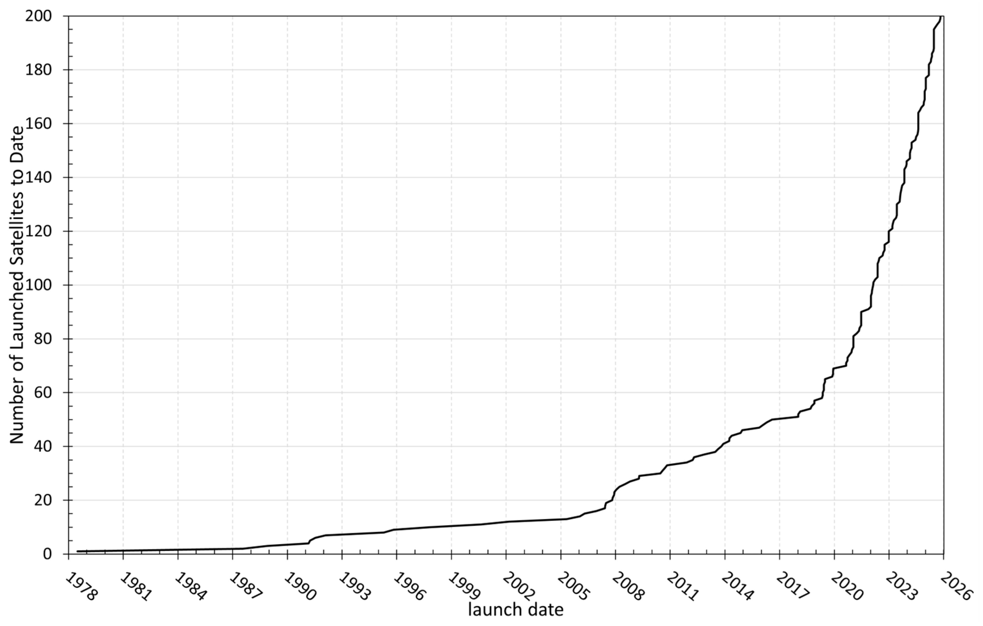
Figure 1. Total number of launched satellites with SAR payloads as a function of time.
Remotesensing 17 03773 g001
Figure 2. Satellite mass versus launch date from 1978 to 2025. Satellites with unknown mass are plotted at a reference level of −1000 kg.
Remotesensing 17 03773 g002
Figure 3. Satellite mass versus launch date from 2006 to 2025 for mass less than 3 tonnes. Satellites with unknown mass are omitted as well as ALOS-4, LuTan and Topaz satellites which exceed the 3-tonne threshold.
Remotesensing 17 03773 g003
Figure 4. Satellite average mass as a function of time.
Remotesensing 17 03773 g004
Figure 5. Radar swath width in time for Spotlight (blue), Stripmap (red) and ScanSAR (green) modes. Microsatellite constellations are reported in black.
Remotesensing 17 03773 g005
Figure 6. Azimuth (+) and range (x) resolutions in time for Spotlight (blue), Stripmap (red) and ScanSAR (green) modes. Microsatellite constellations are reported in black.
Remotesensing 17 03773 g006
Figure 7. Area of resolution cell in Spotlight mode as a function of launch date for each satellite (black circle) and its mean value in time (black line).
Remotesensing 17 03773 g007
Figure 8. Ratio between swath width and resolution cell area in ScanSAR mode as a function of launch date for each satellite (black circle) and its mean value in time (black line).
Remotesensing 17 03773 g008
Table 1. Characteristics of SARs launched by USA [9,10,11,17,18,19] (most data retrieved from [11]).
ParameterSeasatSIR-ASIR-BSIR-C
BandLLLL/C
Wavelength (cm)23.523.523.423.9 (L)/5.7 (C)
Antenna (L × W, meters)10.7 × 2.169.4 × 2.1610.7 × 2.1612 × 2.95 (L)/0.7 (C)
Bandwidth (MHz)1961210, 20, 40
PolarizationHHHHHHHH, HC, VH, VV
Transmitted peak power (kW)111.24.4 (L)/1.2 (C)
PRF (pps)1464–16471464–1824not available1395–1736
Elevation angle (°)20.54715–6020–55
Swath width (km)1005010–6015–60
Ground-range resolution (m)254017–5810–60
Azimuth resolution (m)25402525
Table 2. ASAR working modes.
ModePolarizationIncidence (°)Resolution (m)Swath (km)
Alternating PolarizationHH/VV or HH/HV or VV/VH15–4530–15058–110
ImageHH or VV15–4530–15058–110
WaveHH or VVnot available95 × 5 (every 100 km)
Suivi global (ScanSAR)HH or VVnot available1000405
Wide swath (ScanSAR)HH or VVnot available150405
Table 3. RADARSAT mission comparison (adapted from [88]).
ParameterRADARSAT-1RADARSAT-2RCM
Launch4 November 199514 December 200712 June 2019
Altitude793–821 km793–821 km586–615 km
Inclination98.6°98.6°97.7°
Repeat cycle343/24343/24179/12
LTAN18:0018:0018:00
Launch mass2750 kg2200 kg1400 kg
Nominal lifetime5 years7 years7 years
Complete coverage2–3 days2–3 daysdaily
Bus dimensions3.55 m × 2.46 m3.7 m × 1.36 m3.6 m × 1.1 m
SAR antenna mass679 kg750 kg400 kg
SAR antenna dimensions15 m × 1.5 m15 m × 1.5 m6.75 m × 1.38 m
PolarizationHHquadquad
Bandwidth30 MHz100 MHz100 MHz
Finest resolutions8 m × 8 m (Stripmap)1 m × 3 m (spotlight)1 m × 3 m (spotlight)
Disclaimer/Publisher’s Note: The statements, opinions and data contained in all publications are solely those of the individual author(s) and contributor(s) and not of MDPI and/or the editor(s). MDPI and/or the editor(s) disclaim responsibility for any injury to people or property resulting from any ideas, methods, instructions or products referred to in the content.