1. Introduction
Since the earliest space missions, pioneers in space research have identified the ability to accurately determine and control the relative motion of two Spacecraft (SCs) as a critical factor. This problem was tackled in the Gemini 6 and 7 missions, launched in 1965, to carry out the first space rendez-vous manoeuvre between two manned spacecraft [
1]. From then on, the scientific community has been studying the potential of Satellite Formation Flying (SFF) in space missions.
SFF allows addressing some of the most interesting challenges in scientific research conducted from space, placing this technology at the forefront of space mission development and providing significant advantages over missions employing large monolithic satellites [
2]. The key feature of a formation is the distribution of both sensor and computational units across different satellites, enabling them to work in unison towards a common scientific or technological objective. This distribution offers important advantages such as flexibility and adaptability, redundancy and fault tolerance, as well as reduced development time and costs. Simultaneously, the multitude of possibilities offered by SFF exponentially increases engineering challenges [
3,
4], requiring the use of advanced techniques for estimation and observability of the positioning of each satellite [
5]. The first hurdle in SFF is the determination of the formation state, which involves the precise and constant estimation of the relative positions and velocities of the elements constituting the SFF. The precision required in such missions is typically addressed using expensive, ad hoc-designed measurement systems, as seen in missions like SWARM, PRISMA, and PROBA-3. In [
6], a four-year analysis of SWARM mission data is conducted to calibrate orbital determination algorithms, resulting in the in-flight estimation of antenna phase centre offset and variation. In [
7], the in-flight results of the PRISMA mission are analysed. PRISMA is specifically designed to qualify autonomous flight units and algorithms for formation flying and rendez-vous, achieving very high levels of precision on the order of centimetres.
In high orbits, where GNSS signals are weak due to multipath effects, low signal-to-noise ratios, and occasionally poor satellite geometry, the Dilution of Precision (DOP) increases, and the spacecraft formation flying (SFF) determination problem is addressed using active sensors. As demonstrated in [
8], relative range measurements obtained from inter-satellite transceivers can significantly enhance the accuracy and robustness of formation determination. The DOP values (e.g., HDOP, VDOP, GDOP) are commonly used in GNSS to provide a measure of how the satellite geometry affects the expected positioning accuracy. They give a good first indication of the quality of the satellites’ configuration, assuming ideal measurements. However, DOP values do not capture the sensitivity of the SFF mathematical problem. Instead, the condition number, which will be used in this article, is a metric that can be applied to any system of equations, including the methods presented in this article for determining the SFF.
For missions in low-Earth orbit, on the other hand, it is possible to use passive measurement systems based on GNSS signals. Rad-hard GNSS receivers, qualified for space, can significantly increase mission costs. While this is not a problem for most ambitious missions, it renders the adoption of such receivers unfeasible for the numerous low-cost missions being considered today. The challenge posed by the democratisation of space and the many innovative mission proposals based on SFF requires working with limited budgets, often leading to the integration of Commercial Off-the-Shelf (COTS) hardware not qualified for space use. In this research, this problem has been addressed by tackling the SFF determination using low-cost GNSS receivers. The first objective was to evaluate the performance achievable by COTS hardware under space conditions. A framework based on Software-Defined Radio (SDR), developed in a previous study [
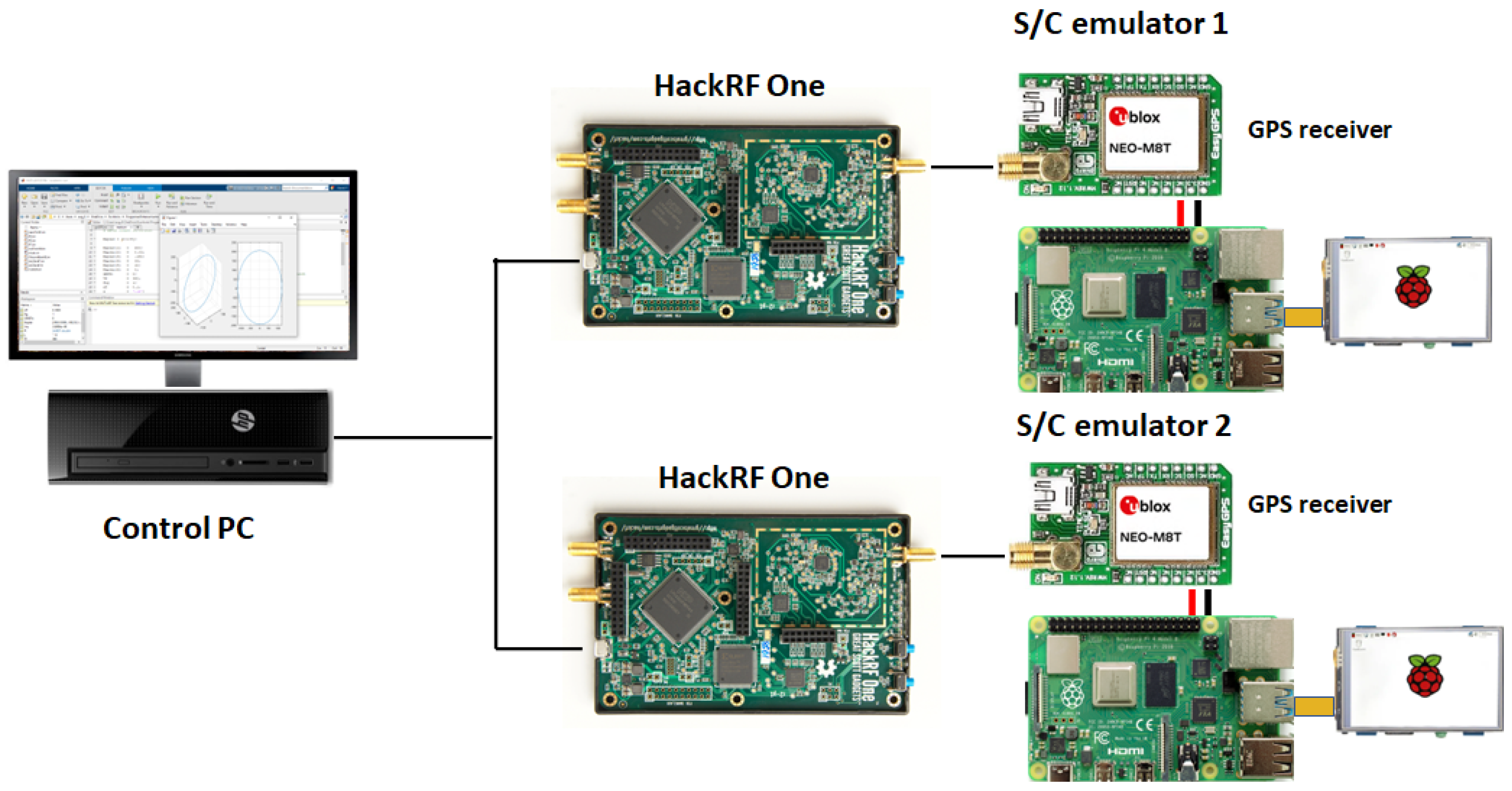
9], allows for emulating the orbital environment by generating the GNSS signals that a receiver would receive at each point in the orbit.
Figure 1 shows the hardware configuration of the framework.
Using this SDR-based environment, it is evident that the main source of error under these conditions is not atmospheric disturbances but instrumental error, primarily due to characterised hardware latencies and high velocity of the orbiting spacecraft. Therefore, when determining the formation state, the sensitivity of the methods used to perform these measurement errors must be evaluated. The sensitivity of the methods is evaluated by the condition number for matrix inversion of the system of equations that needs to be solved in the trilateration problem. The analysis reveals that some classical methods, such as Differences and Double Differences, suffer from conditioning issues. The conditioning evaluation provides a useful tool for designing new GNSS systems on Earth and on other planets or natural satellites. It complements other types of analyses, such as those presented in [
10], where a methodology for optimising a lunar navigation satellite constellation is proposed, taking into account objectives such as surface coverage. In [
11], observables from the Global Positioning System (GPS) and Beidou Navigation Satellite System (BDS) constellations are combined to achieve more precise orbital determination.
The data were processed using the Bernese GNSS Software 5.2, a high-precision scientific package developed by the University of Bern for precise orbit and geodetic parameter estimation [
12]. The integration of GPS and BDS observations notably enhanced the orbit determination accuracy of the TH02-02 satellites.
In this type of constellation fusion, it would also be highly interesting to analyse the system conditioning as performed in our work. Furthermore, the environment used in this research could also emulate multiple constellations. On the other hand, the use of commercial receivers under space conditions presents several challenges in the design of a low-cost space mission, as measurement errors and instrumental delays need to be efficiently identified and corrected. This problem is not commonly addressed in the scientific literature, as most consulted works assume optimal conditions in their measurement devices. In [
13], the antenna phase centres are taken into account for precise orbit determination using the method of Double Differences (DD) and ambiguity resolution. In [
14], the accuracy of formation determination is analysed using the DD method with GNSS observables, assuming high precision. In [
15], a different estimation technique is implemented, utilising other sensors to improve relative navigation accuracy and implementing specific feedback for relative formation control separate from absolute control. In [
16], differentiated GNSS signals are processed separately rather than in combination, using common GNSS satellites solely for the resolution of integer ambiguities in double-difference DD observations, thereby eliminating the need for bias estimation. The analysis considered for determining clock errors in this study follows the methods implemented in [
17]. This work implements an iterative least-squares process to optimize GPS observation data using an orbital model of the GPS satellites. Clock errors are considered to enhance the precision of orbital parameter estimation; however, the conditioning of the system to be solved is not addressed.
An important contribution of this work has been the addition of Hardware in the Loop (HIL) to introduce instrumental errors with maximum realism. In [
18], artificial intelligence and predictive filters are used for spacecraft position estimation using a vision system. Comparisons are made between the synthetic domain and one with HIL, resulting in errors in the order of centimetres. In [
19], the in-orbit verification of antenna phase centre calibrations based on neural networks for a microwave range measurement system is presented. It would be interesting to evaluate the reliability of such techniques against the measurement errors highlighted in our work. Artificial intelligence is expanding into all areas, including space. There is significant reluctance to apply these techniques in space due to their lack of reliability and resource-intensive nature. An environment like the one presented in this paper can allow for the evaluation of the robustness of such techniques against instrumental errors. In [
20], a testbed, called the Virginia Tech Formation Flying Testbed, is used, which integrates the general ionosphere electrodynamics model to simulate equatorial plasma bubbles and study the impacts on GNSS signals tracked by Low-Earth Orbit LEO satellites. Such ionospheric effects could also be integrated into the framework developed in our project. An important aspect in the final implementation is the characterisation of sensors. In [
21], the objective was to fully characterise the proposed sensor architecture for the HERMES mission, highlighting the available performance for attitude and orbit determination. All results were derived from an HIL environment, providing a rigorous description of the sensing capabilities to ensure performance. The research allows to characterise of low-cost GPS sensor environments, revealing significant limitations in processing, measurement, and documentation that had to be overcome through mathematical handling. The publication [
22] proposes a solution for close formation flying of unmanned aerial vehicles using cooperation and relative estimation techniques to achieve extreme accuracy in the position and orientation of the aircraft, thus reducing costs and improving efficiency in aviation. This concept can be extrapolated to a space scenario of SFF, where the SFF is represented as a graph, assuming that the SC correspond to the nodes and their connections represent the relative measurements between the SCs. This experiment can be implemented in the emulator system used in this work since each emulator unit of the SC has the ability to exchange information with the other units. Most of the research discussed above emulates environments that assume the ideal behaviour of the sensors used. In low-cost missions, the GNSS receivers used do not behave ideally. This article shows that a low-cost commercial GPS, working in orbital conditions, introduces quite significant measurement errors. It is therefore necessary to quantify the sensitivity of the algorithm to these errors. This sensitivity analysis can be applied to several of the above-mentioned investigations and to the design of new GNSS constellations, whether for the Earth, the Moon, or Mars.
The framework used to emulate a GNSS constellation and quantify the measurement errors introduced by a COTS GPS is described below. In the Formation Flying Determination section, the trilateration problem is modelled as a non-linear system of equations. The most common approach to address non-linear systems uses linearization around proxi values, which means working with an approximate model. In contrast, in this section, an exact model is proposed, with a linear system of equations subject to a non-linear constraint. This approach has its drawbacks, which will be affronted in the article. The condition number is introduced as a measure of the sensitivity of the algorithm. Models for SFF determination are also generated using the approach of differences and double differences. Finally, in the Experimental Validation section, the behaviours of the presented models are validated using data recorded by a low-cost GPS receiver. In the conclusions, the results obtained with the different methods are compared. In summary, this work bridges the gap between theoretical formation determination methods and their practical implementation using affordable commercial hardware. By integrating Hardware-in-the-Loop emulation of GNSS-based positioning models, it provides a realistic and controlled framework to analyse how measurement errors and system conditioning affect formation determination accuracy. The study not only evaluates the performance limits of COTS receivers under orbital dynamics but also proposes a methodological approach for assessing algorithmic sensitivity through conditioning analysis. These contributions aim to support the design of future low-cost formation flying missions and GNSS systems for Earth and planetary applications.
2. Framework Description
The HIL test bench used in this research is an evolution of the framework described in [
9]. It is divided into two blocks: the simulation environment and the scenario under test.
Figure 2 represents the conceptual design of the HIL test bench, where spread-spectrum signals, Similarly to those transmitted by the GNSS constellation, are emulated by an SDR transmitter at a power of +10 dBm. The transmitted observables are pseudorange and carrier phase on L1, and simulation times are programmable by the user. When setting up the tests, the input parameters to the system consist of a navigation RINEX (Receiver Independent Exchange Format) file and the SCs (spacecraft) orbits as a Two-Line Element (TLE) file, which describes satellite orbital positions. The reception is performed using a commercial-off-the-shelf (COTS) GPS receiver [
23].
The data is stored in a Comma-Separated Values (CSVs) file, and the analysis is done in Python 3.14.0. A system of this kind is composed of a GNSS (Global Navigation Satellite System) generator and receiver with an onboard computer that processes measurements (pseudorange, carrier phase, and emission ephemeris satellite orbital data) while applying real-time estimation and control algorithms. This setup allows for highly complex scenarios at the discretion of the user.
In the validation stage, low-cost GPS receivers are being used to determine the orbital position of the SCs (spacecraft). These receivers do not provide orbital position in space orbits due to the Wassenaar agreement (an international arms control arrangement [
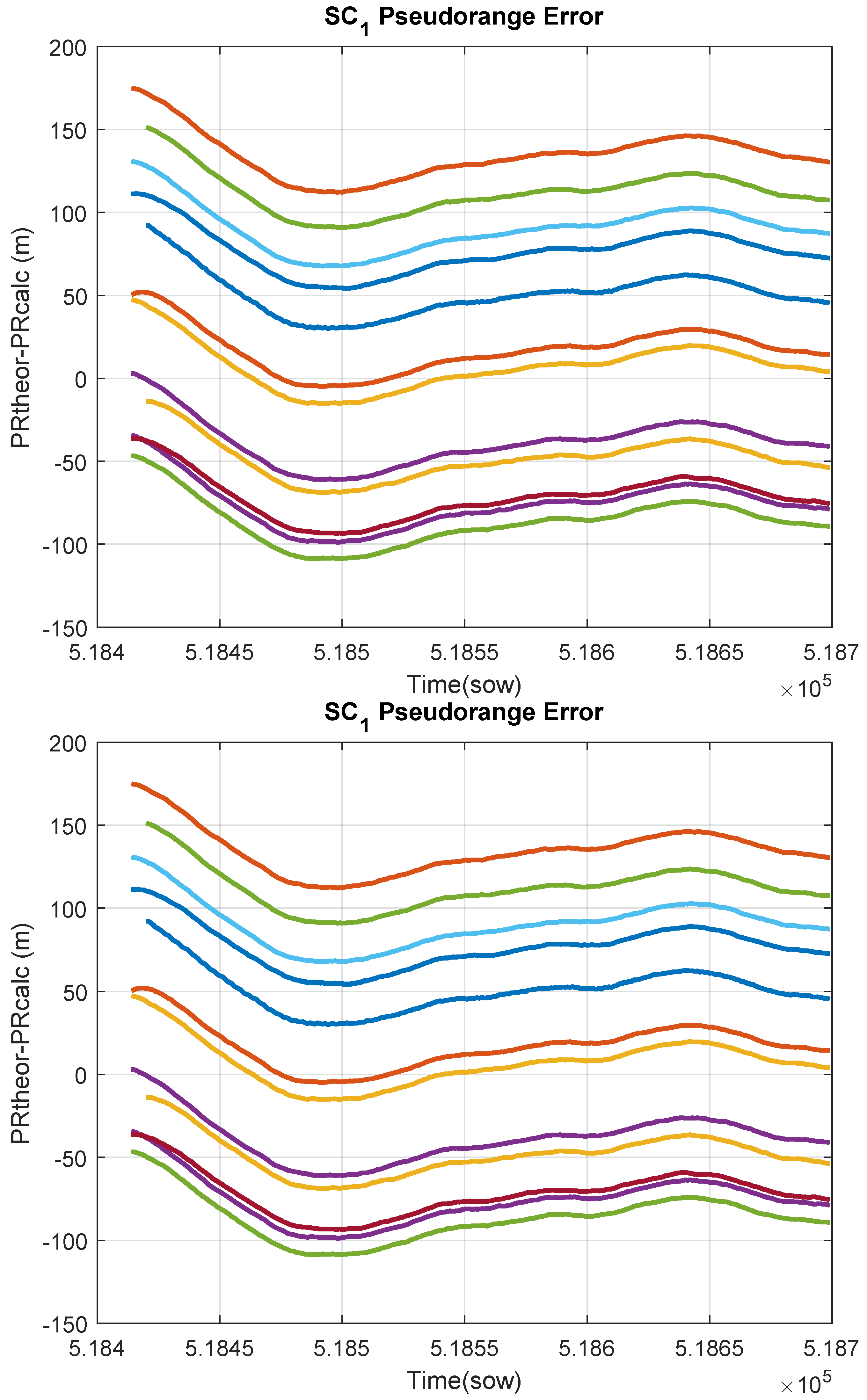
24]), but they do provide the measured pseudorange data (the calculated distance between satellites and receiver). By applying relativistic corrections (adjustments for effects due to relativity) and compensating for instrumental errors of the emitters, estimated pseudoranges are obtained, which closely resemble the theoretical values. As shown in
Figure 3, the pseudorange estimation exhibits an error on the order of 100 m. These errors are acceptable for a low-cost GPS, as they correspond to a time error of 300 ns (nanoseconds), which represents a demanding temporal resolution for digital instrumentation.
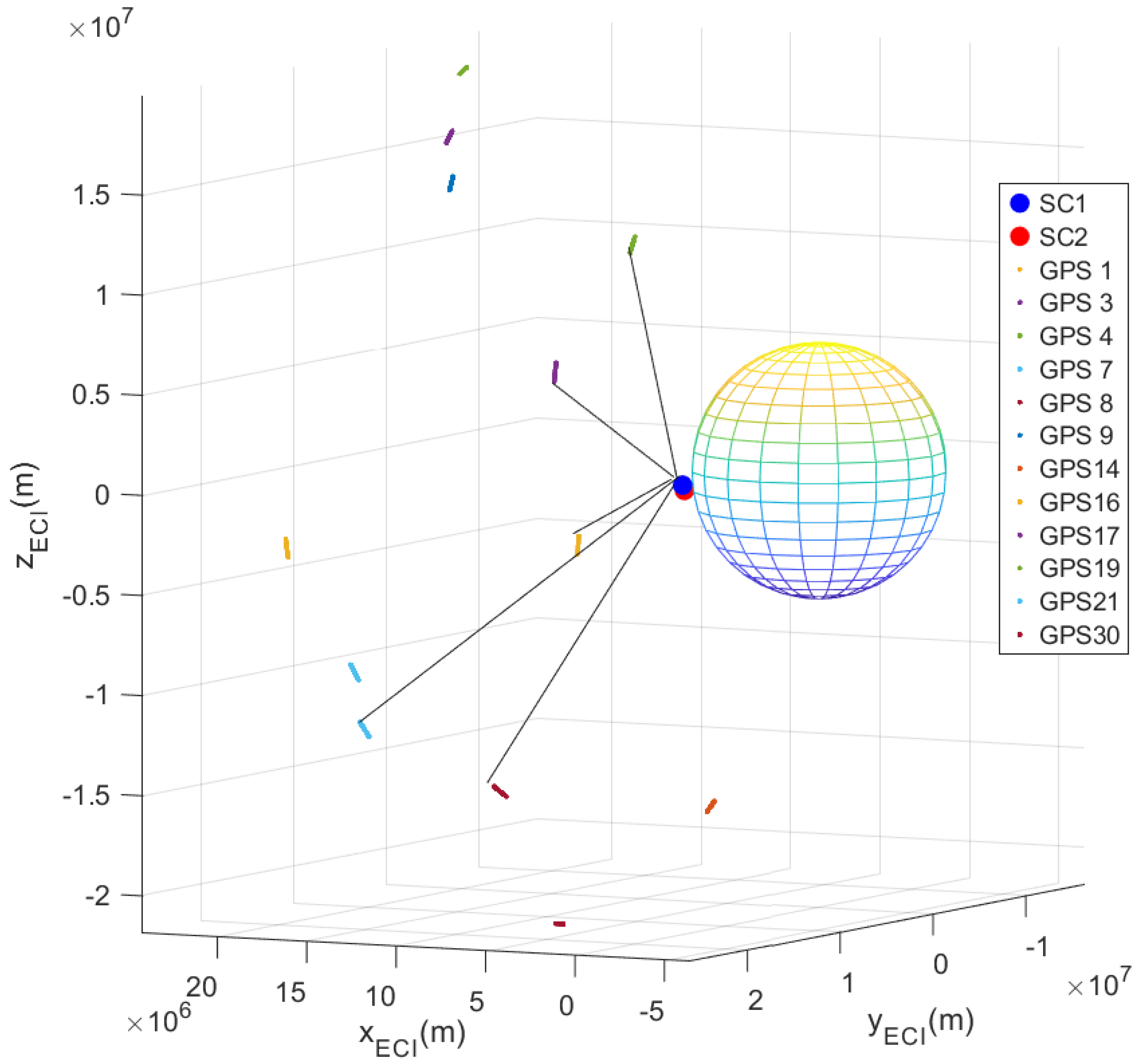
To estimate the orbital position of the SCs, a trilateration algorithm must be applied, which uses as inputs the estimated pseudoranges and the positions of the transmitters of the GPS constellation, as it is shown in
Figure 4.
3. Formation Flying Determination
The formation state can be determined using two approaches: either by determining the state of each SC separately or by directly determining the state of the entire group of SCs. First, an analysis of the trilateration problem formulation will be presented. Subsequently, trilateration solutions will be proposed for each of the proposed approaches. Finally, a method will be proposed to analyse the sensitivity of the obtained solutions to measurement errors.
3.1. Trilateration Problem
The trilateration problem consists of determining the 3D position , , of an SC, , based on the distances to several GNSS transmitters, , known as pseudoranges , and the positions of these GNSS transmitters . Additionally, the local pseudorange error, , is often estimated. The main component of this error is attributed to the receiver clock error, , which introduces an extra range distance, , where c is the speed of light. In this article, the local pseudorange error will be estimated instead of the local clock error because in a low-cost GPS receiver there are other sources of error that contribute significantly to the pseudorange measurement. Furthermore, we will later work with the system condition number, and to obtain an acceptable physical interpretation of it, we need all variables to be of the same order of magnitude, which is achieved by working with distances instead of times.
3.2. SCs Trilateration System
From the distances between GNSS constellation transmitters and the receivers of the SCs, an equation can be generated for each pair
. For each
, a system of nonlinear Equation (
1) can be constructed, with as many equations as received by GNSS satellites
from the constellation.
where the
values are the measured pseudoranges. The unknown to be calculated is the state of
, which consists of: the spatial coordinates
,
, and
, and the local pseudorange error,
.
Following the approach proposed in [
25] a new dependent variable
is introduced to transform the nonlinear system of pseudorange equations into a linear form, as shown in Equation (
2). This reformulation allows the original quadratic equations to be expressed as a matrix system
, which is linear in the unknowns
. The inclusion of the variable
enables an exact linearization that eliminates the need for iterative methods, reduces computational complexity, and avoids convergence issues, while allowing an additional constraint to be imposed to ensure the uniqueness of the solution.
3.3. Solution of Trilateration System
In the previous model, both the matrix and the vector are exclusively constructed from the positions of the transmitters and the pseudoranges estimated from the receivers’ measurements. The solution vector contains the variables to be determined. In fact, the first variable, r, is linked to the rest through a quadratic constraint. This constraint must be soft, allowing for unmodeled measurement errors to be accommodated. Depending on the number of available transmitters (rows) and the number of variables to be determined (columns), the linear system can be underdetermined, determined, or overdetermined.
With 4 independent transmitters, it is an underdetermined system with multiple possible solutions. In this case, the general solution will be a linear combination of a particular solution,
, and the homogeneous solution,
(
3).
To calculate the value of the parameter t, the system constraint can be applied to the general solution, resulting in a second-degree equation with two possible solutions. One solution corresponds to an orbital altitude higher than the GNSS constellation, and the other solution corresponds to a lower altitude. You only need to select the solution that matches the SC orbit.
With 5 independent transmitters, a determined system is obtained, and its solution is trivial.
With 6 or more independent transmitters, an overdetermined system is obtained, and a solution can be found using least squares or by the pseudoinverse matrix.
3.4. Condition Number of the System of Equations
Given a non-singular matrix
, the condition number for inversion, denoted as
, is defined as (
4).
where
represents a matrix norm, and
is the inverse of matrix
A. The condition number of the matrix of a linear system of equations indicates how sensitive the system’s solution is to small changes in the system. In [
26], it is demonstrated that the condition number of the system matrix can be used to calculate an upper bound on the relative error of the solution, as shown in Equation (
5).
In the formulated trilateration problem, the input to the system is the vector
, which is calculated from the measured pseudoranges and the positions of the transmitters. If the condition number of the system matrix is high, the system is ill-conditioned. In this situation, the equations are nearly dependent and thus, measurement errors can be amplified, introducing significant errors in the system’s solution. On the other hand, if the condition number is close to 1, the system is well-conditioned. This means that the equations are highly independent, and the errors in the system’s solution will be of the same order as the measurement errors. Therefore, the condition number indicates how measurement errors are translated to the trilateration solution. When redundancy is available, the condition number can be used to select the GNSS transmitters that generate a better-conditioned system. The combination of equations, i.e., transmitters
, that produces a lower condition number will result in a system with a solution that is less sensitive to measurement errors or to disturbances. Additionally, this propagation of errors can be very useful for tuning filters that rely on these results, such as Kalman filters [
27]. This stage is not included in this article to avoid obscuring the sensitivity of the final solution to the measurement errors. As will be seen in the validation section, for the presented trilateration problem, systems with 4 GPSs can be found to be well-conditioned, but the same does not happen when using 5 or more GPSs. In the 5-equation system, the variable
r has much higher values than the rest, as it is essentially the square of the orbital radius of the GNSS constellation. It is possible to reduce the condition number of the system matrix by scaling this component so that all matrix coefficients are of the same order. By dividing the
r component by the orbital radius of the GPS constellation, the condition number can be substantially reduced.
3.5. FF Trilateration by Differences
The relative position of two SCs,
and
, can be calculated by subtracting the equations of the same transmitter,
, resulting in Equation (
6).
By introducing the variables that define the state of the FF,
,
,
, and the variable
, which captures the nonlinear constraint, a linear system of 6 variables
can be created, as shown in (
7).
As will be seen in the validation stage, this system is ill-conditioned. Since it uses so many equations, it is not possible to find a configuration of 6 transmitters with a good condition number. Moreover, in this case, the underdetermined system cannot analytically be solved because the constraint is not a function of the system variables. One option to reduce the number of equations is to use a previous estimation of the state of each SC. Now, the variable
r can be calculated in advance, and the pseudoranges can be corrected with the local error of each SC. By applying this idea, a linear system of three equations and three unknowns is obtained, as shown in (
8).
As will be seen in the validation stage, the condition number of the reduced system will be better than the condition number of the full system, generating better results.
3.6. FF Trilateration by Double Differences
If the redundancy of transmitters is available, it is possible to eliminate the nonlinear term
r by calculating the difference of Equation (
6) for two different transmitters,
and
, resulting in Equation (
9).
By repeating this process for different transmitter pairs, it is possible to construct the system of linear Equation (
10), where the acronyms have been shortened (
,
, and
).
In this case, the non-linear constraint disappears, but at least 5 equations are needed. As each equation uses two emitters, at least 6 emitters common to both SCs are needed. As will be seen in the validation stage, this system will be ill-conditioned, due to the high number of equations and the lack of orthogonality of the 6 emitters. As in the previous case, the number of unknowns can be reduced by using the local pseudorange error obtained by trilaterating each SC separately, resulting in (
11). The variable vector is reduced to just three components,
. Now, only three equations are required, and thus, the two SCs must receive signals from at least 4 common transmitters. In this case, the system will be well-conditioned.
4. Experimental Validation
The described framework has been used to evaluate the sensitivity of the proposed methods to the measurement errors of the pseudoranges.
The process follows the following steps. The environment at each moment, propagates the orbits of the SCs and emulates the pseudorange signals measured by the GPS receivers of the SCs. The environment injects these signals into the antenna of the GPS receivers of the two SCs at the appropriate time. The on-board computers of the SCs read the pseudoranges measured by GPS receivers and apply the proposed algorithms. Finally, the determined positions of the SCs are compared against the propagated positions to validate the performance of the determination algorithms. The simulation period corresponds to 300 s, since we are limited by the memory of the SDR radio transmitting the GNSS signals.
In the determination stage, the first step is to preprocess the measurements. Based on the measured pseudoranges, the emission time is calculated, and the positions of the GPS transmitters are propagated for those times. The pseudoranges are also corrected. With the corrected pseudoranges and the positions of the GPS transmitters, the trilateration system of equations to be evaluated is built. The condition number is calculated for each of the possible combinations of GPS transmitters. Then, the system of equations is solved for the case with the lowest condition number. Finally, the determined positions are compared with the propagated positions to calculate the residuals and evaluate the goodness of the method.
4.1. SCs Trilateration
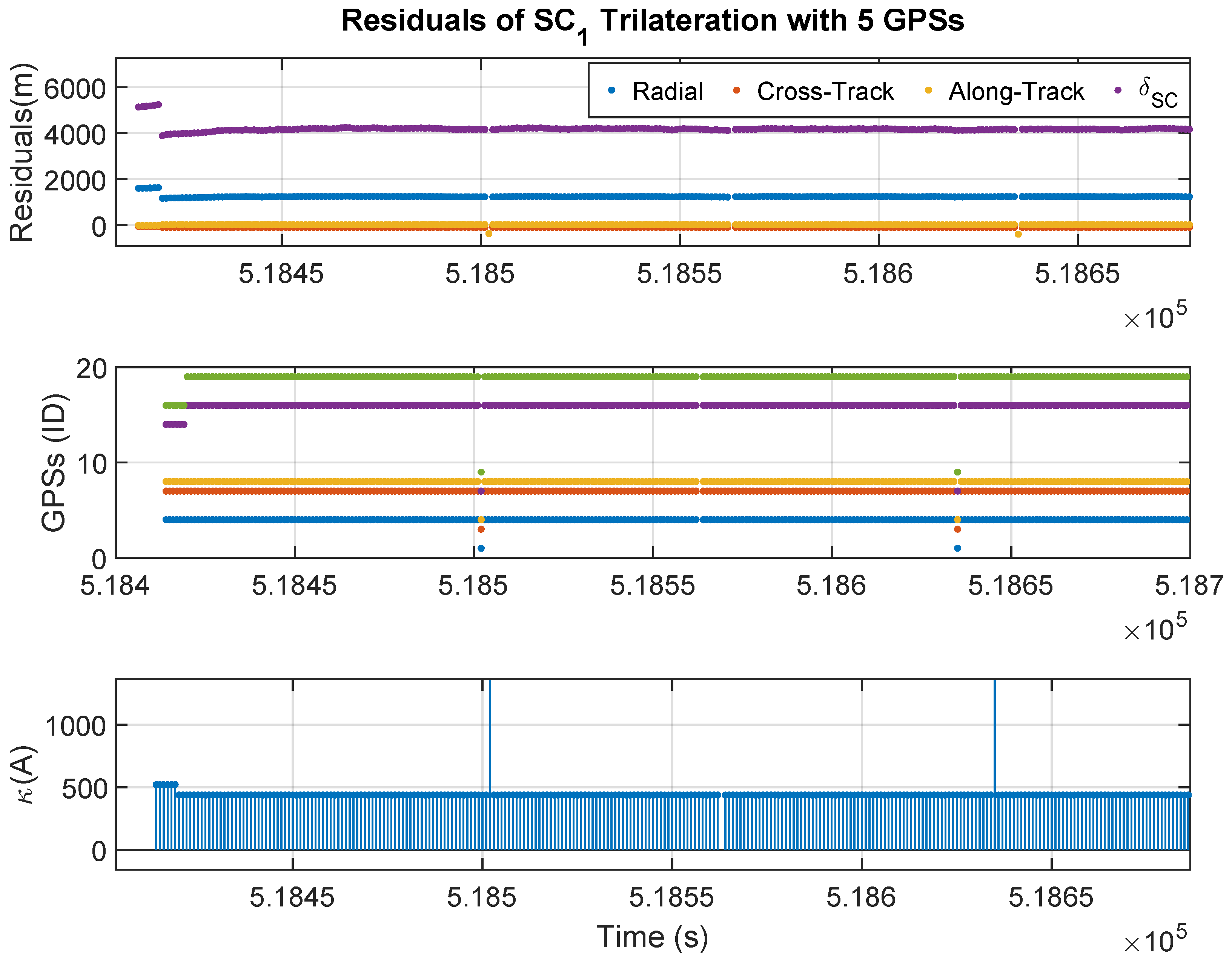
Using the signals of 5 GPS transmitters a determined system can be build, which solution is trivial.
Figure 5 shows the results obtained when determining the position of SC1 using 5 GPS transmitters.
In
Figure 5, the first graph shows the residuals of orbital positions (trilaterated minus propagated) in Radial, Along-Track, Across-Track axes and the local pseudorange error estimation,
. The second graph displays the identification numbers of the GPS transmitters used to construct the trilateration equation system. The third graph shows the condition number of the system matrix. It can be observed that the satellites used for trilateration change throughout the simulation, resulting in occasional losses of satellites. It can be observed that the residuals of the trilaterated position are extremely high, with errors of the order of kilometres. This is due to the high condition number of the system matrix, which is close to 500. As a result, the errors in the pseudorange measurements are amplified when the system is solved, leading to significant errors in the determined positions. These errors are also reflected in the estimate of the local pseudorange error.
In this case, it is possible to work with just 4 GPS satellites and find a solution to the underdetermined system using the constraint
. By using only 4 GPS satellites, a highly orthogonal configuration can be found, and the condition numbers is close to 5, two orders of magnitude lower than the previous case.
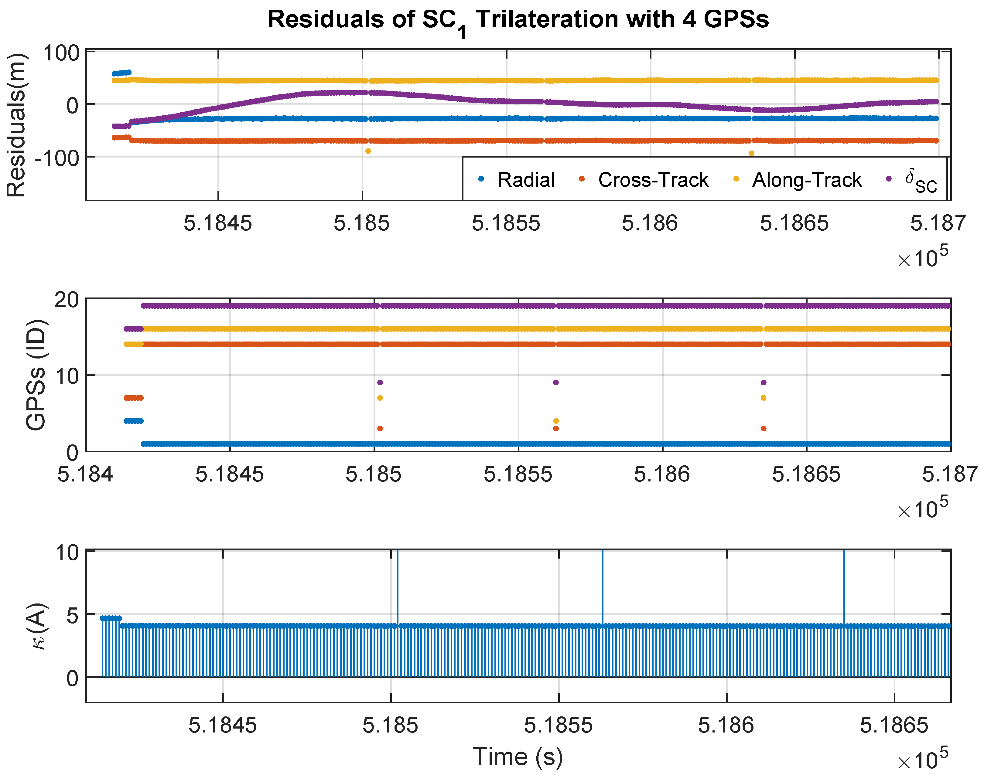
Figure 6 shows the results obtained when determining the position of SC1 using trilateration with 4 GPS satellites. Now, the system is well-conditioned, and the residuals of the trilaterated positions are of the same order as the pseudorange measurement errors. The GPSs used are quite orthogonal, except for some isolated moments when some GPS signal is lost. Now, the scale of the first plot allows to observe how the pseudorange error varies over time, which may be due to local clock drift.
Figure 7 shows the results obtained when determining the position of SC2 using trilateration with 4 GPS satellites. As the system is also well-conditioned, the residuals of the trilaterated positions are of the same order as the pseudorange measurement errors. On the other hand, the local pseudorange error behaves differently compared to SC1 because each GPS receiver has its own local clock error.
4.2. Determination of the Formation Flying by Trilateration of SCs
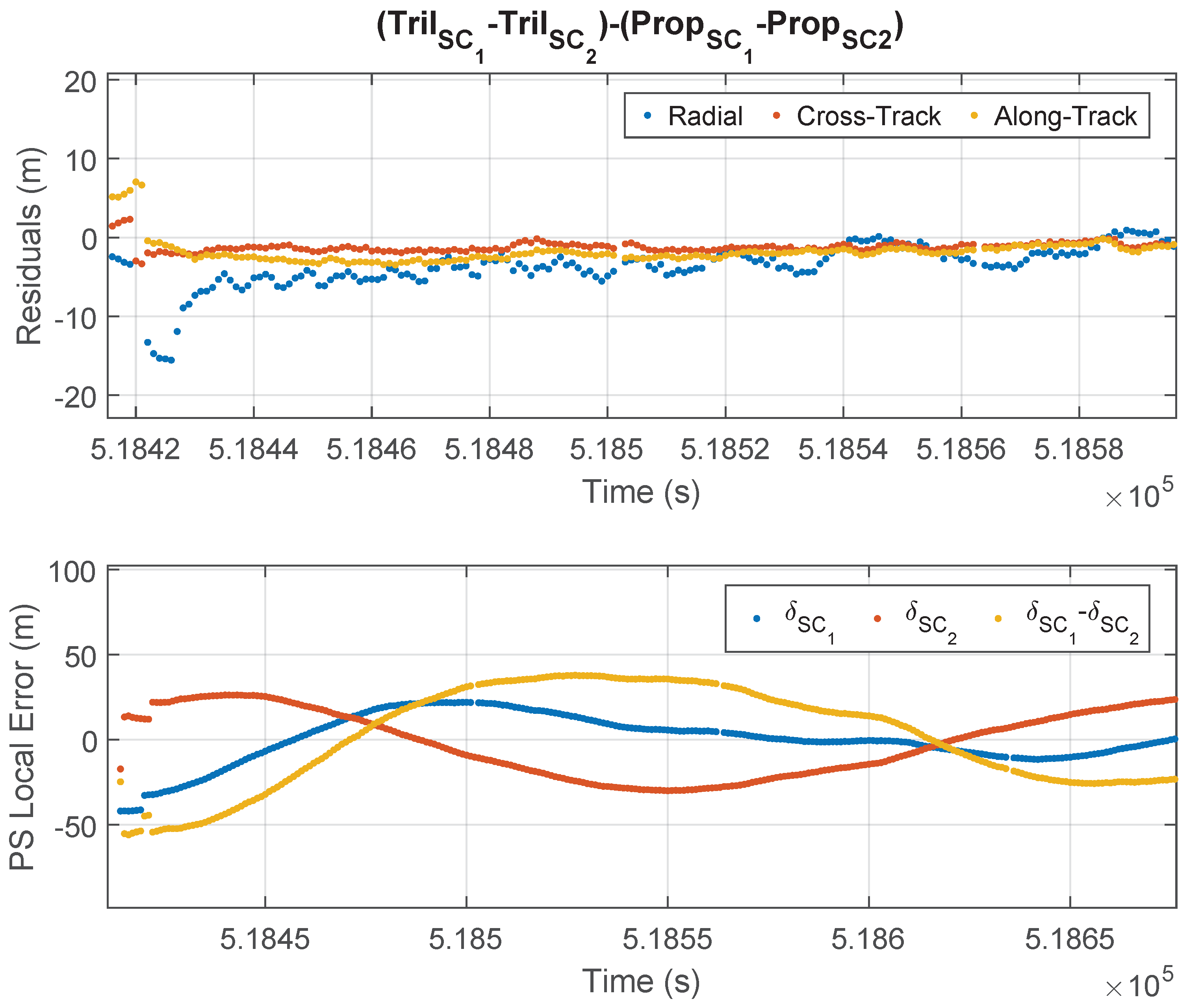
The simplest way to determine the relative state of the Formation Flying (FF) of two spacecraft (SCs) is to directly subtract the states determined for each SC separately. Despite the errors incurred during individual trilateration of each SC, when the determined positions are subtracted, the errors are significantly reduced. These results are shown in
Figure 8, where the first graph shows the error in estimating the relative position of the two spacecrafts and the second graph shows the estimate of the local pseudorange errors.
As the two SCs are in formation during the simulation, most of the time they use the same combination of GPSs, because they receive signals from the same GPS satellites and with similar geometry. Additionally, since they use the same model of GPS receiver, unmodeled instrumental errors are similar in both SCs, although not identical. On the other hand, in a real-world situation, the signal paths from the emitters to the receivers would also be similar for both SCs and therefore would experience similar perturbations.
In the second plot of
Figure 8, it can be observed that the estimates of pseudorange errors differ for each SC due to each local clock having its own drift. However, during most of the simulation, the error in the determination of the relative position is below 10 m. Only at the beginning of the simulation, when they use a different combination of GPSs, and when the receiver of SC1 loses some GPSs, larger errors occur. When they do not use the same combination of GPSs, some errors do not cancel out, resulting in errors Similarly to those of individual determinations.
4.3. FF Trilateration by Differences
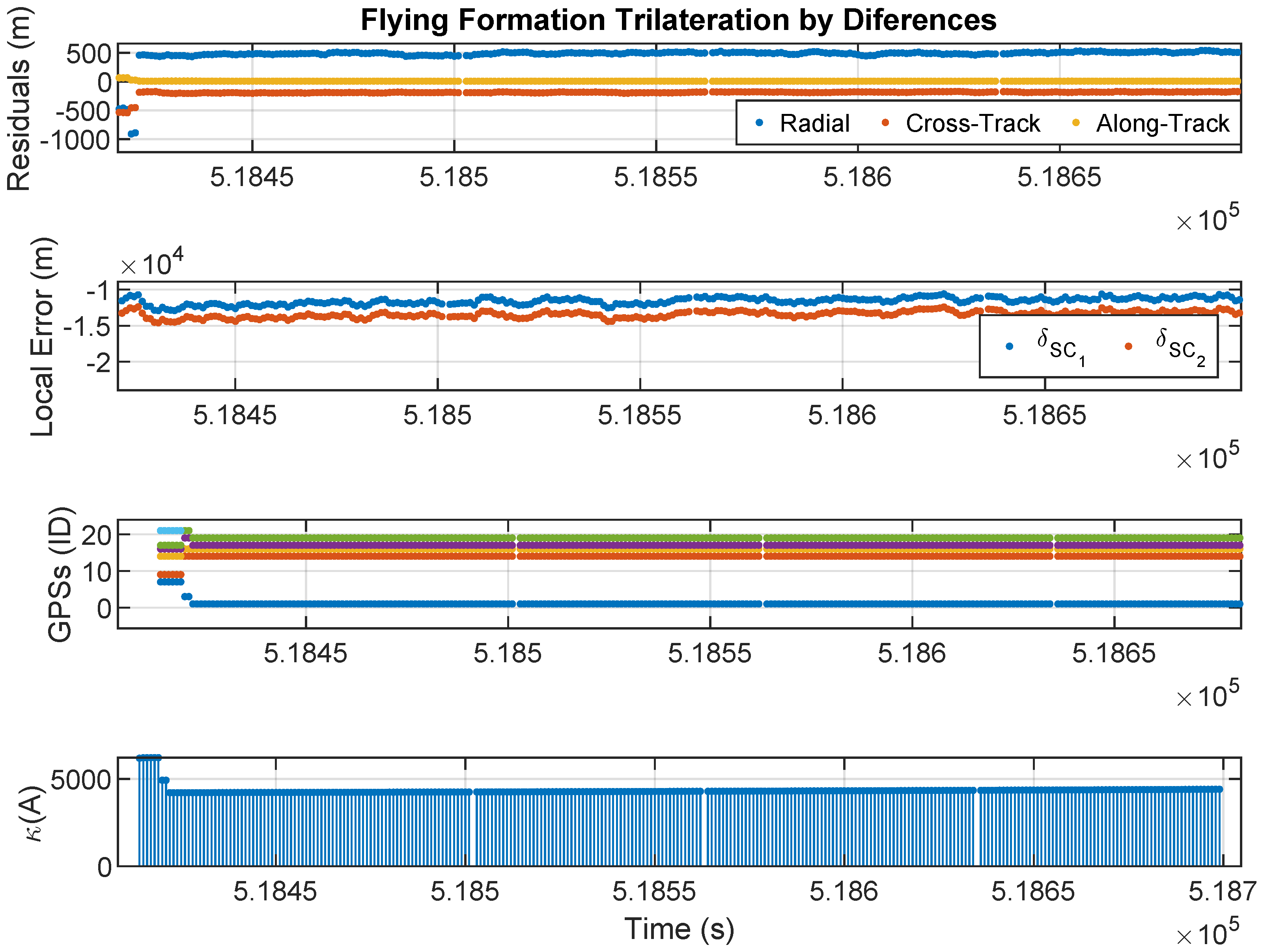
For this trilateration problem, it is not possible to find a solution in the undetermined case, as the constraint is not a function of the system variables. Therefore, it is necessary to solve the determined case, which requires the use of 6 GPS satellites. The results obtained are shown in
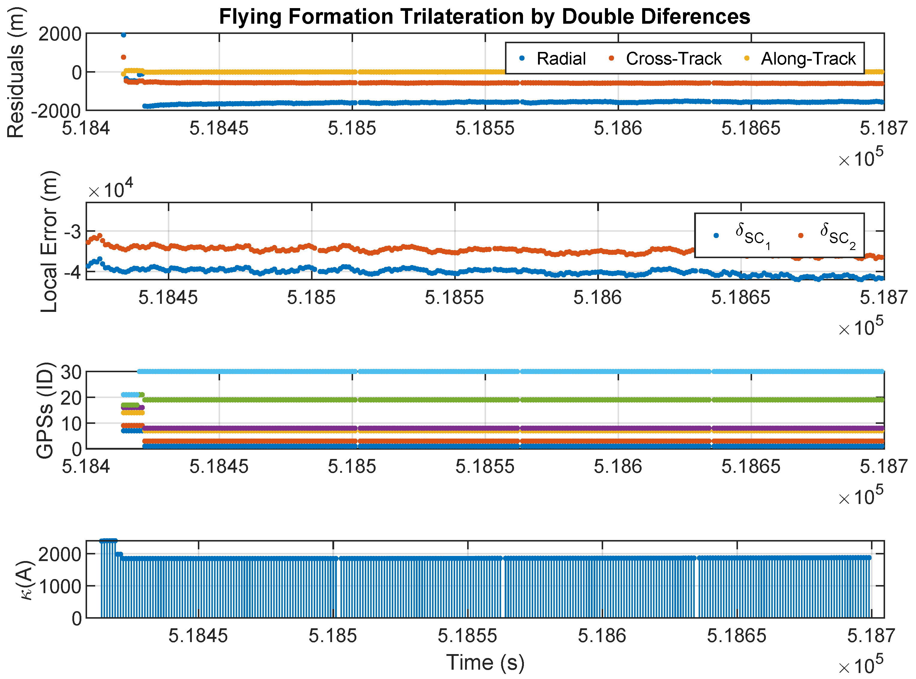
Figure 9, where the first graph shows the error in the relative position estimate, the second graph shows the local pseudorange errors, the third graph shows the id-number of GPSs transmitters used, and the forth graph shows the condition number of the system of equations.
This solution, despite cancelling terms in the equations, is numerically quite deficient, resulting in relative position errors of about 500 m. This is due to the use of 6 satellites, which leads to very high condition numbers, close to 5000. The estimates of the local pseudorange errors are even worse, in the order of .
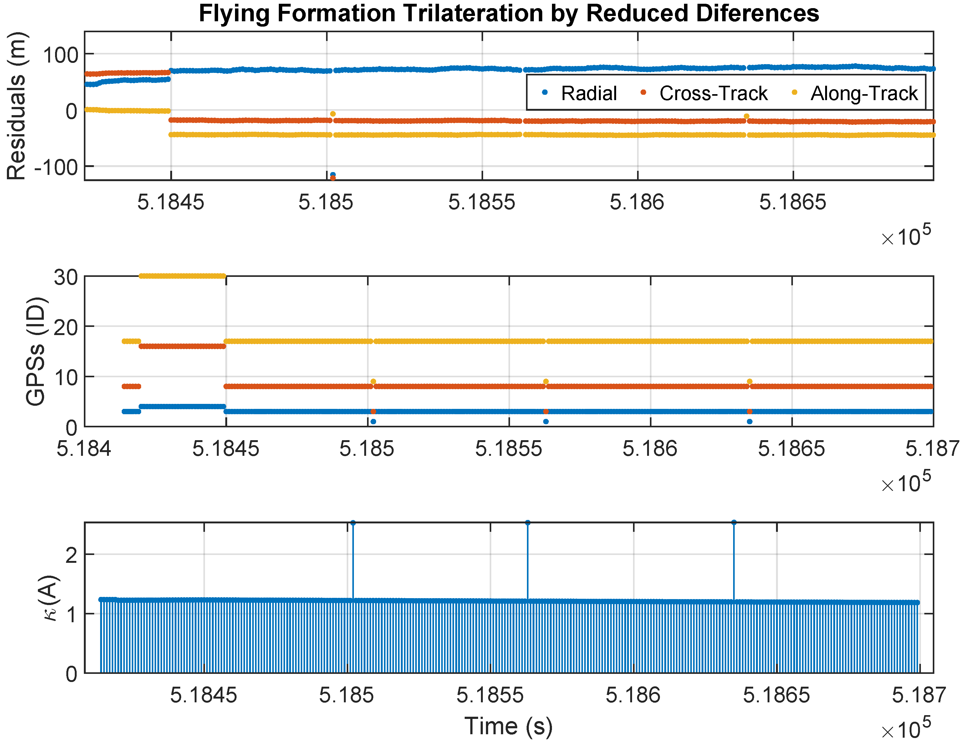
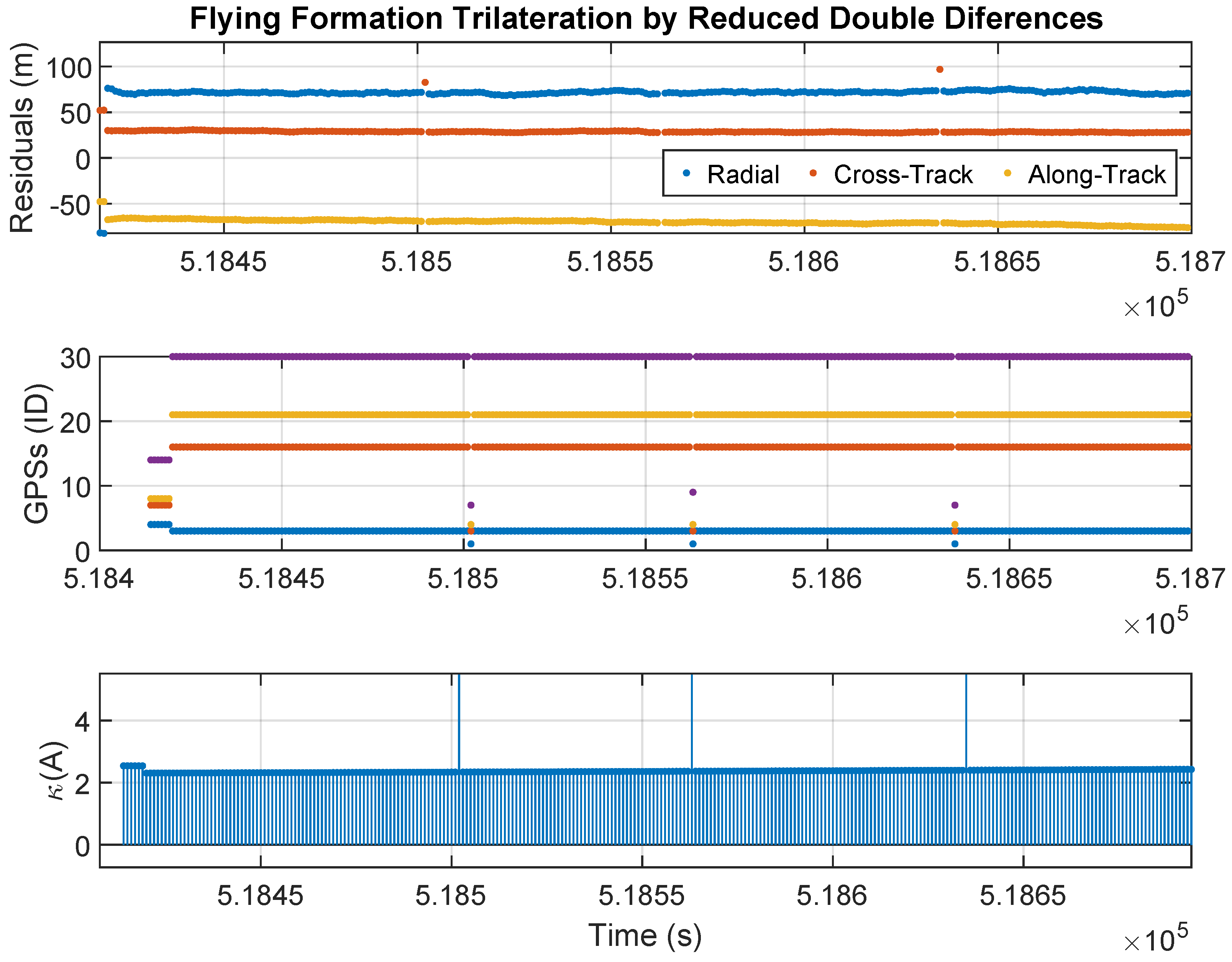
By using the individual estimation of the local pseudorange errors as data, the number of unknowns can be reduced to three, thus decreasing the number of equations and satellites required. This way, the problem becomes better conditioned, and better results are obtained, as shown in
Figure 10.
In this case, a very good condition number is obtained, of the order of 1. Therefore, the errors in the determination of the relative position are acceptable, of the same order as the errors in the individual determination of the SCs. Although the differences method should have cancelled out errors, this is not evident in the results because, in order to reduce the number of equations, estimated signals that included errors were used.
4.4. FF Trilateration by Double Differences
This method already eliminates the variable
r, and therefore it is necessary to solve a system of 5 equations and 5 unknowns. Each equation involves 2 GPSs, which means that at least 6 common GPSs are needed.
Figure 11 shows the results obtained.
The results obtained with this solution, despite cancelling multiple terms in the equations, are also quite poor. This is due to the high condition number of the system to be solved, as it involves 5 equations and 6 GPS satellites. The best possible combination of GPSs has a condition number close to 2000, which is lower than that obtained in the method of double differences because one equation is now removed. However, the errors in the estimation of the relative position are worse due to the additional GPS, which leads to a loss of orthogonality. The estimation of the local pseudorange errors is excessively high, of the order of .
This system can also be reduced to three equations, using the individual estimation of the pseudorange errors for each SC as input data. By reducing the system to three equations, better results are obtained, as shown in
Figure 12.
In this case, we obtain a well-conditioned system, but the condition number is slightly higher than the Reduced Differences method. Therefore, although the errors in the determination of the relative position are acceptable, they are slightly worse than in the Reduced Differences method. Despite cancelling more terms in the equations than the Reduced Differences method, the Double Differences method uses one more GPS satellite. Due to the lack of orthogonality in the GPS constellation, using more than 3 satellites increases the condition number of the system.
5. Conclusions
Hardware-in-the-Loop (HIL) simulation environments are valuable tools for analyzing formation-flying missions and obtaining results that closely represent in-orbit conditions. A GNSS-based simulation environment has been developed to assess the performance of commercial off-the-shelf (COTS) GNSS receivers in space scenarios. Using this environment, it is evident that COTS GNSS receivers introduce measurement errors in the pseudoranges. These errors are primarily attributed to high orbital velocities and the inherent precision limits of the measurement instruments. Other external disturbances encountered in space are comparatively less significant than those present in the atmosphere.
In the HIL experiments presented in this article, only the GPS constellation was used. However, the HIL environment is fully reconfigurable: by providing a multi-constellation RINEX file, it can incorporate observations from various GNSS systems (GPS, Galileo, GLONASS, BeiDou), creating hybrid satellite geometries. This capability would allow the system to trilaterate using several subsets of satellites that offer a more robust and accurate solution.
The solution to the trilateration problem based on GNSS has also been analysed. The problem is modelled as a system of linear equations with a quadratic constraint. Additionally, the use of the condition number is proposed to evaluate the quality of the method. Subsequently, this type of solution has been developed for the FF problem, applying the methods of differences and double differences. The algorithms presented here are deterministic; and the results they provide could feed into non-deterministic algorithms, such as Kalman filters, which would allow solving transients where there are not enough satellites available.
The proposed methods have been evaluated in the GNSS simulation environment, on a scenario with two satellites in a leader-follower formation, using two recently launched Starlink satellite TLEs. The GNSS Simulation environment highlights that under these orbital conditions, COTS GPS receivers used exhibit measurement errors in pseudorange of up to 100 m, which is expected due to the high orbital velocities. The results obtained from evaluating the different methods are summarised in
Table 1. This table quantitatively compares how the errors introduced by the commercial GPS receiver propagate through the different algorithms.
From these results, the following conclusions can be drawn:
Using as few satellites as possible is essential. Having more than 4 satellites makes it challenging to achieve favorable condition numbers, thereby introducing a significant level of mathematical error. However, this does not mean that the process cannot be repeated with other combinations of 4 satellites. Furthermore, the condition number for each combination could be used to calculate a weighted average of the different estimates.
The Difference method applied to the GPS constellation is ill-conditioned, as it involves too many equations/unknowns. It is possible to reduce the condition number by reducing the number of equations/unknowns, determining the SCs separately beforehand. In this situation, errors of the same order as the pseudorange measurement errors can be achieved.
The Double Difference method applied to the GPS constellation is also ill-conditioned and does not yield good results. It requires the use of 6 GPSs, and it is challenging for them to be sufficiently orthogonal. It is also possible to reduce the condition number by determining the SCs separately beforehand. With this reduction, a similar accuracy to the pseudorange measurement errors can be achieved.
The most accurate method for FF Determination is to determine the two SCs separately and simply subtract their determined positions. In this situation, very well-conditioned systems do not amplify the measurement errors. Additionally, since both SCs are in formation, they receive signals from the same GPSs and use the same combination. Finally, if both SCs use the same model of GPS receiver, they will commit similar errors in the measured pseudoranges. Under these conditions, most errors cancel out, leading to very high precision in position determination. However, in real-world missions, spacecraft may use different GNSS receiver models due to mission limitations or satellite replacement. In such cases, error cancellation might not occur, and the results could worsen. Nevertheless, the local pseudorange error of each receiver would be estimated as part of the unknowns in the system of equations, so most of the errors would not be transferred to the solution.
These results demonstrate that it is feasible to undertake satellite formation flight missions using COTS GPS receivers. To achieve this, it is essential to acknowledge the limitations of accuracy and assess the effectiveness of trilateration algorithms in dealing with measurement errors. Specifically, for the evaluated scenario, errors of the order of meters have been achieved, which is promising and opens the way for future applications of the methods presented here in the feasibility analysis of new formation flight missions.
The mathematical development in the article is valid for all types of orbits, although the numerical results may vary depending on the geometry. The advantage of using the condition number as a quality metric is that it allows us to select the best configuration in more adverse situations; for example, in orbits close to the orbital altitude of the GNSS constellation, it will allow us to avoid the most coplanar (less orthogonal) configurations.
