Abstract
Digital Beamforming SAR (DBF-SAR) provides high-resolution wide-swath imaging capability, yet it is affected by inter-channel amplitude, phase and time-delay errors induced by temperature variations and random error factors. Since all elevation channel data are weighted and summed by the DBF module in real time, conventional record-then-compensate approaches cannot meet real-time processing requirements. To resolve the problem, a real-time calibration architecture for Intermediate Frequency DBF (IFDBF) is presented in this paper. The Field-Programmable Gate Array (FPGA) implementation estimates amplitude errors through simple summation, time-delay errors via a simple counter, and phase errors via single-bin Discrete-Time Fourier Transform (DTFT). The time-delay and phase error information are converted into single-tone frequency components through Dechirp processing. The proposed method deliberately employs a reduced-length DTFT implementation to achieve enhanced delay estimation range adaptability. The method completes calibration within tens of PRIs (under 1 s). The proposed method is analyzed and validated through a spaceborne simulation and X-band 16-channel DBF-SAR experiments.
1. Introduction
With the development of spaceborne synthetic aperture radar (SAR) towards multi-mode, high-resolution wide-swath (HRWS), traditional single-channel SAR cannot simultaneously achieve wide swath and high image resolution due to the inherent limitations imposed by the minimum antenna area constraint [1,2,3]. Digital Beamforming (DBF) enhances the signal-to-noise ratio (SNR) and ambiguity performance of wide-swath SAR imagery without degrading resolution [4]. This is achieved through flexible beam steering with digital arrays [5] and joint space-time processing of multi-channel signals [6]. By improving system SNR and extending single-observation coverage, next-generation DBF-SAR systems offer substantial advantages for interferometric mapping techniques, including InSAR [7,8] and MTInSAR [9,10]. DBF has emerged as a critical research direction for next-generation spaceborne SAR systems due to its demonstrated advantages in HRWS imaging [11,12].
However, inter-channel inconsistencies in DBF systems can directly degrade signal coherence and reduce SNR [13,14,15]. The real-time beamforming process presents significant challenges for on-orbit channel error calibration [16]. Channel errors in DBF systems include amplitude errors, phase errors, and time-delay errors. Most conventional error estimation algorithms are based on echo signal processing, employing a record-then-compensate approach. Wu et al. proposed using isolated scatterers to extract unambiguous signals for channel mismatch correction [17]. Liu et al. achieved reference-free calibration by leveraging clutter spatial correlation [18]. Zhou et al. achieved joint high-precision estimation of Doppler centroid and phase errors through signal subspace uniqueness and antenna pattern weighting [19]. Cai et al. established an explicit model of virtual target amplitude-phase errors based on the minimum L1 norm in the image domain [20]. This approach eliminates the requirement for redundant channels while achieving high-precision channel error estimation. The above-mentioned methods demand significant computational resources. The latency between data acquisition and error estimation exceeds one second, failing to meet hard real-time requirements.
The Cal-Tone-based approach offers a feasible solution for real-time multi-channel error estimation [21,22,23]. However, it requires additional Radio Frequency (RF) components for cal-tone to support real-time calibration. Moreover, due to the periodic characteristics of single-tone signals, this method can only measure amplitude and phase errors, whereas time-delay errors cannot be estimated. Phase shifts exceeding due to time-delay errors cannot be distinguished from those caused by smaller delays in tone-signal-based methods, leading to measurement ambiguity. Existing time-delay error estimation methods primarily depend on external reference sources and encounter difficulties in attaining real-time processing capabilities [24].
Amplitude and phase errors primarily stem from temperature variations in the short term and component aging in the long term. Time-delay errors mainly originate from synchronization mismatches during initialization among multiple polyphase Analog-to-Digital Converters (ADCs) in multi-channel DBF systems. The sampling timing deviation introduces ns-level delays [25], typically manifesting as a full-sample or half-sample shift relative to the reference channel.
To ensure DBF-SAR’s inter-channel consistency, a real-time multi-channel error calibration architecture for calibrating amplitude, phase, and time-delay errors without requiring additional Radio Frequency (RF) components is proposed in this paper. The proposed method achieves a latency of only tens of Pulse Repetition Frequency (PRF) cycles (under 1 second). In synthetic aperture radar signal processing, the Dechirp algorithm serves as a critical bandwidth compression technique that downconverts wideband radar returns to narrowband signals, enabling efficient subsequent processing [26]. As a key innovation of our methodology, Dechirp-based preprocessing is applied to reduce the wideband Linear Frequency Modulation (LFM) calibration signal to a single-frequency component, enabling precise error calibration. This transformation enables high-accuracy error estimation through two distinct approaches. First, time-delay errors are translated into frequency offsets of the tonal signal. This linear conversion enables direct measurement through a basic Field-Programmable Gate Array (FPGA) counter, eliminating complex spectral processing. Second, the spectrally concentrated energy of the single-tone signal facilitates phase error detection through Discrete-Time Fourier Transform (DTFT) analysis. The proposed method achieves amplitude and degree phase accuracy under 20 dB SNR internal calibration conditions.
The internal calibration loop of the DBF-SAR system is illustrated in Figure 1. The direct digital synthesizer (DDS) produces an LFM waveform that undergoes in-phase/quadrature (I/Q) mixing to upconvert it to the RF carrier frequency. An RF switching matrix precedes the TR module, providing configurable signal routing to either the transmission path or TRM calibration loop. The signal coupled into the TRM calibration loop [27] is output through a circulator during the internal calibration procedure. The TRM’s output signal is amplified, mixed down, and filtered in the receiver chain to obtain the Intermediate Frequency (IF) signal.

Figure 1.
Block diagram of the top-level hardware structure of the DBF-SAR internal calibration loop. The received signals from each channel are amplified, downconverted (antialiasing filter follows), and digitized to the IF signals. The FPGA performs real-time multi-channel error calibration and DBF synthesis processing.
A weight generator and Intermediate Frequency Digital Beamforming (IFDBF) real-time processing architecture is proposed in [28]. In the IFDBF architecture, the ADC-sampled IF signal is converted to I/Q base-band via Digital DownConvertor. The IFDBF architecture supports multi-channel error compensation capabilities. Specifically, amplitude and phase errors are compensated through DBF weighting, while time-delay errors are corrected via digital delay components. In [28], errors are assumed as prior knowledge without addressing their acquisition methods. The proposed error estimation approach, which utilizes the IFDBF architecture for simultaneous estimation and compensation, can be effectively integrated with existing techniques to guarantee on-orbit operational reliability of DBF-SAR systems.
This paper is organized as follows. Section 2 introduces the proposed multi-channel error estimation and compensation algorithm. Section 3 presents the FPGA-based real-time processing architecture implementation. Section 4 verifies the performance and efficacy through simulations and experiments. Section 5 discusses the algorithm’s applicability to other multi-channel systems. Section 6 concludes the paper.
2. Proposed Methods
The proposed method employs a sequential three-stage architecture to address amplitude, time-delay, and phase errors, where each error type undergoes dedicated measurement followed by immediate compensation.
Considering a linear frequency modulation (LFM) signal. The calibration pulse transmitted by the internal calibrator can be expressed as
where and represent the pulse width and the carrier frequency, respectively; and and t denote the chirp rate and the fast time, respectively.
The calibration signal is transmitted through the internal calibration loop, passing sequentially through the TR module, microwave module, and calibrator before being received. A short delay occurs from signal transmission to reception. For a system exhibiting simultaneous amplitude error , phase error , and time-delay errors , the baseband signal received at the nth channel is expressed as follows:
The amplitude error can be estimated by performing a simple summation over the real part of the baseband signal .
The amplitude compensation value for the nth channel is:
After compensating for channel amplitude errors, all channels demonstrate consistent amplitude . This common scaling factor is algebraically eliminated in subsequent analyses. When recalibrating, the baseband signal received by the nth channel becomes:
The next step is time-delay error estimation. A critical challenge arises from the substantial frequency disparity between the space-grade FPGA primary clock (typically around 100 MHz) and the ADC’s sampling clock (typically exceeding 1 GHz). This frequency mismatch creates a fundamental limitation in accurately characterizing GHz-range clock timing errors using only a 100-MHz-range reference clock.
For precise time-delay estimation, the signal requires initial dechirping processing. Let denote the dechirping reference signal:
The dechirped signal received from the nth channel is:
The signal is essentially a single-tone waveform with a rectangular envelope and constant phase terms. The frequency of the single-tone waveform is:
Dechirp processing amplifies the inter-channel timing differences, making even minor discrepancies in the high-speed clock clearly observable in low-speed clock measurements. Section 4 validates the proposed algorithm’s effectiveness in compensating synchronization errors at sub-sample precision, specifically addressing half-sample-grid misalignments that may occur in polyphase ADC (time-interleaved ADC) clock architectures.
The single-tone signal is converted to a square wave, then the frequency is derived from period measurements instead of being measured directly. In FPGA implementations, square wave measurement can be efficiently realized through dedicated trigger circuits and digital counters.
Direct application of conventional single-threshold triggering would introduce glitches in the shaped square wave due to noise interference, as illustrated in Figure 2a. To mitigate this problem, a hysteresis comparator with Schmitt-trigger characteristics (with ±TH threshold window) was implemented. Although the shaped square wave demonstrates a consistent propagation delay compared to the source signal, this shift has no impact on cycle duration or frequency measurement, as demonstrated in Figure 2b.
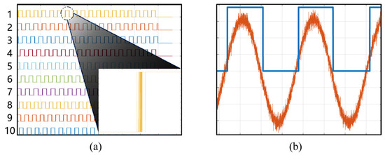
Figure 2.
(a) Conventional single-threshold triggering would introduce glitches. (b) The Schmitt trigger generates a square wave from the single-tone signal, with its inherent delay having no impact on frequency measurement.
The square wave frequency is
The end-to-end absolute latency of the nth channel, spanning from transmitter to receiver, is calculated in real-time within the FPGA:
where represents the number of square wave periods (typically ⩾8 for averaging to achieve better noise immunity), is the FPGA primary clock frequency for the accumulated counter, and CNT indicates the accumulated counter value over periods. Using Channel 1 as the reference, the relative delay compensation of all other channels can be calculated as follows:
In DBF-SAR systems, inter-channel time-delay errors primarily originate from asynchronous ADC sampling clocks during initialization. Taking a dual-phase ADC configuration as an example, the minimum clock misalignment unit is half the sampling clock period. Thus, the calibrated delay (in samples) is given by:
The integer part of is compensated by directly shifting sample points, while its fractional part is corrected via sinc interpolation. In IFDBF systems, employing digital delay elements for active time-delay compensation introduces a parasitic phase shift [28]. The parasitic phase requiring compensation is
where is the ADC sampling frequency. is not the original Intermediate Frequency (IF) sampled by the ADC, but rather its aliased “complex digital frequency” within the baseband principal interval under Nyquist sampling.
For example, with an ADC sampling rate of 1200 MHz and an input signal centered at = 900 MHz, the resulting becomes −300 MHz due to spectral folding, as illustrated in Figure 3:
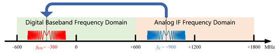
Figure 3.
Under Nyquist sampling, the observed complex frequency of a digital I/Q signal is constrained to its principal value range. A 900 MHz tone sampled at 1200 MHz appears aliased at −300 MHz.
After compensating for channel delay errors, all channels maintain temporal synchronization with Channel 1, each possessing the same propagation delay . When the signal passes through the calibration loop again, the dechirped signal of the nth channel is:
The Fourier transform enables high-precision computation of inter-channel phase differences.
However, even FFT operations impose high computational costs for FPGA-based real-time estimation of a long sampled sequence. Fortunately, the dechirped signal’s energy is predominantly concentrated in a single-tone component, thus permitting replacement of the full-spectrum FFT with a targeted DTFT computation at this specific frequency bin.
In practical implementations, the FPGA utilizes M-points’ discrete summation operations to approximate the continuous integration process.
Note that the discrete summation in DFT with finite points leads to different widths of spectral response. The half-power width of the main lobe for a single-tone frequency response is given by:
Normally, wider main lobes reduce frequency resolution in spectral estimation. However, the proposed method uses optimized short-window DTFT to improve error detection adaptability. For a spaceborne DBF-SAR system, the physical cable length L of the calibration signal path is known a priori. Although the actual signal path length differs from L by less than 1 meter, this deviation is within acceptable tolerance.
Under the simulation parameters described in Section 4 (sampling frequency = 1200 MHz, calibration signal chirp rate = Hz/s, M = 2000 sampling points, and reference length L = 10 m), the 3 dB bandwidth is approximately 531 kHz, whereas the reference frequency is around 333 kHz. Therefore, any single-tone signal between 67.5 kHz and 598.5 kHz falls within the effective detection range of the DTFT-based digital filter. The DTFT filter responses are illustrated in Figure 4.
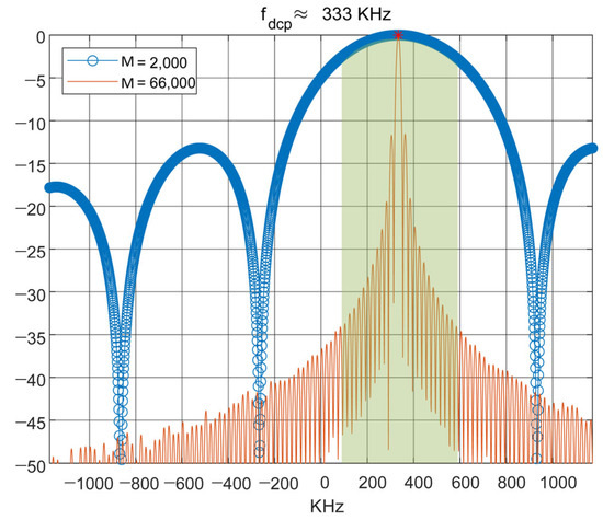
Figure 4.
A DTFT with fewer points exhibits a wider frequency bandwidth, enabling phase estimation across a broad range (green shaded area).
With reduced summation points, one DTFT detects all channels’ phase responses. The phase response of signal is derived via DTFT.
The phase error estimate for the nth channel is:
Omitting terms common to all channels simplifies the expression to:
The above equation demonstrates that accurate phase error estimation requires eliminating parasitic phase effects from two distinct sources: RF and IF. The RF parasitic phase arises from delay errors, while the IF parasitic phase is induced by active digital delay compensation.
The phase compensation value is:
The function maps angles exceeding to the principal value interval . This operation must be performed as the final step after absolute phase values from all channels have been obtained.
3. Real-Time Processing Architecture
During error estimation, only one channel’s signal is permitted to pass per PRF interval. The IFDBF signal flow diagram in Figure 5 indicates active channels with colored highlighting, while blocked signal paths remain uncolored.
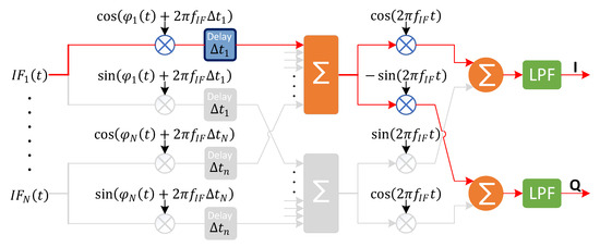
Figure 5.
Signal path during internal calibration error correction in IFDBF.
For an IFDBF architecture with N channels in elevation, the error estimation process comprises three sequential stages: amplitude, time delay, and phase. Each stage requires N consecutive PRFs to measure absolute errors from all N channels, followed by relative error and compensation value generation. The error correction diagram is shown in Figure 6.
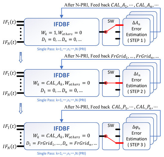
Figure 6.
Proposed error correction flow diagram.
The first step estimates amplitude errors. Only the calibrated k-th channel’s weight is set to 1, while all others are zero. After N PRIs to scan all channels, the amplitude compensation values ( to ) are fed back. The second step estimates time-delay errors. Here, only the k-th channel’s weight is set to (others are zero). After N-PRI (Pulse Repetition Interval) scanning, time-delay compensation values ( to ) are fed back. The third step estimates phase errors. The k-th channel’s weight remains (others zero), with all channels now applying pre-calibrated delays ( to ). After N-PRI scanning, phase compensation values ( to ) are fed back. The FPGA implementation architecture is illustrated in Figure 7.
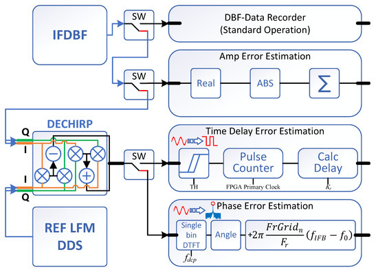
Figure 7.
Proposed FPGA implementation architecture.
The compensation methods for amplitude and phase errors in real-time IFDBF weight generation were introduced in [28]. As illustrated in Figure 8, the digital delay compensation employs distinct approaches for integer and fractional sample compensation. Integer-sample delays are implemented through direct data shifting. Fractional-sample delays are achieved using an 8-tap FIR filter with coefficients derived from sinc interpolation kernels sampled at 0/32, 1/32, 2/32, …, 31/32 intervals.
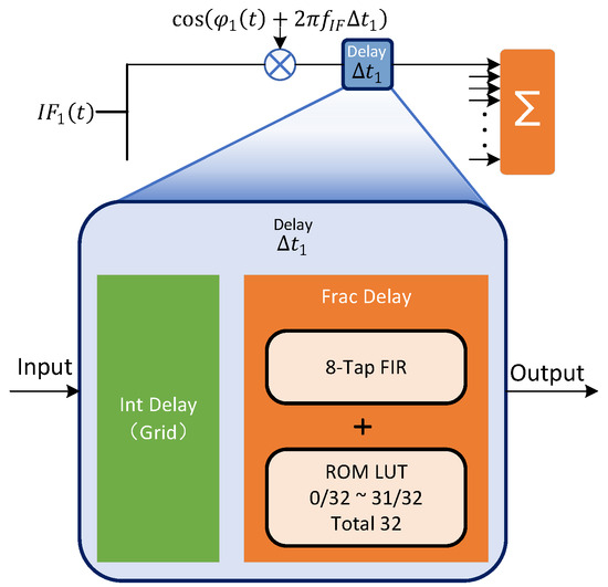
Figure 8.
Digital delay component with integer and fractional delay.
The Single bin DTFT implementation closely resembles the DBF process, as both involve time-varying weighting and summation of input signals. For DTFT, the weighting coefficients are generated by multiplying a constant term with a time-varying counter k to obtain the phase, followed by CORDIC [29] IP core-based computation of cosine/sine weights. The frequency response at is obtained by performing complex multiplication between the DTFT’s time-varying weights and the dechirped single-tone signal, followed by summation. The FPGA implementation block diagram of the Single bin DTFT is shown in Figure 9.
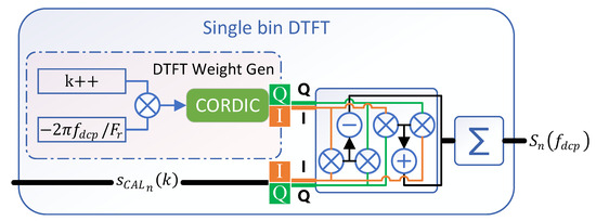
Figure 9.
FPGA implementation block diagram of the Single bin DTFT.
By estimating only a single channel’s error component per PRI, the design achieves significant resource sharing, reducing hardware implementation costs. The architecture utilizes: nine multipliers and two dividers, two CORDIC IP cores (including one dedicated to DTFT frequency response phase estimation) and one DDS IP core for signal generation.
4. Simulation and Experimental Results
This section presents simulation and experimental results to validate the performance of the proposed real-time multi-channel error calibration architecture. The impact of elevation multi-channel errors on DBF signal synthesis and imaging quality is also evaluated. The parameters of the simultated spaceborne DBF-SAR system are given in Table 1.

Table 1.
Simulation system parameters.
The ranges of randomly introduced amplitude, phase, and sample-grid time-delay errors are specified in Table 2.
Table 2.
Randomly introduced errors.
As shown in Equation (8), after dechirp processing, the complex frequency of the tone signal equals the negative product of the chirp rate and the absolute time delay of the internal calibration loop. Setting a negative chirp rate yields a positive complex frequency for this tone signal. Figure 10 presents the signal processing chain of the IF sampled signal (Figure 10a), including the sequential stages of (1) down-conversion via the IFDBF architecture (Figure 10b), (2) dechirping (Figure 10c), and (3) pulse shaping (Figure 10d). Since the internal calibration loop is designed with a 10 m reference length, the dechirped signal frequency is set to a reference value of 333 kHz.
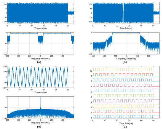
Figure 10.
(a) The IF sampled signal. (b) The down-converted baseband signal. (c) The dechirped signal. (d) The pulse-shaped signal.
The dechirp operation amplifies the sub-sample-grid errors (including half-grid offsets) through the chirp rate . Figure 11 demonstrates significant error estimation performance with zero residuals. The simulated internal calibration signal has an SNR of 20 dB. In practice, spaceborne SAR calibration loops typically show better SNR performance. Under the 20 dB SNR condition, the proposed algorithm achieves an amplitude error estimation residual within 0.1 dB and a phase error estimation residual within 1 degree. Higher SNR conditions can further improve error estimation performance. Multiple rounds of random error simulation show that the proposed architecture achieves precise and robust estimation of amplitude, phase, and time-delay errors.
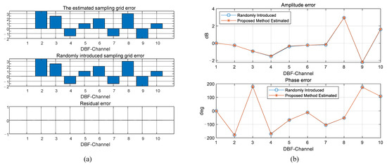
Figure 11.
(a) Sub-sample-grid time-delay error estimation results. (b) Amplitude and phase error estimation results.
Proper coherent synthesis of DBF signals can be prevented by amplitude, phase, and time-delay errors. In severe cases, coherent cancellation phenomena may even be caused by these errors. Figure 12 demonstrates the effects of point targets before and after channel error compensation. The simulation results demonstrate that due to incoherent signal superposition caused by channel errors, sideband raising and mainlobe broadening are observed in the point target response.
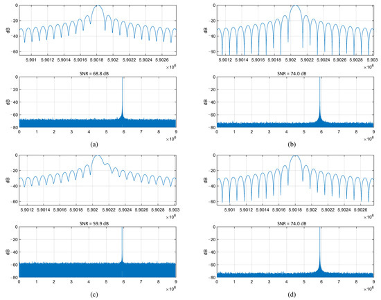
Figure 12.
Error correction effects on point target response and SNR. (a,c) DBF with channel error. (b,d) DBF after channel error calibration.
In addition to point target distortion, SNR degradation is another effect of channel errors on DBF systems. Given perfectly correlated signals, an N-channel DBF architecture yields an N-times SNR improvement. In this simulation case, the single-channel pulse-compressed SNR is approximately 64 dB. The 10-channel configuration provides a 10 dB gain. Figure 12a demonstrates a maintained SNR enhancement of 4.8 dB under amplitude-phase errors alone, excluding time-delay error components. Figure 12c demonstrates that when amplitude, phase, and time-delay errors coexist, the DBF-processed signal exhibits lower SNR than the single-channel output. Coherent cancellation effects further significantly distort the point target response. After error correction, the system can successfully reach its designed performance targets, as shown in Figure 12b,d.
To validate the effectiveness of the proposed error estimation algorithm and real-time processing architecture, experiments were conducted using a 16-channel X-band DBF-SAR system with an elevation of 16-channel capability. The raw data was acquired by an airborne SAR experimental system from the Aerospace Information Research Institute, Chinese Academy of Sciences (AIRCAS). The SAR system parameters are summarized in Table 3.
Table 3.
Experimental system parameters.
The imaging experiment scenario is located in a rural area, where strong scattering points are present within a weak background to observe the impact of channel errors on DBF imaging. The experimental results are shown in Figure 13. Figure 13a displays the uncorrected channel errors, where the point target exhibits significant defocusing along the range direction due to time delay errors between channels. Figure 13b demonstrates the corrected channel errors, showing well-focused point targets.
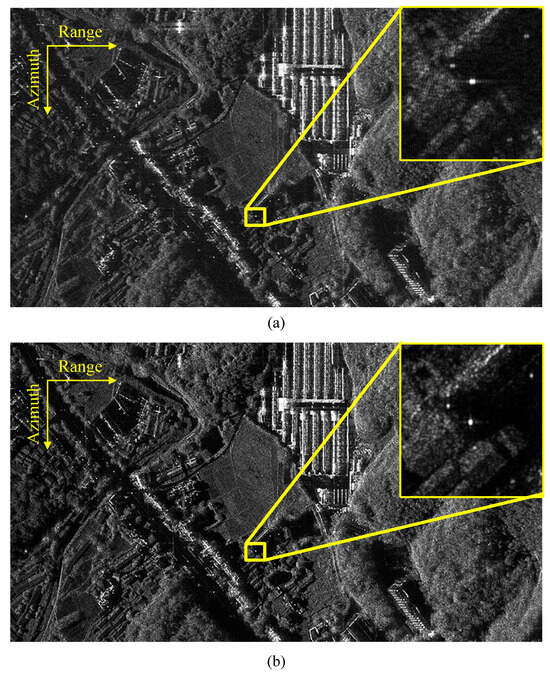
Figure 13.
Airborne DBF-SAR images (provided by the AIRCAS). (a) Before DBF multi-channel error calibration. (b) After DBF multi-channel error calibration.
5. Discussion
The proposed method discusses the IFDBF implementation case while remaining equally applicable to baseband Digital Beamforming (BBDBF) architecture [30]. Compared with BBDBF architecture, the IFDBF architecture significantly reduces the number of required filters, thereby decreasing implementation complexity [28,31]. The LFM was merely employed as a calibration tool, and the error-compensated system operates independently of the transmitted signal type. In fact, the proposed real-time multi-channel error estimation architecture is universally applicable to most multi-channel systems, including azimuth multi-channel, elevation multi-channel, and 2D multi-channel architectures. The IFDBF architecture inherently integrates amplitude, phase, and digital delay compensators to support its real-time complex weighting and time-delay operations. Only the error estimation module needs to be added, while the error compensation module can be shared with the DBF processing chain to conserve hardware resources. For other multi-channel systems such as the TerraSAR [32] azimuth multi-channel architecture, additional amplitude, phase, and time-delay error estimation and compensation modules must be incorporated.
The proposed method is inspired by the cal-tone technique [21,22,23], which estimates amplitude and phase errors through single-tone frequency analysis. Focusing on single-frequency spectral analysis significantly reduces the noise impact on error estimation. The proposed method generates a cal-tone-like single-tone signal via dechirp processing, but eliminates the need for additional RF components by implementing all necessary digital modules in an FPGA. Moreover, the method utilizes dechirp processing to estimate time-delay errors from single-tone frequency bias analysis, extending the functionality beyond conventional cal-tone techniques.
6. Conclusions
Digital beamforming serves as the cornerstone technology for next-generation spaceborne SAR systems to achieve HRWS imaging. The SNR improvement of DBF critically depends on inter-channel consistency. However, non-ideal channel matching introduces amplitude, phase, and time-delay errors due to thermal deformation and random synchronization errors among multi-channel ADCs. Conventional echo-based error estimation methods demonstrate satisfactory performance. However, the stringent real-time requirements imposed by DBF-SAR are not met. A novel real-time error calibration architecture, characterized by low cost and high estimation accuracy, is proposed in this paper. Although optimized for IFDBF real-time processing, the proposed multi-channel error calibration architecture can be widely applied to other spaceborne multi-channel systems requiring joint amplitude/phase/time-delay compensation. Simulation and experimental results validate the method’s effectiveness. In the future, we will continue to focus on implementing the SAR theory in practice.
Author Contributions
Conceptualization, J.Q. and W.W.; methodology, J.Q.; validation, J.Q. and S.H.; formal analysis, J.Q. and Y.F.; investigation, J.Q. and Z.Z.; resources, Z.Z. and Y.D.; data curation, Z.C.; writing original draft preparation, J.Q., S.H. and Y.F.; writing review and editing, J.Q., H.Z. and N.W. All authors have read and agreed to the published version of the manuscript.
Funding
This research was funded in part by the National Key Research and Development Program under Grant 2023YFB3904901 and in part by the next-generation ocean surveillance and monitoring technology (E5K8160106). (Corresponding author: Wei Wang.)
Data Availability Statement
The original contributions presented in this study are included in the articlel. Further inquiries can be directed to the corresponding author.
Acknowledgments
During the preparation of this manuscript, the author(s) used [DeepSeek, V3] for the purposes of [English grammar checking].
Conflicts of Interest
The authors declare no conflicts of interest.
Abbreviations
The following abbreviations are used in this manuscript:
| SAR | Synthetic Aperture Radar |
| DBF | Digital Beamforming |
| HRWS | High-Resolution Wide-Swath |
| IF | Intermediate Frequency |
| RF | Radio Frequency |
| PRF | Pulse Repetition Frequency |
| PRI | Pulse Repetition Interval |
| DTFT | Discrete-Time Fourier Transform |
| FPGA | Field-Programmable Gate Array |
| SNR | Signal-to-Noise Ratio |
| DDS | Direct Digital Synthesizer |
| I/Q | In-phase/Quadrature |
| LFM | Linear Frequency Modulation |
References
- Freeman, A.; Johnson, W.T.; Huneycutt, B.; Jordan, R.; Hensley, S.; Siqueira, P.; Curlander, J. The “Myth” of the minimum SAR antenna area constraint. IEEE Trans. Geosci. Remote Sens. 2002, 38, 320–324. [Google Scholar] [CrossRef]
- Zhang, Y.; Lu, P.; Wang, R. New insights into alternating transmitting mode (ATM) for bistatic multichannel SAR. IEEE Trans. Geosci. Remote Sens. 2024, 62, 5212716. [Google Scholar] [CrossRef]
- Gebert, N.; Krieger, G.; Moreira, A. Digital beamforming on receive: Techniques and optimization strategies for high-resolution wide-swath SAR imaging. IEEE Trans. Aerosp. Electron. Syst. 2009, 45, 564–592. [Google Scholar] [CrossRef]
- Krieger, G.; Gebert, N.; Moreira, A. Multidimensional waveform encoding: A new digital beamforming technique for synthetic aperture radar remote sensing. IEEE Trans. Geosci. Remote Sens. 2007, 46, 31–46. [Google Scholar] [CrossRef]
- Han, S.; Deng, Y.; Wang, W.; Zhao, Q.; Qiu, J.; Zhang, Y.; Chen, Z. A Novel Echo Separation Scheme for Space-Time Waveform-Encoding SAR Based on the Second-Order Cone Programming (SOCP) Beamformer. Remote Sens. 2022, 14, 5888. [Google Scholar] [CrossRef]
- Qiu, J.; Zhang, Z.; Chen, Z.; Han, S.; Wang, W.; Wen, Y.; Meng, X.; Fan, H. A novel real-time echo separation processing architecture for space–time waveform-encoding SAR based on elevation digital beamforming. Remote Sens. 2022, 14, 213. [Google Scholar] [CrossRef]
- Ferretti, A.; Prati, C.; Rocca, F. Permanent scatterers in SAR interferometry. IEEE Trans. Geosci. Remote Sens. 2002, 39, 8–20. [Google Scholar] [CrossRef]
- Berardino, P.; Fornaro, G.; Lanari, R.; Sansosti, E. A new algorithm for surface deformation monitoring based on small baseline differential SAR interferograms. IEEE Trans. Geosci. Remote Sens. 2003, 40, 2375–2383. [Google Scholar] [CrossRef]
- Farneti, E.; Cavalagli, N.; Venanzi, I.; Salvatore, W.; Ubertini, F. Residual service life prediction for bridges undergoing slow landslide-induced movements combining satellite radar interferometry and numerical collapse simulation. Eng. Struct. 2023, 293, 116628. [Google Scholar] [CrossRef]
- Calò, M.; Ruggieri, S.; Nettis, A.; Uva, G. A MTInSAR-based early warning system to appraise deformations in simply supported concrete girder bridges. Struct. Control Health Monit. 2024, 2024, 8978782. [Google Scholar] [CrossRef]
- Krieger, G.; Younis, M.; Gebert, N.; Huber, S.; Bordoni, F.; Patyuchenko, A.; Moreira, A. Advanced digital beamforming concepts for future SAR systems. In Proceedings of the 2010 IEEE International Geoscience and Remote Sensing Symposium, Honolulu, HI, USA, 25–30 July 2010; IEEE: Piscataway, NJ, USA, 2010; pp. 245–248. [Google Scholar]
- Zhou, Y.; Wang, W.; Chen, Z.; Lv, Z.; Han, X.; Liu, J.; Zhang, Q. Adaptive digital beamforming for SAR imaging in elevation. In Proceedings of the EUSAR 2022; 14th European Conference on Synthetic Aperture Radar, Leipzig, Germany, 25–27 July 2022; pp. 1–4. [Google Scholar]
- Liu, Y.; Cui, L.; Xu, Y.; Zhang, J.; Chen, Z.; Chen, G.; Xue, L.; Xu, L.; Chao, F.; Chen, J. A novel signal-cancellation-based channel phase bias calibration algorithm for spaceborne multi-channel HR WS SAR in azimuth. In Proceedings of the 2015 IEEE 5th Asia-Pacific Conference on Synthetic Aperture Radar (APSAR), Singapore, 1–4 September 2015; IEEE: Piscataway, NJ, USA, 2015; pp. 494–497. [Google Scholar]
- Xiao, F.; Ding, Z.; Li, Z.; Long, T. Channel error effect analysis for reconstruction algorithm in dual-channel SAR imaging. IEEE Geosci. Remote Sens. Lett. 2019, 17, 1563–1567. [Google Scholar] [CrossRef]
- Li, B.; Sun, G.; Xing, M. The Study on Range DBF Method for Real Data Processing. In Proceedings of the 2018 China International SAR Symposium (CISS), Shanghai, China, 10–12 October 2018; IEEE: Piscataway, NJ, USA, 2018; pp. 1–5. [Google Scholar]
- Younis, M.; Laux, C.; Al-Kahachi, N.; López-Dekker, P.; Krieger, G.; Moreira, A. Calibration of multi-channel spaceborne SAR-Challenges and strategies. In Proceedings of the EUSAR 2014, 10th European Conference on Synthetic Aperture Radar, Berlin, Germany, 3–5 June 2014; pp. 1–4. [Google Scholar]
- Wu, D.; Zhang, Y.; Zhu, D.; Wang, S.; Shen, M. A channel calibration algorithm based on isolated scatterers for multi-channel HRWS-SAR. IEEE Access 2019, 7, 135665–135677. [Google Scholar] [CrossRef]
- Liu, X.; Wang, J.; Zhao, W.; Cao, W.; Hou, X. A channel equalization approach using the spatial correlation property of clutters. In Proceedings of the IET International Radar Conference 2013, Xi’an, China, 14–16 April 2013; pp. 1–4. [Google Scholar]
- Zhou, Y.; Wang, R.; Deng, Y.; Yu, W.; Fan, H.; Liang, D.; Zhao, Q. A novel approach to Doppler centroid and channel errors estimation in azimuth multi-channel SAR. IEEE Trans. Geosci. Remote Sens. 2019, 57, 8430–8444. [Google Scholar] [CrossRef]
- Cai, Y.; Lu, P.; Li, B.; Li, J.; Chen, Y.; Wang, Y.; Nan, Y.; Wang, R.; Wu, Y. An efficient phase error calibration method for azimuth multichannel SAR based on least spectrum difference. IEEE Trans. Geosci. Remote Sens. 2024, 62, 5207213. [Google Scholar] [CrossRef]
- Hoffman, J.P.; Horst, S.; Perkovic, D.; Shaffer, S.; Ghaemi, H.; Veilleux, L. Advances in digital calibration techniques enabling real-time beamforming SweepSAR architectures. In Proceedings of the 2013 IEEE Aerospace Conference, Big Sky, MT, USA, 2–9 March 2013; IEEE: Piscataway, NJ, USA, 2013; pp. 1–9. [Google Scholar]
- Chuang, C.L.; Shaffer, S.; Smythe, R.; Niamsuwan, N.; Li, S.; Liao, E.; Lim, C.; Morfopolous, A.; Veilleux, L. DESDynI Quad First Stage Processor-a four channel digitizer and digital beam forming processor. In Proceedings of the 2013 IEEE Aerospace Conference, Big Sky, MT, USA, 2–9 March 2013; IEEE: Piscataway, NJ, USA, 2013; pp. 1–6. [Google Scholar]
- Younis, M.; Rommel, T.; de Almeida, F.; Huber, S.; Martone, M.; Villano, M.; Krieger, G. Investigations on the internal calibration of multi-channel SAR. In Proceedings of the 2017 IEEE International Geoscience and Remote Sensing Symposium (IGARSS), Fort Worth, TX, USA, 23–28 July 2017; IEEE: Piscataway, NJ, USA, 2017; pp. 5386–5389. [Google Scholar]
- Jäger, M.; Scheiber, R.; Reigber, A. External calibration of antenna pointing and positions in airborne sar systems. In Proceedings of the 2019 16th European Radar Conference (EuRAD), Paris, France, 2–4 October 2019; IEEE: Piscataway, NJ, USA, 2019; pp. 41–44. [Google Scholar]
- Song, M.; Yan, M.; Zhang, R.; Li, Q.; Wang, J. TI-ADC System Mismatch Error Estimation and Compensation. In Proceedings of the 2021 CIE International Conference on Radar (Radar), Haikou, China, 15–19 December 2021; IEEE: Piscataway, NJ, USA, 2021; pp. 2867–2870. [Google Scholar]
- Nguyen, M.P. Omega-K algorithm—A generalization for highly squinted spotlight SAR imaging with dechirp-on-receive. In Proceedings of the 2011 3rd International Asia-Pacific Conference on Synthetic Aperture Radar (APSAR), Seoul, Republic of Korea, 26–30 September 2011; pp. 1–4. [Google Scholar]
- Mizzoni, R.; Capece, P.; Contu, S.; Meschini, A.; Ivagnes, M.; Rosati, G. Antennas for observation, exploration and navigation in ThalesAleniaSpace-Italia: Past and present challenges. In Proceedings of the 2017 11th European Conference on Antennas and Propagation (EUCAP), Paris, France, 19–24 March 2017; pp. 1516–1520. [Google Scholar] [CrossRef]
- Qiu, J.; Zhang, Z.; Wang, R.; Wang, P.; Zhang, H.; Du, J.; Wang, W.; Chen, Z.; Zhou, Y.; Jia, H.; et al. A novel weight generator in real-time processing architecture of DBF-SAR. IEEE Trans. Geosci. Remote Sens. 2021, 60, 5204915. [Google Scholar] [CrossRef]
- Volder, J.E. The CORDIC Trigonometric Computing Technique. IRE Trans. Electron. Comput. 1959, EC-8, 330–334. [Google Scholar] [CrossRef]
- Feng, F.; Dang, H.; Tan, X.; Li, G.; Li, C. An improved scheme of Digital Beam-Forming in elevation for spaceborne SAR. In Proceedings of the IET International Radar Conference 2013, Xi’an China, 14–16 April 2013; pp. 1–6. [Google Scholar]
- Wang, W.; Wang, R.; Deng, Y.; Balz, T.; Hong, F.; Xu, W. An Improved Processing Scheme of Digital Beam-Forming in Elevation for Reducing Resource Occupation. IEEE Geosci. Remote Sens. Lett. 2016, 13, 309–313. [Google Scholar] [CrossRef]
- Torres, R.; Lokas, S.; Moller, H.; Zink, M.; Simpson, D. The TerraSAR-L mission and system. In Proceedings of the IGARSS 2004. 2004 IEEE International Geoscience and Remote Sensing Symposium, Anchorage, AK, USA, 20–24 September 2004; Volume 7, pp. 4519–4522. [Google Scholar] [CrossRef]
Disclaimer/Publisher’s Note: The statements, opinions and data contained in all publications are solely those of the individual author(s) and contributor(s) and not of MDPI and/or the editor(s). MDPI and/or the editor(s) disclaim responsibility for any injury to people or property resulting from any ideas, methods, instructions or products referred to in the content. |
© 2025 by the authors. Licensee MDPI, Basel, Switzerland. This article is an open access article distributed under the terms and conditions of the Creative Commons Attribution (CC BY) license (https://creativecommons.org/licenses/by/4.0/).