Abstract
In this work, we propose a geolocation framework for distant ground targets integrating laser rangefinder sensors with multimodal visual servo control. By simulating binocular visual servo measurements through monocular visual servo tracking at fixed time intervals, our approach requires only single-session sensor attitude correction calibration to accurately geolocalize multiple targets during a single flight, which significantly enhances operational efficiency in multi-target geolocation scenarios. We design a step-convergent target geolocation optimization algorithm. By adjusting the step size and the scale factor of the cost function, we achieve fast accuracy convergence for different UAV reconnaissance modes, while maintaining the geolocation accuracy without divergence even when the laser ranging sensor is turned off for a short period. The experimental results show that through the UAV’s continuous reconnaissance measurements, the geolocalization error of remote ground targets based on our algorithm is less than 7 m for 3000 m, and less than 3.5 m for 1500 m. We have realized the fast and high-precision geolocalization of remote targets on the ground under the high-altitude reconnaissance of UAVs.
1. Introduction
Unmanned Aerial Vehicles (UAVs) are widely utilized in Earth observation due to their scalability and integration with various sensor configurations [1,2]. Particularly, the combination of UAVs with multimodal vision sensors (including visible and infrared spectra) enables video-image information acquisition across various scenarios, meeting application requirements such as urban intelligent transportation systems, environmental field monitoring, and 3D scene reconstruction [3,4,5,6]. To accomplish these tasks, knowing the mapping relationship between targets in video sequences and their actual geospatial positions is often necessary, which necessitates visual-based target geolocation [7].
Visual-based target localization primarily falls into monocular vision [8,9,10] and multi-view vision approaches [11,12,13]. Monocular vision systems, lacking direct depth measurement capability, typically require geometric features of targets and reference objects for depth estimation [14]. Kim et al. implemented inertial measurement unit-based camera pose correction, transforming corrected frontal images to bird’s-eye view through inverse perspective mapping for target position, size, and orientation estimation [15]. You et al. generated simulated LiDAR point clouds from image data to obtain accurate pixel-level depth information [16]. Sun et al. developed an unsupervised learning-based depth estimation module combined with monocular image input for target localization [17]. While these methods demonstrated effectiveness on the KITTI dataset, their applicability remains constrained to targets within a 30 m range as per the KITTI dataset characteristics [18]. With further research, monocular vision has made significant breakthroughs in target localization in outdoor long-distance environments. Li et al. designed an outdoor monocular localization device achieving target positioning at 135 m through the fusion of multi-focal-length measurements [19]. Gao et al. proposed a soft correspondence constraint, weakening the coupling between detection and localization to increase the effective target localization distance of monocular vision outdoor targets to 150 m [20]. However, precise focal length calibration remains critical for monocular systems. Adjusting sensor focal length to enhance distant target features significantly amplifies localization errors, fundamentally limiting monocular vision’s capability for accurate long-range target localization.
In contrast, multi-view vision systems employ multiple vision sensors to observe targets simultaneously. These systems leverage pixel correspondences of identical targets across multiple images combined with sensor pose information for relative position deduction [21,22]. Xin et al. proposed a multi-UAV collaborative geolocalization method based on inertial navigation position information, which achieves the relative position inference of the target even when GPS information is unavailable, so that the localization results are not global, and the computed relative position information gradually loses its reliability as the IMU drifts [23]. Pan et al. proposed a moving target geolocalization method based on dual UAV vision, where they used two navigation-capable UAVs combined with multi-view geometry to estimate the target altitude to achieve target geolocalization within the UAV’s overhead field of view at a flight altitude of 100 m [24]. Sun et al. created an air–ground collaborative geolocation system (AGCG) that employs ground-based stereo vision to guide UAV alignment, achieving 4.4 m average accuracy at 300 m range through GPS-based tracking [25]. Liu et al. used the target position information as the control signal, servo-controlled two ground cameras with known geographic locations to align with the target, solved the precise geographic location of the target based on the camera attitude rotation angle, and achieved geolocalization of a 1200 m long-distance target with an error of 3.5% [26]. While multi-view methods overcome focal length constraints of long-range geolocation, they typically require precise calibration before measurements.
The vast majority of the visual localization methods mentioned above use a local coordinate system to represent the target location, which greatly limits the connection between observations. The UAV’s own GPS information is readily available, so UAV-based visual localization methods can achieve global geolocation [27]. In recent years, aerial remote sensing image small target recognition technology and multimodal image target recognition technology have made great progress [28,29,30,31]. The wide application of the electro-optical stabilization and tracking platform (EOSTP) and Micro-Electro-Mechanical System (MEMS) inertial attitude measurement system in UAV platforms [32,33,34] has led to significant improvement in the attitude control accuracy of UAV payloads. In this paper, the UAV payload is servo-controlled to keep the center of the multimodal image always aligned with the target. Global geolocalization of remote ground targets is performed by combining the UAV moment-knowable GPS information and UAV payload attitude information. The main innovations of this paper are as follows:
- A UAV visual geolocalization framework based on multimodal visual servoing is proposed, which is combined with UAV GPS information to achieve global geo-localization of remote targets on the ground;
- The hardware framework requires only one initial calibration after the assembly is completed and does not need to be calibrated again before each subsequent measurement, which greatly improves the positioning efficiency.
- The stepped localization convergence model improves the robustness to abnormal measurement interference based on ensuring the convergence speed of localization accuracy.
2. Materials and Methods
2.1. Materials
Based on our previous related research [35], we use the same hardware framework in this paper. As shown in Figure 1, we use an ASN-216 vertical take-off and landing (VTOL) UAV for continuous reconnaissance of ground targets, employing image-based visual servo control of the UAV payload to always keep the ground target in the center of the field of view. We systematically record UAV GPS coordinates, payload attitude parameters, and laser-measured target distances throughout this process. Notably, the UAV’s maximum operational altitude reaches 5000 m with an effective control range of 8000 m. The computer platforms used in this paper are CPU I7-9700 (Intel, City of Santa Clara, CA, USA) and GPU GTX2070S (NVIDIA, City of Santa Clara, CA, USA), and the errors of each sensor of the UAV platform are shown in Table 1. The frequency of visual image and other measurement data acquisition is 25 times/second.
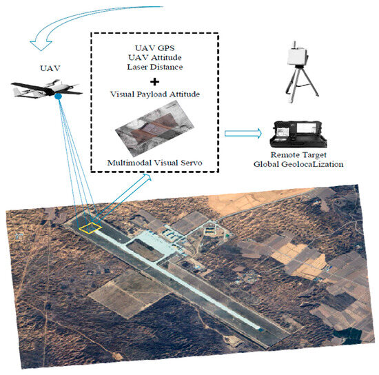
Figure 1.
Schematic of UAV remote target geolocalization based on multimodal visual servo.

Table 1.
Error of each sensor of the UAV platform.
We use the UAV multimodal vision servo module [32] to control the UAV payload to continuously measure remote targets on the ground. The binocular vision measurement of the VSG algorithm requires binocular alignment before each measurement, whereas our method requires only one calibration to obtain the attitude correction parameters after the hardware assembly is completed. No additional calibration is required for each measurement on the premise that the sensors of the UAV do not undergo drastic collision displacement, which greatly improves the efficiency of mission execution. Continuous monocular visual servo measurements provide sufficient data for more accurate remote target geolocation, and to take advantage of continuous measurements more efficiently, we design a stepped-convergence target geolocation optimization method. In this section, our proposed method is described in detail.
2.2. Global Geolocation Model
In the study of Liu et al. [26], the transformation relationship between the global geographic coordinate system and the local geographic coordinate system, denoted as in this paper, is derived in detail. Based on that, we introduce a laser ranging sensor to measure the distance from the target to the visual sensor, based on which we get rid of the dependence of visual geolocalization on the accurate focal length information of the visual sensor.
We can obtain the position of the UAV under the localized geographic coordinate system from the UAV’s GPS information :
The position of a ground target in the local coordinate system can be defined by the laser-measured distance transformed by two attitude rotations:
where is the inverse transformation of the UAV attitude rotation matrix. is the inverse transformation of the UAV payload attitude rotation matrix. is the laser measurement distance. The UAV attitude and payload attitude rotation matrices are:
is the UAV heading angle, is the UAV pitch angle, and θ is the UAV roll angle. is the rotational azimuth of the photoelectric load; is the pitch angle of the photoelectric load. The lower right corner labels represent the sine function (s) and cosine function (c), respectively. The latitude, longitude, and altitude of the target can be obtained by converting the results calculated in Equation (2) to the global geographic coordinate system.
2.3. Attitude Error Calibration
The accuracy of a UAV’s attitude is critical for ground target localization. We calibrate the system installation error by tracking measurements of known target points to improve the system’s localization accuracy for unknown targets. The exact location of the target is known and converted to a local geographic coordinate system expressed as . The system’s estimate of the position of this target point at moment is:
Simultaneous Taylor series expansion of the position estimates for moments and can be obtained:
Solving the matrix equation gives a one-step estimate of the attitude angle and corrects the attitude measurements at moment and moment .
Substitute the corrected attitude angle into Equation (6) until the th iteration lets . At this point, an estimate of the attitude angle mounting error at moment is obtained . The attitude angle mounting error of the system is obtained by averaging the error estimates from multiple moments over a period of time.
The calibration parameters obtained here are applicable to each measurement process, and the whole sensor system does not need to be calibrated repeatedly when geolocalizing different targets, which greatly exploits the convenience of UAVs performing tasks in the air.
2.4. Fast Step Convergence Model
Gaussian Newton method [36] has strong local convergence ability in solving least squares problems, and target geolocalization based on continuous reconnaissance measurements by UAVs is a typical least squares problem. Least squares is a mathematical optimization technique. It searches for the best function match of the data by minimizing the sum of squares of the errors. In the target positioning, three-dimensional coordinate information error optimization solution has a similarity. The selected target positioning with the x-axis information requires the following analysis, and the error function in the least squares problem in solving the target coordinates can be defined as
Here, the first order Taylor expansion of the error function is performed, and the optimization objective function after the expansion is
where is the Jacobi matrix of , the only variable in Equation (11) is , and is a definite value, so Equation (11) is a quadratic function with as a variable. Therefore, this function has a minimum value, and the condition for its minimum value is that the derivative of this equation with respect to is zero.
Let , . Then, the incremental equation for the Gaussian Newton method is:
In solving , it is necessary to compute . has only semi-positive definite properties, and in the actual computation may be a singular matrix, when is unstable and the algorithm fails to converge.
However, the Gaussian Newton method is extremely sensitive to the initial guess value, and when the initial prediction seriously deviates from the true position of the target, the Gaussian Newton method will not be able to converge to the global optimal solution. In the face of possible anomalous measurements, the Gaussian Newton method will fall into the local optimum due to the lack of global search capability, resulting in large target localization errors. In order to cope with the problem of the non-convergence of the Gaussian Newton method due to local data anomalies encountered in practical calculations, while retaining the characteristics of fast local convergence of the Gaussian Newton method, this paper is inspired by the Gaussian Newton method using the gradient to predict the minimum coordinate value of the error and proposes a fast stepwise convergence method for the geolocalization of the target.
First, we sampled 100 sets of measurements at equal intervals from the continuous measurement global data, where the th set of the data is denoted as , . and denote the UAV attitude and payload attitude of the extracted measurements. The initial target localization estimate and UAV measurements of the system at moment are . The distance error function and angle error function are defined as follows:
where is the distance error scale factor, and is the angle error scale factor. They are represented by the attitude measurement variance and the laser measurement distance variance of the extracted measurements. The distance error function and angle error function are combined to construct the error loss function.
Calculate the cost function for the original predicted coordinates and the stepping coordinates , , , , , , and , respectively. Compare the coordinate cost function values of each step and take the coordinate value with the smallest cost function value as the final predicted coordinate value.
We set a fixed iteration step size so that the target geolocalization error can only dissipate in iteration steps at the fastest rate in the case of anomalous data measurements, and the system still has the ability to converge quickly after new valid data inputs. Such an iterative approach makes full use of the available historical observations to predict the geographic location of the target.
3. Results
In the previous section, we presented a fast stepwise convergence algorithm for high-precision geolocalization of UAV remote targets. In this section, in order to evaluate the performance of our proposed algorithm in an all-around way, we use three different UAV reconnaissance modes to geolocalize targets at different geographic locations, respectively.
3.1. Experiments’ Setup
As shown in Figure 2, our experimental site is located at an airfield in the northern region of Shaanxi Province, China. We set up a total of six sets of experiments involving three UAV reconnaissance modes and two different imaging sensors. The differential GPS localization value of the target is used as the reference value in the experiment. The DGPS accuracy is <0.5 m horizontal, <0.5 m vertical with an update rate of five times per second. In static target geolocalization scenarios, the target position is considered to be unchanging over time, so the differential GPS reference can be interpolated to ensure that the RMSE is based on consistent time-aligned truth values. We compare the current publicly available optimal algorithm for outdoor long-range geolocalization, VSG [24], but this method is only applicable to a single measurement. We improved the VSG using the Gaussian Newton method [34] so that it can effectively utilize the continuous measurement data to make the target geolocation results more accurate. In six extensive sets of experiments, we compared VSG, VSG + G-N, and different preset parameters of our method.
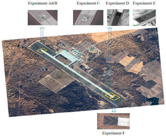
Figure 2.
Experimental sites.
We set up Experiment A and Experiment B as a free circling reconnaissance of ground targets by the UAV using a visible vision sensor, during which the laser ranging sensor was briefly turned off. We used the UAV to perform free circling reconnaissance of ground targets at an altitude of 2400 m, with a hovering radius of 1100 m. The UAV flight trajectory and laser-measured distance in Experiment A are shown in Figure 3a and Figure 4a. The UAV flight trajectory and laser-measured distance in Experiment B are shown in Figure 3b and Figure 4b.
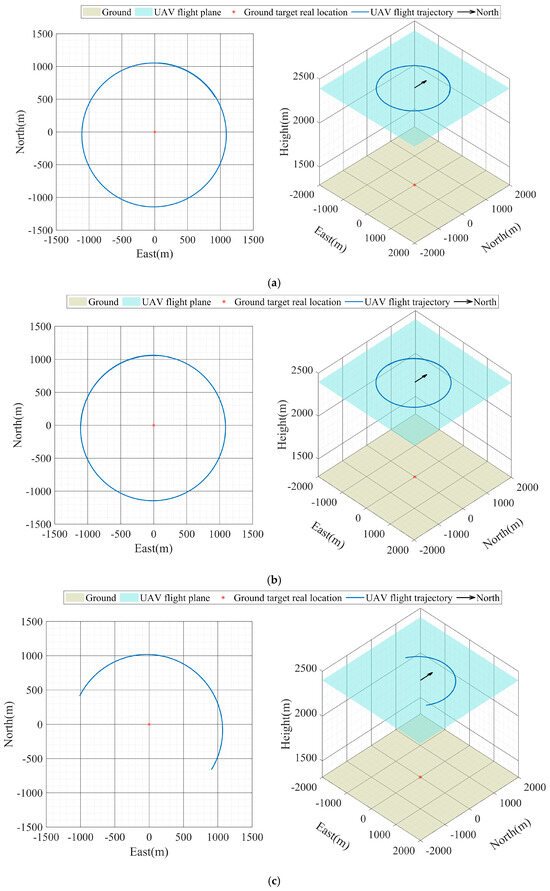
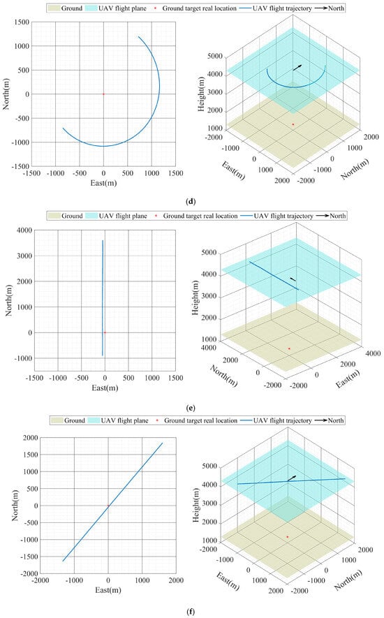
Figure 3.
UAV flight trajectory (a) UAV flight trajectory of Experiment A, (b) UAV flight trajectory of Experiment B, (c) UAV flight trajectory of Experiment C, (d) UAV flight trajectory of Experiment D, (e) UAV flight trajectory of Experiment E, (f) UAV flight trajectory of Experiment F.
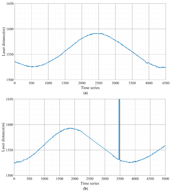
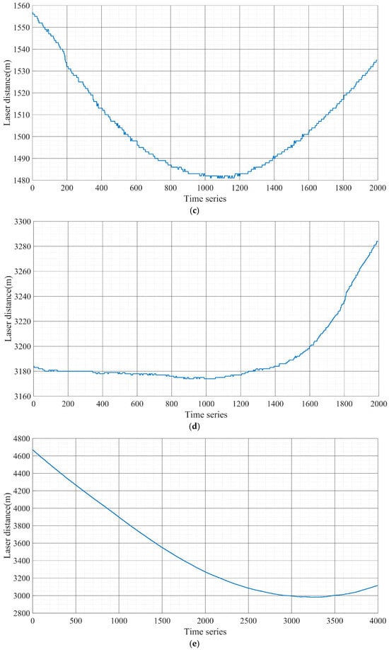
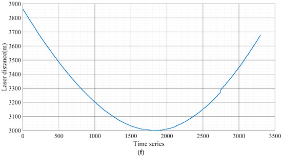
Figure 4.
Laser measured distance (a) Laser measured distance of Experiment A, (b) Laser measured distance of Experiment B, (c) Laser measured distance of Experiment C, (d) Laser measured distance of Experiment D, (e) Laser measured distance of Experiment E, (f) Laser measured distance of Experiment F.
Experiments C and D use visible vision sensors and infrared vision sensors, respectively, to geolocalize targets and simulate potential manned–unmanned cooperative scenarios. Manned–unmanned cooperative scenarios are prevalent in the military domain. In this case, the UAV is between a ground target and a manned aircraft and uses a laser to continuously illuminate the target to provide guidance to the manned aircraft. During the mission, the UAV also provides cover for the manned aircraft, which limits the effective activity area of the UAV. The UAV flight trajectory and laser-measured distance in Experiment C are shown in Figure 3c and Figure 4c. The UAV flight trajectory and laser-measured distance in Experiment D are shown in Figure 3d and Figure 4d.
Experiments E and F used infrared vision sensors and visible vision sensors to geolocalize ground targets, respectively. In both sets of experiments, the UAV performs reconnaissance measurements of the target in a fly-over mode directly over the target at an altitude of 4300 m. The UAV flight trajectory and laser-measured distance in Experiment E are shown in Figure 3e and Figure 4e. The UAV flight trajectory and laser-measured distance in Experiment F are shown in Figure 3f and Figure 4f.
3.2. Experiments’ Results
In order to evaluate the performance of our proposed algorithm in all aspects, we present four sets of step sizes in each set of experiments. Figure 5 and Figure 6 show the results for each of the six sets of experiments. Our method achieves the highest target geolocalization accuracy in all six sets of experiments. Moreover, our method has the fastest accuracy convergence rate as well as higher stability.
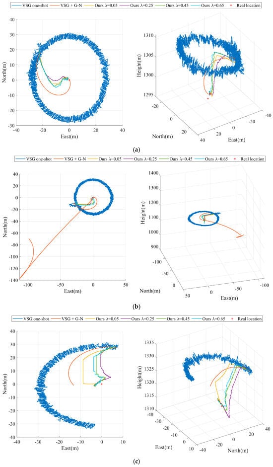
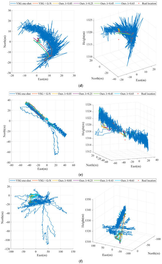
Figure 5.
Comparison of the convergence process of geolocalization with different ladder step sizes (a) Experiment A, (b) Experiment B, (c) Experiment C, (d) Experiment D, (e) Experiment E, (f) Experiment F.
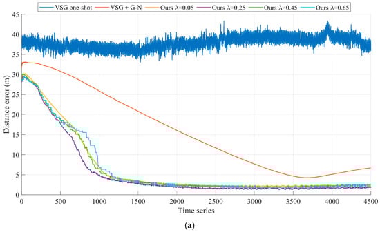
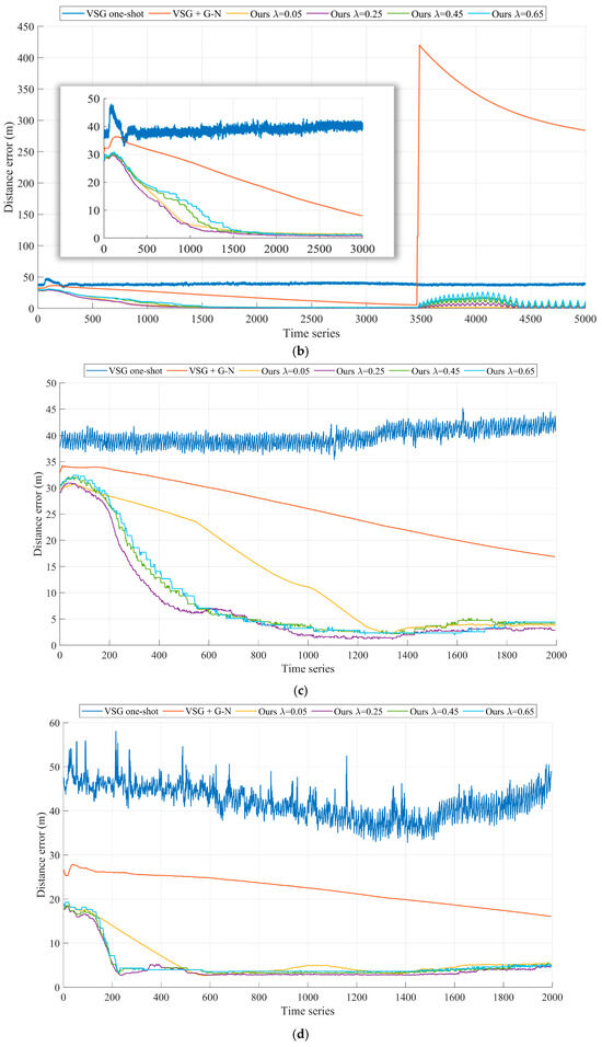
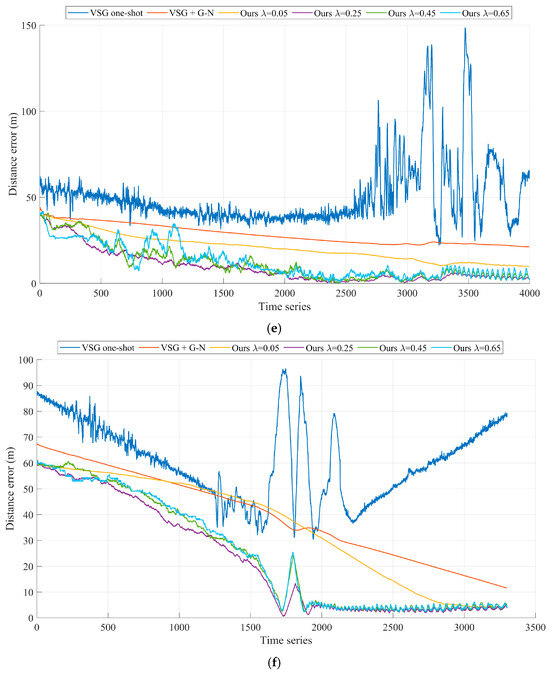
Figure 6.
Comparison of geolocalization errors with different ladder step sizes (a) Experiment A, (b) Experiment B, (c) Experiment C, (d) Experiment D, (e) Experiment E, (f) Experiment F.
As shown in Figure 5a and Figure 6a, our algorithm performs optimally with the preset parameter of in Experiment A. After tracking measurements on ground targets for 40 s (the 1000th set of time series), the geolocalization accuracy of our method for remote targets on the ground converges to 5 m and stably maintains itself within this accuracy thereafter. As shown in Figure 6b, before and after briefly turning off and then on the laser ranging sensor in Experiment B, the experimental results exhibit two different convergence results. The experimental results before the 3000th set of time series are similar to those in Experiment A. During the second convergence process, the different preset parameters of our algorithm exhibit convergence again, where the optimal preset parameter is . This is due to the fact that the smaller convergence step size greatly limits the target geolocalization drift when experiencing measurement disturbances. The VSG + G-N method, which is affected by Gaussian Newton algorithms, is trapped in a local optimum and cannot be corrected back to a reasonable range in a short period of time. The VSG method does not use laser range sensors to participate in the geolocalization of the ground targets and therefore is not disturbed by laser range sensor errors.
As shown in Figure 5c and Figure 6c, our algorithm performs optimally with the preset parameter of in Experiment C. After tracking measurements on ground targets for 24 s (the 600th set of time series), the geolocalization accuracy of our method for remote targets on the ground converges to 7 m and stably maintains itself within this accuracy thereafter. As shown in Figure 5d and Figure 6d, the VSG method exhibits greater volatility in Experiment D. This is due to the fact that Experiment D uses the infrared vision sensor as a benchmark for target geolocalization. Compared to the target recognition task based on visible sensors, the target recognition task based on infrared vision sensors is more difficult at long distances. At this time, the laser distance measurement is more reliable in target geolocalization than UAV payload attitude angle. The experimental results show that the optimal preset parameter of our algorithm is .
In both Experiment E and Experiment F, the UAV is in a reconnaissance mode flying directly above the target, simulating the potential military bombing scenario. Combining Figure 4f and Figure 6f, we can find that the geolocalization accuracy of the target fluctuates significantly when the UAV is directly above the target, i.e., near the 1800th set of time series. This is due to the Eulerian angle deadlock of the UAV payload in the positive downward view, when the reliability of the attitude angle information of the UAV payload is weaker than that of the laser measurement of the distance. In Experiment E, our algorithm performs best with the preset parameter of . As shown in Figure 4e and Figure 6e, the results of Experiment E present the same phenomenon.
Table 2 counts the target geolocalization errors of each algorithm in the six sets of experiments. In these six sets of experiments, the preset parameter that reflects the optimal performance of our algorithm is . We use the root mean square error (RMSE) to characterize the target geolocation error. The statistical interval for Experiment A is from the 1001st frame to the 4500th frame of data. It is worth noting that Experiment B has two convergence processes, and the statistical interval of Experiment B(a) is from the 1001st frame to the 3000th frame of data. The statistical interval of Experiment B(b) is from frame 3001 to frame 5000 of data. Due to the presence of anomalous measurements interfering, the best performance is exhibited with the preset parameter . The statistical interval of Experiment C is from frame 601 to frame 2000 of the data. The statistical intervals for Experiment D are from the 201st frame to the 2000th frame of data. The statistical interval of Experiment E is from frame 1501 to frame 4000. The statistical interval of Experiment F is from frame 1501 to frame 3300. The results of Experiment D and Experiment E show that our method is still advantageous in infrared vision sensor systems.
Table 2.
Comparison of the target localization error of each algorithm.
4. Discussion
Although our method showed the best performance in all six sets of experiments, analyzing the effects of different preset parameter combinations on the target geolocation accuracy is crucial for our subsequent research work.
Among the preset parameters we set, the distance error scaling factor and the angle error scaling factor affect the weights of the distance error function and the angle error function in the loss cost function, respectively. When the error proportion coefficient is larger and the angular error proportion coefficient is smaller, the angular error function in the loss cost function has a larger weight. It can be seen from Figure 7. At this time, the localization convergence process presents vertical priority over the horizontal position. The system is suitable for scenarios with better attitude-angle reliability, such as Experiments A, B, C and D. Correspondingly, when the error proportion coefficient is smaller and the angular error proportion coefficient larger, the distance error function in the loss cost function has a larger weight, and then the system is suitable for scenarios with better reliability of laser ranging, such as Experiments E and F.
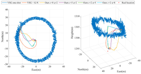
Figure 7.
Comparison of geolocalization errors with different scale factors.
The results in Figure 6 and Figure 8 and Table 2 show that the larger step size target geolocalization accuracy converges faster but is less stable when anomalous measurements interfere than the smaller step size control group. Such a characteristic suggests that we can develop a step-size adaptive strategy in engineering applications to achieve robust maintenance of the converged accuracy by changing the step-size after converging to a certain accuracy for target geolocalization.
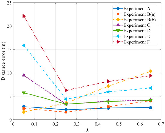
Figure 8.
Parameter scan plots.
5. Conclusions
In this paper, we propose a multimodal visual servo-based framework for UAV geolocalization of remote targets on the ground. By introducing a laser ranging sensor, we get rid of the dependence on the accurate focal length of the visual sensor. The experimental results show that we achieve global geolocalization of remote targets above 3000 m with a localization error of less than 7 m.
However, our current high-precision multimodal visual servo-based geolocation framework remains applicable solely to stationary targets. Practical mission scenarios further require geolocation and motion state estimation for moving ground targets at extended ranges. Based on our framework, new challenges will be faced if geolocalizing ground-based remote motion targets, such as visual servo tracking of remote motion targets, is more difficult. How to realize high-precision geo-localization and motion state estimation for ground-based remote motion targets will be our future research direction.
Author Contributions
Conceptualization, X.Z.; methodology, X.Z., R.H. and W.J.; software, X.Z.; validation, X.Z. and H.L.; formal analysis, X.Z. and Y.M.; investigation, X.Z.; resources, X.Z., H.L. and Y.M.; data curation, X.Z.; writing—original draft preparation, X.Z.; writing—review and editing, X.Z. and W.S.; visualization, X.Z. and R.H.; supervision, X.Z. and W.S.; project administration, W.S.; funding acquisition, W.S. All authors have read and agreed to the published version of the manuscript.
Funding
This paper was funded by the National Natural Science Foundation of China 62173330, 62371375; the Shaanxi Key R&D Plan Key Industry Innovation Chain Project (2022ZDLGY03-01); the China College Innovation Fund of Production, Education and Research (2021ZYAO8004); the Xi’an Science and Technology Plan Project (2022JH-RGZN-0039); and the Fundamental Research Funds for the Central Universities (ZYTS25245).
Data Availability Statement
The raw data supporting the conclusions of this article will be made available by the authors upon request.
Conflicts of Interest
Authors Hongjuan Liu and Yuanchao Ma were employed by the company Xi’an ASN Technology Group Co., Ltd. The remaining authors declare that the research was conducted in the absence of any commercial or financial relationships that could be construed as a potential conflict of interest.
Abbreviations
The following abbreviations are used in this manuscript:
| UAV | Unmanned Aerial Vehicle |
| EOSTP | Electro-optical stabilization and tracking platform |
| MEMS | Micro-Electro-Mechanical System |
| VOTL | Vertical take-off and landing |
References
- Zhang, Z.; Huang, L.; Wang, Q.; Jiang, L.; Qi, Y.; Wang, S.; Shen, T.; Tang, B.H.; Gu, Y. UAV Hyperspectral Remote Sensing Image Classification: A Systematic Review. IEEE J. Sel. Top. Appl. Earth Obs. Remote Sens. 2025, 18, 3099–3124. [Google Scholar] [CrossRef]
- Zhang, Z.; Zhu, L. A Review on Unmanned Aerial Vehicle Remote Sensing: Platforms, Sensors, Data Processing Methods, and Applications. Drones 2023, 7, 398. [Google Scholar] [CrossRef]
- Wan, S.; Xu, X.; Wang, T.; Gu, Z. An intelligent video analysis method for abnormal event detection in intelligent transportation systems. IEEE Trans. Intell. Transp. Syst. 2021, 22, 4487–4495. [Google Scholar] [CrossRef]
- Liu, Z.; Lu, D.; Qian, W.; Ren, K.; Zhang, J.; Xu, L. Vision-based inter-vehicle distance estimation for driver alarm system. IET Intell. Transp. Syst. 2019, 13, 927–932. [Google Scholar] [CrossRef]
- He, A.; Li, X.; Wu, X.; Su, C.; Chen, J.; Xu, S.; Guo, X. ALSS-YOLO: An Adaptive Lightweight Channel Split and Shuffling Network for TIR Detection in UAV Imagery. IEEE J. Sel. Top. Appl. Earth Obs. Remote Sens. 2024, 17, 17308–17326. [Google Scholar] [CrossRef]
- Yang, S.; Scherer, S. CubeSLAM: Monocular 3-D object SLAM. IEEE Trans. Robot. 2019, 35, 925–938. [Google Scholar] [CrossRef]
- Chabot, F.; Chaouch, M.; Rabarisoa, J.; Teuliere, C.; Chateau, T. Deep MANTA: A coarse-to-fine many-task network for joint 2D and 3D vehicle analysis from monocular image. In Proceedings of the IEEE Conference on Computer Vision and Pattern Recognition, Honolulu, HI, USA, 21–26 July 2017; pp. 2040–2049. [Google Scholar]
- Ding, M.; Chen, W.-H.; Cao, Y.-F. Thermal infrared single-pedestrian tracking for advanced driver assistance system. IEEE Trans. Intell. Veh. 2023, 8, 814–824. [Google Scholar] [CrossRef]
- Lee, C.; Seo, H.; Kim, H.J. Position-based monocular visual servoing of an unknown target using online self-supervised learning. In Proceedings of the 2019 IEEE/RSJ International Conference on Intelligent Robots and Systems (IROS), Macau, China, 3–8 November 2019; pp. 4467–4473. [Google Scholar]
- Park, J.; Kim, T.; Kim, J. Model-referenced pose estimation using monocular vision for autonomous intervention tasks. Auto. Robot. 2020, 44, 205–216. [Google Scholar] [CrossRef]
- Yan, J.; Zhang, Y.; Kang, B.; Lun, D.P.-K. Multiple binocular cameras-based indoor localization technique using deep learning and multimodal fusion. IEEE Sens. J. 2022, 22, 1597–1608. [Google Scholar] [CrossRef]
- Yu, Z.; Ma, Y.; Zhou, Y.; Wang, C.; Li, Q. A binocular stereo visual servo system for bird repellent in substations. Multimed. Tools Appl. 2023, 82, 29353–29377. [Google Scholar] [CrossRef]
- Zhang, J.; Liu, Z.; Gao, Y.; Zhang, G. Robust method for measuring the position and orientation of drogue based on stereo vision. IEEE Trans. Ind. Electron. 2021, 68, 4298–4308. [Google Scholar] [CrossRef]
- Pan, T.; Deng, B.; Dong, H.; Gui, J.; Zhao, B. Monocular-Vision-Based Moving Target Geolocation Using Unmanned Aerial Vehicle. Drones 2023, 7, 87. [Google Scholar] [CrossRef]
- Kim, Y.; Kum, D. Deep learning based vehicle position and orientation estimation via inverse perspective mapping image. In Proceedings of the 2019 IEEE Intelligent Vehicles Symposium (IV), Paris, France, 9–12 June 2019; pp. 317–323. [Google Scholar]
- You, Y.; Wang, Y.; Chao, W.L.; Garg, D.; Pleiss, G.; Hariharan, B.; Campbell, M.; Weinberger, K.Q. Pseudo-LiDAR++: Accurate depth for 3D object detection in autonomous driving. In Proceedings of the International Conference on Learning Representations, Virtual Only Conference, 26 April–1 May 2020. [Google Scholar]
- Sun, L.; Yin, W.; Xie, E.; Li, Z.; Sun, C.; Shen, C. Improving monocular visual odometry using learned depth. IEEE Trans. Robot. 2022, 38, 3173–3186. [Google Scholar] [CrossRef]
- Geiger, A.; Lenz, P.; Stiller, C.; Urtasun, R. Vision meets robotics: The KITTI dataset. Int. J. Robot. Res. 2013, 32, 1231–1237. [Google Scholar] [CrossRef]
- Li, L.; Deng, F.; Gao, F. Outdoor long-range target positioning based on multi-monocular vision fusion. In Proceedings of the 2020 Chinese Automation Congress (CAC), Shanghai, China, 6–8 November 2020; pp. 5273–5278. [Google Scholar]
- Gao, F.; Deng, F.; Li, L.; Zhang, L.; Zhu, J.; Yu, C. MGG: Monocular global geolocation for outdoor long-range targets. IEEE Trans. Image Process. 2021, 30, 6349–6363. [Google Scholar] [CrossRef]
- Deng, F.; Zhang, L.; Gao, F.; Qiu, H.; Gao, X.; Chen, J. Long-range binocular vision target geolocation using handheld electronic devices in outdoor environment. IEEE Trans. Image Process. 2020, 29, 5531–5541. [Google Scholar] [CrossRef] [PubMed]
- Zhang, Z.; Li, N.; Yan, G.; Li, W. The development of distributed cooperative localization algorithms for Multi-UAV systems in the past decade. Measurement 2025, 256, 118040. [Google Scholar] [CrossRef]
- Xin, X.; Pan, F.; Wang, Y.; Feng, X. Multi-UAV Cooperative Localization Using Adaptive Wasserstein Filter with Distance-Constrained Bare Bones Self-Recovery Particles. Drones 2024, 8, 234. [Google Scholar] [CrossRef]
- Pan, T.; Gui, J.; Dong, H.; Deng, B.; Zhao, B. Vision-Based Moving-Target Geolocation Using Dual Unmanned Aerial Vehicles. Remote Sens. 2023, 15, 389. [Google Scholar] [CrossRef]
- Sun, Z.; Liu, Y.; Zhang, L.; Deng, F. AGCG: Air–Ground Collaboration Geolocation Based on Visual Servo with Uncalibrated Cameras. IEEE Trans. Ind. Electron. 2024, 71, 14410–14419. [Google Scholar] [CrossRef]
- Liu, Y.; Sun, Z.; Wang, X.; Fan, Z.; Wang, X.; Zhang, L.; Fu, H.; Deng, F. VSG: Visual Servo Based Geolocalization for Long-Range Target in Outdoor Environment. IEEE Trans. Intell. Veh. 2024, 9, 4504–4517. [Google Scholar] [CrossRef]
- Zhang, F.; Yang, T.; Bai, Y.; Ning, Y.; Li, Y.; Fan, J.; Li, D. Online ground multitarget geolocation based on 3-D map construction using a UAV platform. IEEE Trans. Geosci. Remote Sens. 2022, 60, 5621817. [Google Scholar] [CrossRef]
- Zhang, H.; Sun, W.; Sun, C.; He, R.; Zhang, Y. HSP-YOLOv8: UAV Aerial Photography Small Target Detection Algorithm. Drones 2024, 8, 453. [Google Scholar] [CrossRef]
- Wang, D.; Gao, Z.; Fang, J.; Li, Y.; Xu, Z. Improving UAV Aerial Imagery Detection Method via Superresolution Synergy. IEEE J. Sel. Top. Appl. Earth Obs. Remote Sens. 2025, 18, 3959–3972. [Google Scholar] [CrossRef]
- Gao, H.; Yan, Y.; He, Y.; Zhou, J.; Zhang, Z.; Yang, Y. CAIL: Cross-Modal Vehicle Reidentification in Aerial Images Using the Centroid-Aligned Implicit Learning Network. IEEE J. Sel. Top. Appl. Earth Obs. Remote Sens. 2025, 18, 2577–2588. [Google Scholar] [CrossRef]
- Li, C.; Zhang, Y.; Shi, Z.; Zhang, Y.; Zhang, Y. Moderately Dense Adaptive Feature Fusion Network for Infrared Small Target Detection. IEEE Trans. Geosci. Remote Sens. 2024, 62, 5616712. [Google Scholar] [CrossRef]
- Xu, C.; Huang, D.; Liu, J. Target location of unmanned aerial vehicles based on the electro-optical stabilization and tracking platform. Measurement 2019, 147, 106848. [Google Scholar] [CrossRef]
- Yi, N.; Sun, W.; Zhou, X.; Chen, L.; Zhang, J.; Han, D.; Sun, C. A Decoupled-DCM Orientation Estimator for Eliminating Influence of Magnetic Interference on Roll Angle and Pitch Angle. IEEE Trans. Instrum. Meas. 2023, 72, 9511514. [Google Scholar] [CrossRef]
- Zhou, X.; Chen, L.; Sun, C.; Jia, W.; Yi, N.; Sun, W. Highly Accurate Attitude Estimation of Unmanned Aerial Vehicle Payloads Using Low-Cost MEMS. Micromachines 2025, 16, 632. [Google Scholar] [CrossRef]
- Zhou, X.; Jia, W.; He, R.; Sun, W. High-Precision Localization Tracking and Motion State Estimation of Ground-Based Moving Target Utilizing Unmanned Aerial Vehicle High-Altitude Reconnaissance. Remote Sens. 2025, 17, 735. [Google Scholar] [CrossRef]
- Bi, T.; Li, X.; Chen, W.; Ma, Z.; Xu, L.; Li, D. Two-Parameter Gauss-Newton Based Real-Time Ranging Method for Full-Waveform LiDAR. In Proceedings of the 2024 IEEE International Instrumentation and Measurement Technology Conference (I2MTC), Glasgow, UK, 20–23 May 2024; pp. 1–6. [Google Scholar] [CrossRef]
Disclaimer/Publisher’s Note: The statements, opinions and data contained in all publications are solely those of the individual author(s) and contributor(s) and not of MDPI and/or the editor(s). MDPI and/or the editor(s) disclaim responsibility for any injury to people or property resulting from any ideas, methods, instructions or products referred to in the content. |
© 2025 by the authors. Licensee MDPI, Basel, Switzerland. This article is an open access article distributed under the terms and conditions of the Creative Commons Attribution (CC BY) license (https://creativecommons.org/licenses/by/4.0/).