Abstract
Measuring the orientation, mass and body length of migratory insects through entomological radar is crucial for early warnings of migratory pests. The fully polarized entomological radar is an efficient device for observing migratory insects by calculating insect parameters through the scattering matrix obtained from the target. However, the measured target scattering matrix will be affected by system polarization measurement errors, leading to errors in insect parameter calculation, while the related analysis is currently relatively limited. Therefore, the scattering matrix measurement process is modeled, followed by an analysis of the effects of different errors on orientation, mass and body length estimation. The influence of polarization measurement errors on insect scattering characteristics is also analyzed. The results present that for fixed polarization measurement errors, the measurement errors of insect orientation, mass and body length will vary with insect orientation in specific patterns, and the distribution of measured insect parameters will be drastically distorted compared to the true parameter distribution. In addition, polarization measurement errors could seriously disrupt the reciprocity and bilateral symmetry of the measured insect scattering matrix. These analyses and conclusions provide a good basis for eliminating the effects of polarization measurement errors and improving the accuracy of insect parameter measurement.
1. Introduction
In order to search for suitable resources, address climate change, avoid competitive pressures and breed offspring, a large number of insects migrate across global ecosystems and transmit a large amount of material, energy and viruses between different regions [1,2,3]. The vast numbers of migratory insects not only influence natural ecosystems but are also closely related to human production and life. Migratory pests lead to a significant reduction in food production every year [4]. In order to study the migration patterns of insects and pest warning, the migration routes, biomass, and species of migratory insects have been studied by a multitude of researchers [5,6,7].
Insect orientation is the active flight direction of insects and an important parameter for studying insect migration routes. Insect mass can be used to calculate the biomass of migratory insects, and can also be used together with body length to identify insect species. Thus, it is important to accurately obtain parameters such as the orientation, mass and body length of insects.
Entomological radar can measure the orientation, mass and body length [8,9] of insects through insect echoes and is an important tool for researchers to study migratory insects. As a newly developed entomological radar in recent years, the fully polarized entomological radar has the advantages of a high measurement efficiency and high signal-to-noise ratio (SNR) [10]. The fully polarized entomological radar simultaneously transmits two polarized and waveform orthogonal signals, and obtains the target scattering matrix (SM) through the received H and V polarization echoes [11,12]. The SM contains all the information of the target under the current radar perspective, which can be used to calculate the orientation, mass and body length of insects [13,14,15,16].
However, nonideal factors in the system could lead to estimation errors in parameters such as insect orientation, mass and body length. The main factors contributing to the distortion of the measured SM of targets are the imbalance present in the antenna and signal transmission links, cross-crosstalk between the antenna H and V channels [17] and antenna pattern modulation [18]. These nonideal factors in this article are collectively referred to as polarization measurement errors. These polarization measurement errors could cause distortion of transmission signals, leading to distortion of the measured SM of insects. The insect parameters calculated from the distorted SM might also deviate from the true insect parameters. In addition, polarization measurement errors can also influence the scattering characteristics of the measured insect SM, such as reducing the degree of reciprocity and bilateral symmetry of measured insect SMs.
Although insect parameter estimation and insect scattering characteristics could be severely affected by polarization measurement errors in practical situations, there is currently very little analysis on the influence of polarization measurement errors on insect parameter estimation and the characteristics of the measured insect SM. In this paper, the influence of various polarization measurement errors on insect parameter calculation is analyzed through theoretical derivation and simulation. The influence of polarization measurement errors on the distribution of insect orientation, mass and body length are also analyzed. Polarization measurement errors are related to components such as radar antennas and transmission links. Therefore, when designing the radar system, it is necessary to obtain the range of polarization measurement errors through the mapping relationship between insect parameter calculation errors and polarization measurement errors and to select appropriate radar components based on the range of polarization measurement errors. However, it is time-consuming to obtain the mapping relationship between insect parameter calculation errors and polarization measurement errors through extensive simulation. The relevant analysis provides the mapping relationship between polarization measurement errors and insect parameter calculation errors in the form of formulas, thus avoiding the complex simulation.
The influence of various polarization measurement errors on insect scattering characteristics, and the disruption of insect reciprocity and bilateral symmetry, is also analyzed through theoretical derivation and simulation. For radar with fixed polarization measurement errors, it is usually possible to measure the known SM calibrators and calculate the polarization measurement error using the calibrator SM and the measured SM. Then, using the calculated polarization measurement error to compensate for other targets, the accurate target SM can be obtained. During the operation of the radar, it is necessary to re-measure the calibrator and calculate the polarization measurement error at regular intervals, which is very cumbersome. Relevant analysis presents that it is possible to calculate polarization measurement errors by utilizing the influence of polarization measurement errors on target reciprocity and bilateral symmetry, thus avoiding complex calibrator measurements.
The influence of polarization measurement errors is further validated on an X band fully polarized entomological radar and a Ku band fully polarized entomological radar, respectively.
This paper is organized as follows. The polarization measurement model is introduced in Section 2. The influence of polarization measurement errors to the estimation of insect orientation, the estimation of insect mass and body length and the characteristics of the measured insect SM are analyzed in Section 3, Section 4 and Section 5. In Section 6, the influence of polarization measurement errors on insect orientation, mass and body length measurements, as well as the influence of polarization measurement errors on the reciprocity and bilateral symmetry of the measured SM, are discussed. And methods to solve polarization measurement errors are also discussed. In Section 7, conclusions are given.
2. Polarization Measurement Errors Model
The signal transmitted through the RF links, antenna and free space to the target can be represented as [19]:
where is a 2 × 1 vector, representing the polarization state of the generated signal. and represents the imbalance in the antenna and RF links during the transmission process. and are the cross-talks between the H and V channels in the antenna, with and . r is the distance from the target to the radar. is the carrier wavelength. is also a 2 × 1 vector, representing the polarization state of the signal at the target. The received signal could be expressed as
where is the element of the SM and represents the ability of the target to convert a j-polarized signal into an i-polarized signal. and represent the imbalance in the antenna and RF links during the receiving process. g < 1 is the echo attenuation caused by antenna pattern modulation. is a 2 × 1 vector, representing the polarization state of the received signal.
The complete signal reception process can be represented as
Defining
G, , , and are polarization measurement errors, which could influence the received signal and the measurement of insect parameters. Ideally or after precise calibration of the radar, and , but this is not the case for actual systems. Usually for entomological radar, the distance of insects can be measured, and r could be compensated. and are also calibratable, so g is usually the main factor affecting insect parameters’ measurement. Thus, in the following, G is assumed to be less than 1, as g.
Equation (3) could be re-expressed as
where
and the superscript T represents the transpose of the matrix.
By Equation (7), it can be seen that the target measured SM in the presence of systematic polarization measurement errors can be expressed as
In the following, the influence of polarization measurement errors on calculating the insect orientation, mass, body length, degree of reciprocity and degree of bilateral symmetry through is presented.
3. The Influence of Polarization Measurement Errors on Orientation Measurement
System polarization measurement errors could lead to estimation errors in insect orientation, resulting in severe distortion of the final insect orientation distribution. In the following, the insect orientation calculation method is first introduced and the influence of polarization measurement errors on insect orientation calculation is theoretically analyzed. Then, the influence of polarization measurement errors on individual insect orientation measurement and statistical distribution of insect orientation is analyzed through simulation. Finally, the influence of polarization measurement errors on insect orientation distribution statistics is demonstrated through measurement results of two fully polarized radars.
3.1. The Calculation Method of Insect Orientation
When the insect body axis is parallel to H-polarization, the SM can be expressed as [18]
where and are the RCS of the HH and VV channels, respectively, and is the phase difference between the HH channel and VV channel. The insect SM for an arbitrary angle could be expressed as
where denotes the angle of the insect’s orientation deviation from H-polarization and is the rotation matrix:
By constraining the target cross channel to be minimized after rotating the by a certain angle, the expression for the insect orientation could be obtained [18]:
For bilateral symmetry targets, is real. Due to the influence of noise, the imaginary part of may not be 0 and the calculated orientation can be consistent with the actual orientation by filtering out the imaginary part of :
where real(•) represents taking the real part of the complex. It could be seen that the range of is smaller than that of . The ambiguity of could be solved by the relative phase of SM eigenvalues [20] or a classifier based on more features [18]. The final calculated orientation of insect could be expressed as
where SA(•) represents the function to expand the orientation to the range of . A more detailed introduction to insect orientation calculation could be found by referring to [17,19].
3.2. Theoretical Analysis on the Orientation Calculation Error
According to Equations (12) and (14), in the presence of polarization measurement errors, the SM of insects at an arbitrary angle could be expressed as
Based on the measured SM of insects, the calculated by Equation (16) can be expressed as
Obviously, G will not affect the calculation of . The first-order Taylor expansion of Equation (20) at , , and can be expressed as
where is the error term.
By substituting Equations (19) and (20) into Equation (21) and simplifying them, we could obtain
Assuming that the polarization measurement errors could not affect the process of resolving ambiguity (as can be seen from subsequent analysis, the SA(•) function only fails when the polarization measurement errors are huge). The final measured insect orientation could be obtained by filtering out the imaginary part of and resolving the ambiguity:
where
It can be seen that the orientation measurement error of insects is not only related to , , and , but also to the , , and of the insects. and bring error terms that vary in the form of with the orientation of the insect. and not only bring error terms that vary in the form of with the orientation of the insect, but also lead to a constant error term related to the difference between and .
Equation (23) could also be expressed as
where
The orientation estimation error due to polarization measurement errors could be expressed as
It can be seen that the orientation estimation error of insects consists of two parts: a trigonometric variation with orientation and a constant error term. If real() > 0, when the insect angle is , the maximum orientation estimation error of the insect is ; if real() < 0, when the insect angle is , the maximum orientation estimation error of the insect is .
3.3. Simulation on Individual Measurement Error and Orientation Distribution Distortion
In order to verify the accuracy of Equation (29) about the insect orientation estimation errors, simulations are conducted on the pests Helicoverpa armigera, Mythimna separata and Agrotis ipsilon. The SM of these pests comes from the dataset introduced in [20], and SMs in the Ku band are chosen. Through Equation (14), the SMs of insects with different orientations can be obtained. Then, the measured target SMs are obtained by Equation (12), and the polarization measurement errors are presented in Table 1. The orientation of insects is calculated using Equation (18) through these measured target SMs, and the orientation estimation error is recorded.

Table 1.
Polarization measurement errors in simulation.
Taylor’s first-order and second-order expansions are also used to calculate insect orientation estimation errors.
The orientation estimation error of the first to fourth systems are illustrated in Figure 1. It can be seen that the orientation estimation error of insects calculated through first-order Taylor expansion and second-order Taylor expansion is relatively close to the estimation error obtained through simulation. This indicates that the estimation errors of insect orientation calculated through Equation (29) obtained by first-order Taylor expansion are accurate enough to describe the estimation error of insect orientation.
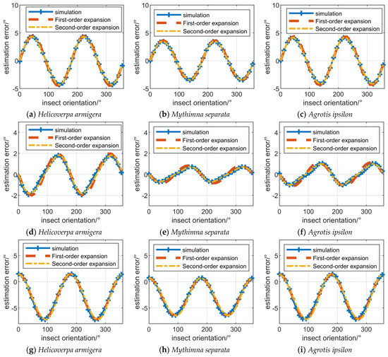

The and are zero in the first and second system, and and cause orientation estimation errors. Thus, the orientation estimation errors in Figure 1a–f vary in the form of with the orientation of the insect. The minimum estimation error for insect orientation is at 0, 90°, 180° and 270°. The and are 1 in the third system, and and cause orientation estimation errors. Thus, the orientation estimation errors in Figure 1g–i vary in the form of with the orientation of the insect. Due to the difference between and , the orientation estimation error is also affected by the constant error term, as presented in Equation (29). The and are not 1, and and are not 0 in the fourth system. Thus, the estimation errors of insect orientation vary approximately in the form of a regular trigonometric function with respect to insect orientation.
The orientation estimation error calculated by simulation of the fifth to eighth systems are illustrated in Figure 2. The orientation estimation error approaches 90° in some cases, indicating that insect orientation solution ambiguity errors occur, although the insect orientation solution ambiguity errors usually occur only in partial orientation intervals. It can be seen that compared with the first four systems, the polarization measurement errors of the fifth to eighth systems are more severe, which is the condition for the occurrence of ambiguity resolution errors.

Figure 2.
The influence of polarization measurement errors on solving the orientation ambiguity.
In order to analyze the influence of polarization measurement errors on orientation distribution, simulations are conducted on all insects in the dataset, and the SM in the Ku band are chosen. The SMs of insects with different orientations are obtained through Equation (14), and the orientations of insects are evenly distributed in the range of 0–360°, as presented in Figure 3.
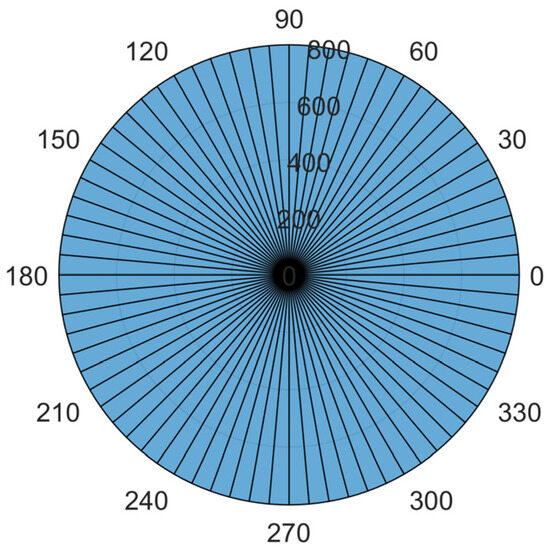
Figure 3.
Insect orientation distribution without the influence of polarization measurement errors.
The simulation results of insect orientation distribution are presented in Figure 4. In Figure 4a,b, the measured insect orientations cluster in the direction of H or V polarization. This is due to the fact that the orientation estimation error is smaller at insect orientations of 0, , and , whereas the more the insect’s orientation deviates from these angles, the greater the orientation estimation errors. It can be seen that and are the reasons that cause insects to converge towards the H and V polarization direction. In Figure 4c, the measured insect orientations cluster in direction, deviating from H and V polarization. This is due to the fact that for errors of the form, the larger insect orientation estimation errors occur at 0, , and . Superimposing the constant error term due to the difference between and , the final insect orientation will be biased towards the or . For the more general case, the insect orientation will be biased to or . These analyses are consistent with Equation (29). For cases with huge polarization measurement errors, as presented in Figure 4e–h, the insect orientation will be more clustered or deviated towards H and V polarization.
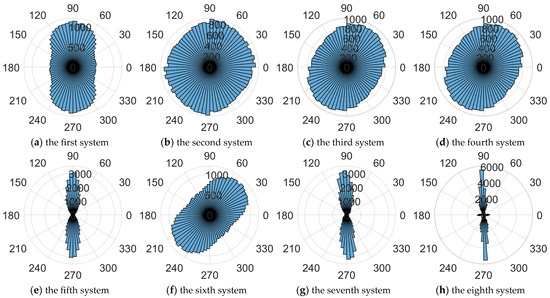
Figure 4.
The influence of polarization measurement errors on the distribution of insect orientation.
3.4. Analysis of Radar Measurement Data
In order to verify the effect of polarization measurement errors on the insect orientation estimation in the real system, the orientation distribution of the insect target is recorded based on a Ku band entomological radar and an X band entomological radar, as presented in Figure 5. The Ku band entomological radar has been introduced in [10] and [21]. The X band radar adopts the same waveform and operating mode as the Ku band radar, and system parameters of the X band entomological radar are presented in Table 2.
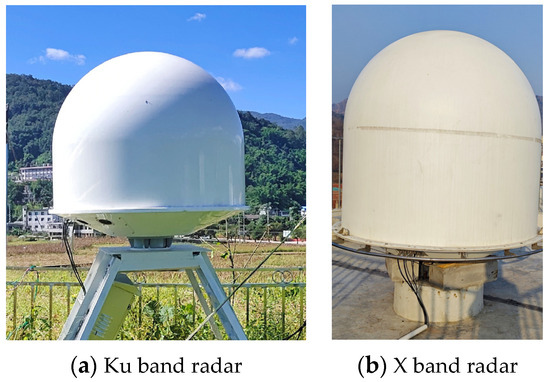
Figure 5.
The Ku band fully polarized entomological radar (a) and X band fully polarized entomological radar (b).

Table 2.
System parameters of the X band entomological radar.
The Ku band radar recorded the orientation of the measured targets in the air on the evening of 2 September 2020, during the time period from 17:00 to 23:00 Beijing time. The X band radar recorded the orientation of the measured targets in the air throughout the day of 13 October 2023. The SM of the measured targets has not been calibrated, and the orientation distributions of all targets are presented in Figure 6. In Figure 6, 0 represents the H polarization direction, 90° represents the V polarization direction.
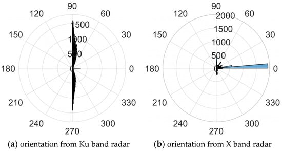
Figure 6.
The orientation distribution obtained from Ku band and X band radar.
It can be seen that the clustering degree of measured insect orientation is relatively high. For the Ku band radar, most of the measured orientation of the targets tend to cluster towards the V polarization direction, while a small portion of the measured orientations tend to cluster towards the H polarization direction. For the X band radar, most measured orientations of the target cluster towards the H polarization direction, while a small portion of the measured orientations cluster towards the V polarization direction or other directions. On the one hand, the convergence of insect orientation towards the H and V polarization directions indicates that and are the main polarization measurement errors affecting insect orientation calculation; Conversely, these distributions demonstrate the necessity of polarization calibration for accurately obtaining polarization information of the fully polarized radar.
4. The Influence of Polarization Measurement Errors on Mass and Body Length Measurement
System polarization measurement errors could lead to estimation errors in insect mass and body length, resulting in severe distortion of the measured insect mass and body length distribution. In the following, the insect mass and body length calculation methods are first introduced, and the influence of polarization measurement errors on the calculation of SM eigenvalues, which is closely related to estimators for insect mass and body length, are theoretically derived. Then, the influence of polarization measurement errors on individual insect mass and body length calculations and the statistical distribution of insect mass and body length are analyzed through simulation. Finally, the influence of polarization measurement errors on the insect mass and body length distribution is demonstrated through the measurement results of two fully polarized radars.
4.1. The Calculation Method of Insect Mass and Body Length
For the fully polarized entomological radar, different types of estimators can be calculated through target SMs, and the target mass or body length can be calculated using the constructed mapping from these estimators to the target mass or body length [9,14].
From Equations (13) and (14), it can be seen that and are the eigenvalues of . Most of the estimators could be calculated by and ; for example v, which is mostly used in the fully polarized entomological radar [15]:
The eigenvalues of could be expressed as
For some insects, corresponds to and corresponds to , while for other insects, corresponds to and corresponds to [20]. This is also the same for v, which might be calculated by one of or .
The mapping of insect mass and body length calculated by v could be expressed as:
where are the coefficients calculated through the Microwave Anechoic Chamber dataset. In the following, the influence of polarization measurement errors on v is analyzed, but the relevant conclusions could also be applied to other estimators.
4.2. Analysis on the Scattering Matrix Eigenvalues Calculation Error
The eigenvalues of could be expressed as
The first-order Taylor expansion of Equation (35) at , , , and G = 1 could be expressed as
By substituting Equations (19) and (35) into Equation (37) and simplifying them, we can obtain
where
It can be seen that is not only affected by , , and , but also by G. According to Equation (4), G is influenced by r and g, which are the target distance and the modulation of the antenna pattern on the echo intensity. The influence of r could be compensated by the measured target distance. And the influence of g could be compensated by the measured target angle and the antenna pattern for radar with monopulse measurement capability. However, for radars that do not use monopulse technology, the antenna pattern modulation might seriously affect g, thereby seriously affecting .
and bring error terms that vary in the form of with the orientation of the insect. and not only bring error terms that vary in the form of with the orientation of the insect, but also lead to a constant error term related to the difference between and .
Equation (38) could also be expressed as
where
The calculation error due to polarization measurement errors could be defined as
In order to verify the accuracy of Equation (42) about the calculation errors, simulations are also conducted on Helicoverpa armigera, Mythimna separata and Agrotis ipsilon, and the SMs in the Ku band are chosen. Through Equation (14), the SMs of insects with different orientations can be obtained. Then, the first, third, ninth and tenth group of polarization measurement errors in Table 1 are used to obtain radar-measured target SMs. The of these insects is calculated using Equation (31) through these measured target SMs, and the calculation errors are recorded.
Taylor’s first-order and second-order expansions are also used to obtain the calculation error of .
The calculation error are illustrated in Figure 7. It can be seen that the calculation error of insects calculated through first-order Taylor expansion and second-order Taylor expansion is relatively close to the calculation error obtained through simulation. This indicates that the estimation errors of calculated through Equation (42) obtained by first-order Taylor expansion is accurate enough to describe the calculation error.
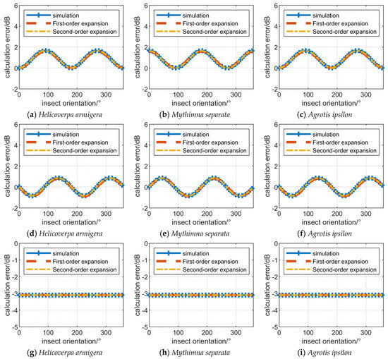

The calculation errors in Figure 7a–c are the sum of the form error and the constant error, and the calculation errors in Figure 7d–f vary in the form of , which is consistent with Equation (38). In the ninth system, only the modulation of the antenna pattern or G could influence the calculation of , and it could be seen that the calculation errors are a constant in Figure 7g–i. In addition, for cases where G is less than 1, will be smaller than . As will be seen in the following, G will also lead to smaller measurement results of insect mass and body length.
The , and G are not 1, and and are not 0 in the tenth system. Thus, in Figure 7j–l, the estimation error of varies approximately in the form of the sum of a regular trigonometric function and a constant error with respect to insect orientation.
The influence of polarization measurement errors on is similar to that on and is not described in detail in this paper.
4.3. Simulation on Individual Measurement Error and Insect Parameter Distribution Distortion
Equation (45) could also be expressed as
where log is an abbreviation of log10. For the case where v could be calculated from , the measured v could be expressed as
According to Equation (33), the measured mass of an insect could be expressed as
where is the mass estimation error of an insect:
Equation (49) presents the relationship between the insect mass estimation error and the calculation error. In subsequent simulations, it can be seen that the influence of polarization measurement errors on calculation is similar to that on insect mass estimation.
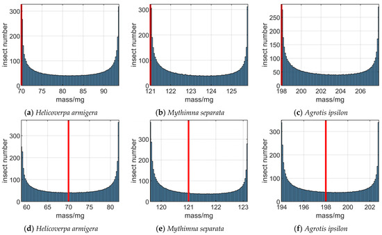
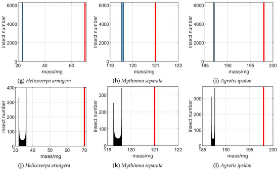
Simulations are conducted on Helicoverpa armigera, Mythimna separata and Agrotis ipsilon, and the SMs in the Ku band are chosen. The curve of the insect mass estimation error with insect orientation is illustrated in Figure 8. It could be seen from Figure 8a that the estimation error of insect mass varies approximately in the form of the sum of a function and a constant error with respect to insect orientation. And in Figure 8b, the estimation error of insect mass varies approximately in the form of . In Figure 8c, the measured mass is smaller than the actual mass, and the difference between the measured mass and the true mass is a constant. Figure 8d illustrates that the estimation error of insect mass varies approximately in the form of the sum of a regular trigonometric function and a constant error with respect to insect orientation, for the case where the influences of all polarization measurement errors are present.

In order to analyze the influence of polarization measurement errors on the mass distribution of insects, the mass of each insect in Figure 8 is also recorded, and the distribution of insects is presented in Figure 9. The real mass of insects is marked with a red line. It can be seen from Figure 9a–f that due to the varying influence of , , and on targets in different orientations, the calculated insect mass will diverge near the true mass. Figure 9g–i illustrate that G does not cause the distribution of insect mass to diverge but could lead to deviations in the measurement results of insect mass. Figure 9j–l illustrate that the influence of , , , and G on the mass distribution could overlap, leading to the divergence and decrease in insect mass measurement results from the true mass.
It is worth noting that in this paper, only the situation where the insect species are single and the orientation distribution is uniform is analyzed. In actual situations, the calculated insect mass distribution will be more complex.
Because the forms of calculating insect mass and body length are similar, the influence of polarization measurement errors on the mass are similar to that on the body length of insects and is not described in detail in this paper.
4.4. Analysis of Radar Measurement Data
The Ku and X band entomological radars introduced in Section 3 are used to measure insect mass, and data from the same time period are recorded. The SM of the measured targets has also not been calibrated, and the mass distributions of all targets are presented in Figure 10. Due to the fact that Ku band radar can only measure the mass of insects below 200 mg, Figure 10a only presents the distribution of insect mass below 200 mg. During the mass calculation process, the influence of r is compensated, but due to the lack of angle information of the target relative to the radar, the influence of g could not be compensated.
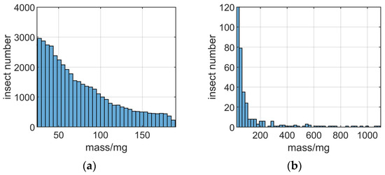
Figure 10.
The mass distribution obtained from Ku band and X band radar. (a) mass distribution from Ku band radar. (b) mass distribution from X band radar.
It can be seen from Figure 10 that the number of insects decreases with mass increases. In fact, for all statistical distribution results without compensating g, the number of larger insects (insect with mass larger than 100 mg) is always relatively small, which is seriously inconsistent with reality. According to the analysis above, only g could cause the measured mass of a large number of insects to be smaller. The flight trajectory of most measured insects does not pass through the center of the radar beam, which causes the measured mass of insects to be smaller than the real mass. Thus, the mass estimation error mainly depends on the flight trajectory and antenna pattern.
5. The Influence of Polarization Measurement Errors on the Characteristics of the Measured Scattering Matrix
The insect SMs measured by entomological radar often highly satisfy reciprocity and symmetry [17]. In this section, the polarization measurement errors are decomposed into the part that affects the reciprocity of the measured SM of the target and the part that affects the bilateral symmetry of the measured SM of the target. And the disruption of the reciprocity and symmetry of the insect’s measured SM caused by polarization measurement errors is demonstrated through a simple method. Then, through simulation and data from two fully polarized radars, the influence of polarization measurement errors on the reciprocity and bilateral symmetry of the target’s measured SM is analyzed.
5.1. The Influence of Polarization Measurement Errors on Reciprocity
The in Equation (12) could be decomposed into and .
And Equation (12) could be expressed as
Assuming , and , Equation (51) could be expressed as
where
According to [22,23], for the target that satisfy reciprocity, the off-diagonal elements of the SM are the same:
However, according to Equations (53) and (54), it can be seen that could affect the reciprocity of the measured target SM. When the off-diagonal elements of S are 0 or is 1, the could satisfy reciprocity. While in other cases, will no longer satisfy reciprocity.
The operator could be used to calculate the degree of target reciprocity [16,22]:
where is the target SM in the form of a 4 × 1 vector, and represents the 2-norm of the vector. The of the target ranges from 0 to , and the smaller the value, the higher the degree of reciprocity of the target. In the absence of polarization measurement errors, the degree of insect reciprocity does not vary with orientation.
In the case of , and , the degree of reciprocity of Helicoverpa armigera, Mythimna separata, and Agrotis ipsilon varying with orientation is illustrated in Figure 11a. It can be seen that the of target reciprocity varies with the orientation of the insect, and it is lowest at approximately 0, 90°, 180° and 270°, which means that the degree of reciprocity is the highest at these angles. This is because at these angles, the insect SM off-diagonal elements are close to 0, so the degree of target reciprocity is less affected by .

Figure 11.
The influence of polarization measurement errors to the characteristics of the measured SM. (a) Influence of to reciprocity. (b) Influence of to bilateral symmetry. (c) Influence of C to bilateral symmetry.
5.2. The Influence of Polarization Measurement Errors on Bilateral Symmetry
According to [18], for the targets that satisfy bilateral symmetry, the is real:
However, in the case of , or , might not be real.
Assuming , and , Equation (51) could be expressed as
And under the influence of , by substituting the matrix elements in Equation (58) into Equation (57), could be expressed as
According to Equations (57) and (59), it can be seen that when the off-diagonal elements of S are 0 or is 1, is real. While in other cases, will not remain real, and will no longer satisfy bilateral symmetry.
The operator D could be used to calculated the degree of target bilateral symmetry [16,22]:
where represents the inner product of and. Similar to , the of the target ranges from 0 to , and the smaller the value, the higher the degree of bilateral symmetry of the target. In the absence of polarization measurement errors, the degree of insect bilateral symmetry does not vary with orientation.
In the case of , and , the degree of bilateral symmetry of insects varying with orientation is illustrated in Figure 11b. It can be seen that the degree of target bilateral symmetry varies with the orientation of the insect, and it is highest at approximately 0, 90°, 180° and 270°. As introduced earlier, the insect SM off-diagonal elements are close to 0 at these angles, and the degree of target bilateral symmetry is not affected by when the off-diagonal elements of S are 0.
Assuming and Equation (51) could be expressed as
And under the influence of and , by substituting the matrix elements in Equation (61) into Equation (57), could be expressed as
According to Equation (62) and Equation (57), for cases other than , will not remain real, and will no longer satisfy bilateral symmetry.
In the case of , and , the degree of bilateral symmetry of insects varying with orientation is illustrated in Figure 11c. The degree of target bilateral symmetry varies with the orientation of the insect, indicating that and could also influence the degree of symmetry of the insect’s measured SM.
5.3. Analysis of Radar Measurement Data
The data measured by the Ku and X band entomological radars introduced in Section 3 are analyzed. The SM of targets has also not been calibrated, and the degree of reciprocity and bilateral symmetry of all targets are presented in Figure 12 and Figure 13. The mean, maximum, median and variance of the degree of reciprocity and the degree of bilateral symmetry measured by these two radars are presented in Table 1.

Figure 12.
The distribution of degree of reciprocity obtained from Ku band and X band radar. (a) insects measured by Ku band radar. (b) insects measured by X band radar.

Figure 13.
The distribution of degree of bilateral symmetry obtained from Ku band and X band radar. (a) insects measured by Ku band radar. (b) insects measured by X band radar.
According to the introduction of the reciprocity and symmetry of insect targets in the dataset in [20], the degree of reciprocity and symmetry of insect targets is high. Table 3 also presents the mean, maximum, median and variance of the degree of reciprocity and bilateral symmetry measured in the Microwave Anechoic Chamber. It can be seen that in the Ku and X bands, the degree of reciprocity and bilateral symmetry measured by radar is much lower than that measured in a Microwave Anechoic Chamber.

Table 3.
Comparison of scattering characteristics between insect SM dataset measured by Microwave Anechoic Chamber and target SMs measured by radars.
6. Discussion
Polarization measurement errors, including G, , , and , could lead to measurement errors in insect orientation, mass and body length, as well as disrupt the reciprocity and bilateral symmetry of the measured SM of insects. This paper first models the measurement process of the target SM, and then analyzes the influence of polarization measurement errors on the calculation of insect orientation, mass, body length and scattering characteristics of insects through theoretical derivation, simulation and measured data from entomological radars.
, , and lead to error terms in the measurement of insect orientation that vary in trigonometric form with insect orientation. and could also bring additional constant error terms. The method for calculating the insect orientation estimation error through polarization measurement errors is given in Equation (29). When calculating the orientation distribution of a large number of insects, and will lead the calculated insect orientation to cluster towards the H or V polarization direction, and and will lead the calculated insect orientation to deviate from the H or V polarization direction. The measured data from two fully polarized entomological radars indicate that most measured insect orientation cluster in the H or V polarization direction. Thus, and are the main factors affecting the measured insect orientation distribution in the actual system.
, , and lead to error terms in the measurement of insect mass and body length that vary in trigonometric form with insect orientation. G, and could bring additional constant error terms. The method for calculating the insect mass estimation error through polarization measurement errors is given in Equations (42) and (49), and the estimation error calculation method of body length are similar. When calculating the mass distribution of a large number of insects, , , and will mainly lead the mass and body length distribution of insects to diverge, and G will always lead to a smaller measured mass and measured body length of all the insects. The measured data from two fully polarized entomological radars indicate that G or the modulation of the antenna pattern are the main factors affecting the measured insect mass and body length distribution in the actual system. Thus, in the distribution of measured insect mass, the number of small-mass insects is always abnormally high, and the number of large-mass insects is abnormally low.
, which is the ratio of and , could disrupt the reciprocity of the measured SM, and , and could disrupt the bilateral symmetry of the measured SM. The comparison between insect data measured by Microwave Anechoic Chamber and entomological radar indicates that the reciprocity and bilateral symmetry of insect targets are significantly reduced due to the influence of polarization measurement errors.
Usually, using a large amount of simulation to calculate the influence of polarization measurement errors on insect parameter measurement consumes a lot of time. The calculation methods for orientation estimation error, mass estimation error and body length estimation error could be quickly used to calculate estimation errors and guide the design of the system.
In addition, there are two methods to solve the polarization measurement errors of the system and improve the accuracy of insect parameter measurement. Antenna pattern modulation is the main reason for the smaller measurement results of insect mass and body length, and by designing estimators that are not affected by echo intensity, insect mass and body length can be estimated to avoid the influence of antenna pattern modulation. Although the two eigenvalues of the measured SM , and are both affected by G in the same way, the ratio of and is not affected by G. Thus, the amplitude and phase of this ratio have great potential as estimators for calculating insect mass and body length without being affected by G.
Another method is to measure the polarization measurement errors of the system and compensate for the measured SM to obtain the accurate target SM, which is also known as polarization calibration. The traditional polarization calibration method calculates polarization measurement errors by measuring multiple known SM targets. However, entomological radars are often deployed in the wild for a long time, making it difficult to measure targets with known SM. According to the analysis in Section 5, could affect the reciprocity of the measured target SM, while , and could affect the bilateral symmetry of the measured target. It is possible to first collect a certain number of insect SMs, and then use , , and to compensate the influence of , , and to these measured SMs. The set of , , and that maximizes the degree of reciprocity and degree of symmetry of these SMs is the accurate estimate of , , and . The influence of , , and on target SMs could be obtained by compensating the measured SM with the estimates of , , and .
7. Conclusions
In this paper, the influence of polarization measurement errors on the estimation of insect orientation, mass and body length and the calculation of reciprocity degree and bilateral symmetry degree are introduced. Polarization measurement errors can cause estimation errors in insect orientation, mass and body length to fluctuate with insect orientation, ultimately leading to the measured insect orientation clustering in certain directions, the estimates of mass and body length decreasing and the distribution of the measured insect mass and body length diverging. Polarization measurement errors could also reduce the degree of reciprocity and symmetry of the target measured SM.
In addition, the calculation methods for the orientation, mass and body length estimation errors of known SMs of insects are given. Methods used to solve polarization measurement errors are briefly introduced. In the future, these methods will be studied to thoroughly address the influence of polarization measurement errors.
Author Contributions
M.L. developed the method and wrote the manuscript; M.L., T.Y. and F.Z. designed and carried out the data analysis; T.Y., R.W., C.W. and W.L. reviewed and edited the manuscript. All authors have read and agreed to the published version of the manuscript.
Funding
This research was funded by the Special Fund for Research on National Major Research Instruments under Grant 31727901; and The National Natural Science Foundation of China (Grant No. 62001021 and 62225104).
Data Availability Statement
The data presented in this study are available on request from the author. The data are not publicly available due to privacy restrictions.
Conflicts of Interest
The authors declare no conflicts of interest.
References
- Hu, G.; Lim, K.S.; Horvitz, N.; Clark, S.J.; Reynolds, D.R.; Sapir, N.; Chapman, J.W. Mass seasonal bioflows of high-flying insect migrants. Science 2016, 354, 1584–1587. [Google Scholar] [CrossRef] [PubMed]
- Holland, R.A.; Wikelski, M.; Wilcove, D.S. How and why do insects migrate? Science 2006, 313, 794–796. [Google Scholar] [CrossRef] [PubMed]
- Clarke, A. Energy flow in growth and production. Trends Ecol. Evol. 2019, 34, 502–509. [Google Scholar] [CrossRef] [PubMed]
- Yu, T.; Li, M.; Li, W.; Cai, J.; Wang, R.; Hu, C. Insect Migration Flux Estimation Based on Statistical Hypothesis for Entomological Radar. Remote Sens. 2022, 14, 2298. [Google Scholar] [CrossRef]
- Drake, V.A.; Hatty, S.; Symons, C.; Wang, H. Insect Monitoring Radar: Maximizing Performance and Utility. Remote Sens. 2020, 12, 596. [Google Scholar] [CrossRef]
- Drake, V.A.; Reynolds, D.R. Radar Entomology: Observing Insect Flight and Migration; CABI: Wallingford, UK, 2012. [Google Scholar]
- Wang, R.; Kou, X.; Cui, K.; Mao, H.; Wang, S.; Sun, Z.; Li, W.; Li, Y.; Hu, C. Insect-Equivalent Radar Cross-Section Model Based on Field Experimental Results of Body Length and Orientation Extraction. Remote Sens. 2022, 14, 508. [Google Scholar] [CrossRef]
- Drake, V. Insect-monitoring radar: A new source of information for migration research and operational pest forecasting. Pest Control. Sustain. Agric. 1993, 452–455. [Google Scholar]
- Chapman, J.; Smith, A.; Woiwod, I.; Reynolds, D.; Riley, J. Development of vertical-looking radar technology for monitoring insect migration. Comput. Electron. Agric. 2002, 35, 95–110. [Google Scholar] [CrossRef]
- Long, T.; Hu, C.; Wang, R.; Zhang, T.; Kong, S.; Li, W.; Cai, J.; Tian, W.; Zeng, T. Entomological radar overview: System and signal processing. IEEE Aerosp. Electron. Syst. Mag. 2020, 35, 20–32. [Google Scholar] [CrossRef]
- Li, C.; Li, Y.-Z.; Yang, Y.; Pang, C.; Wang, X.-S. Moving target’s scattering matrix estimation with a polarimetric radar. IEEE Trans. Geosci. Remote Sens. 2020, 58, 5540–5551. [Google Scholar] [CrossRef]
- Zhang, Z.; Shi, J.; Wen, F. Phase Compensation-based 2D-DOA Estimation for EMVS-MIMO Radar. IEEE Trans. Aerosp. Electron. Syst. 2023. [Google Scholar] [CrossRef]
- Hu, C.; Li, W.; Wang, R.; Liu, C.; Zhang, T. Accurate insect orientation extraction based on polarization scattering matrix estimation. IEEE Geosci. Remote Sens. Lett. 2017, 14, 1755–1759. [Google Scholar] [CrossRef]
- Wang, R.; Hu, C.; Liu, C.; Long, T.; Kong, S.; Lang, T.; Gould, P.J.; Lim, J.; Wu, K. Migratory insect multifrequency radar cross sections for morphological parameter estimation. IEEE Trans. Geosci. Remote Sens. 2018, 57, 3450–3461. [Google Scholar] [CrossRef]
- Hu, C.; Li, W.; Wang, R.; Long, T.; Liu, C.; Drake, V.A. Insect biological parameter estimation based on the invariant target parameters of the scattering matrix. IEEE Trans. Geosci. Remote Sens. 2019, 57, 6212–6225. [Google Scholar] [CrossRef]
- Li, W.; Hu, C.; Wang, R.; Kong, S.; Zhang, F. Comprehensive analysis of polarimetric radar cross-section parameters for insect body width and length estimation. Sci. China Inf. Sci. 2021, 64, 122302. [Google Scholar] [CrossRef]
- Hu, C.; Li, M.; Li, W.; Wang, R.; Yu, T. A data-driven polarimetric calibration method for entomological radar. IEEE Trans. Geosci. Remote Sens. 2022, 60, 5114014. [Google Scholar] [CrossRef]
- Li, M.; Wang, R.; Li, W.; Zhang, F.; Wang, J.; Hu, C.; Li, Y. Robust Insect Mass Estimation with Co-polarization Estimators for Entomological Radar. IEEE Trans. Geosci. Remote Sens. 2023, 61, 5106714. [Google Scholar] [CrossRef]
- Sarabandi, K.; Ulaby, F.T. A convenient technique for polarimetric calibration of single-antenna radar systems. IEEE Trans. Geosci. Remote Sens. 1990, 28, 1022–1033. [Google Scholar] [CrossRef]
- Hu, C.; Li, W.; Wang, R.; Long, T.; Drake, V.A. Discrimination of parallel and perpendicular insects based on relative phase of scattering matrix eigenvalues. IEEE Trans. Geosci. Remote Sens. 2020, 58, 3927–3940. [Google Scholar] [CrossRef]
- Hu, C.; Li, W.; Wang, R.; Li, Y.; Li, W.; Zhang, T. Insect flight speed estimation analysis based on a full-polarization radar. Sci. China Inf. Sci. 2018, 61, 109306. [Google Scholar] [CrossRef]
- Touzi, R.; Shimada, M.; Motohka, T. Calibration and Validation of Polarimetric ALOS2-PALSAR2. Remote Sens. 2022, 14, 2452. [Google Scholar] [CrossRef]
- Cameron, W.L.; Leung, L.K. Feature motivated polarization scattering matrix decomposition. In Proceedings of the IEEE International Conference on Radar, Cambridge, MA, USA, 7–10 May 1990; pp. 549–557. [Google Scholar]
Disclaimer/Publisher’s Note: The statements, opinions and data contained in all publications are solely those of the individual author(s) and contributor(s) and not of MDPI and/or the editor(s). MDPI and/or the editor(s) disclaim responsibility for any injury to people or property resulting from any ideas, methods, instructions or products referred to in the content. |
© 2024 by the authors. Licensee MDPI, Basel, Switzerland. This article is an open access article distributed under the terms and conditions of the Creative Commons Attribution (CC BY) license (https://creativecommons.org/licenses/by/4.0/).