Abstract
To generate an orthophoto mosaic from a collection of aerial images, the original images are first orthorectified individually using a Digital Surface Model (DSM). Then, they are stitched together along some determined seamlines to form the orthophoto mosaic. Determining appropriate seamlines is a critical process, as it affects the visual and geometric quality of the results. The stitching process can usually be done in frame-to-frame or multi-frame modes. Although the latter is more efficient, both still involve a lot of pre-processing, such as creating individual orthophotos, image registration, and overlap extraction. This paper presents a novel coarse-to-fine approach that directly determines the seamline network without such pre-processing. Our method has been specifically applied for UAV photogrammetry projects where, due to the large number of images and the corresponding overlaps, the orthophoto mosaic generation can be very challenging and time-consuming. We established the seamlines simultaneously for all the images through a two-step process. First, a DSM was generated, and a low-resolution grid was overlayed. Then, for each grid point, an optimal image was selected. Then, the grid cells are grouped into polygons based on their corresponding optimal image. Boundaries of these polygons established our seamline network. Thereafter, to generate the orthophoto mosaic, we overlayed a higher/full resolution grid on the top of the DSM, the optimal image of each point of which was quickly identified via our low-resolution polygons. In this approach, not only seamlines were automatically generated, but also were the need for the creation, registration, and overlap extraction of individual orthophotos. Our method was systematically compared with a conventional frame-to-frame (CF) technique from different aspects, including the number of double-mapped areas, discontinuities across the seamlines network, and the amount of processing time. The outcomes revealed a 46% decrease in orthophoto generation time and a notable reduction in the number of double-mapped areas, sawtooth effects, and object discontinuities within the constructed orthophoto mosaic.
1. Introduction
The generation of orthophoto mosaics using drone images is an important application that has attracted a lot of interest in recent years [1,2,3,4,5,6,7]. To create an orthophoto mosaic from a set of images, individual orthophotos are initially produced through orthorectification using direct or indirect methods [8,9,10]. Then, they are registered, and the overlap areas between the neighboring orthophotos are determined [11]. Next, the border lines (so-called seamlines network) at which the individual orthophotos need to be cut and stitched together are detected [12]. The network of seamlines, which is crucial for ensuring the visual and geometric quality of the orthophoto mosaic, needs to be accurately defined using frame-to-frame or multi-frame methods [13,14]. These seamlines guide the stitching of individual orthophotos, culminating in the creation of the final, seamless orthophoto mosaic [15]. However, there are challenges and complications at every step of mosaic generation, particularly in drone datasets.
In most cases, a drone image covers only a small area on the ground. Therefore, thousands or even tens of thousands of images are needed to create the orthophoto of a large area. This means that although we need only a small portion of each image, the complete formation of the orthophoto mosaic requires all of them to be orthorectified [12]. As shown in Figure 1, only a small part of the individual orthophotos 1, 2, 3, 4, 10, 11, 12, and 13 are used to create the orthophoto of the red rectangle. However, all related individual orthophotos should be registered with respect to each other, and seamlines in overlapping areas of individual orthophotos should be determined. As a result, the orthophoto mosaic generation can become time-consuming in processing the data, especially when the number of images is large [16].
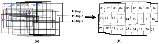
Figure 1.
Orthophoto mosaic generation using drone images with high forward and lateral overlaps in three flight lines: (a) overlapped orthorectified drone images, (b) orthophoto mosaic (the seamline network denoted by the black curve lines).
At the image registration stage, there is a further challenge. Image registration mainly involves key point extraction, image matching, and solving image-to-image transformations [17]. Image matching methods can include matching errors which affect the continuity of the resulting orthophoto mosaic where individual orthophotos are stitched together [18]. Many studies have been conducted to analyze and compare the performance of image-matching algorithms for image-stitching tasks [19].
Moreover, seamline detection in the image space is another challenging task. Although detecting seamlines is automatic, it often requires post-processing to improve the results. This is because the difference in the perspectives of the images is high at high-rise objects like buildings, trees, cars, and extruded roads and can lead to clear discontinuities in the resulting orthophoto mosaic [20]. This issue is particularly evident with drone imagery since the images are captured from close proximity to the ground. To avoid this problem, seamlines undergo an optimization process to find the best seamlines that pass over the minimum number of high-rise objects possible [21]. To optimize the seamlines, the existing optimization methods can be grouped into frame-to-frame (local) [22,23,24] and multi-frame (global) [25,26,27]. Frame-to-frame methods determine the optimized seamlines image by image, whereas in the multi-frame approaches this is done simultaneously. In both approaches, the main intention is to reduce the processing time and/or the number of high-rise objects passing through the seamlines.
For example, aiming to reduce the computation time, ref. [12] introduced a stitching method for generating orthophoto mosaics from UAV images. Initially, individual ortho images are generated, followed by the creation of initial seamlines using Voronoi diagrams. Subsequently, the watershed segmentation algorithm is applied to the individual orthophotos, and the resulting edges are utilized to optimize seamlines, avoiding buildings. While processing time was reduced compared to Dijkstra’s method, more buildings intersected with the seamlines. As another example [22], they applied their method to two pairs of individual UAV orthophotos. Initially, seamlines were generated in overlapping areas using the Voronoi diagram. Auxiliary data from the DSM helped identify buildings and optimize the initial seamlines. This approach reduced processing time and the number of buildings intersecting with seamlines compared to the Dijkstra’s method. Additionally, a stitching-based method was developed to generate a UAV orthophoto mosaic [16], using both image information and ground data. The result was fewer buildings intersecting with the seamlines compared to OrthoVista 5.6.3 software. They recommended exploring a multi-scale strategy for improved processing efficiency. Furthermore, ref. [28] introduced a super pixel approach to improve calculation time efficiency. They extracted overlapping areas from adjacent orthophotos and determined seamlines using the Dijkstra method. Seamline optimization occurred in low-resolution image space before being refined in the original image space, resulting in reduced processing time compared to their pixel-based method. However, the method proved to be slower compared to directly applying the Dijkstra method.
As can be seen, creating a method for generating orthophoto mosaics through image stitching requires several common steps. These include generating individual orthophotos, accurately registering them, and detecting and optimizing seamlines on the orthophotos. However, the process can be time-consuming [16], especially with drone images covering small ground areas. It can also result in discontinuities at the borders of adjacent orthophotos [22]. Two main reasons account for these discontinuities. Firstly, errors in the image matching method may lead to inaccuracies in tie point matching, causing boundary jumps between neighboring orthophotos. Secondly, seamlines may cross high-rise objects, especially buildings, due to differences in perspective between neighboring images.
We introduced a novel approach [29] that suggested a global DSM-based mosaic generation to increase the speed and reduce the number of discontinuities. Instead of creating individual orthophotos, this method involves generating a comprehensive orthophoto of the entire area using DSM cells. Each DSM cell was projected onto one of the visible images, and the pixel intensity from the corresponding image filled the orthophoto mosaic pixel of that DSM cell. Compared to the existing methods, this approach eliminated the need for matching, image registration, and overlap extraction. This leads to a reduction in discontinuities and the processing time. However, processing all DSM cells still requires a considerable amount of time. Therefore, in this paper, we propose a new method to enhance processing speed without sacrificing orthophoto continuity. We initially employ a low-resolution DSM grid, for each cell of which we identify the closest image (referred to as the optimal image). Subsequently, the grid cells are organized into polygons based on the corresponding optimal images, defining our seamline network. To generate the orthophoto mosaic, we overlay a higher/full-resolution grid onto the DSM, swiftly identifying the optimal image for each orthophoto mosaic pixel using the seamline polygons. Compared to our previous work, we expect this approach to reduce processing time even more compared to the existing ones. In the meantime, similar to [29], it eliminates the need for orthorectification, registration, or overlaps the area extraction of individual orthophotos. Furthermore, due to its pixel-by-pixel formation, we anticipate reduced discontinuities in the orthophoto mosaic.
Overall, the main contributions of this study are: (a) The development of a fast and automatic seamline generation technique within the DSM space. (b) Constructing the large-scale orthophoto mosaic with no need for the generation of individual orthophotos, nor their registration and overlap areas extraction and the rest of this paper is organized as follows. Section 2 reviews the works related to seamline detection methods. In Section 3, details of our method are given. We show how seamlines are automatically generated in the object space and how the final orthophoto mosaic is constructed without needing individual orthophoto creation. Section 4 evaluates the algorithm and compares the results with those obtained using a common image mosaicking method. Finally, this paper concludes the study with a conclusion in Section 5.
2. Related Work
Two types of orthophoto mosaic generation approaches are usually employed to construct an orthophoto mosaic of a set of drone images: frame-to-frame and multi-frame (or so-called local and global). The general workflow of a typical frame-to-frame approach [30] is shown in Figure 2. As can be seen, the orthophotos of the first and second pairs of images are generated. The resulting orthophotos are then registered (a), and the overlap between them is identified (b). Next, the features within this overlap are searched in order to identify the most appropriate pixels for stitching the orthophotos (c). These pixels together establish a seamline segment at which the two orthophotos are stitched (d). As shown in Figure 2, the process is repeated to join the subsequent orthophotos until the complete orthophoto mosaic is constructed. In contrast to the frame-to-frame methods, the multi-frame methods register all individual orthophotos and identify the seamlines in a single phase. These methods, mostly presented in recent years, are more time-efficient than the frame-to-frame methods as they eliminate some of the intermediate steps [27].
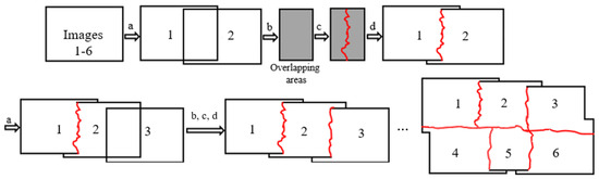
Figure 2.
Orthophoto mosaic generation of six images 1–6 using a common frame-to-frame approach. (a) Image registration, (b) overlapping area extraction, (c) seamline detection, and (d) image stitching. The seamlines are denoted by the red lines.
As can be seen, the creation of orthophoto mosaics through image stitching, whether employing frame-to-frame or multi-frame methods, involves distinct yet interrelated steps. These steps include producing individual orthophotos, registering them, extracting overlapping areas, identifying seamlines, and ultimately integrating them into a complete orthophoto mosaic. When working with UAV imagery, which typically captures only a small ground area, creating an orthophoto mosaic of a large area demands thousands, if not tens of thousands, of images. Thus, employing existing methods can give rise to the following challenges:
- Pre-processing overhead: both frame-to-frame and multi-frame methods require extensive pre-processing. This consumes substantial time and computational resources, particularly in large-scale drone mapping projects.
- Matching errors and discontinuities: Image stitching processes can suffer from matching errors, leading to inaccuracies in orientation parameters and alignment of neighboring orthophotos. This results in noticeable discontinuities near seamlines, especially around complex features like buildings and roads.
- Viewing angle disparities: variations in viewing angles among UAV-captured images contribute to visible discontinuities along seamlines, particularly around high-rise objects. Detecting and optimizing seamlines to minimize disruptions is challenging and time-consuming, especially in drone-based projects.
The challenges mentioned are considerably amplified compared to scenarios involving aerial imagery. In the following, the literature relating to the above challenges is briefly discussed.
2.1. Pre-Processing Overhead
Unfortunately, it is not easy to compare and assess related works in terms of processing time. This is due to the fact that each study only looked at a certain step in the production of orthophoto mosaic. For example, some studies concentrated on the generation of individual orthophotos [31,32]. Some researchers looked at image registration methods [18,33]. Some just generated and optimized seamlines [24,28]. Furthermore, the datasets used are different in terms of the number of images, orthophoto resolution, Ground Sampling Distance (GSD), processing system specifications, software, and so on. Nevertheless, time savings are addressed at all stages of orthophoto generating. For example, reference [16] highlighted the significant amount of time required to construct seamlines in UAV data and recommended a multiscale or top-down pyramid method for future study. Another example [22] demonstrated significantly reduced processing times for seamline detection compared to Dijkstra’s algorithm. By leveraging DSM, certain pixels are excluded from calculations, increasing speed. Meanwhile, some studies, such as [12], proposed a multi-frame strategy, rather than frame-to-frame, to enhance algorithm efficiency during the seamline determination step. In addition, ref. [28] proposed a super pixel technique to increase processing time efficiency. Compared to their pixel-based approach, the processing time decreased by the use of seamline optimization in low-resolution image space before being improved in the original space.
2.2. Matching Errors and Discontinuities
Another important challenge is the discontinuity/differences of features near the seamlines, resulting from matching errors. Image matching errors lead to inaccurate estimation of orientation parameters, which subsequently results in inaccurate alignment of neighboring orthophotos. Image matching can be performed based on feature extraction methods like Oriented FAST and Rotated BRIEF (ORB), Scale-Invariant Feature Transform (SIFT), Speeded Up Robust Features (SURF), KAZE, Accelerated-KAZE (A-KAZE), and BRISK (Binary Robust Invariant Scalable Keypoints) [33,34]. The effectiveness of feature extraction algorithms for image-stitching tasks is the subject of numerous studies. Researchers have attempted to improve the image-matching accuracy to generate a mosaic with higher precision [11,18,19,21]. For example, after registering two neighboring orthophotos, ref. [21] utilized the NCC criterion to measure the similarity degree between matched tie points in overlapping areas. Subsequently, matched points were filtered based on normalized cross correlation (NCC), where a value closer to zero indicates a lower mismatching error. The mosaic results demonstrate reduced discontinuity in the produced mosaic. To reduce the computation time, ref. [19] applied feature extraction methods like FAST and SIFT to image blocks instead of individual pixels, reducing computation time and discontinuity in the produced mosaics. Ref. [18] employed the Random Sample Consensus (RANSAC) method to delete generated SIFT blunder points in order to improve image registration accuracy and create a seamless mosaic. Also, ref. [11] introduced a two-step method for registering UAV images. Initially, two adjacent images are registered using the SURF method. Subsequently, after extracting the overlapping areas, optimized seamlines are determined. The left image is re-registered to the overlapping areas, followed by repeating the image stitching based on new orientation parameters. This method effectively reduces errors in UAV image registration.
2.3. Viewing Angle Disparities
Typically, each image possesses its unique viewing angle, leading to noticeable discontinuities along the sides of seamlines, particularly evident when passing over buildings, extruded roads, and moving objects [35,36]. To address this problem, researchers have tried to detect optimized seamlines so they do not cross over such objects. For example, ref. [25] registered single orthophotos and established initial seamlines using the multi-frame method employed the Area Voronoi Diagrams algorithm. Subsequently, they optimized the initial seamlines using radiometric information, resulting in a 37% reduction in processing time compared to the frame-to-frame method. Later, ref. [26] highlighted significant discontinuities along seamlines when passing through buildings and roads. Consequently, optimizing seamlines to avoid intersecting buildings and roads became imperative. They introduced a multi-frame method to optimize seamlines, reducing computing time. Their approach involved optimizing the nodes of the seamlines generated by the Voronoi Diagrams algorithm, aiming to minimize intensity differences along the seamlines. Accordingly, ref. [37] employed the traditional frame-to-frame method for mosaicking images, where the images are stitched consecutively, one after another. They have used a DSM to direct a seamline to avoid passing through the buildings. In another study, ref. [27] proposed a semi-automated multi-frame method for guiding seamlines using human–computer interaction. They recommended exploring multi-resolution or super pixel strategies to decrease computational time for future research. Moreover, ref. [38] optimized a frame-to-frame strategy for stitching individual orthoimages. Seamlines are optimized using a combination of marker-based watershed segmentation and Dijkstra’s algorithm. Ref. [23] developed a traditional frame-to-frame algorithm to mosaic UAV images. They used the edge detection method to limit the seamline along the roadways. Ref. [12] suggested a stitching-based method for generating orthophoto mosaics from UAV data. Individual orthophotos are initially produced, followed by initial seamlines generated using the Voronoi diagram technique. Watershed segmentation is then applied to each orthophoto, and the resulting edges are utilized to optimize seamlines while avoiding buildings. Furthermore, ref. [39] employed a histogram equalization strategy to prevent optimal seamlines from crossing over moving objects like cars. Another example [22] applied their mosaic generation approach to two pairs of UAV orthophotos. The Voronoi diagram are employed to create initial seamlines in overlapping regions. DSM helped locate buildings and detect optimized seamlines. In addition, ref. [16], a common orthophoto mosaic generation method, employed extra information from DSM to direct the seamlines so that they do not pass through the buildings. They employed both aerial and drone-based orthophotos to test their method, and recommended using large-scale pixels or a multi-scale strategy to reduce processing time. A traditional frame-to-frame seamline optimization method is proposed by [24]. The seamlines are optimized to pass over fewer buildings and follow the roads. Compared to Ortho Vista software (INPHO, 2005), processing time increased; however, compared to Dijkstra’s algorithm, processing time decreased.
To address the above problems, and to enhance the efficiency of existing methods, in previous research [29], we developed a global method that generates the orthophoto mosaic pixel by pixel. Our method did not rely on image stitching; as such, the matching errors that cause discontinuity issues were kept to a minimum. Furthermore, when seamlines cross over buildings and extruded roads, the discontinuity was minimal since the orthophoto pixels were filled using the best images having the least amount of relief displacement. Although this led to greater continuity in the resulting orthophoto, a substantial number of pixels still need to be processed. Thus, in this study, we provide a novel way to improve the efficiency method developed by [29], while maintaining its benefits. Our approach determines the optimal images at a low-resolution scale, and the seamlines are determined based on the grouped optimal images. Then, the production of orthophoto mosaics at full scale is conducted. As shown later, like our previous method, the results contain fewer double-mapping discontinuity effects. In addition, as no individual orthophotos need to be generated, the image registration and overlap area extraction steps are removed from the process. Thus, the process is more efficient, especially when the number of drone images is large.
3. Method
In this section, the method proposed in this paper is described. Instead of creating individual orthophotos, our method generates the complete orthophoto mosaic covering an entire region, using the DSM of the whole area. Each DSM cell is back-projected onto one of the images (reference image) where it is visible. Subsequently, the pixel intensity from the corresponding image fills the orthophoto mosaic pixel of that DSM cell. Figure 3 illustrates key components of the proposed algorithm, primarily tailored for drone imagery. Our algorithm comprises three core modules: initial processing, low-resolution grid-based seamline detection, and full-resolution orthophoto mosaic generation.
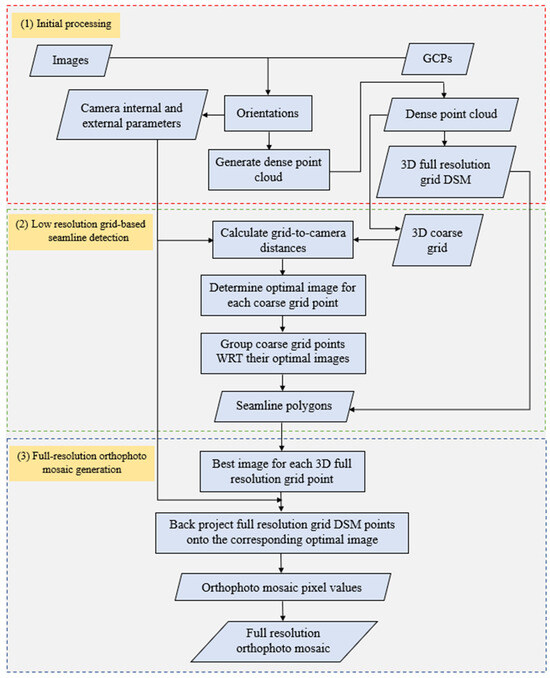
Figure 3.
An overview of the proposed method for detecting the seamline network generates a large-scale orthophoto mosaic.
The initial processing stage commences with the input of drone images and their corresponding ground control points, initiating orientation procedures. This phase yields essential internal and external orientation parameters alongside a sparse point cloud, subsequently refined into a dense point cloud and a Digital Surface Model (DSM).
Subsequently, a coarse network of seamlines is established to expedite the determination of reference images for each point in the full-resolution orthophoto mosaic. This is achieved by generating a 3D grid with significantly spaced intervals (10–20 times the original DSM interval) whose points are interpolated from the dense cloud computed earlier. An optimization procedure assigns a reference image to each grid point, and these coarse grid points are clustered to define seamlines based on their associated reference images. The resulting polygon boundaries delineate our seamline network.
Given that the resolution of the orthophoto mosaic matches that of the DSM, the pixels within it can seamlessly inherit values from their respective reference images. Retrieving these reference images for each full-resolution DSM cell is facilitated through a straightforward point-in-polygon method. Here, the polygons are the ones established based on the low-resolution grid, streamlining the process of associating reference images with specific areas of the DSM. In the following, the above steps are discussed in detail.
3.1. Initial Processing
To generate a full orthophoto mosaic, we need the camera orientation parameters, a full-resolution dense cloud, and DSM for the area of interest. This data is all produced at the initial processing stage, using photogrammetric software (in our study, Pix4DMapper 4.5.6). Given the UAV images and the corresponding ground control points, the images are first oriented. The results are the camera orientation parameters and a sparse point cloud, which includes the 3D coordinates of the tie points, from which the full-resolution dense cloud is created. The dense point cloud is then used to construct a DSM with a resolution equal to that of the orthophoto mosaic; thus, points on the final orthophoto mosaic have a one-to-one relation with the DSM cells. Alternatively, the location of its points can be interpolated from the underlying DSM.
3.2. Low-Resolution Grid-Based Seamline Detection
Our seamline detection algorithm is a two-step coarse-to-fine process in which the seamlines are delineated in the object space. As explained above, despite the traditional techniques that work by stitching individual orthophotos, we generate the orthophoto mosaic of the whole area on a pixel-by-pixel basis. For each pixel, we identify a reference (optimal) image which is used to define its value on the final mosaic. This means that when the number of images is large, identifying the reference images of all the mosaic pixels can become a lengthy process. Thus, in this paper, we do the job in two steps. At first, we generate a low-resolution grid, called a coarse grid (in this paper with a 30 cm interval) in the object space. Then, we only identify the reference images of points on this grid. This will greatly increase the speed of reference image selection when pixels of the complete orthophoto mosaic are being processed.
There are several ways to select the reference images which are mostly used for occlusion removal [32,40,41,42,43,44,45,46]. Examples are the image viewing angle [32,47], the distances from the occluded pixel [42], and the distance from the principal or nadir points of the nearby images [48]. In our work, we use a similar approach to determine the optimal images, with the grid-to-camera distance as the deciding factor [49]. The process is simple and fast, and is performed for all grid points of the low-resolution DSM. We developed the below pseudo code (Algorithm 1) for optimal image determination using the grid-to-camera (projection center (PC)) distance principle.
Using (TX, TY, TZ), the distances between each grid point and the relevant cameras/projection centers are calculated. The image with the shortest distance to the grid point is considered as its corresponding optimal image. Figure 4 shows an example. As can be seen, to find the optimal image for point P, the distances between the point and projection centers of all six cameras are measured (D1–D6). As can be seen, the camera PC5 (green color) has the smallest value (D5) and is, thus, selected as the optimal image. The process is repeated for all points of the low-resolution grid.
| Algorithm 1: Optimal image determination |
| Inputs: |
| (a) CGP = (CGPi) 3d Coarse Grid Points (Xi, Yi, Zi) |
| (b) DI = (DIj) Drone Images |
| (c) EO External Orientations parameters (TX, TY, TZ) |
| Output: OI = OIi Optimal Images |
| for CGPi ϵ CGP do |
| for DIj ϵ DI do |
| Cij = compute distance to the projection center ((Xi, Yi, Zi), EOj,) |
| End |
| OIi = DIj (Cij == min) |
| End |
| Return OI |

Figure 4.
Optimal image determination using the criterion of grid-to-camera distance.
Secondly, coarse DSM points are grouped based on their optimal image to detect seamlines network. Each optimal image is assigned a color. The result is a colored mosaic image (Figure 5), on which pixels with the same color refer to the same optimal image. At this stage, the 3D coarse grid points can be grouped into polygons based on their optimal images. In such a way that the points with the same optimal image (same color) are placed in the same group. The boundaries of the resulting polygons will form our seamline network, which is required to form the overall orthophoto mosaic. However, despite the most currently available techniques, they are determined directly in the object space, i.e., the low-resolution DSM. We used this set of polygons to generate the full-resolution orthophoto mosaic, as described in the following sub-section.
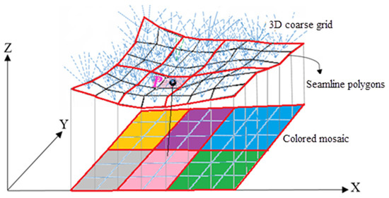
Figure 5.
Detection of seamline network on a 3D coarse grid. Each color represents an image, and the red lines are seamline polygons.
3.3. Full-Resolution Orthophoto Mosaic Generation
As mentioned before, currently available techniques work by stitching single orthophotos to generate a complete orthophoto mosaic. However, in our technique, we create the orthophoto of the whole area in one go, using the points of the full-resolution DSM. This approach can result in smoother and more seamless results than those created using traditional techniques. We use the low-resolution seamlines formed in the previous step to determine the optimal image corresponding to any point on the full-resolution DSM.
Figure 6 illustrates the overall view of our orthophoto mosaic generation method, which is performed pixel-by-pixel.
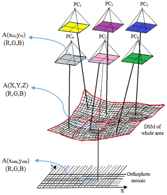
Figure 6.
Generation of orthophoto mosaics using the detected seamline polygons. Each color represents a detected optimal image.
Consider point A with (X, Y, Z)T coordinates as a sample. The first step is to define its corresponding DSM point. This is trivial, as the relation between the DSM and orthophoto mosaic points is one-to-one. Therefore, the main goal now is to define the pixel value of A, which should be derived from its corresponding optimal image. This is where our low-resolution seamlines/polygons are used. With a simple in-polygon check, the optimal image is quickly identified. Then, we back-project the point onto its image to extract its pixel value.
As we know, T is a three-dimensional point in the object space whose coordinates () in each of the camera coordinate systems is given by:
where R = Rω, Rφ, Rκ and T = (Tx, Ty, Tz) are external orientation parameters in the world coordinate system.
Set:
Using the following formula, we can then identify the image coordinates of the point corresponding to A:
where (f, cx, cy) are the internal camera parameters in pixel coordinates, xhd and yhd are the corresponding x and y distortion models estimated by:
K1, K2, K3, and P1, P2 are the radial and the tangential distortion coefficients, respectively.
The RGB values of the pixel at (xoi, yoi) are utilized to fill the orthophoto mosaic pixel of point A (xom, yom). The above process is repeated for all 3D full-resolution DSM points until the large-scale complete orthophoto mosaic of the entire area is generated. In the following, the tests carried out to evaluate the effectiveness of the proposed method are discussed.
4. Datasets and Experiments
4.1. Datasets
Two drone datasets were used in this experiment. The first dataset (Figure 7a) was obtained in an area near Qazvin city in Iran, and included a low-level hilly terrain covered with light grass. The second dataset (Figure 7b) corresponds to Golgir, a small city in southern Iran, a relatively flat area with various objects like buildings, roads, and some vegetation. Table 1 shows further details about the datasets.
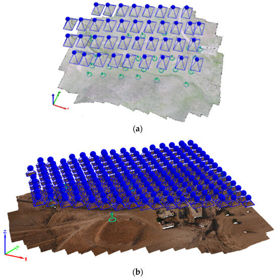
Figure 7.
Datasets used in our evaluations. (a) Low-level hilly terrain (Qazvin city). (b) Flat area (Golgir city).

Table 1.
Datasets used for evaluations.
We used MATLAB R2020b “https://www.mathworks.com (accessed on 20 February 2024)” for the implementations and Pix4Dmapper v 4.5.6 photogrammetric software “https://www.pix4d.com (accessed on 20 February 2024)” for the initial computations. All experiments were performed on a computer running a 64-bit Windows 10 operating system, with an Intel(R) Core (TM) i9-9900K CPU at 3.60 GHz, 32GB RAM, 1TB SSD, and 8TB hard drive.
4.2. Experimental Results and Discussion
This section describes the tests carried out to evaluate our method’s effectiveness and compares it with other common techniques. We evaluated our method by studying the double-mapped areas, the discontinuities along the seamlines, and the processing times. Our results are compared with those obtained with our previous work [29]. In addition, our work is compared with a traditional frame-to-frame method [30], which was well-documented and was not difficult to implement. As part of the frame-to-frame method, we had to use a matching algorithm and a mismatch removal technique. In this study, we used SURF for image matching and the RANSAC algorithm to eliminate and optimize mismatching. For both parts, we used the techniques developed by [17]. The large-scale orthophoto mosaic from dataset 1 and dataset 2, generated by our algorithm, is shown on the left side of Figure 8 and Figure 9, respectively. The corresponding seamline networks (the colored mosaic/polygons shown on the right sides of Figure 8 and Figure 9) are also overlayed on the mosaics (the red/yellow dotted lines). In both datasets, all the images are used to create the orthophoto mosaics. To generate seamlines, as mentioned in Section 3.2, an optimal image is first determined for each point of the low-resolution grid. The dimensions of a low-resolution grid are 10 times the original DSM interval (in our experiments 30 cm). Each optimal image is assigned a color. The grid points are grouped based on the optimal image so that the points that have the same optimal image (same color) are placed in the same group. The boundaries of the different groups define the seamlines on the DSM.
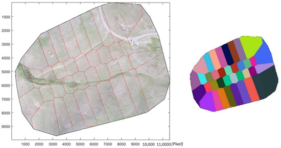
Figure 8.
Results of dataset 1: Orthophoto mosaic (left) and its colored mosaic (right) generated using the proposed method. The red dashed-lines overlay the seamline network.
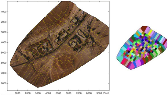
Figure 9.
Results of dataset 2: Orthophoto mosaic (left) and its colored mosaic (right) generated using the proposed method. The yellow dashed-lines overlay the seamline network.
In the following section, the tests carried out are described.
4.2.1. Double-Mapped Areas
When generating an orthophoto using a DSM, there would be an occluded area close to the objects with sudden relief change [50,51]. As illustrated in Figure 10, this causes an unpleasant doubling of RGB values in orthorectified images (Point C) [52]. The size of the occluded area grows when point C is reprojected with the second image (PC2), which is farther away. That means the occluded area can be larger for a DSM point that is farther from the camera. Researchers have offered many approaches for automatically detecting and removing occlusions [31], which are not covered in this study. Nevertheless, we expect our proposed method to result in less occluded areas, using the closest camera to any point to the intensity value of the relevant orthophoto mosaic pixel.
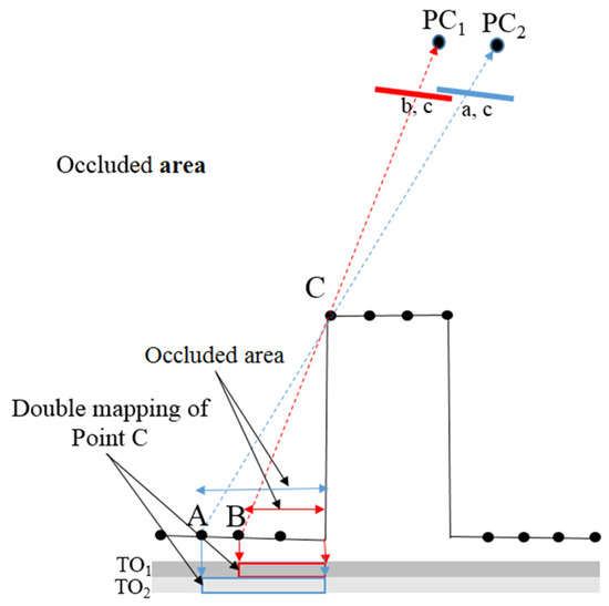
Figure 10.
The effect of optimal image determination on reducing double-mapped areas when generating orthophoto.
As dataset 1 did not include significant elevation changes, it did not have many occlusions to study in this experiment. So, we concentrated on the second dataset for evaluating the number of double-mapped areas. In the second dataset, there were many areas where the double mapping effect appeared. Some examples are shown in Figure 11, where we compare the results obtained by our method with the frame-to-frame technique (CF). As can be seen in Figure 11b and d, the double-mapped areas in orthophotos produced by the CF method (Figure 11b areas 1, 2, and 3) are larger than those by the proposed method (Figure 11d areas 1, 2, and 3). This follows our assumption that fewer double-mapped areas are produced with our method.

Figure 11.
The examples of double-mapped areas in three areas (1), (2), and (3): orthophotos generated using CF-based method (a) and their corresponding double-mapped areas are shown in red (b); orthophotos generated using the proposed method (c) and their corresponding double mapped areas are shown in red (d).
4.2.2. Discontinuity along the Seamlines
Ideally, there should be no discontinuity at the junction of two individual orthophotos. However, this is not possible due to reasons such as perspective differences in the images and errors in matching and positioning [12,16]. The perspective difference of neighboring images is usually larger when a seamline passes over a high-rise object like a building. Figure 12 shows several examples of the seamlines that passed over buildings in the two research areas (1) and (2) using the CF-based method (a) and the proposed method (b). As seen in Figure 12(a1,a2), there are some discrepancies along the seamlines generated using the CF-based method, where they cross buildings. These errors are 1–4 pixels, which are equivalent to 3–12 cm, respectively. In the same areas (1) and (2), the proposed method (Figure 12(b1,b2) kept the differences along the seamlines to a minimum (less than 1 pixel) where they cross the buildings. As can be seen in Figure 12(a3,b3), the proposed method and the CF-based method both performed even when the seamlines crossed over the buildings.
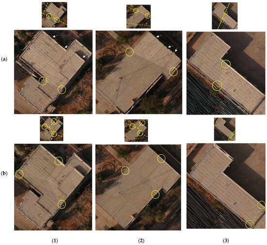
Figure 12.
The examples of differences along the seamlines on orthophotos in three areas (1), (2), and (3), generated using CF-based (a) and proposed method (b) methods, where seamlines cross the buildings. Seamlines are marked as yellow dashed-lines.
These results suggest that both methods performed well considering the crossing seamlines with the roadways, as shown in Figure 13(a1,b1) for dataset 1, which represented a hilly region. However, differences are seen in CF-based seamlines in dataset 2 (Figure 13(a2,a3)). As we can see in these figures, along the blue lines (Figure 13(a2)) and blue-white curve lines (Figure 13(a3)), the extruded roads, there are discontinuities as big as 2 pixels. Both the factors of image matching errors during the composition of individual orthophotos and reprojection errors during image rectification are involved in creating differences along the seamlines. The image blending technique can also reduce the remaining differences around the peripheries of seamlines [53].
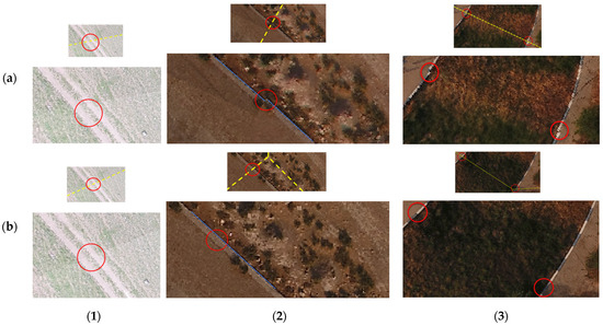
Figure 13.
The examples of differences along the seamlines on orthophotos, generated using methods of CF-based (a) and proposed method (b), where seamlines cross the roads (red circle) in areas (1), (2), and (3). Seamlines are marked as yellow dashed-lines.
In addition to the large double-mapped areas and discrepancies along the seamlines, the CF-based method produced orthophotos with more sawtooth effects. Some examples are indicated with white arrows in Figure 11(a2,a3) and Figure 12(a1,a2). Here, the sawtooth effect is likely impacted by changes in the reprojection error. The reprojection error of each DSM point during image rectification is affected by the distance to the camera, as well as the accuracy of the images’ external orientation parameters. In fact, when the image utilized in orthophoto generation is closer to the perpendicular direction of the point, the reprojection error is the lowest. This is guaranteed through the optimization method used in the proposed method. Also, the accuracy of the external orientation parameters of UAV images can be very different, since the quality and precision of UAV images may differ for reasons such as being more influenced by environmental factors, sensor fluctuations, and low flight height [54]. As a result, a point’s reprojection error differs depending on the UAV image.
4.2.3. Processing Time
The total processing times of the proposed and CF-based methods for large-scale orthophoto mosaic generation are recorded and listed in Table 2. Since the proposed method is developed to improve the efficiency of research [29], the processing times of this research for generating orthophoto mosaics are also included in this table for comparison. The times given for the proposed method are for a 3D coarse grid with a 30 cm × 30 cm dimension and the full orthophoto with a 3 cm × 3 cm resolution. Also, the CF-based orthophotos are produced with a resolution of 3 cm × 3 cm. Orthophoto mosaics by [29] are generated with a resolution of 3 cm × 3 cm as well. The dimensions of the orthophoto mosaic of dataset 1 are 11,530 × 9982, and the second dataset is 9739 × 8436.
Table 2.
The total processing times of the proposed method and CF-based method for large-scale orthophoto mosaic generation.
As shown in Table 2, compared to the CF-based method and research [29], in the first dataset, the processing times are decreased by 15 min and 8 min, respectively, representing a 46% and 32% reduction. In the second dataset, the processing times are reduced by 42 min and 28 min, respectively, which means approximately 45% and 35% reductions. According to Table 2, in the first dataset (38 images), the average processing time (per image) for the CF-based, method by [29], and the proposed method are 51 s, 39 s, and 27 s, respectively. In the second dataset (199 images), the times are 28, 24, and 15 s, respectively. As can be seen, the method proposed in this paper is faster than the one we developed in [29]. However, it can be noted that the average time does not have a linear relation to concerning the number of images. This is because, although the number of images in the first dataset is less than that of the second dataset, it includes more orthophoto pixels. Thus, its average time per image is higher. Indeed, in our technique, the factors influencing the processing time are mainly the number of images, the dimensions of the orthophoto mosaic, and the overlap between images.
4.3. Discussion
As mentioned above, two drone datasets were used to represent diverse terrains—a hilly area near Qazvin city (Dataset 1) and the relatively flat Golgir city in southern Iran (Dataset 2). The proposed method was evaluated against a common frame-to-frame (CF) method, focusing on double-mapped areas, discontinuities across the seamlines, and processing times. The proposed method effectively reduces double-mapped areas, particularly in areas with significant elevation changes, considering a closer distance to the camera during optimal image determination minimizes occluded areas, leading to superior results compared to the CF-based method. Seamlines generated by the proposed method exhibit fewer discrepancies, especially when crossing high-rise objects like buildings. In comparison, the CF-based method introduces errors along seamlines, with larger discrepancies and sawtooth effects.
The proposed method demonstrates a notable reduction in processing time compared to the CF-based method and Research [29]. In Dataset 1, a 46% and 32% reduction, respectively (15 min and 8 min), and in Dataset 2, a 45% and 35% reduction (42 min and 28 min) highlight the efficiency gains, making it a more time-effective solution. In summary, the proposed method offers a substantial improvement over traditional techniques, effectively addressing issues related to double-mapped areas, seamline discontinuities, and processing time. Its pixel-by-pixel approach and low-resolution grid-based seamline detection contribute to a more efficient and seamless orthophoto mosaic generation process. The experimental analysis validates its superiority, showcasing its potential for various applications in drone-based mapping applications.
5. Conclusions
The generation of large orthophoto mosaics from drone images is an essential task in most photogrammetry projects. For this, the original images are usually orthorectified individually using a DSM and then stitched together along some determined seamlines. Either frame-to-frame or multi-frame joint method can determine these seamlines. Unfortunately, such methods require substantial pre-processing, such as individual orthophoto generation, image registration, and overlap area extraction. In this paper, we proposed a simple yet effective and strong method that requires no additional pre-processing. The developed method focuses on generating a global pixel-by-pixel approach, enhancing the efficiency of existing methods while minimizing the processing time. It leverages optimal image determination at a low-resolution scale, forming seamlines from grouped optimal images and creating full-scale orthophoto mosaics. The proposed algorithm comprises three main stages: initial processing, low-resolution grid-based seamline detection, and full-resolution orthophoto mosaic generation. The initial step involves processing drone images, obtaining orientation parameters, sparse and dense point clouds, and a DSM. The low-resolution grid-based seamline detection involves determining optimal images for DSM points, forming seamline polygons, and establishing a seamline network. This network guides the creation of a complete orthophoto mosaic at full resolution. Optimal images are determined using a grid-to-camera distance principle, which results in reducing double-mapped areas and minimizing occlusion effects. The algorithm categorizes 3D grid points into polygons based on optimal images to form the seamlines network crucial for orthophoto mosaic generation. Unlike traditional methods, which work by stitching individual orthophotos, the proposed method generates the entire orthophoto mosaic in a single process, ensuring smoother, seamless results. The process involves identifying optimal images for full-resolution DSM points, with pixel values extracted through back-projection. This pixel-by-pixel approach enhances efficiency and eliminates the need for image registration and overlap extraction.
According to the assessments, our proposed method produces orthophoto mosaics with far less double mapped areas than Common frame-to-frame (CF)-based methods. Differences along the seamlines are negligible, even where they pass through buildings and extruded roads. Also, the sawtooth effect of the edges is considerably less than those of CF-based orthophoto mosaics. These improvements can enhance the quality of orthophoto mosaics. The proposed method is also more time-efficient than traditional algorithms. However, our methods used grid-to-camera distance to select optimum images for orthophoto mosaic construction. In this regard, we suggest studying other criteria such as viewing angle, distance from the occluded area, image quality, and reprojection error. It is also important to take into account the accuracy of the exterior orientation parameters when selecting the optimal image, which was not addressed in previous studies and is also not included in our research. This is particularly significant in areas that are forested and near water. Considering that exterior orientation parameters of UAV images can have highly varying accuracy due to their poor texture. So, the authors are considering providing a multi-criteria method for generating orthophoto mosaics in such datasets with higher accuracy and quality in future research.
Also, as mentioned in the text, we considered the distance between the low-resolution grid points to be between 10 to 20 times the original DSM interval. Here, we did not suggest a specific number, since our main goal was only to show that the smaller the low-resolution grid is, the faster the computations will be. This issue can also be explored further in future studies.
Author Contributions
Conceptualization, M.V.; Data curation, M.S.; Formal analysis, M.V. and M.S.; Funding acquisition, S.P.; Investigation, M.V., M.S., S.P. and A.M.; Methodology, M.V. and M.S.; Project administration, M.V. and S.P.; Resources, M.V., M.S., S.P. and A.M.; Software, M.V. and M.S.; Supervision, M.V. and S.P.; Validation, M.V., M.S., S.P. and A.M.; Visualization, M.S.; Writing—original draft, M.V., M.S. and S.P.; Writing—review and editing, M.S., M.V., S.P. and A.M. All authors have read and agreed to the published version of the manuscript.
Funding
This research received no external funding.
Data Availability Statement
The data presented in this study are available on request from the corresponding author.
Acknowledgments
This paper is a part of the Ph.D. thesis of Maryam Sajadian at K.N. Toosi University of Technology. This paper is a collaborative work with the Artificial Intelligence Institute, Shaoxing University.
Conflicts of Interest
The authors declare no conflicts of interest.
References
- Wang, Q.; Yan, L.; Sun, Y.; Cui, X.; Mortimer, H.; Li, Y. True orthophoto generation using line segment matches. Photogramm. Rec. 2018, 33, 113–130. [Google Scholar] [CrossRef]
- Liu, Y.; Zheng, X.; Ai, G.; Zhang, Y.; Zuo, Y. Generating a high-precision true digital orthophoto map based on UAV images. ISPRS Int. J. Geo-Inf. 2018, 7, 333. [Google Scholar] [CrossRef]
- Lamsters, K.; Karušs, J.; Krievāns, M.; Ješkins, J. High-resolution orthophoto map and digital surface models of the largest Argentine Islands (the Antarctic) from unmanned aerial vehicle photogrammetry. J. Maps 2020, 16, 335–347. [Google Scholar] [CrossRef]
- Shoab, M.; Singh, V.K.; Ravibabu, M. High-Precise True Digital Orthoimage Generation and Accuracy Assessment based on UAV Images. J. Indian Soc. Remote Sens. 2022, 50, 613–622. [Google Scholar] [CrossRef]
- Badrloo, S.; Varshosaz, M.; Pirasteh, S.; Li, J. Image-based obstacle detection methods for the safe navigation of unmanned vehicles: A review. Remote Sens. 2022, 14, 3824. [Google Scholar] [CrossRef]
- Badrloo, S.; Varshosaz, M.; Pirasteh, S.; Li, J. A novel region-based expansion rate obstacle detection method for MAVs using a fisheye camera. Int. J. Appl. Earth Obs. Geoinf. 2022, 108, 102739. [Google Scholar] [CrossRef]
- Mousavi, V.; Varshosaz, M.; Remondino, F.; Pirasteh, S.; Li, J. A Two-Step Descriptor-Based Keypoint Filtering Algorithm for Robust Image Matching. IEEE Trans. Geosci. Remote Sens. 2022, 60, 1–21. [Google Scholar] [CrossRef]
- Biasion, A.; Dequal, S.; Lingua, A. A new procedure for the automatic production of true orthophotos. Int. Arch. Photogramm. Remote Sens. Spat. Inf. Sci. 2004, 35, 1682–1777. [Google Scholar]
- Zhou, G.; Chen, W.; Kelmelis, J.A.; Zhang, D. A comprehensive study on urban true orthorectification. IEEE Trans. Geosci. Remote Sens. 2005, 43, 2138–2147. [Google Scholar] [CrossRef]
- Sheng, Y. Minimising algorithm-induced artefacts in true ortho-image generation: A direct method implemented in the vector domain. Photogramm. Rec. 2007, 22, 151–163. [Google Scholar] [CrossRef]
- Chen, J.; Li, Z.; Peng, C.; Wang, Y.; Gong, W. UAV Image Stitching Based on Optimal Seam and Half-Projective Warp. Remote Sens. 2022, 14, 1068. [Google Scholar] [CrossRef]
- Song, M.; Ji, Z.; Huang, S.; Fu, J. Mosaicking UAV orthoimages using bounded Voronoi diagrams and watersheds. Int. J. Remote Sens. 2018, 39, 4960–4979. [Google Scholar] [CrossRef]
- Xandri, R.; Pérez-Aragüés, F.; Palà, V.; Arbiol, R. Automatic generation of seamless mosaics over extensive areas from high resolution imagery. In Proceedings of the World Multi-Conference on Systemics, Cybernetics and Informatics (WMSCI), Orlando, FL, USA, 10–13 July 2005. [Google Scholar]
- Yang, Y.; Gao, Y.; Li, H.; Han, Y. An algorithm for remote sensing image mosaic based on valid area. In Proceedings of the 2011 International Symposium on Image and Data Fusion, Chicago, IL, USA, 5–8 July 2011; pp. 1–4. [Google Scholar]
- Zhang, J.; Xu, S.; Zhao, Y.; Sun, J.; Xu, S.; Zhang, X. Aerial orthoimage generation for UAV remote sensing. Inf. Fusion 2023, 89, 91–120. [Google Scholar] [CrossRef]
- Zhang, Y.; Zhang, M.; Du, S.; Zou, Z.; Fan, C. Seamline optimisation for urban aerial ortho-image mosaicking using graph cuts. Photogramm. Rec. 2018, 33, 131–147. [Google Scholar] [CrossRef]
- Li, M.; Li, D.; Guo, B.; Li, L.; Wu, T.; Zhang, W. Automatic seam-line detection in UAV remote sensing image mosaicking by use of graph cuts. ISPRS Int. J. Geo-Inf. 2018, 7, 361. [Google Scholar] [CrossRef]
- Manandhar, P.; Jalil, A.; AlHashmi, K.; Marpu, P. Automatic Generation of Seamless Mosaics Using Invariant Features. Remote Sens. 2021, 13, 3094. [Google Scholar] [CrossRef]
- Qu, Z.; Wang, T.; An, S.; Liu, L. Image seamless stitching and straightening based on the image block. IET Image Process. 2018, 12, 1361–1369. [Google Scholar] [CrossRef]
- Tian, J.; Li, X.; Duan, F.; Wang, J.; Ou, Y. An efficient seam elimination method for UAV images based on wallis dodging and gaussian distance weight enhancement. Sensors 2016, 16, 662. [Google Scholar] [CrossRef]
- Chon, J.; Kim, H.; Lin, C.-S. Seam-line determination for image mosaicking: A technique minimizing the maximum local mismatch and the global cost. ISPRS J. Photogramm. Remote Sens. 2010, 65, 86–92. [Google Scholar] [CrossRef]
- Chen, G.; Chen, S.; Li, X.; Zhou, P.; Zhou, Z. Optimal seamline detection for orthoimage mosaicking based on DSM and improved JPS algorithm. Remote Sens. 2018, 10, 821. [Google Scholar] [CrossRef]
- Nguyen, T.L.; Byun, Y.; Han, D.; Huh, J. Efficient seamline determination for UAV image mosaicking using edge detection. Remote Sens. Lett. 2018, 9, 763–769. [Google Scholar] [CrossRef]
- Yuan, S.; Yang, K.; Li, X.; Cai, H. Automatic Seamline Determination for Urban Image Mosaicking Based on Road Probability Map from the D-LinkNet Neural Network. Sensors 2020, 20, 1832. [Google Scholar] [CrossRef] [PubMed]
- Pan, J.; Wang, M.; Li, D.; Li, J. Automatic generation of seamline network using area Voronoi diagrams with overlap. IEEE Trans. Geosci. Remote Sens. 2009, 47, 1737–1744. [Google Scholar] [CrossRef]
- Mills, S.; McLeod, P. Global seamline networks for orthomosaic generation via local search. ISPRS J. Photogramm. Remote Sens. 2013, 75, 101–111. [Google Scholar] [CrossRef]
- Li, L.; Yao, J.; Lu, X.; Tu, J.; Shan, J. Optimal seamline detection for multiple image mosaicking via graph cuts. ISPRS J. Photogramm. Remote Sens. 2016, 113, 1–16. [Google Scholar] [CrossRef]
- Li, L.; Yao, J.; Shi, S.; Yuan, S.; Zhang, Y.; Li, J. Superpixel-based optimal seamline detection in the gradient domain via graph cuts for orthoimage mosaicking. Int. J. Remote Sens. 2018, 39, 3908–3925. [Google Scholar] [CrossRef]
- Sajadian, M.; Varshosaz, M. True orthophoto mosaic generation: A simple and fast method. J. Geomat. Sci. Technol. 2023, 12, 75–94. [Google Scholar] [CrossRef]
- Li, X.; Feng, R.; Guan, X.; Shen, H.; Zhang, L. Remote sensing image mosaicking: Achievements and challenges. IEEE Geosci. Remote Sens. Mag. 2019, 7, 8–22. [Google Scholar] [CrossRef]
- Gharibi, H.; Habib, A. True orthophoto generation from aerial frame images and LiDAR data: An update. Remote Sens. 2018, 10, 581. [Google Scholar] [CrossRef]
- de Oliveira, H.C.; Dal Poz, A.P.; Galo, M.; Habib, A.F. Surface gradient approach for occlusion detection based on triangulated irregular network for true orthophoto generation. IEEE J. Sel. Top. Appl. Earth Obs. Remote Sens. 2018, 11, 443–457. [Google Scholar] [CrossRef]
- Mousavi, V.; Varshosaz, M.; Remondino, F. Using information content to select keypoints for UAV image matching. Remote Sens. 2021, 13, 1302. [Google Scholar] [CrossRef]
- Zhu, H.; Jiang, Y.; Zhang, C.; Liu, S. Research on mosaic method of uav low-altitude remote sensing image based on sift and surf. J. Phys. Conf. Ser. 2022, 2203, 012027. [Google Scholar] [CrossRef]
- Pan, J.; Fang, Z.; Chen, S.; Ge, H.; Hu, F.; Wang, M. An improved seeded region growing-based seamline network generation method. Remote Sens. 2018, 10, 1065. [Google Scholar] [CrossRef]
- Li, L.; Tu, J.; Gong, Y.; Yao, J.; Li, J. Seamline network generation based on foreground segmentation for orthoimage mosaicking. ISPRS J. Photogramm. Remote Sens. 2019, 148, 41–53. [Google Scholar] [CrossRef]
- Chen, Y.; Briese, C.; Karel, W.; Pfeifer, N. True orthophoto generation using multi-view aerial images. Int. Arch. Photogramm. Remote Sens. Spat. Inf. Sci. 2014, 40, 67. [Google Scholar] [CrossRef]
- Wang, M.; Yuan, S.; Pan, J.; Fang, L.; Zhou, Q.; Yang, G. Seamline determination for high resolution orthoimage mosaicking using watershed segmentation. Photogramm. Eng. Remote Sens. 2016, 82, 121–133. [Google Scholar] [CrossRef]
- Laaroussi, S.; Baataoui, A.; Halli, A.; Khalid, S. A dynamic mosaicking method based on histogram equalization for an improved seamline. Procedia Comput. Sci. 2018, 127, 344–352. [Google Scholar] [CrossRef]
- Schickier, W.; Thorpe, A. Operational procedure for automatic true orthophoto generation. Int. Arch. Photogramm. Remote Sens. 1998, 32, 527–532. [Google Scholar]
- Balletti, C.; Guerra, F.; Lingua, A.; Rinaudo, F. True digital orthophoto of the San Marco Basilica in Venice. Int. Arch. Photogramm. Remote Sens. Spat. Inf. Sci. 2003, 34, 43–48. [Google Scholar]
- Nielsen, M.Ø. True Orthophoto Generation. Master’s Thesis, Technical University of Denmark, Lyngby, Denmark, 2004. [Google Scholar]
- Ettarid, M.; M’h, A.A.; Aloui, R. Digital True Orthophotos Generation. 2005. Available online: http://www.semanticscholar.org (accessed on 22 February 2024).
- Hanusch, T. Texture Mapping and True Orthophoto Generation of 3D Objects; ETH: Zurich, Switzerland, 2010. [Google Scholar]
- Barazzetti, L.; Brumana, R.; Oreni, D.; Previtali, M.; Roncoroni, F. True-orthophoto generation from UAV images: Implementation of a combined photogrammetric and computer vision approach. ISPRS Ann. Photogramm. Remote Sens. Spat. Inf. Sci. 2014, 2, 57–63. [Google Scholar] [CrossRef]
- Hu, Y.; Stanley, D.; Xin, Y. True ortho generation of urban area using high resolution aerial photos. ISPRS Ann. Photogramm. Remote Sens. Spat. Inf. Sci. 2016, 3, 3–10. [Google Scholar] [CrossRef]
- Fangming, Q.; Wei, L. Research on the Occlusion Processing Method for True Orthophoto. In Proceedings of the 2013 Seventh International Conference on Image and Graphics, Qingdao, China, 26–28 July 2013; pp. 328–331. [Google Scholar]
- Dostal, C.; Yamafune, K. Photogrammetric texture mapping: A method for increasing the Fidelity of 3D models of cultural heritage materials. J. Archaeol. Sci. Rep. 2018, 18, 430–436. [Google Scholar] [CrossRef]
- Boccardo, P.; Dequal, S.; Lingua, A.; Rinaudo, F. True digital orthophoto for architectural and archaeological applications. Int. Arch. Photogramm. Remote Sens. 2001, 34, 50–55. [Google Scholar]
- Wang, X.; Xie, J. A method for true orthophoto generation based on projection and iteration strategy. ISPRS Ann. Photogramm. Remote Sens. Spat. Inf. Sci. 2012, 4, 311–314. [Google Scholar] [CrossRef]
- Haggag, M.; Zahran, M.; Salah, M. Towards automated generation of true orthoimages for urban areas. Am. J. Geogr. Inf. Syst. 2018, 7, 67–74. [Google Scholar]
- Sheng, Y.; Gong, P.; Biging, G.S. True orthoimage production for forested areas from large-scale aerial photographs. Photogramm. Eng. Remote Sens. 2003, 69, 259–266. [Google Scholar] [CrossRef]
- Li, X.; Hui, N.; Shen, H.; Fu, Y.; Zhang, L. A robust mosaicking procedure for high spatial resolution remote sensing images. ISPRS J. Photogramm. Remote Sens. 2015, 109, 108–125. [Google Scholar] [CrossRef]
- Nasrullah, A.R. Systematic Analysis of Unmanned Aerial Vehicle (UAV) Derived Product Quality. Master’s Thesis, University of Twente, Twente, The Netherlands, 2016. [Google Scholar]
Disclaimer/Publisher’s Note: The statements, opinions and data contained in all publications are solely those of the individual author(s) and contributor(s) and not of MDPI and/or the editor(s). MDPI and/or the editor(s) disclaim responsibility for any injury to people or property resulting from any ideas, methods, instructions or products referred to in the content. |
© 2024 by the authors. Licensee MDPI, Basel, Switzerland. This article is an open access article distributed under the terms and conditions of the Creative Commons Attribution (CC BY) license (https://creativecommons.org/licenses/by/4.0/).