Article

Use of Geoinformatics for the Digitization and Visualization of Sensitive Space in the Urban Landscape: A Case Study of the Gross-Rosen Sub-Camps Systems

by
Sebastian Różycki
1,*,
Marek Michalski
2 and
Aleksandra Kobielec
3
1
Faculty of Geodesy and Cartography, Warsaw University of Technology, 1 Sq. Politechniki, 00-661 Warsaw, Poland
2
Independent Researcher, 41-808 Zabrze, Poland
3
Gross-Rosen Museum in Rogoźnica, Ofiar Gross Rosen 26, 58-152 Rogoźnica, Poland
*
Author to whom correspondence should be addressed.
Remote Sens. 2024, 16(5), 783; https://doi.org/10.3390/rs16050783
Submission received: 24 January 2024 / Revised: 15 February 2024 / Accepted: 21 February 2024 / Published: 24 February 2024
(This article belongs to the Special Issue Applications of Remote Sensing in Landscape Archaeology)

Abstract

:
Geospatial technologies enable accurate and detailed documentation of cultural heritage sites. They allow for the creation of digital representations of these sites that can be shared with interested audiences. Given the above, this paper presents the possibility of using archival data to reconstruct the topography of two German labor camps, Dyhernfurth I and II, which operated during World War II. To perform this task, multi-source archival data was obtained and interpreted. These data came from various sources: archives, historical institutes, and museums. The results of the study were presented to the staff of the Gross-Rosen Museum, who anticipated the possibility of using the proposed tools in the management of other labor camps. The proposed methodology can be replicated at other locations and easily implemented by other martyrdom museums involved in the preservation of cultural heritage.

1. Introduction

GIS systems are useful tools for supporting the digitalization process. Geospatial data assist the care of memorial sites that are the material evidence of crucial events in history. These activities are also aimed at disseminating knowledge about objects and facts related to places bearing the traces of mass crimes committed by totalitarian regimes [1,2,3,4,5]. The digital age has revolutionized the methods that allow us to restore, preserve, and protect our cultural heritage [6,7]. Thanks to advances in technology, we have access to tools such as geospatial data that will enable us to create new documentation to preserve historic sites. Furthermore, historical perspectives are essential for making well-informed choices regarding environmental challenges, such as spatial planning, sustainable development, or climate adaptation [8]. This paper focused on finding a location and reconstructing the topography of Dyhernfurth labor camps operating at the Sarin and Tabun war gas factories during World War II. These camps were part of the sub-camps working within the Gross-Rosen concentration camp. The research undertaken was intended to support and describe the processes of interpretation of archival materials, field research, and for the protection of historical cultural heritage. Institutions and authorities responsible for the preservation of heritage sites must have not only historical documents (e.g., witness accounts), but also cartographic documents (e.g., plans), which are essential materials for making well-informed and lawful decisions related to heritage, thus helping to preserve heritage sites for future generations and improving management and promotion of tourism [9,10]. In the case of the two camps studied and the other sub-camps included in the Gross-Rosen camp, their exact location and current state of preservation still need to be discovered. The tragic history of the site contrasts with the operating chemical plant. The fenced-off area of the factory, where the camp was probably located, and the lack of formal and material monuments make the site stand out from similar sites associated with martyrdom history in Poland [11]. The lack of traces of the camp’s boundary in the current fabric of the city causes problems for clearly identifying its extent. The presented research was divided into three phases: the first, at the desk, included reconstructing the camp’s topography based on archival data. A plan and archival aerial photographs from the Second World War were used at this stage. The second phase, in the field, was related to the on-site inventory of camp remains. The third and final phase, on the desk, was the development of a geoportal providing access to data from the first and second research phases. Spatial data prepared and provided in this way encourages citizens to learn new facts, add further information, and share their historical and sensitive knowledge, which is a public contribution to heritage development.

2. Study Area: Historical Setting

Germans began constructing large factories in Germany (Falkenhagen) and later in Dyhernfurth, Poland (part of Germany at the time) for the massive production of tabun, sarin, cyanogen chloride, and hydrocyanic acid [12]. The decision to construct a facility in Dyhrnfurth was taken as early as December 1939. The operating company of the state-owned plant was Anorgana GmbH, a subsidiary of I.G. Farbenindustrie AG [13]. Dyhernfurth started operating in 1942 and tabun was first produced in May 1943. Sarin followed in June 1944 [14]. In 1943, I.G. Farbenindustrie formed an agreement with the KL Gross-Rosen camp administration, as a result of which two sub-camps, Dyhernfurth I and II, were set up in the vicinity of the Anorgana production plant. Currently, Brzeg Dolny (Figure 1) is a town in Poland in the Lower Silesian Voivodeship. The town is situated on the right bank of the Oder river, 31 km north-west of Wrocław, thus forming an extension of the urban-industrial Wrocław agglomeration.
At the end of World War II, Soviet troops captured the Dyhernfurth facility, dismantled it, and moved it, along with the key personnel, to the former Soviet Union, where production of the agents commenced in 1946 [15]. The facility premises were contaminated, which made it difficult to secure and then reconstruct the production plant. Despite problems, production of sodium hypochlorite commenced as early as 1946, with the use of raw materials left by the Germans. In 1947 the facility produced sodium hypochlorite and sulphur chloride. In the 1950s and 1960s, the plants expanded to the point where, to attract workers, they took over some of the functions of the poor local administration, and undertook and financed numerous investments to enrich the city’s infrastructure. The camp buildings became part of the factory. After the end of the war, the area was fenced off, and access was only possible after obtaining a pass. Consequently, the camp buildings became an inaccessible part. The lack of access probably caused problems in undertaking activities related to commemorating the remains of the camp.

2.1. Labour Camp Dyhernfurth I

Labour camp Dyhernfurth I was set up in the late spring or early summer of 1943 and was located directly on the factory premises, near to the workshop in which the prisoners were put to work [16,17,18,19,20,21]. It was a small sub-camp, as at its peak activity, it held 300 prisoners. These were mainly Poles, but Russians, Czechs, Germans, and Roma were also among the inmates. Files of the majority of the interned bore an “R.U” note (Germ. Rückkehr unerwünscht—return undesirable) [22]. The Anorgana factory produced mainly the tabun chemical warfare agent (T38), which is an extremely toxic liquid. Since filling bombs with the gas and checking their tightness, as well as cleaning the underground gas tanks and checking the installations in the tanks were the prisoners’ jobs, overexposure was a frequent occurrence, despite protective clothing [23,24].

2.2. Labour Camp Dyhernfurth II

The date of the establishment of Dyhernfurth II camp can be only approximated to the summer or autumn of 1943 [17,18,19,20]. Located about 1 km away from Anorgana, in a small thicket, the camp consisted of barracks, a few of which were one-storey, brick buildings while the majority were built of wood. Two of the barracks were intended as a camp hospital (Germ. Revier). In the first months of the camp’s existence, namely in 1943, the number of inmates did not exceed 450 people [21]. However, in January 1944, a vast influx of prisoners was observed. The highest known number of inmates was recorded on 27 October 1944 and amounted to 3037 prisoners, which equalled merely one third of the number originally intended (9700) [22]. The inmates were employed in the construction of extensions of the Anorgana facility, mainly doing heavy earthwork or construction work, transporting cement and gravel or unloading railway shipments; some others worked as locksmiths, administrators, painters or draftsmen.

3. Materials and Methods

The archive materials described in this section in the form of aerial photographs allows for the interpretation and analysis of the camps area. As part of the study performed, a current spatial data set, available for the surveyed area, was also acquired and described. This material helps to relate the results of analyses and interpretations of archival materials to the current terrain situation. This is of great importance for planning field studies, both noninvasive and invasive, as well as for future memorializing.

3.1. Aerial Photographs from the United States National Archives and Record Administration (NARA)

An aerial photo at a scale of 1:9800, taken on 13 September 1944 by the 106 Squadron RAF (No. 106 Squadron RAF of Royal Air Force), was used for photo interpretation in the study area. A series (Sortie: 106G/2850) of photographs were taken with a 914 mm lens mounted on Fairchild F.52 camera body [25,26]. An identical series is also available in the National Collection of Aerial Photography in Scotland (NCAP). The cost of acquiring scans of the images and the license based on the public domain favors the NARA archive. The obtained images are of very good quality. The aerial photographs were obtained and scanned with the EPSON Expression 12000 XL scanner (Epson, Shinjuku, Tokyo, Japan) at 1200 DPI. The original films available in the NARA archive were scanned. In order to perform a proper integration of spatial data with actual data, it was also necessary to perform an orthorectification of aerial photograph [27]. The orthorectification of the 1944 aerial photo was performed using the PCI Geomatica software (PCI Geomatica OrthoEngine, Quebec, QC, Canada) [28].

3.2. Aerial Photographs, Orthophotomaps, Laser Scanning Data, and Spatial Databases from the Head Office of Geodesy and Cartography in Poland

An orthophotograph is a product obtained via geometric processing of an aerial photograph. In Poland, orthophotomaps collected in the central geodetic and cartographic resource are made available by the head office of Geodesy and Cartography [29,30]. As part of the performed task, aerial photographs and orthophotomaps of a camps taken in 1974, 2004, 2009, and 2021 were collected. The selection of photographs was preceded by an analysis of the possible use of available photogrammetrical materials in selected Polish archives. The parameters of these photogrammetrical materials are presented in Table 1. The workflow with digital aerial mapping cameras changes compared to the traditional way with film-based analogue cameras. Photo scale is replaced by ground sample distance (GSD) [31,32]. The GSD is the distance in meters between two adjacent pixel centers measured on the ground. It depends on the sensor aperture and the flight altitude [33]. In the case of acquiring a scan of an aerial photograph, we have provided a scale, and for digital orthophotomaps, a GSD. The 1974 photograph was orthorectified in an identical way to the 1944 Allied aerial photograph.
The laser scanning product is a collection of points in a spatial coordinate system (X, Y, Z), the so-called point cloud [34,35]. These are the points of reflection from the surface of the land and objects “protruding” above that surface, such as buildings, trees, or power line cables. The most common use of laser scanning is construction of a terrain model (digital terrain model (DTM), or digital elevation model (DEM)), which represent the physical surface of the terrain with its morphological forms. In this case, the points resulting from the reflection from objects “protruding” above the surface of the terrain must be removed. The point cloud used came from the ISOK project (Information System for National Coverage against Extraordinary Hazards). It is publicly available in two density standards: (1) 12 and (2) 4 points per m2. The vertical accuracy of the point cloud for standard 1 was ≤0.15 and ≤0.10 m for standard 2, respectively [36,37]. The point cloud was measured using airborne laser scanning technology. The survey used a point cloud with a density of 4 points per square meter, acquired in November 2011. The point cloud allowed for the generation of a DTM with a 0.5 m raster [38,39]. It was processed in the Relief Visualization Toolbox (RVT v. 2.2.1, Research Centre of the Slovenian Academy of Sciences and Arts, Ljubljana, Slovenia) software [40], which resulted in the following products covering the areas of research:
  • shaded relief maps;
  • visualizations based on principle component analysis (PCA);
  • sky view factor;
  • topographical openness;
  • local dominance [41,42].
The above products, resulting from the processing of the digital elevation model, contain valuable information about the analyzed area. Historical or archaeological research was most frequently in the form of shaded relief maps, slope maps, aspect maps, and visibility maps [43,44,45,46,47]. Appropriate parameters for such processing, selected according to the characteristics of the surface, highlight the characteristics of the terrain which are particularly useful for analyzing the activities carried out in the area under consideration. Processing of DTM was treated as supporting material in this paper.
The BDOT10k spatial database was used to present the actual land topography data. The Database of Topographic Objects (BDOT10k) is a vector (object-oriented) database containing the spatial location of topographic objects along with their characteristics. The content and detail of the BDOT10k database corresponds to a topographic map at a scale of 1:10,000, where the thematic scope includes, among others, information on: water network, communication network, utility network, land cover, buildings, structures and facilities, land use complexes, protected areas, and territorial subdivisions. The database covers the entire area of Poland and is successively updated [48].

3.3. Data Interpretation Process and Visualisations

To define the boundaries of the camps and for the sake of interpretation, archival and current data relating to the surrounding area were used. Archival data in the form of aerial photographs taken during the Second World War were the main material for recreating the boundaries of the camp and for analyzing the historical coverage of the area. In some cases, laser scanning data showing the terrain is a very useful source of information. Current data in the form of aerial photographs was used to georeference the archival data and allowed for the visualization of the selected archival objects on the current background. QGIS v. 3.18.3 software and ArcGIS Pro v. 3.0 (ESRI, Inc., Redlands, CA, USA) was used for practical interpretation and analysis of the terrain. In the first stage, vector layers were acquired, showing the camp border and the terrain objects seen in the 1944 photograph: internal and external fencing, buildings, assembly area, and air gaps. All the data obtained from the interpretation was added to the National Spatial Reference System: system 1992. This helped generate geodetic coordinates of the selected objects. In the final stage, data were made available in the form of a geoportal. The ArcGIS On-line cloud software (ESRI, Inc., Redlands, CA, USA) was used to make the data available [49,50]. ArcGIS Online systems can run on handheld computing devices such as tablets and smartphones [51,52], so in fieldwork they are is simple to use as they have built-in GPS receivers for localization. This helped researchers locate the remains of the camp in the field during the site visit as well as the Museum staff in the future camp inventory work. Based on the integration of spatial data, the applied methodology is often used in Europe in the context of projects concerning the material remains of camps [53,54] or sites related to the armed conflict [55,56] during the Second World War. The case study of Dyhernfurth camps was similar to other sites investigated by researchers in the European area.

4. Results

Based on the aerial photos taken by the Allied forces over Dyhernfurth (Brzeg Dolny), an interpretation of the buildings and infrastructure of the two Nazi German sub-camps AL (Germ. ArbeitsLager) Dyhernfurth I and Dyhernfurth II (Figure 2) was completed. Historical documents such as factory plans and testimonies of witnesses who testified after the war were also used. A significant difference between the two lies in the fact that Dyhernfurth I, as opposed to Dyhernfurth II, was a camp located on the premises of the Anorgana G.m.b.H. company, producing and enhancing the chemical warfare agents sarin and tabun.

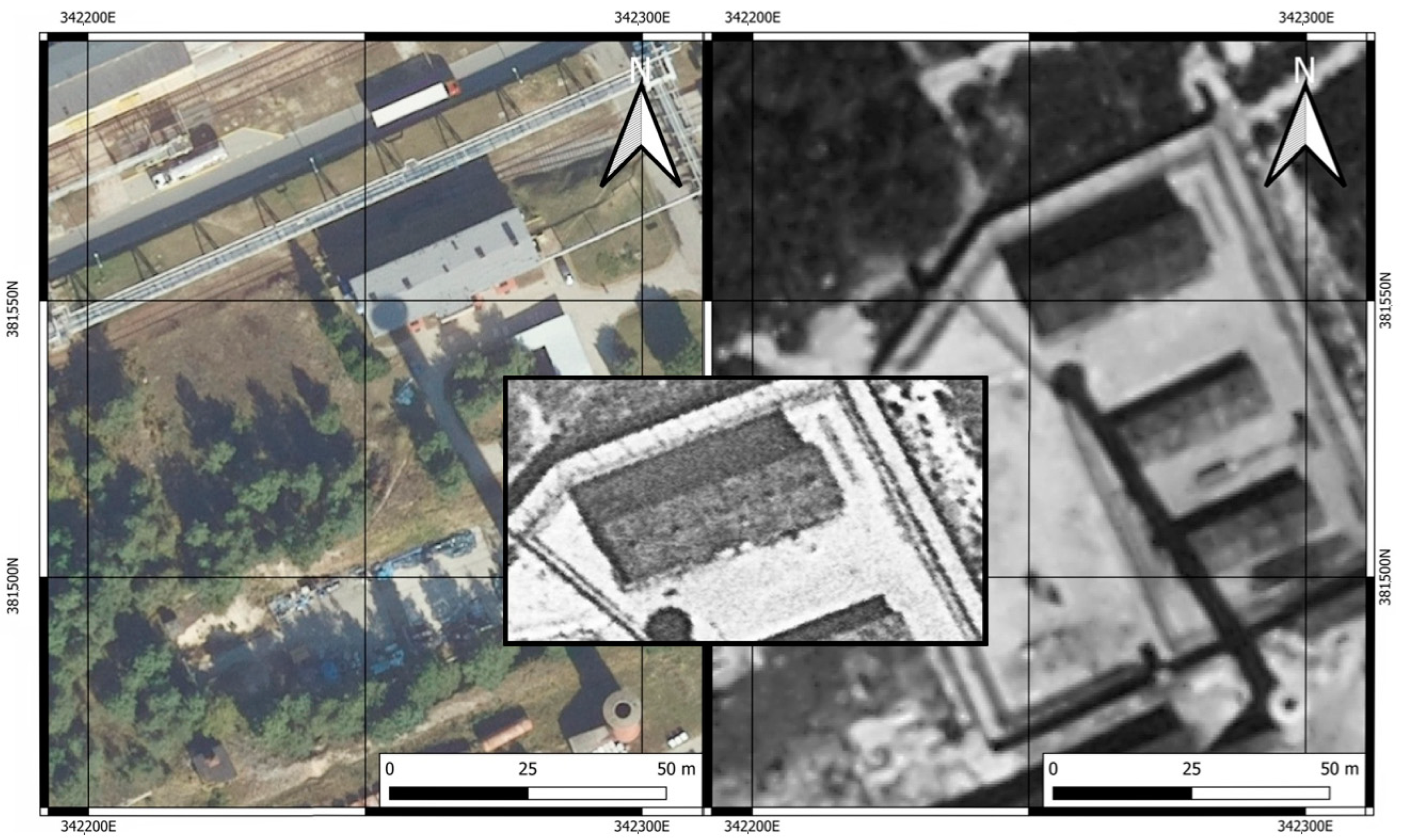
4.1. Sub-Camp Dyhernfurth 1 (AL Dyhernfurth I)

The camp was located directly on the premises of the Anorgana G.m.b.H. production facility. The area of the sub-camp, calculated with use of the outline of its external fence, is around 7000 m2. It was surrounded by a double fence, the outer fence being a wooden board fence whose purpose was to prevent observation of the activities inside the camp. It is possible that the uniform shadow on the ground seen in the aerial photo hints at such a kind of fence. The main inner fence, running parallel to the outer one, was made of wire. Lamps directed at the camp area were fixed to the poles of this fence. According to eyewitnesses, it was also an electric fence (Figure 3).
An extra fence ran across the sub-camp area, dividing it into two parts. Guard towers were placed along the fence. When the photo was taken, namely in September 1944, the sub-camp comprised two wooden barracks and one brick barracks. The size of the wooden barracks was 25 m by 8 m. The brick barracks was situated north of the wooden ones and its size was 32 m by 10 m (Figure 4).
One building was referred to by eyewitnesses as the one where the sub-camp’s staff, meaning SS officers, were and was near to the outer fence, outside the sub-camp area, towards the south. Its dimensions were 16 m by 4 m. The aerial photograph taken in September 1944 provided a basis for juxtaposing the vector layers showing the outlines of the buildings in existence in 1944 with the vector layer showing the present buildings. Superimposition of the two layers allowed for the observation that one of the buildings, namely the brick building situated in the northern part of the former AL Dyhernfurth I sub-camp, has survived till the present day. It is difficult to determine what has been changed in its structure over the years, yet, its outline as well as the location of the chimneys visible both in the photograph from 1944 and the one form 2022 have not changed (Figure 5 and Figure 6).

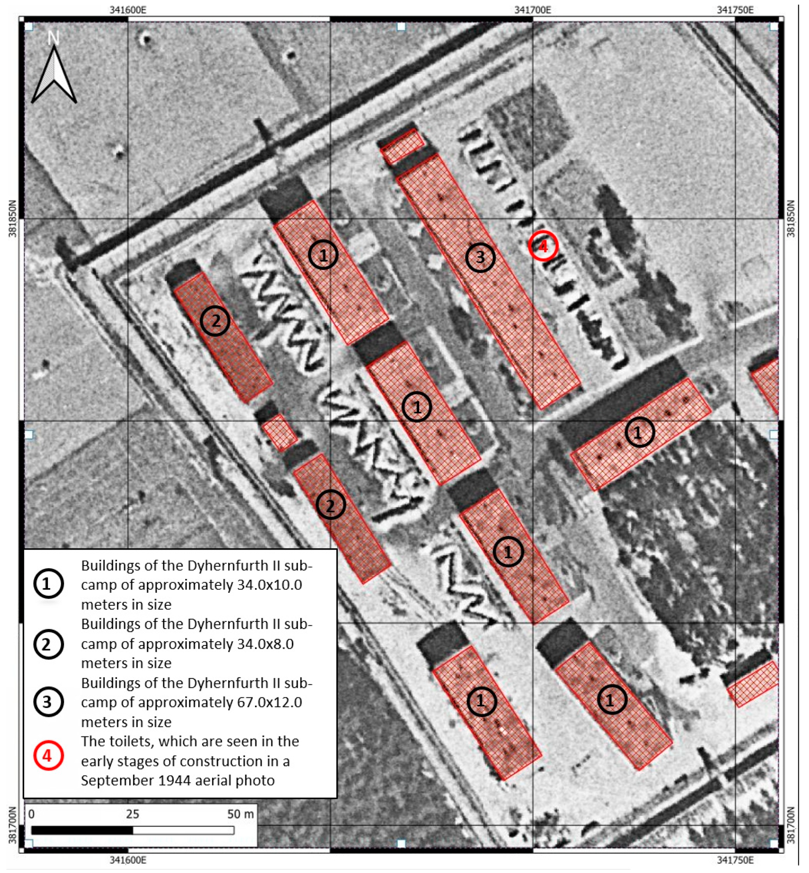
4.2. Sub-Camp Dyhernfurth 2 (AL Dyhernfurth II)

The sub-camp Dyhernfurth II was located north-east of the camp Dyhernfurth I, about 1000 m in a straight line away from it. It was situated outside the town of Dyhernfurth, on the edge of the thicket, sheltering it from the road running north. The area of the whole camp amounted to 42,000 m2, measured within the outline of the external fence. The sub-camp comprised more than 20 buildings of varied structure and size as well as in the materials used to construct them. Some of the buildings were situated in the area adjacent to the sub-camp itself. The sub-camp was surrounded with a double fence. The outer fence was a full panel fence, whose shadow can be seen along the northern and southern edge of the sub-camp. Data on the material used to construct the fence is lacking. The inner fence consisted of concrete poles between which a metal wire was stretched. Within the fence were 9 to 11 guard towers, whose shape is clearly visible and can be identified (Figure 7).
The camp could be entered through two gates. The first one was located at the end of the camp road while the second one was a double internal gate, being the entrance to the sub-camp itself. These gates were identified in the aerial photograph due to the shadow cast by the poles to which the gates were fixed. A roll call square of 73 m by 36 m in size was an integral part of the sub-camp. It was situated on a small rise that seemed elevated above the level of the camp road. At the time when the photograph was taken in September of 1944, at the edges of the roll call square certain structures can be seen whose shadow implies that these could be football goals. In the area of the sub-camp, six structures (Figure 8, no. 1) of around 34 m by 10 m in size can be distinguished. According to the accounts of former prisoners, these were two-storey, brick buildings. In the western area of the sub-camp, two structures of 33 m by 8 m (Figure 8, no. 2) in size can be distinguished. According to the accounts provide after the war, these one-storey buildings were made of wood or similar materials.
Both the shadows cast on the ground in the aerial photograph and the photographs taken in the 1970s indicate the varied heights of these buildings. Between two rows of these buildings, to the west, a stretch of air raid shelters was located. The biggest structure in the sub-camp was the building in its central part, 67 m by 12 m in size (Figure 8, no. 3). According to the accounts of former prisoners, between this building and the assembly ground, there were toilets, which can be seen in the early stages of their construction in the photograph from September 1944. The remaining structures in the area of the sub-camp itself, within the double fence, were three or four buildings located in the south-east corner of the camp. Furthermore, in this case, the creation of vector layers and the superimposition of these layers on the present-day materials (building layer) from the BDOT 10k allows for the identification of one of the buildings (Figure 9) as having a historical continuation up until today. However, it is difficult to determine how radical the changes may have been or whether the present-day building was erected in place of a demolished camp building.

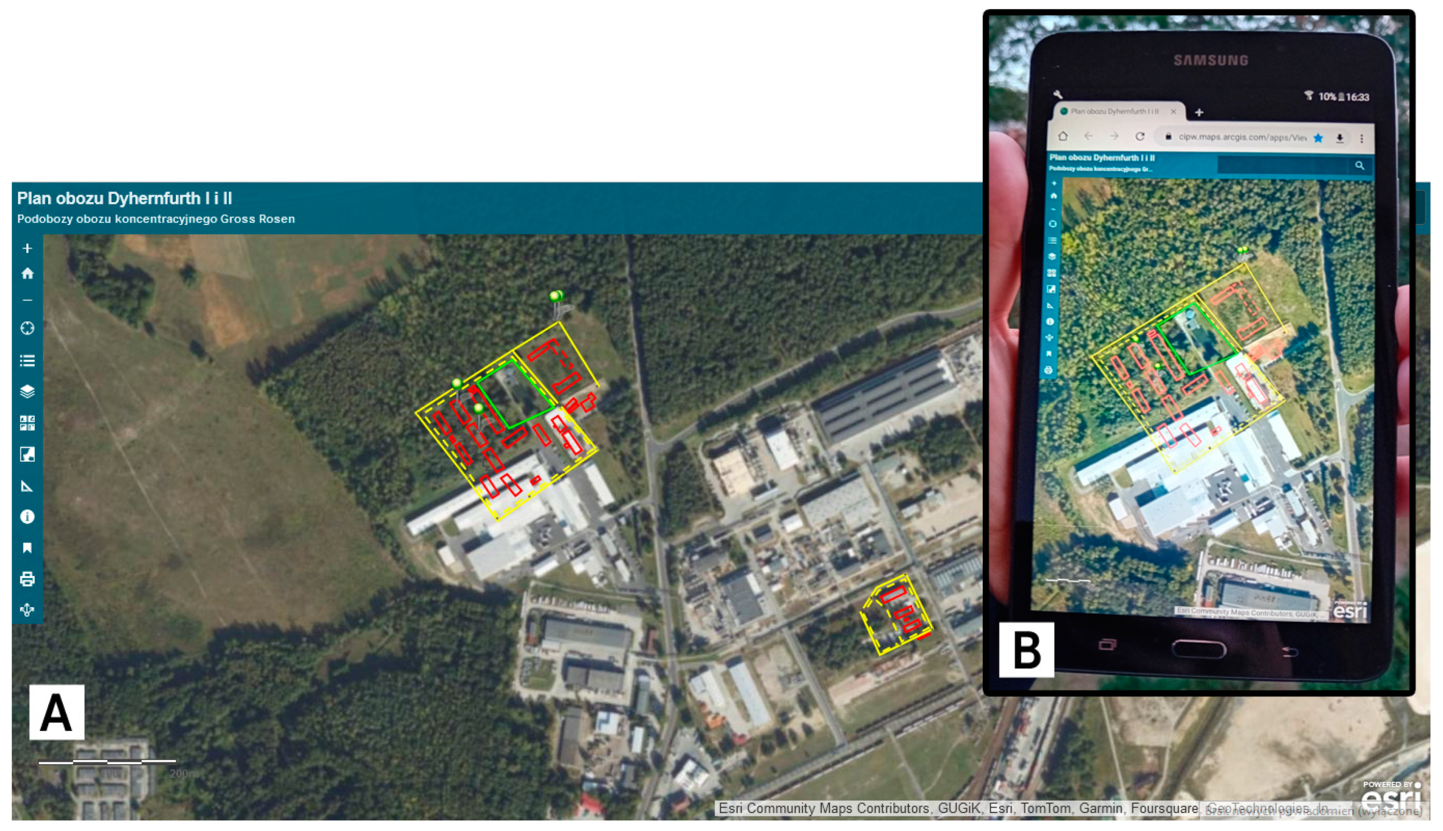
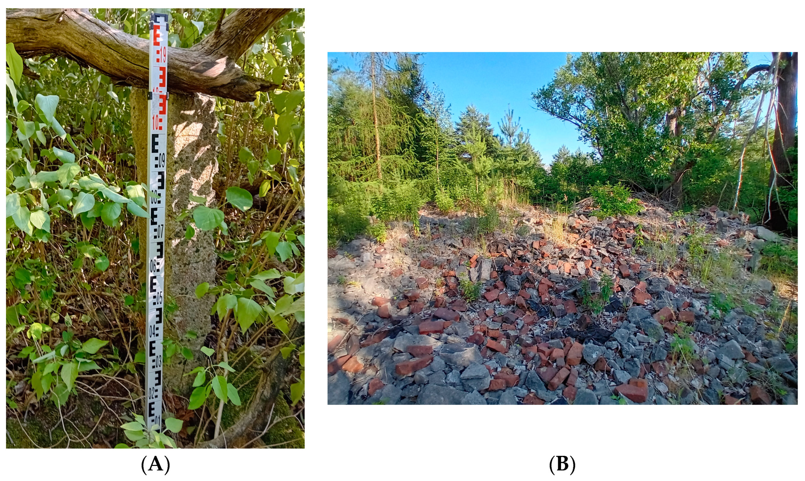
4.3. Implementing the Geoportal and Walk around the Surveyed Area of of the Camp Remains

Vector layers after creation were sent to the ArcGIS Online cloud (Figure 10). The proposed geoportal provides a simple user interface that enables the display of web maps with various configurable options: prints, length and area measurement capability, and layer visibility support (including transparency options). Such options available to non-specialist GIS users allow them to work productively with spatial data. After configuring the web application and adjusting the symbology of displayed layers, a site visit to make an inventory of the camp remains became possible (in July 2023).
The application was displayed on a mobile phone which enabled location in the field thanks to the embedded GPS receiver. A link to the designed geoportal in Polish and English language versions is available in the Supplementary Materials Section. The portal is under constant development. A walk around the surveyed area took place in the Dyhernfurth II camp, whose north-west part was not taken over by the Rokita S.A. factory after the war. Parts of the northern fence have survived in the form of remains of the poles and foundations (Figure 11A). The place where the buildings stood (two northern buildings marked with number 1 in Figure 8) is full of rubble of the shape roughly equivalent to the outlines drawn with use of the aerial photographs from 1944. It is safe to assume that these are the remains of the two barracks that were destroyed and whose remains collapsed. Remains of the foundations, brick walls, chimneys, and sewage pipes can be found on the ground (Figure 11B).

4.4. Laser Scanning Data and Products Analysis

Only for a small area of the AL Dyhernfurth II camp was it possible to analyze the suitability of the visualizations generated from the laser scanning data. SVF visualization (and others) were not successful in identifying the remains of buildings (Figure 12A). A similar image structure is only visible for the two buildings. However, the lack of terrain knowledge reduced the ability to precisely interpret these structures without a field visit. The profiles created (one is presented in Figure 12B) based on the laser scanning data also do not show clear structures close to the barracks footprint. They represent the debris of the barrack’s remains found in the field. Trees and vegetation make it difficult to interpret these structures on the actual orthophotos. In the example given, the use of multi-source data does not allow a correct description of the field remains without a field visit.

5. Discussion

The reconstruction of the topography of the Dyhernfurth I, and II camps makes it possible to start discussing how to develop strategies to ensure a balance between the operation and development of the industrial zone and the preservation of material cultural heritage. It should be remembered that the camps are located in a closed area, belonging to a factory associated with the chemical industry.
Only one building survives from the Dyhernfurth I camp, which today is used as an office. Its close location to the factory installations excludes it from being open to the public or any other commemoration. During the consultation (July 2023) with museum staff, it was agreed that it would be worth attempting a site visit to ascertain the state of preservation of the originality of the designated building. The present owners of the site may have documentation relating to the extension of this building. This would make it possible to reconstruct the camp building digitally. Attempts at commemoration must be undertaken with great sensitivity and considering not only the need to preserve historical memory but also the rights of the landowners. The actual development requirements of the site must be addressed. In Poland [57], as in Europe [58,59,60], there are problems with adequately commemorating the places associated with the period of tragedy related to the actions of the Second World War. For this reason, the research carried out makes sense and should be continued.
Camp Dyhernfurth II already has more potential for discovering historical, and sensitive values. The five barracks, which are located outside the factory site, have collapsed. However, they represent a material trace of the functioning camp as well as the fate of the prisoners working at the factory [61]. During the field inspection, it was observed that the former site had surrendered to vegetation, but traces of a poorly trodden path were still visible. It can be assumed that historians and searchers explored the area on their own.
The project aimed to complete an analysis of the former camps’ terrain during the so-called desk phase. Like with other similar studies on the reconstruction of the topography of camps operating during the Second World War [62,63,64,65], it was expected that the developed visualizations produced based on DEM would be significantly supported. However, the developed materials played a minor role at the desk research phase.
The physical remains of the Dyhernfurth II camp are not a tourist “attraction,” but planning, for example, a path leading to the remains of the original fence could be the first step in restoring a sense of physical cultural heritage for future visitors who want to visit the site. A small parking lot and an information board may be built along the main road. All proposals and ideas related to any new commemoration require consultation with the Gross-Rosen Museum, the factory owners, as well as Brzeg Dolny city officials. The designed application (Geoportal) was shared with the staff of the Museum Gross-Rosen. It allows for the discussion of the historical potential of the site using archival georeferenced spatial data and current land use.

6. Conclusions

The use of archival aerial and ground-level photos allowed for the reconstruction of the topography of AL Dyhernfurth camps. The presented methods of data processing showed the possibilities and limitations of the laser scanning visualization methods used in the context of topography of former camps. Archival materials played an important role in the reconstruction of facilities related to the World War II period [66,67,68]. Materials in the form of plans as well as the Geoportal created enabled estimation and inventory of the remains in the field. The materials and geoportal can also aid in restoring memory of these places. Preparing the drafts and locating the remains of the camp in the field contributed to a discussion on commemorating the prisoners and victims of the camps. A memorial commemorating the victims of the Gross-Rosen sub-camps was erected as early as 1949. It is located in front of the entrance to the factory, in Henryka Sienkiewicza Street, around 1 km away from the actual location of the camp. The information of the preserved parts of the fence and remains of the two barracks permit planning of the preservation and commemoration process [69]. We propose to commence inventory of numerous sub-camps (around 100) located in Dolny Śląsk, Sudety, and Ziemia Lubuska. Preliminary archival queries have revealed that aerial photos and witness testimonies for sub-camps operating within the Gross-Rosen concentration camp are available in American and Polish archives. If the method proposed in this article is used, work on inventory of the other sub-camps can be commenced in the near future, in cooperation between scientists and the employees of the Museum. The availability and dissemination of historical information about the location and history of the camps will significantly help preserve the heritage and increase awareness of its value. It will also help future efforts to preserve the heritage based on articles, online mapping services and applications for tourism. In the future, the development with 3D modeling and augmented reality will help to more involve and interest the local population and tourists. As spatial science develops, GIS in combination with remote sensing and other technologies, could better support sustainable development, taking into account the tragic events, the remains of many of which are located (but forgotten) in urban areas.

Supplementary Materials

The following supporting information are available at: https://cipw.maps.arcgis.com/apps/View/index.html?appid=0206c9c19fd34ced8f225943335381fd (accessed on 20 February 2024), Geoportal—Plan obozu Dyhernfurth I i II in the Polish language version; https://cipw.maps.arcgis.com/apps/View/index.html?appid=fdc01ca1fd574596b9906f02f75d1c238c (accessed on 20 February 2024), Geoportal—Plan of Labour Camp Dyhernfurth I and II in the English language version.

Author Contributions

Methodology, S.R. and M.M.; software, M.M. and S.R.; validation, S.R.; resources, M.M. and S.R.; writing—original draft preparation, S.R. and M.M.; visualization, M.M. and S.R.; historical background, A.K.; project administration, S.R.; funding acquisition, S.R.; writing—review and editing, S.R. All authors have read and agreed to the published version of the manuscript.

Funding

This research was funded by Minister of Education and Science Republic of Poland, grant number NdS/544021/2021/2022 under the program: Science for Society.

Data Availability Statement

The data from the head office of Geodesy and Cartography are available publicly. The photographs available in the National Archives and Records Administration are shared on a public domain basis. The data can be requested from the corresponding authors.

Acknowledgments

The authors are sincerely grateful to the Gross-Rosen Museum in Rogoźnica for their support of this research. We acknowledge financial support by the Faculty of Geodesy and Cartography within the funding program Open Access Publishing.

Conflicts of Interest

The authors declare no conflicts of interest.

Correction Statement

This article has been republished with a minor correction to the Funding statement. This change does not affect the scientific content of the article.

References

  1. Abramov, A.E.; Veselovskaya, A.; Dolgov, A.V.; Engovatova, M.B.; Mednikova, S.; Nikitin, S.; Safarov, A. Forensic Archaeology in the Russian Federation. In Forensic Archaeology: Global Perspectives; Groen, M., Márquez-Grant, M., Janaway, M., Eds.; Wiley-Blackwel: Chichester, UK, 2015; pp. 139–148. [Google Scholar]
  2. Djurić, M.; Pavlović, T. Excavation of Mass Graves with Serbian Context: Complexity of the Political Milieu. Forensic Sci. Int. 2021, 319, 110657. [Google Scholar] [CrossRef]
  3. Kobiałka, D.; Kostyrko, M.; Wałdoch, F.; Kość-Ryżko, K.; Rennwanz, J.; Rychtarska, M.; Nita, D. An archaeology of Death Valley, Poland. Antiquity 2021, 95, e29. [Google Scholar] [CrossRef]
  4. Bem, M. Sobibór Niemiecki Ośrodek Zagłady 1942–1943; Muzeum Hitlerowskiego Obozu Zagłady w Sobiborze: Sobibór, Poland, 2012. [Google Scholar]
  5. Gilead, I.; Haimi, Y.; Mazurek, W. Excavating Nazi extermination centres. Present Pasts 2010, 1, 12. [Google Scholar] [CrossRef]
  6. Masciotta, M.; Sánchez-Aparicio, L.; Bishara, S.; Oliveira, D.; González-Aguilera, D.; García-Alvarez, J. Digitization of cultural heritage buildings for preventive conservation purposes. In Proceedings of the 12th International Conference on Structural Analysis of Historical Constructions (SAHC), Barcelona, Spain, 16–18 September 2020. [Google Scholar]
  7. Doğan, Y.; Yakar, M. GIS and three-dimensional modeling for cultural heritages. Int. J. Geosci. 2018, 3, 50–55. [Google Scholar] [CrossRef]
  8. Santos, B.; Gonçalves, J.; Almeida, P.G. GIS-based inventory for safeguarding and promoting Portuguese glazed tiles cultural heritage. Herit. Sci. 2003, 11, 133. [Google Scholar] [CrossRef]
  9. Emanuele, P.; Maietti, F.; Di Giulio, R.; Schippers-Trifan, O.; Van Delft, A.; Bruinenberg, S.; Olivadese, R. BIM-based Cultural Heritage Asset Management Tool. Innovative Solution to Orient the Preservation and Valorization of Historic Buildings. Int. J. Archit. 2001, 15, 897–920. [Google Scholar]
  10. Sánchez-Aparicio, L.J.; Masciotta, M.G.; García-Alvarez, J.; Ramos, L.F.; Oliveira, D.V.; Martín-Jiménez, J.A.; Monteiro, P. Web-GIS approach to preventive conservation of heritage buildings. Autom. Constr. 2020, 118, 103304. [Google Scholar] [CrossRef]
  11. Drozdzewski, D. When the Everyday and the Sacred Collide: Positioning Płaszów in the Kraków Landscape. Landsc. Res. 2014, 39, 251–258. [Google Scholar] [CrossRef]
  12. Wertejuk, Z.; Koch, M.; Marciniak, W. Recovered Old Arsenical and ‘Mustard’ Munitions in Poland: Technologies, Plans and Problems. In Arsenic and Old Mustard: Chemical Problems in the Destruction of Old Arsenical and ‘Mustard’ Munitions; Bunnett, J., Mikołajczyk, M., Eds.; Springer: Dordrecht, The Netherlands, 1998; pp. 91–104. [Google Scholar]
  13. Friedrich, B.; Hoffmann, D.; Renn, J.; Schmaltz, F.; Wolf, M. One Hundred Years of Chemical Warfare: Research, Deployment, Consequences; Springer International Publishing: Cham, Switzerland, 1997. [Google Scholar]
  14. Ballantyne, B.; Marrs, T.C. Clinical and Experimental Toxicology of Organophosphates and Carbamates; Elsevier: London, UK, 1992. [Google Scholar]
  15. Bajgar, J.; Fusek, J.; Kassa, J.; Kuca, K.; Jun, D. Global impact of chemical warfare agents used before and after 1945. In Handbook of Toxicology of Chemical Warfare Agents; Gupta, R., Ed.; Elsevier: London, UK, 1992; pp. 27–36. [Google Scholar]
  16. Sprenger, I. Gross-Rosen. In Ein Konzentrationslager in Schlesien; Böhlau Verlag: Cologne, Germany, 1996. [Google Scholar]
  17. Czernik, H. Filie obozu koncentracyjnego w Brzegu Dolnym. In Studia nad Faszyzmem i Zbrodniami Hitlerowskimi; Jońc, K., Ed.; Państwowe Wydawnictwo Naukowe; Oddział Wrocławski: Wrocław, PL, USA, 1974. [Google Scholar]
  18. Olszyna, R. Żydzi w KL Dyhernfurth. KL Gross-Rosen—Wybór Artykułów; Muzuem Gross Rosen: Wałbrzych, PL, USA, 2005. [Google Scholar]
  19. Hałgas, K. Byłem w KL Gross-Rosen i Dyhernfurth. Wspomnienia Lekarza-Więźnia; Muzuem Gross Rosen: Wałbrzych, PL, USA, 2013. [Google Scholar]
  20. Konarzewski, N. Powrót Niepożądany. Wspomnienia Romana Konarzewskiego; Self Publishing: Warszawa, PL, USA, 2021. [Google Scholar]
  21. Sula, D. Żydzi Polscy w Konzentrationslager Gross-Rosen; Muzuem Gross Rosen: Wałbrzych, PL, USA, 2020. [Google Scholar]
  22. Kobielec, A. Dyhernfurth I, Dyhernfurth II (Brzeg Dolny). In Der Ort des Terrors. Geschichte der Nationalsozialistischen Konzentrationslager; C. H. Beck: München, DE, USA, 2007; pp. 278–286. [Google Scholar]
  23. Schmidt, U. Accidents and experiments: Nazi chemical warfare research and medical ethics during the Second World War. In Military Medical Ethics for the 21st Century; Gross, M., Carrick, D., Eds.; Routledge: London, UK, 2013; pp. 225–244. [Google Scholar]
  24. Koelle, G. Organophosphate Poisoning—An Overview. Toxicol. Sci. 1981, 1, 129–134. [Google Scholar] [CrossRef]
  25. Redecker, A.P. Historical aerial photographs and digital photogrammetry for impact analyses on derelict land sites in human settlement areas. Int. Arch. Photogramm. Remote Sens. Spat. Inf. Sci. 2008, 37, 5–10. [Google Scholar]
  26. Różycki, S.; Karwel, A.K.; Kurczyński, Z. German Extermination Camps on WWII Reconnaissance Photographs. Orthorectification Process for Archival Aerial Images of Cultural Heritage Sites. Remote Sens. 2023, 15, 2587. [Google Scholar] [CrossRef]
  27. Bożek, P.; Janus, J.; Mitka, B. Analysis of Changes in Forest Structure using Point Clouds from Historical Aerial Photographs. Remote Sens. 2019, 11, 2259. [Google Scholar] [CrossRef]
  28. Kamola, A.; Różycki, S.; Bylina, P.; Lewandowski, P.; Burakowski, A. Forgotten Nazi Forced Labour Camps: Arbeitslager Riese (Lower Silesia, SE Poland) and the Use of Archival Aerial Photography and Contemporary LiDAR and Ground Truth Data to Identify and Delineate Camp Areas. Remote Sens. 2020, 12, 1802. [Google Scholar] [CrossRef]
  29. Dyba, K.; Nowosad, J. rgugik: Search and Retrieve Spatial Data from the Polish Head Office of Geodesy and Cartography in R. J. Open Source Softw. 2021, 6, 29–48. [Google Scholar] [CrossRef]
  30. Doskocz, A. The actual state of the geodetic and cartographic resources and legislation in Poland. Open Geosci. 2022, 15, 20220458. [Google Scholar] [CrossRef]
  31. Neumann, K. Operational aspects of digital aerial mapping cameras. The International Archives of the Photogrammetry. Int. Arch. Photogramm. Remote Sens. 2004, 35, 222–225. [Google Scholar]
  32. Felipe-García, B.; Hernández-López, D.; Lerma, J.L. Analysis of the ground sample distance on large photogrammetric surveys. Appl. Geomat. 2012, 4, 231–244. [Google Scholar] [CrossRef]
  33. Paixão, A.; Muralha, J.; Resende, R. Close-Range Photogrammetry for 3D Rock Joint Roughness Evaluation. Rock. Mech. Rock. Eng. 2022, 55, 3213–3233. [Google Scholar] [CrossRef]
  34. Chen, C.; Guo, J.; Wu, H.; Li, Y.; Shi, B. Performance Comparison of Filtering Algorithms for High-Density Airborne LiDAR Point Clouds over Complex LandScapes. Remote Sens. 2021, 13, 2663. [Google Scholar] [CrossRef]
  35. Kurczyński, Z. Fotogrametria, 1st ed.; PWN S.A.: Warsaw, Poland, 2014. [Google Scholar]
  36. Kurczyński, Z.; Bakuła, K. Generowanie referencyjnego numerycznego modelu terenu o zasięgu krajowym w oparciu o lotnicze skanowanie laserowe w projekcie ISOK. In Monografia “Geodezyjne Technologie Pomiarowe”: Wydanie Specjalne; Kurczyński, Z., Ed.; Zarząd Główny Stowarzyszenia Geodetów Polskich: Warsaw, Poland, 2013; pp. 59–68. [Google Scholar]
  37. Kurczyński, Z. Airborne Laser Scanning in Poland—Between Science and Practice. Archives of Photogrammetry. Cartogr. Remote Sens. 2019, 31, 105–133. [Google Scholar]
  38. Bakuła, K.; Ostrowski, W.; Zapłata, R.; Kurczyński, Z.; Kraszewski, B.; Stereńczak, K. Zalecenia w Zakresie Pozyskiwania, Przetwarzania, Analizy i Zastosowania Danych LIDAR w Celu Rozpoznania Zasobów Dziedzictwa Archeologicznego w Ramach Programu AZP; Politechnika Warszawska: Warszawa, Poland, 2016. [Google Scholar]
  39. Banaszek, Ł. Lotniczy skaning laserowy w polskiej archeologii. Czy w pełni wykorzystywany jest potencjał prospekcyjny metody? Folia Praehist. Posnan. 2014, 19, 207–251. [Google Scholar] [CrossRef]
  40. Kokalj, Ž.; Hesse, R. Airborne Laser Scanning Raster Data Visualization: A Guide to Good Practice; Založba ZRC: Ljubljana, Slovakia, 2017; Volume 14. [Google Scholar]
  41. Kokalj, Ž.; Zakšek, K.; Oštir, K.; Pehani, P.; Čotar, K.; Somrak, M.; Kokalj, Ž. Relief Visualization Toolbox, ver. 2.2. 1 Manual. Remote Sens. 2016, 3, 398–415. [Google Scholar]
  42. Štular, B.; Kokalj, Ž.; Oštir, K.; Nuninger, L. Visualization of lidar-derived relief models for detection of archaeological features. J. Archaeol. Sci. 2012, 39, 3354–3360. [Google Scholar] [CrossRef]
  43. Doneus, M. Openness as Visualization Technique for Interpretative Mapping of Airborne LiDAR Derived Digital Terrain Models. Remote Sens. 2013, 5, 6427–6442. [Google Scholar] [CrossRef]
  44. Brașoveanu, C.; Mihu-Pintilie, A.; Brunchi, R.-A. Inside Late Bronze Age Settlements in NE Romania: GIS-Based Surface Characterization of Ashmound Structures Using Airborne Laser Scanning and Aerial Photography Techniques. Remote Sens. 2023, 15, 4124. [Google Scholar] [CrossRef]
  45. Ortiz-Villarejo, A.J.; Gutiérrez Soler, L.-M. A Low-Cost, Easy-Way Workflow for Multi-Scale Archaeological Features Detection Combining LiDAR and Aerial Orthophotography. Remote Sens. 2021, 13, 4270. [Google Scholar] [CrossRef]
  46. Kokalj, Z.; Zaksek, K.; Ostir, K. Application of sky-view factor for the visualisation of historic landscape features in lidar-derived relief models. Antiquity 2011, 85, 263–273. [Google Scholar] [CrossRef]
  47. Becker, D.; De Andrés-Herrero, M.; Willmes, C.; Weniger, G.-C.; Bareth, G. Investigating the Influence of Different DEMs on GIS-Based Cost Distance Modeling for Site Catchment Analysis of Prehistoric Sites in Andalusia. ISPRS Int. J. Geo-Inf. 2017, 6, 36. [Google Scholar] [CrossRef]
  48. Dz.U. 2011 nr 279 poz. 1642. Rozporządzenie Ministra Spraw Wewnętrznych i Administracji z dnia 17 listopada 2011 r. w Sprawie Bazy Danych Obiektów Topograficznych Oraz Bazy Danych Obiektów Ogólnogeograficznych, a Także Standardowych Opracowań Kartograficznych. Available online: https://isap.sejm.gov.pl/isap.nsf/DocDetails.xsp?id=WDU20112791642 (accessed on 14 February 2024).
  49. Nowak, M.M.; Dziób, K.; Ludwisiak, Ł.; Chmiel, J. Mobile GIS applications for environmental field surveys: A state of the art. Glob. Ecol. Conserv. 2020, 23, e01089. [Google Scholar] [CrossRef]
  50. De Miguel González, R.; De Lázaro Torres, M.L. WebGIS implementation and effectiveness in secondary education using the digital atlas for schools. J. Geog. 2020, 119, 74–85. [Google Scholar] [CrossRef]
  51. Phantuwongraj, S.; Chenrai, P.; Assawincharoenkij, T. Pilot Study Using ArcGIS Online to Enhance Students’ Learning Experience in Fieldwork. Geosciences 2021, 11, 357. [Google Scholar] [CrossRef]
  52. Tripcevich, N. Flexibility by design: How mobile GIS meets the needs of archaeological survey. Cartogr. Geogr. Inf. Sci. 2004, 31, 137–151. [Google Scholar] [CrossRef]
  53. Grabowski, R.; Olsen, B.; Pétursdóttir, Þ.; Witmore, C. Teillager 6 Sværholt: The archaeology of a World War II prisoner of war camp in Finnmark, arctic Norway. Fennosc. Archaeol. 2014, 31, 3–24. [Google Scholar]
  54. Seitsonen, O.; Herva, V.P. Forgotten in the wilderness: WWII German PoW camps in Finnish Lapland. In Archaeologies of Internment; Springer: New York, NY, USA, 2011; pp. 171–190. [Google Scholar]
  55. Van der Schriek, M.; Beex, W. The application of LiDAR-based DEMs on WWII conflict sites in the Netherlands. J. Confl. Archaeol. 2017, 12, 94–114. [Google Scholar] [CrossRef]
  56. Van der Schriek, J.; van der Schriek, M. Metal Detecting: Friend or Foe of Conflict Archaeology? Investigation, Preservation and Destruction on WWII sites in the Netherlands. J. Community Archaeol. Heritage. 2014, 1, 228–244. [Google Scholar] [CrossRef]
  57. Sensacyjne Ustalenia Naukowców Dotyczące Kompleksu Riese. Teraz Wielu Mieszkańców Może Mieć Spory Problem. Available online: https://walbrzych.wyborcza.pl/walbrzych/7,178336,30631727,chca-by-riese-stalo-sie-zabytkiem-trwa-kilkanascie-postepowan.html (accessed on 14 February 2024).
  58. Gillian, C. Examining the memorialscape of occupation and liberation: A case study from the Channel Islands. Int. J. Herit. Stud. 2012, 18, 174–193. [Google Scholar]
  59. Antkowiak, M.; Völker, E. Dokumentiert und konserviert. Ein Außenlager des Konzentrationslagers Sachsenhausen in Rathenow. Landkreis Havelland. Archäologie Berl. Brandenbg. 2000, 1999, 147–149. [Google Scholar]
  60. Carr, G.; Colls, C.S. Taboo and sensitive heritage: Labour camps, burials and the role of activism in the Channel Islands. Int. J. Herit. Stud. 2016, 22, 702–715. [Google Scholar] [CrossRef]
  61. Szacka, B.; Castle, M. Polish Remembrance of World War II. Int. J. of Sociol. 2006, 36, 8–26. [Google Scholar] [CrossRef]
  62. Kiarszys, G.; Banaszek, Ł. Dostrzec i zrozumieć. Porównanie wybranych metod wizualizacji danych ALS wykorzystywanych w archeologii. Folia Praehist. Posnan. 2017, 22, 233–270. [Google Scholar] [CrossRef]
  63. Kobiałka, D.; Kostyrko, M.; Lokś, A.; Karski, K.; Rezler-Wasielewska, V.; Stanek, P.; Wickiewicz, A.; Góra, E.; Tomczak, S.; Pawleta, M. “Hell camp” hidden in the forest—The materiality of Stalag VIII B (344) Lamsdorf. J. Confl. Archaeol. 2023, 18, 97–124. [Google Scholar] [CrossRef]
  64. Kostyrko, M.; Kobiałka, D. Small and large heritage of the Great War: An archaeology of a prisoner of war camp in Tuchola, Poland. Landsc. Res. 2020, 45, 583–600. [Google Scholar] [CrossRef]
  65. Colls, C.S.; Kerti, J.; Colls, K. Tormented Alderney: Archaeological Investigations of the Nazi Labour and Concentration Camp of Sylt. Antiquity 2020, 94, 512–532. [Google Scholar] [CrossRef]
  66. Juhász, A.; Mihályi, B. Object and event reconstruction (WW II) with GIS. Int. Arch. Photogramm. Remote Sens. Spat. Inf. Sci. 2006, 36, 145–149. [Google Scholar]
  67. Maio, C.V.; Tenenbaum, D.; Brown, C.; Mastone, V.T.; Gontz, M. Application of geographic information technologies to historical landscape reconstruction and military terrain analysis of an American Revolution Battlefield: Preservation potential of historic lands in urbanized settings, Boston, Massachusetts, USA. J. Cult. Herit. 2013, 14, 317–331. [Google Scholar] [CrossRef]
  68. Albuquerque, M.; Sanz, G.; Oliveira, S.; Martínez-Alegría, R.; Antunes, R. Spatio-temporal groundwater vulnerability assessment-a coupled remote sensing and GIS approach for historical land cover reconstruction. Water Resour. Manag. 2013, 27, 4509–4526. [Google Scholar] [CrossRef]
  69. Collado, A.; Mora-Navarro, G.; Heras, V.; Lerma, J.L. A Web-Based Geoinformation System for Heritage Management and Geovisualisation in Cantón Nabón (Ecuador). ISPRS Int. J. Geo-Inf. 2022, 11, 4. [Google Scholar] [CrossRef]
Figure 1. The location of the labor camps Dyhernfurth I and II selected for detailed analysis [© ESRI basemaps, OpenStreetMap—Open Database License].
Remotesensing 16 00783 g001
Figure 2. Location of the camps in Dyhernfurth. The 1944 aerial photograph and topographic map at the scale 1:25,000 were used as base layers [© Head Office of Geodesy and Cartography, NARA]. Coordinate grid: PL–1992 (EPSG: 2180).
Remotesensing 16 00783 g002
Figure 3. Comparison of a ground-level photo taken after the end of the war with elements seen in the September 1944 aerial photo. The 1944 aerial photograph was used as a base layer [© NARA]. The ground photo is from the collection of the Gross-Rosen Museum in Rogoźnica. Coordinate grid: PL–1992 (EPSG: 2180).
Remotesensing 16 00783 g003
Figure 4. Vector layers based on a 1944 aerial photograph. Two smaller wooden barracks are marked, as well as one larger brick barracks to the north. The 1944 aerial photograph was used as a base layer [© NARA]. Coordinate grid: PL–1992 (EPSG: 2180).
Remotesensing 16 00783 g004
Figure 5. Comparison of buildings that existed in 1944, part of the Dyhernfurth I sub-camp, with the buildings in use today. Presented in vector form, the contemporary building outlines, are from the Building and Land Registry and BDOT 10k. The 1944 aerial photograph was used as a base layer [© NARA]. Coordinate grid: PL–1992 (EPSG: 2180).
Remotesensing 16 00783 g005
Figure 6. Most likely the only remaining brick building that was part of the Dyhernfurth I sub-camp during World War II. Image from left: the 2021 orthophotomap. Right: the 1944 aerial photograph [© Head Office of Geodesy and Cartography, NARA]. Coordinate grid: PL–1992 (EPSG: 2180).
Remotesensing 16 00783 g006
Figure 7. Dyhernfurth II sub-camp with the most important building presented as a vector layer. The 1944 aerial photograph was used as a base layer [© NARA]. Coordinate grid: PL–1992 (EPSG: 2180).
Remotesensing 16 00783 g007
Figure 8. Marked camp buildings located in the western part of the Dyhernfurth II sub-camp along with their dimensions. The 1944 aerial photograph was used as a base layer [© NARA]. Coordinate grid: PL–1992 (EPSG: 2180).
Remotesensing 16 00783 g008
Figure 9. Comparison of buildings that existed in 1944, part of the Dyhernfurth II sub-camp, with the buildings in use today. Presented in vector form, the contemporary building outlines are from the Building and Land Registry and BDOT 10k. The 2021 orthophotomap was used as a base layer [© Head Office of Geodesy and Cartography].
Remotesensing 16 00783 g009
Figure 10. Geoportal build on ArcGIS On-line (ESRI) cloud with the topography of the Dyhernfurth camps with the ability to overlay current spatial databases. Application displayed on the: (A) web browser, (B) android tablet in the field.
Remotesensing 16 00783 g010
Figure 11. Former AL Dyhernfurth II camp. On the left (A): the remains of a fence post; right (B): remains of the barracks. Photos: S. Różycki.
Remotesensing 16 00783 g011
Figure 12. Former AL Dyhernfurth II camp. (A) SVF image (radius 5 m), and camp buildings (red outlines from a 1944 aerial photo) located in the western part of the Dyhernfurth II sub-camp. The remains of building marked with the number 1. are presented on Figure 8. (B) Visualization of the profile cut (the profile vector A–B shown on Figure 12A as yellow line) made through a structure that is a trace of the two barracks [© Head Office of Geodesy and Cartography].
Remotesensing 16 00783 g012
Table 1. Obtained aerial photographs and orthophotomaps from the head office of Geodesy and Cartography.
No.The Date the Photograph Was TakenPicture/Ortho TypeTechnical Specifications
11 November 2021RGB, CIRFormat: GeoTIFF
GSD: 25 cm
22009RGBFormat: GeoTIFF
GSD: 50 cm
32004PanchromaticFormat: GeoTIFF
GSD: 50 cm
416 September 1974PanchromaticScale 1:25,000
Disclaimer/Publisher’s Note: The statements, opinions and data contained in all publications are solely those of the individual author(s) and contributor(s) and not of MDPI and/or the editor(s). MDPI and/or the editor(s) disclaim responsibility for any injury to people or property resulting from any ideas, methods, instructions or products referred to in the content.

