Abstract
We present a technique for the detection of vertebrate skeletons buried at shallow depths through the use of a ground-penetrating radar (GPR). The technique is based on the acquisition of high-resolution data by medium-to-high frequency GPR antennas and the analysis of the radar profiles by a new forward modelling method that is applied on a set of representative traces. This approach allows us to obtain synthetic traces that can be used to build detailed reflectivity diagrams that plot spikes with a distinct amplitude and polarity for each reflector in the ground. The method was tested in a controlled experiment performed at the top of Cerro Los Quesos, one of the most fossiliferous localities in the Ica Desert of Peru. We acquired GPR data at the location of a partially buried fossil skeleton of a large whale and analyzed the reflections associated with the bones using the new technique, determining the possible signature of vertebrae, ribs, the cranium (including the rostrum), and mandibles. Our results show that the technique is effective in the mapping of buried structures, particularly in the detection of tiny features, even below the classical (Ricker and Rayleigh) estimates of the vertical resolution of the antenna in civil engineering and forensic applications.
1. Introduction
Classical methods of analyzing near-surface radar data generally rely on the visual inspection and interpretation of reflection profiles (e.g., [1]) and sometimes on the inverse modelling of the acquired data (e.g., [2]). These methods have been successfully applied in several fields, from archaeological research to civil engineering, to detect relatively large structures buried at a shallow depth, but suffer from severe limitations when the target has a thickness below the Ricker or Rayleigh estimates of the GPR antenna vertical resolution. In this paper, we present a solution to the problem of detecting tiny structures in the shallow subsurface. Specifically, we address the problem of mapping the presence of skeletons in the context of paleontological research. Rather than being based on data inversion, the proposed method uses forward modelling to map anomalies in the electric properties underground along the vertical traces of radar profiles. Therefore, we will refer to this method as trace analysis. The anomalies are always revealed by pairs of strong amplitude reflectivity spikes with opposite polarity, with the bound regions having a dielectric permittivity much higher or lower than the surrounding material. Then, a reconstruction of the buried structures can be obtained by correlating the reflectivity peaks between traces. An advantage of this technique is that it allows us to reveal the presence of very thin features with an anomalous dielectric permittivity encapsulated in a homogeneous material, particularly buried bones, but can be extended to reveal the presence of small cracks, the thin lens of liquid contaminants, etc.
Apparently, GPR applications are not affected by issues related to vertical resolution, as one can always choose an antenna with a sufficiently high central frequency for the kind of targets that are being mapped. However, the higher the vertical resolution, the smaller the depth of penetration becomes. In addition to this, for any assigned antenna, the visual interpretation of radar profiles can be a very hard and subjective task. The technique described below should not be considered as a method to improve the resolution of GPR antennas. It simply provides an aid for the interpretation of the acquired data for an arbitrary antenna, especially in the presence of thin features. Compared to classical qualitative methods of analyzing GPR data, our approach can be considered semi-quantitative, because the visual analysis of radar profiles is always assisted by the forward modelling of key traces from these profiles, which provides additional high-resolution information about the buried structures. Here, we show that the trace analysis technique is effective in the detection of vertebrate skeletons, even when using an intermediate-resolution 400 MHz antenna. The controlled experiment described below was performed in one of the most fossiliferous localities of the Ica Desert of Peru, a true fossil-lagerstätte [3]. The results obtained through the study of a ~15-meter-long partially buried whale specimen indicate that the technique has the potential to allow the identification of skeleton components such as vertebrae, ribs, and skulls.
The Rayleigh estimate of the GPR antenna vertical resolution is usually calculated as λD/4, λD being the dominant wavelength of the signal [4,5]. This quantity is defined, in turn, as the following product: λD = vb, where v is the velocity of the electromagnetic waves within the target layer and b is the breadth of the electromagnetic pulses reflected to the GPR antenna [6]. The resolution is further reduced by the presence of noise and is lower for pulses that are reflected at a higher depth, because the attenuation tends to increase the dominant wavelength. In fact, many authors believe that a practical estimate of the resolution for GPR antennas is between λD/3 and λD/2 (e.g., [7]). The thin-beds problem has been addressed in several studies since the 1950s in the context of exploration seismology. Ricker [8] solved the problem of seismic resolution for the first time by recognizing that a seismogram, in the absence of noise, can be reconstructed by the superposition of wavelets with a simple mathematical expression. He showed that modelling seismograms through these wavelets provides a vertical resolution δz = λD/4.62, slightly better than the classical Rayleigh limit δz = λD/4. Widess [9] further reduced the threshold of resolution to δz = λD/8 by considering the composition of wavelets with opposite polarity, which are reflected by the upper and lower interfaces of a thin high-velocity layer. Finally, Kallweit and Wood [6], in an attempt to unify the Rayleigh, Ricker, and Widess criteria, showed that the practical limit actually coincides with the Rayleigh λD/4 resolution.
In more recent years, the thin-beds problem has been subject to revaluation by GPR practitioners, especially in stratigraphic and forensic applications. For example, an interesting study on the reflectivity of thin sedimentary structures in the vadose zone [10] showed that these beds generate interference between reflected wavelets, so that they can be detected only on detailed reflectivity plots, not by the visual inspection of radar profiles. The authors of this study performed indirect measurements of the dielectric permittivity from vertical transects in trenches and used these data to build high-resolution synthetic traces and reflectivity plots, which were compared with corresponding traces on the acquired GPR profiles. Unfortunately, this technique cannot be applied in most practical situations, as the compilation of dielectric permittivity profiles by the direct measurement of textural characteristics and the amount of water retention is a time-consuming laboratory practice. In principle, the presence of thin beds in sedimentary deposits can be revealed by a spectral shift of the reflected signal towards higher frequencies [11], but this approach would require a reference spectrum and, in any cases, it does not provide information about the depth and nature of the lamination. Below, we show that the time resolution that can be obtained with trace analysis is bounded only by the data sampling interval, which is well below the Rayleigh resolution.
2. Geological Setting of the Study Area
The East Pisco Basin is part of the forearc region of southern Peru that lies immediately landward of an area where the aseismic Nazca Ridge impinges on the South American margin (Figure 1). Our study area is placed at the top of Cerro los Quesos (CLQ) hill, one of the most representative localities of the Ica Desert fossil-lagerstätte [12]. Here, the Upper Miocene strata of the Pisco Formation are exposed and have been divided into six informal members (designated by the letters A through F in ascending stratigraphic order [12], see Supplementary Materials Figure S1). The latter include fifteen litho-stratigraphic markers that can be traced laterally for several tens of kilometers along the western side of the Ica Valley [13].
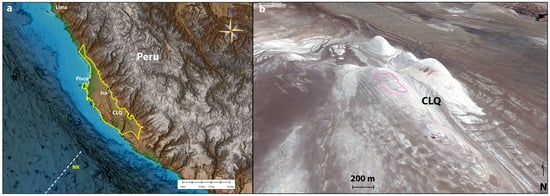
Figure 1.
Physiography of the study area. (a) Boundaries of the Pisco Basin (yellow line); CLQ = Cerro Los Quesos; NR = Nazca Ridge; (b) survey area at Cerro Los Quesos (purple line). The topography is slightly exaggerated.
The stratigraphic interval investigated in the present study represents a portion of the F member located above the Pelicano marker bed (see Supplementary Materials Figure S1). The radiometric (40Ar/39Ar) dating of biotite crystals from volcanic ash layers that occur, respectively, within and at the top of the exposed succession, indicates that the age of the studied interval comprises between 6.93 ± 0.09 Ma and ≥6.71 ± 0.02 Ma [14]. The F Member is up to 75 m thick and mainly composed of a monotonous succession of white, finely laminated diatomites [15] interbedded with sparse nodules, volcanic ash-fall deposits, thin Mn-rich black layers, and laterally continuous dolomite-cemented beds [16]. The sedimentary succession exposed at Cerro los Quesos is characterized by the occurrence of an impressive assemblage of exceptionally preserved marine vertebrate fossils (Supplementary Materials Figure S2), including cetaceans, seals, a crocodile, a seabird, bony fish, and sharks, that are particularly abundant in the strata of the F Member exposed in the upper part of the hill [12]. Many vertebrate skeletons (including disarticulated, strongly incomplete specimens, in addition to exquisitely preserved specimens) belong to mysticete cetaceans (i.e., baleen whales). The size range of these specimens suggests that mysticetes up to more than 15 m in total body length were present in the CLQ paleoecosystem [17]. Several fossil specimens are found wrapped up in dolomite nodules, whereas others lie in the sediment, displaying dolomite only in their bone cavities.
3. Trace Analysis
The proposed method of analyzing GPR data requires the selection of key traces from a set of radar profiles. These traces then undergo a procedure of forward modelling, which results in the production of synthetic scans that fit the acquired data. The final step comprises the conversion of the synthetic traces into corresponding reflectivity plots that can be interpreted in terms of buried layers and structures. The method assumes that any observed trace (or A-scan) can be reconstructed by a sequence of Ricker wavelets [18,19]. In the time domain, a zero-phase Ricker wavelet is defined as follows:
where fp is the peak frequency, i.e., the spectral frequency with the highest power. This function is symmetrical and has an amplitude spectrum given by the following:
It is possible to build an infinite number of different Ricker wavelets with the same amplitude spectrum of Equation (2) but different shape and position in time. The latter can be modified by linearly increasing (or decreasing) the phase of each spectral component, while a constant phase shift changes the wavelet shape. Zeng and Backus [20] discussed the benefits of 90°-phase wavelets in the stratigraphic and lithologic interpretation of seismically thin beds. Here, we will use 90°-phase wavelets to build synthetic traces that fit A scans of the observed radar profiles. In addition to the advantages discussed by Zeng and Backus [20], these wavelets can fit the pulses produced by some commercial GPR antennas very well (e.g., [21]). To obtain a Ricker wavelet with phase φ, R(t,φ), we first take the analytic signal of (1):
where H is the Hilbert transform of R. Then, we rotate the complex vector (3) by an angle φ and take its real part:
An example of the synthetic trace generated by the superposition of 90°-phase Ricker wavelets is illustrated in Figure 2. A practical method of fitting a sequence of Ricker wavelets to an observed trace is described in the Supplementary Materials (see A_Short_Guide_To_Trace_Analysis_and_Modelling_by_Microsoft_Excel.pdf). These wavelets have different amplitudes, expressed in scaled counts, arrival time (in ns), and polarity (either positive or negative). Arrivals with negative polarity are represented by 270°-phase Ricker wavelets. An interesting feature of the synthetic traces is that they allow us to construct detailed reflectivity diagrams that plot spikes with a distinct amplitude and polarity for each reflector in the ground. For this purpose, each wavelet in a synthetic trace is converted to a reflectivity spike, whose time position coincides with the wavelet two-way travel time (TWTT). Peaks with a positive or negative polarity always show an increase or decrease in velocity, respectively (caused by a corresponding decrease or increase in dielectric permittivity). As for their amplitude, this depends on the dielectric contrast across the corresponding reflector. These plots can be expressed in terms of TWTT or absolute depths. In the latter case, it is necessary to have a velocity function for the radar profile. Often these reflectivity diagrams show thin intervals bounded by reflectors of an opposite polarity and similar amplitude, which indicate the presence of layers with a higher or lower velocity than the surrounding material. In the presence of lateral continuity, these intervals may be representative of very subtle features and constitute interesting survey targets, for example, buried bones, small cracks, thin lenses of liquid contaminants, etc., although they could be confused with individual reflectors through the simple visual inspection of a radar profile.
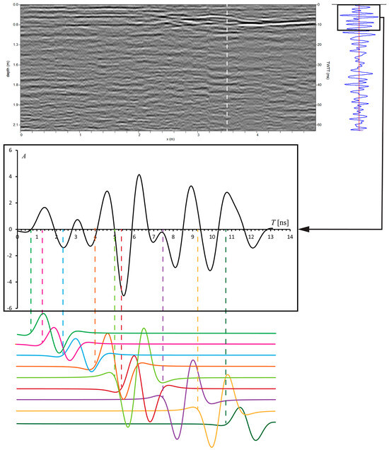
Figure 2.
Trace analysis and modelling. In this example, the first 13 ns of a radar profile trace (dashed line) are modelled by the superposition of nine Ricker wavelets with either positive or negative polarity and different amplitudes. The arrival times of these wavelets mark the location of as many reflectors, some of which could not be detected by visual analysis.
Figure 3 illustrates this possibility. It shows the interference of two wavelets with opposite (positive and negative) polarity and equal amplitude, associated with the top and bottom interfaces of a high-velocity layer, respectively. These wavelets, which have a first-zero crossing interval of ~2.5 ns and a breadth b of ~2.2 ns, can be used to model the pulses generated by a GSSI 400 MHz antenna.
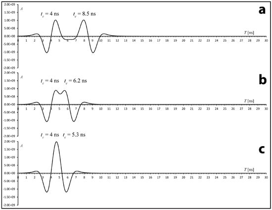
Figure 3.
An example of the composition between 90°-phase Ricker wavelets with opposite polarities. The horizontal axis shows two-way travel times. tc is the wavelet central time. (a) When the two wavelets are spaced by more than ~3 ns, their composition shows two distinct reflections. (b) If we increase the amount of overlap, a coalescent reflection forms, but we can still distinguish two positive peaks associated with the two component wavelets. (c) In the case of two strongly overlapped wavelets, a large amplitude peak forms, which could be erroneously interpreted as resulting from a single reflector separating two media characterized by a strong dielectric contrast. Instead, it results from wavelet interference.
When the difference in arrival times is comparable with the Rayleigh temporal resolution (b/2), a high-amplitude central peak forms (Figure 3c). On the trace of a radar profile, this peak may not be distinguishable from the positive peak of a single wavelet. In fact, the display of a radar profile requires translation from a 32-bit range of amplitude to a reduced number of colors, so that it may be difficult to discriminate the anomalous peak generated by constructive interference from a normal peak of high amplitude at the interface between two media with a strong dielectric contrast. Conversely, when a radar profile is analyzed by a forward modelling technique, the detection of a thin layer on selected traces is facilitated by the impossibility of obtaining a satisfactory fit between the observed and model traces. For example, it is not possible to model the signal in Figure 3c using a single 90°-phase Ricker wavelet. The ability to detect thin layers by forward modelling depends on the degree of uncertainty in the signal, because the modelling procedure stops when the difference between the model and observed traces falls below an assigned level of uncertainty at any depth. For example, if we decrease the difference in arrival times Δtc, the two wavelets in Figure 3 tend to be annihilated. Although perfect annihilation occurs only when Δtc = 0, we can assume that destructive interference takes place every time the wavelet composition has amplitudes that fall below the level of uncertainty of the signal. This means that we can never identify layers with a thickness so small that destructive interference takes place between the top and bottom reflections. Consequently, at least in principle, the annihilation limit can be used to measure the resolution of the trace analysis method. In this study, the detection of buried bones was performed using a GSSI 400 MHz antenna, whose pulse had a breadth of 2.2 ns. The resolution limit for this system, Δta, depends on the amplitude A of the two wavelets that are being annihilated and on the amount of uncertainty ε at their arrival time. Empirically, we obtain the following: . For example, for a relatively strong amplitude A = 1.0 × 10⁹ [counts] and an uncertainty ε = 1.64 × 10⁸ [counts], we would obtain Δta = 0.05 ns. This uncertainty is two orders of magnitude lower than the classic Rayleigh limit δz = λD/4 = vb/4, corresponding to ~1.1 ns in TWTT for the 400 MHz antenna. However, the quantity Δta = 0.05 ns represents only a theoretical limit that is largely exceeded by the resolution imposed by the data sampling time interval, which is given by the time range divided by the number of samples. In our case, this practical limit is ~0.14 ns, which is one order of magnitude smaller than the Rayleigh limit.
We consider now the parameters that control the spectrum and breadth (or first-zero crossing interval) of a modelling wavelet. Although it is possible to extract the amplitude spectrum of a wavelet using a statistical method that analyzes the amplitude spectrum of an observed trace [22], here we follow a more empirical approach based on forward modelling. In principle, the peak frequency fp that appears in Equation (1) should be assigned by considering the central frequency of the antenna. It is possible to prove that the frequency band of a Ricker wavelet can be calculated from fp by the following: fc ≈ 1.059095 fp, Δf ≈ 1.154944 fp; here, fc is the central frequency and Δf is the bandwidth [18,19]. Therefore, if the data have been acquired by a 400 MHz GPR, the wavelets generated by the transmitting antenna have a peak frequency fp ≈ fc/1.059095 ≅ 378 MHz. However, it is important to note that the reflected wavelets always have a breadth that is greater than the input pulse, independent of the reflection depth. This is in part a consequence of the bandpass filtering that is applied to the data [23]. To take into account this fact, we assign the central frequency fc in such a way that the model ground reflection pulse fits, in any case, the breadth of the first wavelet of a trace. Additionally, it is necessary to consider the frequency-dependent attenuation that affects the reflected wavelets, which is described by a quality factor Q* [24,25]. Such attenuation determines a shift in the peak of the amplitude spectrum (Equation (2)) of the wavelets that have propagated through the medium for a time interval t. This shift has been used by some authors to measure the factor Q* (e.g., [26]). Here, we use Q* as a modelling parameter, whose value is determined by fitting the breadth of a wavelet close to the trace base.
We assume that the frequency-dependent attenuation function can be expressed as follows [25,27]:
where v is the velocity of propagation, ε′ is the real part of the complex dielectric permittivity at frequency f, and μ is the magnetic permeability. Therefore, the amplitude spectrum of a Ricker wavelet that has traveled for a time t is given by the following:
where is given by Equation (2). If fp(t) is the peak frequency at time t, the partial derivative of function (6) with respect to f is zero when f = fp(t).
Therefore, we easily obtain the following:
Finally, solving this equation for fp(t) gives the following:
This is the peak frequency that is used to generate a Ricker wavelet at a two-way travel time (TWTT) t. Figure 4 shows the progressive shift in the amplitude spectrum as a function of TWTT, calculated using Equation (8), as well as the attenuation of the corresponding 90°-phase Ricker wavelets.
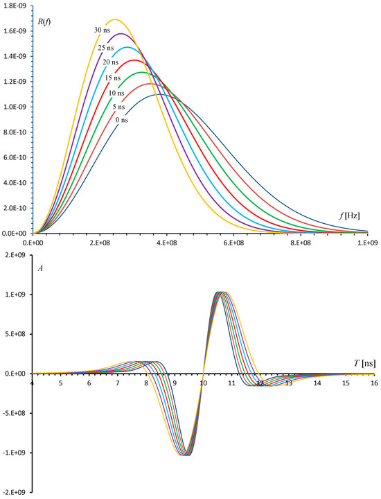
Figure 4.
Top: Shift and reduction in the amplitude spectrum bandwidth with time due to dispersion. A quality factor Q* = 20 is assumed. Both the peak and central frequencies are shifted to the left. Bottom: Corresponding dispersion of a 90°-phase Ricker wavelet in the time domain.
Let us consider now the problem of determining the uncertainty of the acquired data. As in any other forward modelling approach (e.g., in magnetic field modelling [28]), estimating the uncertainty of the observed data is necessary to obtain a threshold, and this is used to stop the trial-and-error fitting steps when the misfit between the observed and model trace falls below the estimated level of uncertainty. In the case of GPR data, the uncertainty has at least two distinct sources. There is an instrumental uncertainty, which is independent of the ground characteristics and can be estimated by a single experiment at an arbitrary location, and a spatial uncertainty that is related to the presence of small-scale disturbance at the air–ground interface. To estimate the instrumental uncertainty, we can perform an experiment at a fixed location through the acquisition of a single trace for a sufficiently long time interval.
Figure 5 illustrates the results of an experiment performed at a fixed location using a GSSI 400 MHz antenna in time-mode for 1200 s. The time evolution of the first positive and negative amplitude peaks of the acquired trace is shown in the top and bottom plots, respectively. The observed amplitudes of the first positive and negative peaks show a transient instrumental drift for ~600 s, followed by a stationary (in statistical sense) signal with pseudo-random oscillations about a steady value. To obtain an estimate of the uncertainty, we considered the mean and the standard deviation of each sample of the trace in the stationary range after 600 s. The resulting average scan is shown in Figure 6, along with the 1σ uncertainty. It is apparent in Figure 6 that this parameter increases linearly with the depth, and several other experiments at fixed locations confirmed this observation. Therefore, we applied this criterion for all the traces analyzed by forward modelling. In the following, the term ‘uncertainty’ always refers to a 2σ interval about the observed traces and includes both a depth-dependent instrumental component and a constant spatial uncertainty related to the presence of many small irregularities at the air–ground interface. The latter causes variations in the amplitude of the ground reflection that can be used to estimate this uncertainty component. In the case study presented below, we used the standard deviation of the average ground reflection amplitude recorded on 400 scans acquired along an 8-metre test line.
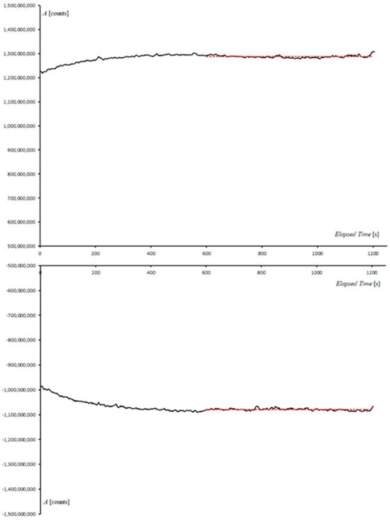
Figure 5.
Transient instrumental drift. The horizontal axis shows the elapsed time, while the vertical axis shows the observed peak amplitudes (in counts) after AGC gain, bandpass (200–600 MHz) filtering, and stacking (sliding window of width 7). The experiment shows that peaks below ~11 ns TWTT have an initial transient phase of ~600 s, characterized by instrumental drift, which is followed by a more stable phase of quasi-constant amplitude (red dashed lines).
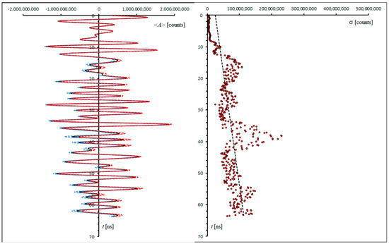
Figure 6.
Mean trace and 1σ instrumental uncertainty. Left: Time-averaged trace <A> (black line) in the stable range between 600 and 1200 s. The dashed red and blue lines show the upper and lower 1σ intervals, respectively. This is the same dataset as that in Figure 5. Right: Standard deviations of the mean trace amplitudes in the stable range between 600 and 1200 s (dots). The corresponding linear regression curve (black dashed line) is used in the forward modelling procedures as a depth-dependent estimate of the instrumental uncertainty.
4. Survey and Preprocessing Methods
4.1. GPR Data Acquisition and Pre-Processing
We tested the technique described above through the study of a partially buried baleen skeleton in the Ica Desert fossil-lagerstätte, at the top of the CLQ hill (Figure 1). The areas of GPR investigation are shown in Supplementary Materials Figure S3, the location of the fossil whale being within Area P4A (see Supplementary Materials Figure S4). GPR data were acquired using a GSSI SIR 4000 system equipped with 200 and 400 MHz antennas (see Supplementary Materials Figure S5). We used the following survey parameters (values separated by a slash refer to the 200 and 400 MHz antennas, respectively):
- Survey mode = Distance mode (with survey wheel)
- Scans/m = 50
- Samples/scan = 1024/512
- Range = 300/70 ns
- Bits/sample = 32
- Line spacing = 5 or 0.5/0.25 m
In the case of area P5, the survey lines were travelled in zig–zag mode (one direction), while areas P5A and P4A were surveyed in two orthogonal directions.
The pre-processing of the GPR data required the following steps (Supplementary Materials Figure S6):
- Automatic gain control (AGC)
- Time-zero correction
- Bandpass filtering
- Stacking
- Cepstrum deconvolution (only for amplitude slices)
- Kirchhoff migration (only for amplitude slices)
- Creation of amplitude slices
The bandpass cutoff frequencies were set to 100 and 300 MHz for the 200 MHz antenna, and to 200 and 600 MHz for the 400 MHz antenna. We applied boxcar horizontal stacking (7 traces) to reduce noise. The radar scans underwent forward modelling just after boxcar horizontal stacking to keep the data as close to raw data as possible. For the same reason, we did not apply background removal, which has a dramatic impact on amplitudes. Conversely, migration and the production of depth slices were preceded by the construction of a velocity profile and by cepstrum deconvolution. The amplitude slices were built by taking the average magnitude of the signal in bins of 0.95 ns with a 50% overlap between consecutive bins.
4.2. Aerial Photogrammetry
An aerial photogrammetry survey was performed at the top of CLQ using a DJI Mavic 2 Enterprise Dual N1869, equipped with an FC2403 camera (Supplementary Materials Figure S4). Owing to the autonomy of the drone, several photogrammetric flights were planned to cover the entire area, flying at ~34 m altitude and at ~5 m/s speed. The survey produced 1323 images that were acquired with a nadir view. The camera was set to its maximum resolution (12 Mpx) and had a focal length of 4.5 mm. With these parameters, the ground sample distance was 1.03 cm/pix. Before starting the flight, 34 control points and 14 check points were deployed and their location was acquired by a GPS receiver. Finally, the software Agisoft Metashape 1.6.4 was used to generate the DEM shown in Supplementary Materials Figure S7.
5. Results
We tested the technique described above through the study of a partially buried baleen skeleton (Figure 1). The areas of GPR investigation are shown in Supplementary Materials Figure S3, the location of the fossil whale being within Area P4A (see Supplementary Materials Figure S4). The general features of the near-surface radar stratigraphy at the top of the CLQ hill are illustrated in Figure 7, while amplitude slices for the large Area P5 are shown in Supplementary Materials Figure S8. The sedimentary succession is crossed by a series of small-offset normal faults (Figure 7a), which are generally accompanied by hanging-wall rotation. The cross-section in Figure 7 shows the presence of many point disturbances at ~2 m depth, which can be interpreted as dolomite nodules. The application of trace analysis (Figure 7b,c) suggests the presence of layers where the velocity progressively increases. We interpret these regions (yellow areas in Figure 7c) as being formed by low-dielectric diatomaceous sediments rich in biogenic SiO2 (εr ~ 4.5 [29,30]). Some sharp velocity increments in these beds are visible as strong reflectors on the radar profiles (e.g., reflectors X and Y in Figure 7a). The diatomaceous layers are interrupted by several thin high- or low-velocity beds whose top and bottom interfaces are marked by reflectivity spikes with opposite polarity (layers L1, L2, P, H1, and H2). Finally, the reflectivity plot in Figure 7c shows the presence of regions characterized by alternating increments and decrements in velocity about an almost constant value.
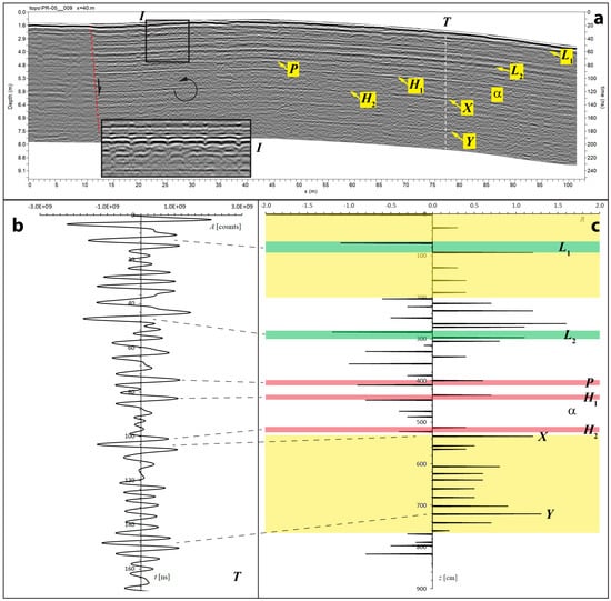
Figure 7.
Large-scale structures and radar stratigraphy at the top of CLQ (Area P5), as observed by a 200 MHz antenna. (a) Geological structures identified on a representative radar profile. The dashed red line is a small-offset normal fault that causes downward slip and the anticlockwise rotation of the layers to the right of the fault plane. Inset I shows an interval characterized by numerous dolomite nodules. T is a representative trace that has been analyzed by forward modelling. L1 and L2 are thin low-velocity layers, while H1 and H1 are thin encapsulated high-velocity layers. Correlation with a key marker bed outcropping at area P4A indicates that the ~20 cm thick layer P around a depth of 400 cm is the Perro horizon described by [13]. X and Y are two reflectors that bound zones with a strong increase in velocity. α is a region of decreasing velocity between H1 and H2, which can be observed in the radar profiles of area P4A (see below). (b) A model of trace T between zero and 170 ns. (c) A pseudo-reflectivity plot, showing wavelet arrivals, polarities, and scaled reflection amplitudes, and the associated geological interpretation. Green and reddish regions are encapsulated low- and high-velocity zones, respectively. Yellow regions are characterized by a general increase in velocity and can be interpreted as diatomaceous beds.
We assume that the relatively low-velocity beds correspond to the dolomite layers described by [16] (εr~7–8 [31]), while the presence of ultra-high velocity layers and skeleton components in materials whose dielectric constant does not exceed 7–8 requires some additional consideration.
For example, the high-velocity Perro key bed [13] that appears in the radar profile of Figure 7 is formed by partly cemented sediments that include anhydrite, quartz, goethite, gypsum, and illite [16]. All these mineral components, except goethite (εr~13–14 [32]), have dielectric constants that are between those of the diatomaceous sediments and dolomite, so that the strong velocity increase in this layer cannot be easily justified except by the combined effect of porosity and dry conditions. The general equation that relates the dielectric constant of a porous medium, εr, to the dielectric constants of the filling material and the rock component, respectively εf and εs, reads as follows [33]:
where p is the porosity. In the case of dry sediments, the first term on the right-hand side of this equation disappears (εf = 1) and we obtain the following:
As an example, for εs = 5 and p = 0.5, we would have εr = 2.2. Therefore, it is reasonable to assume that the presence of thin high-velocity layers and structures in the diatomaceous or dolomite sediments is associated with the entrapment of air in sediments that are only partially cemented or in the bones of buried skeletons.
The fossil whale skeleton that is partly exposed in the small 12 × 5 m area P4A (see Supplementary Materials Figure S4) was studied through a high-resolution GPR survey performed using a 400 MHz antenna (see above). The specimen was originally labelled CLQC-27 [34,35] and identified therein as belonging to Cetacea indet. What is currently exposed at the surface includes an articulated posterior segment of the vertebral column totaling more than 4 m in length. Anteriorly, the vertebral column disappears into the sediment, so that the skull bones should be found at a shallow depth below the surface (Supplementary Materials Figure S4a). The zone in which the skull remains may be preserved consists of a block of hardened sediment that could not be excavated for the purposes of the present study. Although no diagnostic (i.e., taxonomically informative) areas of the skeleton (e.g., the cranium) are exposed alongside the aforementioned vertebrae, the size of CLQC-27 is suggestive of a large-sized, baleen-bearing whale of the suborder Mysticeti. The presence of the whale modified the diagenetic processes of the surrounding sediments, so that it is useful to consider the undisturbed radar stratigraphy of Site P4A, far from the skeleton (Figure 8). A correlation with the profile in Figure 7, located ~170 m north of Site P4A, was obtained on the basis of direct dip and strike measurements [13] and the geometry of the Perro key bed, which crosses Site P4A (Figure 8). This correlation suggests that the sedimentary succession at Site P4A includes, from top to bottom, (a) part of the high-velocity layer H1, (b) the decreasing velocity bed α, (c) the high-velocity layer H2, and (d) part of the diatomaceous succession below reflector X. The amplitude slices at Site P4A are illustrated in Figure 9. They show the presence of a very reflective interval between 2.5 and 3.4 ns (Figure 9b), corresponding to the positive peak of the inverted polarity wavelet reflected at a 20 cm depth (Figure 8). Presumably, this is the base of layer H1, which appears to be interrupted by a non-reflective region where the whale experienced rapid self-burial and formed a scour depression [34]. At a TWTT higher than ~6 ns and up to ~14 ns (corresponding to ~1 m depth), the only reflective regions are those associated with the presence of the whale skeleton and its Fe and Mn oxide envelope (Figure 9c,d). The procedure used to identify the skeletal components on the radar profiles acquired at Site P4A is illustrated in Figure 10, Figure 11 and Figure 12. The presence of bones is always revealed by prominent amplitude peaks in the traces, which result in part from constructive interference between the top and bottom reflections of thin structures (see Figure 3c) and, to some extent, from dielectric contrasts. The fossil bones at Site P4A appear as high-velocity intervals, especially relative to the underlying sediments.
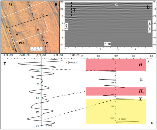
Figure 8.
Radar stratigraphy of Area P4A, as observed by a 400 MHz antenna. (a) Survey geometry at area P4A on a background DEM image. W is the outcropping part of the vertebral column, N is a surface bulge just above the dolomite nodule, P is the Perro key bed. (b) A radar profile (at x = 0) not affected by the presence of the buried skeleton. T is a representative trace (at x = 1 m). (c) A model of trace T (left) and the corresponding pseudo-reflectivity plot (right). The latter shows wavelet arrivals, polarities, and scaled reflection amplitudes. α is the decreasing velocity region of Figure 7, while H1 and H2 are high-velocity beds. Correlation lines (black dashed lines) link the reflectivity peaks to wavelet centers, not to arrival times.
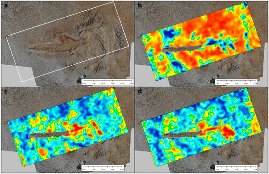
Figure 9.
Amplitude slices at site P4A. (a) Orthomosaic of area P4A after partial excavation and cleaning. The brown envelope around the skeleton is associated with the presence of iron oxides. The dolomite nodule above and around the whale skull is also evident. (b) Reflection amplitudes between 2.5 and 3.4 ns. Blue and red regions have low and high reflectivity, respectively. (c) Reflection amplitudes between 6.7 and 7.6 ns. (d) Reflection amplitudes between 9.5 and 10.5 ns.
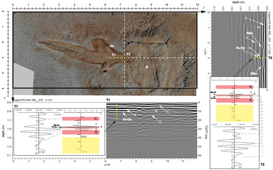
Figure 10.
Identification of vertebrae and ribs on the radar profiles of the fossil whale at site P4A. The background image shows an orthomosaic of the whale after partial excavation and cleaning. Fe-Ox = Iron oxide layer; Mn-Ox = Manganese oxide layer; Ox = Iron and manganese oxide envelope around the whale skeleton; N = dolomite nodule; V = vertebral column. The modelling of traces T1 and T2 shows the signature of the vertebral column and some ribs. In these profiles, vertebrae and ribs are embedded in the layer α. Bones are detected as thin structures, bounded by strong reflectivity peaks of opposite polarity.
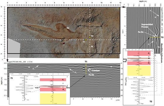
Figure 11.
Identification of the cranium and mandibles on the radar profiles of the fossil whale at site P4A. C = cranium; SP = supraorbital process; other symbols are the same as in Figure 10.
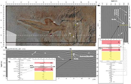
Figure 12.
Identification of rostrum and mandible on the radar profiles of the fossil whale at site P4A. R-M = rostrum/mandible; other symbols are the same as Figure 10.
In fact, while the reflectivity peak at the upper interface can be either very strong or just noticeable, the lower reflection is always strong. When both reflection peaks have a large amplitude (see Figure 11), this is most likely a consequence of air being entrapped in the pores and cavities of the buried bones [34]. Several studies have shown that many exceptionally preserved vertebrate fossils of the Pisco Basin are embedded in hard dolomite nodules [36]. These concretions may be more than 10 cm thick and are in contact with the fossil bones. The transition zone of the surrounding undisturbed sediments is formed by a non-laminated yellow layer with abundant authigenic apatite, followed by a very thin (<1 cm) black layer permeated by Mn oxide, which formed below the sediment–water interface at a redox boundary during the decomposition of the carcass [15,37].
A reddish sediment with a matrix rich in Fe oxides or hydroxides completes the sequence [36]. This assemblage of yellow–black–red (YBR) sediments has a thickness between a few centimeters and a few decimeters. In the case of the specimen at Site P4A, partial excavation has shown the presence of a dolomite nodule around the neurocranium (Figure 10, Figure 11 and Figure 12), while there is no evidence of carbonate concretion surrounding the rest of the skeleton. On the basis of these observations, we would expect the reflection peaks associated with the presence of bones to be closely followed by additional reflections due to the thin Mn-rich and Fe-rich layers. The presence of these layers is also evident in Figure 10, Figure 11 and Figure 12, where they appear to surround the whale carcass. The dielectric constant of manganese oxides is very high, at around 60–70 according to [32], so that the black layer should be observed as a low-velocity interval. However, field observations show that while the inner interface of this bed, close to the bones, is sharp, the bottom part gradually transitions to the sediments rich in Fe oxides [37]. Consequently, the base of the Mn-rich layer and top of the underlying Fe-rich bed were not visible on the radar profiles. The trace analysis performed on representative scans of the radar profiles acquired at site P4A shows that, in most cases, the thin manganese layer is very close to the bones along the bottom side of the skeleton. The correlation between the reflectivity plots in Figure 8, Figure 10, Figure 11 and Figure 12 (see the Supplementary Materials) suggests that the general signature of fossil specimens in this area is a triplet of strong spikes in the sequence: positive–negative–positive (+–+) polarity. In this series, the central negative spike combines the two reflections of equal polarity produced at the lower interface of a bone and at the top of the Mn-rich layer (see Wavelet Packets in the Supplementary Materials). However, in some cases, the black layer has sufficient thickness and separation from the bones to be visible as an independent doublet (e.g., see Figure 11).
The first-order skeletal anatomy of a modern Mysticeti whale is shown in Supplementary Materials Figure S9. Figure 10 shows the radar profiles and traces that cross the buried part of the vertebral column in two orthogonal directions. The y-oriented profile 18 shows that the vertebral column terminates with a small depression, detected as a bow-tie structure on the radar profile. Such a depression probably hosts the cranium, which appears to be oriented in the x direction, just like the dolomite nodule. In the x-oriented profile 74, it is possible to note the presence of a pair of hyperbolae flanking the vertebral column, which can be reasonably interpreted as ribs. The skeletal components embedded in the dolomite nodule are considered in Figure 11 and Figure 12. The y-oriented profile 20 (Figure 11) shows the continuation of the depression observed in Figure 10 in the x direction. Trace T1 in this profile is one of the few scans where it is possible to observe an independent low-velocity reflectivity doublet that can be associated with the very thin Mn-rich layer. This trace is centered on the cranial vertex. On the transverse profile 80, trace T2 suggests the presence of a thicker interval with the same signature, which could be generated by a supraorbital process in an inclined position with respect to the ground surface. If this interpretation is correct, the segment of the radar profile after 3.7 m would be produced by the mandibles and rostrum. A transverse section of these two skeletal components is visible on profile 22 (Figure 12). This profile also provides a transversal view of the dolomite nodule around the skeleton. Finally, the more distal profile 82 (Figure 12) shows an evident hyperbola with the typical bone signature, which is most likely produced by a detached bone, possibly a cervical vertebra.
6. Discussion
This paper describes a new technique for detecting vertebrate skeletons and other thin features buried shallowly underground by GPR. In this approach, a target is always a 3D object vertically bounded by a couple of reflectors (top and bottom) and characterized by an observable contrast of dielectric permittivity with respect to the surrounding material. Therefore, individual reflectors that mark discontinuities in the electric properties of the ground are not considered targets for the present study, although they can be mapped in geological interpretations. To be observable, a dielectric contrast must produce a wavelet with an amplitude greater than the background noise. However, when the thickness of a target falls below the Rayleigh resolution limit, the top and bottom reflections merge into a single high-amplitude pulse (as in Figure 3), or they might even annihilate each other. The technique presented above allows one to reduce the minimum thickness of a detectable object below the Rayleigh resolution, depending on the ambient noise, but with a theoretical limit given only by the time step between consecutive samples (i.e., time range/samples per trace). For this purpose, we stress that the vertical resolution values given by the Rayleigh or Ricker criteria were proposed in the 1950s as practical resolvability limits for the correct manual selection of arrival times in the analysis of noise-free seismic profiles [8]. Nowadays, the use of computers and forward modelling allows researchers to assign the arrival times of two close wavelets with great accuracy and reproduce any interference peak. This method provides a higher resolution, limited only by the data uncertainty. Figure 13 illustrates an example of the kind of reconstruction that can be achieved by the correlation of the reflectivity plots generated through trace analysis. This reconstruction reveals details about the geometry of subsurface structures that cannot be easily achieved by the visual inspection of a radar profile. In addition to this, it provides information about the electric properties of the layers and features in the ground.
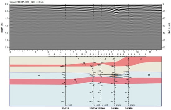
Figure 13.
A reconstruction of the underground between depths of 0 and 130 cm along a cross-section at x = 3.5 m in Area P4A. This reconstruction shows the lateral extent of the high-velocity layers H1 and H2 and the geometry of the depression below the whale head. The small high-contrast brown, blue, and orange regions between x = 8.1 and 8.6 m represent the cranium and the underlying Mn and Fe oxides.
Another example of the results that can be obtained by the method described above is illustrated in Figure 14. These data were acquired at Dinosaur Ridge, Colorado, in 2018 by L. Conyers and his team using a 900 MHz antenna. This site is known for the presence of numerous dinosaur footprints. The reconstruction in Figure 14 illustrates the advantage of using trace analysis for radar profile interpretation. The presence of a dinosaur footprint is not very evident in the profile in Figure 14, because several strong reflections in the right part, not related to the presence of dinosaur remains or their passage, tend to overwhelm the important signals associated with the plantar pressure pattern and the underlying sub-track consolidation [38]. Conversely, the reconstruction obtained by the correlation of several trace analysis reflectivity plots shows a clear pattern that can be interpreted as being due to a dinosaur footprint.
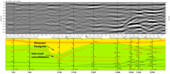
Figure 14.
Identification of dinosaur footprints on a radar profile (top) acquired at Dinosaur Ridge (CO) (data courtesy of L. Conyers). Yellow = sandstone; light green = mudstone. Orange and dark green areas are high- and low-velocity regions, respectively.
The procedure described in the previous sections can be applied to data acquired with any GPR antenna, even to very-low-frequency bistatic antennas in geological applications. This technique assumes that GPR traces can be reconstructed by the superposition of Ricker wavelets with an assigned phase (90° in the present study). Since the 1950s, Ricker wavelets have been known as appropriate models of radiating pulses in exploration seismology [8], especially thanks to their propagation invariance [39]. These wavelets have been also widely used in GPR research to fit the amplitude spectra of real GPR data (see [25] and references therein). The reconstruction of a GPR trace by a linear combination of Ricker wavelets can be accomplished either by inverse or forward modelling. The former represents the traditional approach, based on time-frequency decomposition [40,41]. The latter is proposed for the first time in this paper and involves a trial-and-error manual procedure for fitting wavelets to the observed trace below an assigned uncertainty level. In general, the output of the inversion methods is represented by sharp radar images with improved resolution (see e.g., [41]). In the case of trace analysis, the main goal is to detect thin targets that could not be resolved by the visual inspection of radar profiles, and create tomographic maps that show the presence of regions with anomalous electromagnetic properties, embedded in nearly homogeneous layers. An important difference in our approach compared to inversion procedures is that we assume a constant quality factor Q*, representing the average attenuation in the background material. As mentioned above, this quantity is estimated by fitting a model wavelet close to the base of the considered time window, whereas in inversion procedures, Q* can change with depth and is a result of the inversion itself.
Trace analysis requires that radar data processing be accomplished with very limited distortion of the waveforms. For example, background removal, migration, and cepstrum deconvolution lead to substantial modifications of the frequency band and produce an unpredictable bias in the radar profiles. Consequently, radar data should not undergo these processing procedures before trace analysis is undertaken. This limits the applicability of the method in some cases. For example, wet, heterogeneous soils lead to a strong impedance mismatch between the antenna and feed cable, which results in a ringdown noise that reduces the resolution and contaminates the radar profile with horizontal bands [42]. In this instance, a possible strategy consists of the application of an advanced method of background removal, such as the double-sided sliding paraboloid (DSSP) algorithm [43], the eigenimage filtering method [44], or the non-linear data processing approach of Chen and Jeng [45]. In the case study presented above, the ground characteristics did not require such additional pre-processing. As for the multiples, their presence should always be checked in the reflectivity plots obtained by trace analysis. This task can be accomplished through the following procedure. Let t1, t2, …, tn be the arrival times of the n Ricker wavelets that form a model trace. There is an uncertainty ±δtk on these times, which can be determined during the forward modelling procedure by changing the arrival time tk until the error (observed signal minus model) rises above the background uncertainty (see the Supplementary Materials, A_Short_Guide_To_Trace_Analysis_and_Modelling_by_Microsoft_Excel.pdf). If, for any pair of indices j and k, it results that |tk − 2tj|< δtk and the two reflectors can be followed for the whole profile, then it is possible to suppress the spike at t = tk in the reflectivity plot. A similar method can be applied to other kinds of multiple reflections.
Another potential source of error arises from the application of gain, particularly the method known as automatic gain control (AGC) [46]. However, any kind of gain produces only a minimum change in the relative amplitudes in a time window that includes several wavelets. Furthermore, gain procedures do not change the zeroes of the trace. It is also important to stress that, for the present study, the absolute amplitudes of the wavelets are less important than their polarities.
Microsoft Excel templates for the forward modelling of radar traces can be found in the Supplementary Materials. The application of this method to the individuation of large vertebrate fossils, buried at a shallow depth in the Ica Desert, seems promising and depends on the fact that, in most cases, the bones form a characteristic sequence of thin layers that generate strong reflectivity peaks. Conversely, the normalized correlation chart between the reflectivity plots in Figure 8, Figure 10, Figure 11 and Figure 12 (see the Supplementary Materials) indicates that bones may not have a strong dielectric contrast with respect to the embedding materials. Forward modelling suggests that this is not a limitation, as the combined effect of dielectric contrasts and constructive interferences produces, in all cases, characteristic wave packets with a strong amplitude that are easily identified by trace analysis (see Wavelet Packets in the Supplementary Materials). Therefore, we are confident that the proposed technique can be effective in discovering buried specimens in the specific environmental conditions of the Ica Desert.
It is reasonable to ask whether the technique can also be applied in other fossil-lagerstätten and fossil-rich sites to detect buried skeletons of vertebrates, for example, in the Mongolian Gobi Desert. A technique similar to the one presented above was used at the beginning of the new millennium to search for dinosaur bones at the Dinosaur Ridge site mentioned above [47]. In that study, the bones were mineralized by iron oxide, mainly in the form of goethite, with a dielectric permittivity much higher than the surrounding sandstone of the Morrison Formation. In more recent years, GPR methods have been rarely used in the search for fossils, and the interpretation of radar data has been based in any case on specific filtering (e.g., [48]) or imaging techniques [49]. We know that the possibility of detecting the presence of fossil bones through GPR depends on (1) the electromagnetic properties of the surrounding material, particularly its conductivity and magnetic permeability, and (2) the mode and degree of bone mineralization, including the impregnation of the bone pores and cavities. In the case of fossilized whales, the latter process acquires an even greater importance because of the very high porosity of their bones [50]. The diagenetic processes that occur during vertebrate fossilization involve the early transformation of the mineralized internal skeleton, composed of hydroxylapatite, into a more compact phase formed by secondary fluorapatite via the substitution of elements in the original “bioapatite” lattice [51]. This transformation results in an increased crystallite size and a consequent reduction in porosity [37,52]. Late diagenetic alteration includes the further recrystallization of apatite and the precipitation of secondary minerals, such as apatite, dolomite, quartz, gypsum, iron or manganese oxides, which partially or totally fill the bone cavities [34,52]. This permineralization of the bone pores and cavities is critical in determining the final dielectric permittivity of the fossil bones and the possibility of detecting buried skeletons by GPR. For example, an abundant concentration of gypsum (εr ≅ 2.37 [53]) and the presence of air (εr = 1) in the cavities would yield a quite low average dielectric constant for the bones, despite the intermediate value of fluorapatite (εr = 9–10 [54]). This is possibly the case for the specimen from Site P4A, where the bones are detected as high-velocity structures. Conversely, late mineralization by iron-bearing minerals like hematite (εr ~ 19) would result in a rather high degree of dielectric contrast with respect to the surrounding sediment made of sandstone. In this instance, a skeleton would be detected as a low-velocity structure. The presence of an iron and manganese oxide envelope helps the individuation of buried fossils.
A final remark concerns the relationship between the reflectivity plots and the velocities that can be estimated by fitting radar profile hyperbolas. In fact, a reflectivity plot puts a strong constraint on the variations in the velocity of the propagation of the signal with depth, v = v(t), because the amplitude and polarity of a reflectivity peak depend on the variation in dielectric permittivity across an interface between two media. It is clear that the sign of velocity variations on a reflectivity plot should be coherent with the changes in the mean velocity observed independently on reflection hyperbolas during the migration procedure. We built a velocity profile for each survey area, which was representative of the general layering of the underground in terms of electric properties. For this purpose, it is important to note that the velocity values , estimated at depths where a hyperbola is available, represent the rms velocities between the surface and a hyperbola apex, whose location does not generally coincide with the interface between layers with different electric properties. In fact, hyperbolas are in most cases generated by anomalous bodies embedded in a homogeneous material. Therefore, the procedure of hyperbola fitting was followed by the construction of the spline regression curve of the observed rms velocities , which was used to estimate the rms velocity at the base of each layer. The TWTT location of reflectors separating layers with different electric properties was constrained by the reflectivity plots obtained by the forward modelling of representative traces. For example, in the case of area P4A, we used the arrival times of the synthetic trace in Figure 8 to assign a TWTT tk to the base of each layer, so that is an estimate of the rms velocity at the base of the layer.
The pairs were used, with the Dix formula [55], to calculate the true velocity of each layer in the model and to convert the TWTTs to depths. Figure 15 shows the results of this analysis for area P4A. This procedure not only allows one to perform a better TWTT–depth conversion, in so far as it allows one to create a model of the ground velocity layering, but also ensures that the reflectivity plots that are built independently by trace analysis are compatible with the velocity profiles observed during migration.

Figure 15.
Velocity analysis of area P4A. (a) Spline regression of the rms velocities obtained by hyperbola fitting (black line). Red dots are the observed rms velocities (by the migration procedure). The blue line shows the laterally homogeneous velocity profile, based on Dix’s equation. The numbers refer to layer numbering. (b) Reflectivity plot for area P4A, in terms of TWTT.
7. Conclusions
The results presented in the previous sections, which are based on a new technique of trace analysis and modelling for GPR data, show that the method is effective in detecting buried vertebrate skeletons in paleontological research. The application of this technique to the study of a partially buried fossil skeleton of a large whale in the Ica Desert fossil-lagerstätte of Peru has been successful in characterizing some skeletal components. In a more general context, the reflectivity plots resulting from trace analysis can reveal the presence of thin intervals bounded by reflectors of opposite polarity, associated with layers with a higher or lower velocity than the surrounding material. Sometimes these intervals result from very subtle features that represent interesting survey targets, e.g., small cracks, thin lenses of liquid contaminants, etc., which could be confused with individual reflectors through the simple visual inspection of a radar profile. Therefore, our quantitative approach can be used in many other applications of GPR methods, particularly in forensic, civil engineering, heritage protection, and soil stratigraphy applications. Reflectivity plots can also be used to perform reconstructions of the subsurface via the correlation of reflectivity peaks on different traces. This technique allows one to obtain more constrained interpretations compared to the classic visual inspection of radar profiles.
Supplementary Materials
The following supporting information can be downloaded at: https://www.mdpi.com/article/10.3390/rs16203858/s1, Schettino_et_al_(2024)_Supplementary_Figures.pdf: Supplementary Figures S1–S9; Correlation_Chart.pdf: Correlation chart between traces; Wavelet_Packets.pdf: Characteristic wave packets associated with bones; A_Short_Guide_To_Trace_Analysis_and_Modelling_by_Microsoft_Excel.pdf: User’s manual for the Microsoft Excel modelling software; Ricker-Modelling_400MHz_18_33.xlsx, Ricker-Modelling_200MHz_9_3899.xlsx, Ricker-Modelling_900MHz_1-140.xlsx: Microsoft Excel template files for trace modelling; Profiles.zip: Radar profiles of Area P4A.
Author Contributions
A.S. conceived the trace analysis modelling and planned the field experiments, A.S. and A.G. conducted the experiments, analyzed and interpreted the data, and performed trace modelling, P.P.P. and A.C. participated in the data acquisition, A.C. reviewed the paleontological interpretation of the GPR data, L.T. contributed to data analysis and modelling, C.D.C. supervised and coordinated the project. All authors reviewed the manuscript. All authors have read and agreed to the published version of the manuscript.
Funding
This research was funded by the Università degli Studi di Camerino (grant FAR 2019 to Di Celma) and the European Union–NextGenerationEU, Mission 4, Component 2 CUP I53D23002070 006.
Data Availability Statement
Dataset available on request from the authors.
Acknowledgments
We would like to thank four anonymous reviewers and the editors for their comments, which improved significantly the manuscript. We thank the headmaster of the ITTS Divini of San Severino Marche, Sandro Luciani, for his support of A. Ghezzi. We are also grateful to Walter Aguirre and his colleagues at the Departamento de Paleontología de Vertebrados, Museo de Historia Natural of Lima, Peru, who helped us in the data acquisition stage. Finally, we thank Flavio Travasso for his support in the design of a parallel plate capacitor for the measurement of the dielectric constants.
Conflicts of Interest
The authors declare no conflicts of interest. The funders had no role in the design of the study; in the collection, analyses, or interpretation of data; in the writing of the manuscript; or in the decision to publish the results.
References
- Conyers, L.B. Ground-penetrating radar mapping using multiple processing and interpretation methods. Remote Sens. 2016, 8, 562. [Google Scholar] [CrossRef]
- Millington, T.M.; Cassidy, N.J.; Nuzzo, L.; Crocco, L.; Soldovieri, F.; Pringle, J.K. Interpreting complex, three-dimensional, near-surface GPR surveys: An integrated modelling and inversion approach. Near Surf. Geophys. 2011, 9, 297–304. [Google Scholar] [CrossRef]
- Bianucci, G.; Collareta, A. An overview of the fossil record of cetaceans from the East Pisco Basin (Peru). Boll. Soc. Paleontol. Ital. 2022, 61, 19–20. [Google Scholar]
- Sheriff, R.E.; Geldart, L.P. Exploration Seismology, 2nd ed.; Cambridge University Press: Cambridge, UK, 1995; 573p. [Google Scholar]
- Bristow, C.S.; Jol, H.M. Ground Penetrating Radar in Sediments; Geological Society of London: London, UK, 2003; 330p. [Google Scholar]
- Kallweit, R.S.; Wood, L.C. The limits of resolution of zero-phase wavelets. Geophysics 1982, 47, 1035–1046. [Google Scholar] [CrossRef]
- Huggenberger, P. Radar facies: Recognition of facies patterns and heterogeneities within Pleistocene Rhine gravels, NE Switzerland. Geol. Soc. Lond. Spec. Publ. 1993, 75, 163–176. [Google Scholar] [CrossRef]
- Ricker, N. Wavelet contraction, wavelet expansion, and the control of seismic resolution. Geophysics 1953, 18, 769–792. [Google Scholar] [CrossRef]
- Widess, M.B. How thin is a thin bed? Geophysics 1973, 38, 1176–1180. [Google Scholar] [CrossRef]
- van Dam, R.L.; van Den Berg, E.H.; Schaap, M.G.; Broekema, L.H.; Schlager, W. Radar reflections from sedimentary structures in the vadose zone. Geol. Soc. Lond. Spec. Publ. 2003, 211, 257–273. [Google Scholar] [CrossRef]
- Guha, S.; Kruse, S.E.; Wright, E.E.; Kruse, U.E. Spectral analysis of ground penetrating radar response to thin sedimentary layers. Geophys. Res. Lett. 2005, 32, L23304. [Google Scholar] [CrossRef]
- Bianucci, G.; Di Celma, C.; Collareta, A.; Landini, W.; Post, K.; Tinelli, C.; de Muizon, C.; Bosio, G.; Gariboldi, K.; Gioncada, A.; et al. Fossil marine vertebrates of Cerro Los Quesos: Distribution of cetaceans, seals, crocodiles, seabirds, sharks, and bony fish in a late Miocene locality of the Pisco Basin, Peru. J. Maps 2016, 12, 1037–1046. [Google Scholar] [CrossRef]
- Di Celma, C.; Malinverno, E.; Cantalamessa, G.; Gioncada, A.; Bosio, G.; Villa, I.M.; Gariboldi, K.; Rustichelli, A.; Pierantoni, P.P.; Landini, W.; et al. Stratigraphic framework of the late Miocene Pisco Formation at Cerro los Quesos (Ica desert, Peru). J. Maps 2016, 12, 1020–1028. [Google Scholar] [CrossRef]
- Bosio, G.; Malinverno, E.; Villa, I.M.; Di Celma, C.; Gariboldi, K.; Gioncada, A.; Barberini, V.; Urbina, M.; Bianucci, G. Tephrochronology and chronostratigraphy of the Miocene Chilcatay and Pisco formations (East Pisco Basin, Peru). Newsl. Stratigr. 2020, 53, 213–247. [Google Scholar] [CrossRef]
- Gariboldi, K.; Pike, J.; Malinverno, E.; Di Celma, C.; Gioncada, A.; Bianucci, G. Paleoceanographic implications of diatom seasonal laminations in the Upper Miocene Pisco Formation (Ica desert, Peru) and their clues on the development of the Pisco Fossil-Lagerstätte. Paleoceanogr. Paleoclimatol. 2023, 38, e2022PA004566. [Google Scholar] [CrossRef]
- Malinverno, E.; Bosio, G.; Gioncada, A.; Cimò, R.; Andò, S.; Mariani, L.; Coletti, G.; Boschi, C.; Gariboldi, K.; Galimberti, L.; et al. Laterally-continuous dolomite layers of the Miocene Pisco Formation (East Pisco Basin, Peru): A window into past cyclical changes of the diagenetic environment. Mar. Pet. Geol. 2023, 147, 105977. [Google Scholar] [CrossRef]
- Bianucci, G.; Marx, F.G.; Collareta, A.; Di Stefano, A.; Landini, W.; Morigi, C.; Varola, A. Rise of the titans: Baleen whales became giants earlier than thought. Biol. Lett. 2019, 15, 20190175. [Google Scholar] [CrossRef]
- Wang, Y. The Ricker wavelet and the Lambert W function. Geophys. J. Int. 2015, 200, 111–115. [Google Scholar] [CrossRef]
- Wang, Y. Frequencies of the Ricker wavelet. Geophysics 2015, 80, A31–A37. [Google Scholar] [CrossRef]
- Zeng, H.; Backus, M.M. Interpretive advantages of 90°-phase wavelets: Part 1—Modeling. Geophysics 2005, 70, C7–C15. [Google Scholar] [CrossRef]
- Arcone, S.A.; Spikes, V.B.; Hamilton, G.S. Phase structure of radar stratigraphic horizons within Antarctic firn. Ann. Glaciol. 2005, 41, 10–16. [Google Scholar] [CrossRef]
- Gao, J.; Zhang, B.; Han, W.; Peng, J.; Xu, Z. A new approach for extracting the amplitude spectrum of the seismic wavelet from the seismic traces. Inverse Probl. 2017, 33, 085005. [Google Scholar] [CrossRef]
- Lash, C.C. A note on “Aspects of vertical seismic resolution” by O. Koefoed. Geophys. Prospect. 1982, 30, 515–518. [Google Scholar] [CrossRef]
- Bradford, J.H. Frequency-dependent attenuation analysis of ground-penetrating radar data. Geophysics 2007, 72, J7–J16. [Google Scholar] [CrossRef]
- Economou, N.; Kritikakis, G. Attenuation analysis of real GPR wavelets: The equivalent amplitude spectrum (EAS). J. Appl. Geophys. 2016, 126, 13–26. [Google Scholar] [CrossRef]
- Quan, Y.; Harris, J.M. Seismic attenuation tomography using the frequency shift method. Geophysics 1997, 62, 895–905. [Google Scholar] [CrossRef]
- Bano, M. Modelling of GPR waves for lossy media obeying a complex power law of frequency for dielectric permittivity. Geophys. Prospect. 2004, 52, 11–26. [Google Scholar] [CrossRef]
- Schettino, A.; Ghezzi, A.; Pierantoni, P.P. Magnetic field modelling and analysis of uncertainty in archaeological geophysics. Archaeol. Prospect. 2019, 26, 137–153. [Google Scholar] [CrossRef]
- Howell, B.F., Jr.; Licastro, P.H. Dielectric behavior of rocks and minerals. Am. Mineral. 1961, 46, 269–288. [Google Scholar]
- Bottom, V.E. Dielectric constants of quartz. J. Appl. Phys. 1972, 43, 1493. [Google Scholar] [CrossRef]
- Apel, D.B.; Dezelic, V. Evaluation of high frequency ground penetrating radar (GPR) in mapping strata of dolomite and limestone rocks for ripping technique. Int. J. Surf. Min. Reclam. Environ. 2005, 19, 260–275. [Google Scholar] [CrossRef]
- Nelson, S.; Lindroth, D.; Blake, R. Dielectric properties of selected and purified minerals at 1 to 22 GHz. J. Microw. Power Electromagn. Energy 1989, 24, 213–220. [Google Scholar] [CrossRef]
- Baklanov, M.R.; Maex, K. Porous low dielectric constant materials for microelectronics. Philos. Trans. R. Soc. A 2006, 364, 201–215. [Google Scholar] [CrossRef]
- Bosio, G.; Collareta, A.; Di Celma, C.; Lambert, O.; Marx, F.G.; de Muizon, C.; Gioncada, A.; Gariboldi, K.; Malinverno, E.; Malca, R.V.; et al. Taphonomy of marine vertebrates of the Pisco Formation (Miocene, Peru): Insights into the origin of an outstanding Fossil-Lagerstätte. PLoS ONE 2021, 16, e0254395. [Google Scholar] [CrossRef]
- Collareta, A.; Lambert, O.; Marx, F.G.; de Muizon, C.; Malca, R.V.; Landini, W.; Bosio, G.; Malinverno, E.; Gariboldi, K.; Gioncada, A.; et al. Vertebrate Palaeoecology of the Pisco Formation (Miocene, Peru): Glimpses into the ancient Humboldt Current ecosystem. J. Mar. Sci. Eng. 2021, 9, 1188. [Google Scholar] [CrossRef]
- Gariboldi, K.; Gioncada, A.; Bosio, G.; Malinverno, E.; Di Celma, C.; Tinelli, C.; Cantalamessa, G.; Landini, W.; Urbina, M.; Bianucci, G. The dolomite nodules enclosing fossil marine vertebrates in the East Pisco Basin, Peru: Field and petrographic insights into the Lagerstätte formation. Palaeogeogr. Palaeoclimatol. Palaeoecol. 2015, 438, 81–95. [Google Scholar] [CrossRef]
- Gioncada, A.; Gariboldi, K.; Collareta, A.; Di Celma, C.; Bosio, G.; Malinverno, E.; Lambert, O.; Pike, J.; Urbina, M.; Bianucci, G. Looking for the key to preservation of fossil marine vertebrates in the Pisco Formation of Peru: New insight from a small dolphin skeleton. Andean Geol. 2018, 45, 379–398. [Google Scholar] [CrossRef]
- Urban, T.M.; Bennett, M.R.; Bustos, D.; Manning, S.W.; Reynolds, S.C.; Belvedere, M.; Odess, D.; Santucci, V.L. 3-D radar imaging unlocks the untapped behavioral and biomechanical archive of Pleistocene ghost tracks. Sci. Rep. 2019, 9, 16470. [Google Scholar] [CrossRef]
- Gholamy, A.; Kreinovich, V. Why Ricker wavelets are successful in processing seismic data: Towards a theoretical explanation. In Proceedings of the IEEE Symposium on Computational Intelligence for Engineering Solutions CIES 2014, Orlando, FL, USA, 9–12 December 2014. [Google Scholar]
- Liu, J.; Wu, Y.; Han, D.; Li, X. Time-frequency decomposition based on Ricker wavelet. In SEG Technical Program Expanded Abstracts 2004; Society of Exploration Geophysicists: Houston, TX, USA, 2004; pp. 1937–1940. [Google Scholar]
- Zhang, X.; Liu, C.; Feng, X.; Li, B.; Li, K.; You, Q. The attenuated Ricker wavelet basis for seismic trace decomposition and attenuation analysis. Geophys. Prospect. 2020, 68, 371–381. [Google Scholar] [CrossRef]
- Radzevicius, S.J.; Guy, E.D.; Daniels, J.J. Pitfalls in GPR data interpretation: Differentiating stratigraphy and buried objects from periodic antenna and target effects. Geophys. Res. Lett. 2000, 27, 3393–3396. [Google Scholar] [CrossRef]
- Rashed, M.; Rashed, E.A. Double-Sided Sliding-Paraboloid (DSSP): A new tool for preprocessing GPR data. Comput. Geosci. 2017, 102, 12–21. [Google Scholar] [CrossRef]
- Kim, J.-H.; Cho, S.-J.; Yi, M.-J. Removal of ringing noise in GPR data by signal processing. Geosci. J. 2007, 11, 75–81. [Google Scholar] [CrossRef]
- Chen, C.-S.; Jeng, Y. Nonlinear data processing method for the signal enhancement of GPR data. J. Appl. Geophys. 2011, 75, 113–123. [Google Scholar] [CrossRef]
- Dondurur, D. Acquisition and Processing of Marine Seismic Data; Elsevier: Amsterdam, The Netherlands, 2018; 598p. [Google Scholar]
- Meglich, T.M. Use of ground penetrating radar in detecting fossilized dinosaur bones. In Proceedings of the Eighth International Conference on Ground Penetrating Radar, Gold Coast, Australia, 27 April 2000; Volume 4084, pp. 536–541. [Google Scholar]
- Ercoli, M.; Bizzarri, R.; Baldanza, A.; Bertinelli, A.; Mercantili, D.; Pauselli, C. GPR Detection of Fossil Structures in Conductive Media Supported by FDTD Modelling and Attributes Analysis: An Example from Early Pleistocene Marine Clay at Bargiano Site (Central Italy). Geosciences 2021, 11, 386. [Google Scholar] [CrossRef]
- Leucci, G. A ground penetrating test to detect vertebrate fossils. Archaeology 2013, 2, 28–37. [Google Scholar]
- Wysokowski, M.; Zaslansky, P.; Ehrlich, H. Macrobiomineralogy: Insights and enigmas in giant whale bones and perspectives for bioinspired materials science. ACS Biomater. Sci. Eng. 2020, 6, 5357–5367. [Google Scholar] [CrossRef]
- Keenan, S.W. From bone to fossil: A review of the diagenesis of bioapatite. Am. Mineral. 2016, 101, 1943–1951. [Google Scholar] [CrossRef]
- Bosio, G.; Gioncada, A.; Gariboldi, K.; Bonaccorsi, E.; Collareta, A.; Pasero, M.; Di Celma, C.; Malinverno, E.; Urbina, M.; Bianucci, G. Mineralogical and geochemical characterization of fossil bones from a Miocene marine Konservat-Lagerstätte. J. S. Am. Earth Sci. 2021, 105, 102924. [Google Scholar] [CrossRef]
- Giacomazzi, L.; Scandolo, S. Gypsum under pressure: A first-principles study. Phys. Rev. B 2010, 81, 064103. [Google Scholar] [CrossRef]
- Shannon, R.D.; Rossman, G.R. Dielectric constants of apatite, epidote, vesuvianite, and zoisite, and the oxide additivity rule. Phys. Chem. Miner. 1992, 19, 157–165. [Google Scholar] [CrossRef]
- Tillard, S.; Dubois, J.C. Analysis of GPR data: Wave propagation velocity determination. J. Appl. Geophys. 1995, 33, 77–91. [Google Scholar] [CrossRef]
Disclaimer/Publisher’s Note: The statements, opinions and data contained in all publications are solely those of the individual author(s) and contributor(s) and not of MDPI and/or the editor(s). MDPI and/or the editor(s) disclaim responsibility for any injury to people or property resulting from any ideas, methods, instructions or products referred to in the content. |
© 2024 by the authors. Licensee MDPI, Basel, Switzerland. This article is an open access article distributed under the terms and conditions of the Creative Commons Attribution (CC BY) license (https://creativecommons.org/licenses/by/4.0/).