Abstract
The Direction of Arrival (DOA) parameter is a key parameter in directional channel modeling for GNSS systems and multipath suppression. However, achieving high-precision, low-complexity DOA estimation of multiple signal sources without requiring a known source number is still a challenge. This paper introduces a satellite navigation DOA parameter estimation method based on deconvolution beamforming. By exploiting the translational invariance property of the uniform linear array pattern, the deconvolution process is applied to the de-spread array pattern of satellite navigation signals, achieving high-precision estimation of DOA parameters. This method can achieve high-precision blind DOA estimation of multiple signal sources while significantly reducing the estimation complexity. Compared with traditional methods, precise DOA estimation can be achieved even in low-signal-to-noise-ratio conditions and with a small number of elements in the array. The theoretical analysis and simulation results verify the effectiveness of the proposed algorithm.
1. Introduction
Global Navigation Satellite Systems (GNSS) can provide high-precision navigation, positioning, and timing services, and they have been widely applied [1,2] in fields such as civil aviation, autonomous driving, precision agriculture, and the military, inter alia. However, multipath errors have become some of the most severe threats constraining the precision and robustness of navigation positioning [3].
Accurate estimation of the Direction of Arrival (DOA) parameters of GNSS signals is crucial for modeling multipath channels, assessing multipath effects, and mitigating multipath influences. DOA estimation methods have drawn broad research interest due to their wide applications in fields such as navigation, sonar, radar, and communications [4]. The methods for DOA estimation have been extensively studied and can be broadly categorized into the following groups:
Spectral estimation methods [5], e.g., Maximum Likelihood Estimation (MLE) [6] and the Capon Algorithm [7], which estimate signal source directions by minimizing output energy in interference directions. However, their performance decreases in low-signal-to-noise-ratio (SNR) conditions and is sensitive to noise and array errors.
Matrix eigenspace decomposition, e.g., Multiple Signal Classification (MUSIC) [8] and Estimating Signal Parameter via Rotational Invariance Techniques (ESPRITs) [9], exploits the statistical properties of signals to estimate DOA through eigen decomposition. These methods can overcome the resolution limitations of traditional beamforming but require prior knowledge of the number of signal sources and a high level of model accuracy in practical applications.
Compressive sensing methods, e.g., Orthogonal Matching Pursuit (OMP) [10] and the Sparse Bayesian Learning method [11], utilize the sparse nature of signals to reconstruct sparse signals through optimization algorithms for DOA estimation. These methods can achieve accurate DOA estimation at lower sampling rates but are sensitive to signal sparsity representation and the choice of optimization algorithms.
DOA estimation methods based on deep learning [12,13,14], e.g., Convolutional Neural Networks (CNN) [15] and Recurrent Neural Networks (RNN) [16], estimate DOA by learning signal features from large datasets. However, these methods require extensive training data and computational resources.
The Direction Lock Loop (DiLL) method [17,18] leverages the symmetrical properties of array pattern diagrams to stabilize DOA parameter tracking through loop design, significantly reducing computation, and it is applied in GNSS signal DOA estimation. However, this method requires coarse estimation information of DOA parameters and has limited resolution, making it difficult to distinguish multiple nearby signal sources.
To address these limitations, a DOA parameter estimation method based on deconvolved conventional beamforming is proposed. Firstly, a conventional array pattern is constructed in the correlation domain. The array pattern has translation invariance and can be equivalent to the convolution of the basis function and the impulse response function of the signal incident direction. Then, the deconvolution method is used to estimate the precise DOA parameters of the signal sources. The processing frequency of the proposed method is the same as the loop update frequency of the GNSS receiver, typically in the order of milliseconds, making it suitable for both static and dynamic scenarios. However, it cannot be used concurrently with array interference suppression beamforming techniques. This is primarily because such techniques can cause distortions in the array beam pattern, which may lead to inaccurate estimations.
The contributions of the proposed method are listed as follows: (1) it can achieve accurate blind estimation of multiple signal sources without requiring a known number of targets; (2) matrix inversion is not necessary, resulting in significantly lower computational complexity; (3) precise DOA estimation can be achieved even in low-signal-to-noise-ratio conditions and with a small number of elements in the array.
2. Signal Model
2.1. Multipath Signal Model
The navigation signals transmitted by GNSS satellites are received by receivers after propagating through space. Due to potential signal reflections from obstacles around the receiver, as illustrated in Figure 1, a received navigation signal includes both direct and reflected signals. These reflected signals are commonly known as multipath signals, which will introduce pseudo-range errors. Typically, multipath errors may be about 5–6 m for BPSK signal modulation and are reduced to about 1 m for AltBOC modulation [19].
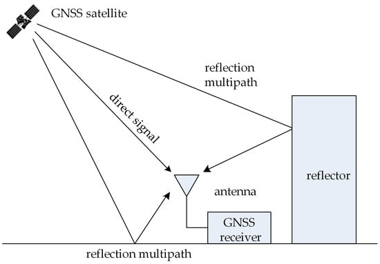
Figure 1.
Multipath reflection model with one antenna.
When satellite signals propagate to the ground, the received signal at the receiver is a combination of the direct signal component and the multipath component. Assuming that the received navigation signal includes a direct signal and multipath signals, the baseband signal after down-conversion can be represented as follows [20]:
where represents the signal amplitude; represents the pseudocode; represents the Doppler frequency; denotes the direct signal; and represent the multipath signal components. , , and represent the reflection coefficient, the time delay, and the carrier phase of the multipath signal component relative to the direct signal. indicates the direct signal. Clearly, . To simplify the analysis, the amplitude, time delay, and phase parameters are considered as constants within the time period under consideration.
Suppose the signal is in a tracking state, the Doppler frequency can be accurately estimated, and the local replica signal can be represented as follows [21]:
where represents the carrier phase estimation value and represents the received signal’s pseudocode delay estimation value.
The accumulated correlation value between the input signal and the locally generated replica can be expressed as follows [21]:
where represents the autocorrelation function of the GNSS signal and and indicate the code phase error and the carrier phase error of the component, respectively.
Reflected multipath signals undergo delays, phase shifts, and fading, in contrast to direct signals. To begin with, let us consider the case of a direct signal and one multipath signal. When the direct and multipath signals are in phase (), the sum of their amplitudes is greater than that of any individual component. Conversely, when the direct and multipath signals are out of phase (), the amplitudes of the two components will attenuate. A schematic diagram of the composite correlation peak is shown in Figure 2.
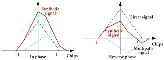
Figure 2.
The peak of direct signal and multipath signal correlation.
2.2. Signal Model Based on Array Antennas
The distance of the GNSS signal to the array antenna is much larger than the array aperture, and the far-field condition is satisfied. The wavefront of a GNSS signal can be approximated as a plane wave. Suppose that one line-of-sight signal component and multipath signal components impinge on a uniform linear array consisting of elements with element spacing . The baseband satellite navigation signal received by the array antenna can be represented as follows [5]:
where stands for the array data vector. The output of the nth element at time is represented by , while denotes the additive white Gaussian noise vector. It is commonly assumed that the observation noise on different array elements and at different time instants is mutually independent. represents the signal component.
where represents the array guide vector corresponding to the navigation signal, which can be expressed as
where is the signal incident angle, is the wavelength, and is the array spacing. A schematic diagram of the uniform linear array is shown in Figure 3.
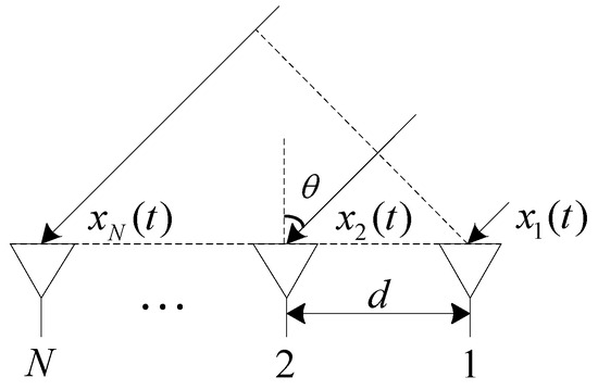
Figure 3.
Array configuration of uniform linear array.
The cumulative correlation value vector obtained by correlating the baseband array signals with the local replica signal can be represented as follows:
where indicates the accumulated time.
3. The Proposed Method
3.1. Conventional Beamforming
For any angle, , constructing an array weighting vector, , and multiplying it with the correlation value vector, the array output can be represented as follows:
where and . denotes the conjugate transpose. For the signal component, the peak of the beamforming energy spectrum occurs at point with a maximum output energy of . The position of the peak point will vary in accordance with the alteration in the incidence angle of the multipath signal.
For the signal component, the peak of the beamforming energy spectrum occurs at point with a maximum output energy of . Therefore, the maximum value of the beamforming energy spectrum can be utilized for estimating the DOA parameter of the signal. Figure 4 presents normalized beam patterns using the conventional beamforming method under various numbers of array elements, where indicates the number of array elements. It is evident from Figure 4 that the resolution of the beam pattern using the conventional beamforming method is heavily influenced by the physical size of the array; the greater the number of array elements, the narrower the main lobe width of the beam pattern. When the number of array elements is limited, traditional beamforming methods may not be adequate for DOA estimation. In this paper, we leverage the translational invariance property of the energy spectrum of the beam pattern to achieve high-precision DOA estimation through deconvolution techniques.
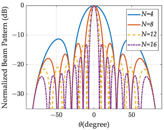
Figure 4.
Normalized beam patterns using conventional beamforming method with different numbers of array elements.
3.2. Deconvolved Conventional Beamforming
Rewrite the array beam pattern, , in Equation (8) as a function of .
where represents the sinc function.
The complex form of the beam pattern can be represented in the following convolution form.
where represents the point spread function and represents the magnitude distribution of the signal sources. represents the angular variable in the convolution operation, which satisfies the condition that varies continuously within the range of −1 to 1.
The array pattern can be expressed as the convolution of the pattern and the signal distribution spectrum [22]. Therefore, estimation of the signal source distribution can be achieved using deconvolution methods. However, deconvolution using the beam pattern, , can lead to an ill-posed problem. To solve this problem, deconvolution utilizes the beam energy spectrum instead of the complex beam.
The energy spectrum of the beam pattern can also be represented in a convolution form as follows.
where and the signal power distribution is represented by .
The Richardson–Lucy method [23] is a commonly used deconvolution technique that has been widely applied in the field of image processing for image deblurring, producing good results. In this study, we applied this method for deconvolution processing.
If the signal can be expressed in the following convolution form:
where represents the channel impulse response (CIR) and represents the signal source, the R-L method can be utilized for deconvolution processing to estimate . In this paper, denotes the spatial distribution of both the direct and multipath signals.
The R-L algorithm is an iterative method and can be expressed as follows:
where and represents the number of iterations.
In order to achieve estimation using the R-L algorithm, it is essential to ensure that the beam pattern exhibits translational invariance in the angular domain, denoted as . We can observe from Equation (11) that the point spread function exhibits translational invariance characteristics when expressed as a function of , while it does not exhibit translational invariance when expressed as a function of angle, .
Figure 5 illustrates the results of the array beam pattern. The array beam pattern was generated by employing the procedure outlined in Equation (8), through which the angle, , is scanned from −90 degrees to 90 degrees. Figure 5a presents a comparison of the conventional beamforming (CB) pattern and the deconvolved conventional beamforming (DCB) pattern, showing that the DCB method significantly enhances angular resolution. Figure 5b displays the DCB patterns obtained under different numbers of array elements, demonstrating that even with fewer array elements, very narrow spatial spectral estimation results can still be achieved.
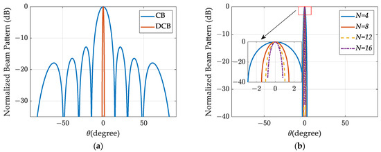
Figure 5.
Super-directional beam pattern: (a) the comparison of CB and DCB; (b) the comparison of DCB under different numbers of array elements.
The spatial spectrum plots in Figure 6 showcase the performance of various DOA estimation methods, including Capon, MUSIC, and the proposed method. Figure 6a displays the spatial spectrum results under single-signal-source conditions with an incident angle of −2.96° and a carrier-to-noise ratio () of 45 dBHz. Figure 6b presents the spatial spectrum results under conditions with one direct signal and one multipath signal, where the incident angles for the direct and multipath signals are −2.96° and 3.06°, respectively. It can be observed that even in the presence of two signal sources, the DCB method maintains good resolution capabilities, while the MUSIC and Capon methods fail to resolve the directions towards the signal sources.
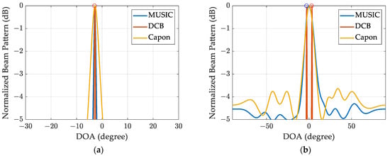
Figure 6.
Spatial spectrum estimation results with different DOA estimation methods (the circles represent the true DOA parameters): (a) estimation results under the condition of only a single direct signal; (b) estimation results under the condition of one direct signal and one multipath signal.
3.3. The Implementation Process of the Method
The implementation process of this method is shown in Figure 7.
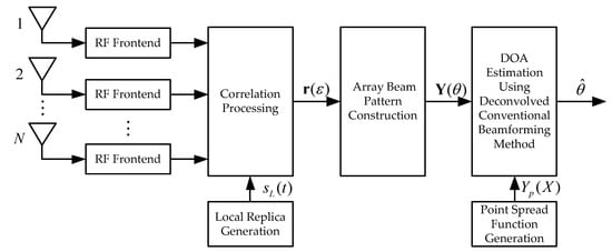
Figure 7.
Block diagram of the proposed method.
(1) The received array signal is processed by the RF front-end module. After low-noise amplification, filtering, down-conversion, and sampling, the RF signal converts to the baseband signal, .
(2) Generate the local replica signal, , for de-spreading the array signal.
(3) Compute the correlation value vector, , by multiplying the replica with the array signal.
(4) Generate the array beam pattern, , by employing the procedure outlined in Equation (8), through which the angle, , is scanned from −90 degrees to 90 degrees.
(5) Generate the point spread function, .
(6) Estimate the DOA parameters using the deconvolved conventional beamforming method.
4. Results
The simulation parameters were as follows: a GPS L1 C/A signal was simulated, the code frequency was 1.023 Mbps, the signal sampling rate was 6 MHz, and the coherent integration time was 1 ms. The performance of the proposed method was verified using Monte Carlo simulation with 1000 iterations. The DOA estimation performance was evaluated using the Root Mean Square Error (RMSE), which is defined as follows:
where represents the estimated angle of the signal in the Monte Carlo simulation, while denotes the number of Monte Carlo simulation iterations.
The performance of the proposed method was compared with Capon, MUSIC, and OMP.
4.1. The Performance of DOA Estimation for a Single Signal Source
Initially, we examined the method’s performance under the condition of only a direct signal with different signal-to-noise ratios, array sizes, and incident-angle conditions.
Figure 8 presents the RMSE results for different input signals, , and array sizes, with increasing from 30 dBHz to 50 dBHz. Figure 8a–d illustrate the results for scenarios , respectively. The results show a significant improvement in DOA estimation accuracy with increasing . When is low, the performance of the OMP method is slightly better than that of the proposed method, and both of them are significantly better than MUSIC and Capon. As increases, the DCB method can achieve a similar performance to OMP. Moreover, higher array sizes lead to greater estimation accuracy. The proposed method consistently outperforms the other methods, validating its effectiveness. Even under low-signal-to-noise-ratio conditions, satisfactory estimation results can still be achieved.
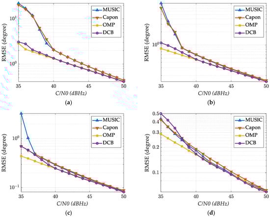
Figure 8.
Statistical results of DOA estimation under different ratios: (a) N = 4; (b) N = 8; (c) N = 12; (d) N = 16.
In Figure 9, the DOA estimation results are presented for varying incident angles within the range of [−60, 60]. Figure 9a,b show the estimation errors when the number of array elements is N = 8 and N = 12, respectively. It can be seen from Figure 9 that the estimation error increases with the increase in the incident angle, and the greater the number of array elements, the smaller the estimation error. The performance of the proposed method and the OMP method is better than that of the MUSIC method and the Capon method.
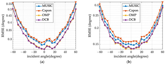
Figure 9.
Statistical results of performance estimation for different incident angles: (a) N = 8; (b) N = 12.
4.2. The Performance of DOA Estimation for Multiple Signal Sources
Simulations were conducted for a scenario involving a line-of-sight signal and a multipath signal. Figure 10 illustrates the DOA estimation performance under varied conditions. The incident angles for the line-of-sight and multipath signals are −8.98 degrees and 9.06 degrees, respectively. The amplitude attenuation coefficient for the multipath signal is 0.5, and the relative time delay of the multipath signal compared to the line-of-sight signal is 0.5 chips. When N = 8, the DOA estimation performance of the proposed method is the best, which indicates that a better spatial resolution can be achieved when the number of array elements is small. When N = 12, this method can achieve similar performance to OMP.
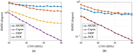
Figure 10.
Estimation statistic results under different ratios: (a) N = 8; (b) N = 12.
5. Conclusions
DOA estimation is essential for GNSS channel modeling, assessing multipath effects, and mitigating multipath errors. In order to achieve high-precision blind estimation of multiple signal components with low computational complexity, this study introduces a super-directive beamforming-based DOA estimation method. Firstly, the correlation value vector is generated by multiplying the array signal with a locally replicated signal. Secondly, the array response pattern is formulated within the correlation domain, which is tantamount to the convolution of the fundamental function with the impulse response function of signal incident directions. Thirdly, leveraging the principles of deconvolution, precise estimation of DOA parameters is accomplished using the Richardson–Lucy algorithm. This paper further substantiates the proposed method’s performance in scenarios involving both single and multiple signal sources. When there is only one signal source and the ratio is greater than 40 dBHz, the proposed method can achieve similar performance to OMP. When there are multiple targets and the number of array elements is small, such as when , the new method significantly outperforms the OMP algorithm. In both cases, the proposed method significantly outperforms the MUSIC and Capon methods. The findings indicate that, compared to traditional approaches, our method delivers superior estimation accuracy under low signal-to-noise ratios and with a limited number of array elements, without the need for prior knowledge of the signal source number. The experimental results validate the rationality and effectiveness of the proposed method, making it suitable for integration into compact, low-power GNSS array antenna systems for precise real-time DOA parameter estimation. Additionally, it has the potential for wider application in DOA estimation within the realms of communication, radar, and other related fields.
Author Contributions
Conceptualization, J.W., F.W., and X.T.; methodology, J.W., X.T., and C.L.; software, J.W., H.L., and C.L.; validation, J.W. and X.T.; formal analysis, J.W. and H.L.; investigation, J.W.; resources, J.W.; data curation, J.W.; writing—original draft preparation, J.W.; writing—review and editing, C.L., H.L., and X.T.; visualization, J.W.; supervision, F.W.; project administration, X.T.; funding acquisition, F.W. and J.W. All authors have read and agreed to the published version of the manuscript.
Funding
This research was funded by the National Natural Science Foundation of China, grant number U20A0193, and the National Natural Science Foundation of China, grant number 62303482.
Data Availability Statement
The original contributions presented in the study are included in the article, further inquiries can be directed to the corresponding author.
Conflicts of Interest
The authors declare no conflicts of interest.
Correction Statement
This article has been republished with a minor correction to resolve spelling and grammatical errors, the image quality of Figure 1 and the readability of Figures 4–6 and 8–10. These changes do not affect the scientific content of the article.
References
- Gao, W.G.; Zhou, W.; Tang, C.P.; Li, X.X.; Yuan, Y.Q.; Hu, X.G. High-precision services of BeiDou navigation satellite system (BDS): Current state, achievements, and future directions. Satell. Navig. 2024, 5, 20. [Google Scholar] [CrossRef]
- Lu, J.; Guo, X.; Su, C.G. Global capabilities of BeiDou Navigation Satellite System. Satell. Navig. 2020, 1, 27. [Google Scholar] [CrossRef]
- Qiu, W.Q.; Zeng, Q.H.; Xu, R.; Liu, J.Y.; Shi, J.H.; Meng, Q. A multipath mitigation algorithm for GNSS signals based on the steepest descent approach. Satell. Navig. 2022, 3, 14. [Google Scholar] [CrossRef]
- Johnson, D.H.; Dudgeon, D.E. Array Signal Processing: Concepts and Techniques; Simon Schuster: New York, NY, USA, 1992. [Google Scholar]
- Fernandez-Prades, C.; Arribas, J.; Closas, P. Robust GNSS Receivers by Array Signal Processing: Theory and Implementation. Proc. IEEE 2016, 104, 1207–1220. [Google Scholar] [CrossRef]
- Georgiou, P.G.; Kyriakakis, C. Maximum likelihood parameter estimation under impulsive conditions, a sub-Gaussian signal approach. Signal Process. 2006, 86, 3061–3075. [Google Scholar] [CrossRef]
- Capon, J. High-resolution frequency-wavenumber spectrum analysis. Proc. IEEE 1969, 57, 1408–1418. [Google Scholar] [CrossRef]
- Zhao, B.; Yang, Y.; Wang, Z.; Liu, X.; Peng, M.; Jin, Y. Barycenter Calibration of Spatial Spectra for Direction-of-Arrival Estimations Based on Capon/MUSIC Algorithms. IEEE Wirel. Commun. Lett. 2023, 12, 2068–2072. [Google Scholar] [CrossRef]
- Zhang, W.; Han, Y.; Jin, M.; Li, X.-S. An Improved ESPRIT-Like Algorithm for Coherent Signals DOA Estimation. IEEE Commun. Lett. 2020, 24, 339–343. [Google Scholar] [CrossRef]
- Weiland, L.; Wiese, T.; Utschick, W. Multipath Mitigation Using OMP and Newton’s Method for Multi-Antenna GNSS Receivers. In Proceedings of the 2017 IEEE 7th IEEE International Workshop on CAMSAP, Curacao, The Netherlands, 10–13 December 2017. [Google Scholar]
- Zheng, R.; Xu, X.; Ye, Z.; Dai, J. Robust sparse Bayesian learning for DOA estimation in impulsive noise environments. Signal Processing 2020, 171, 107500. [Google Scholar] [CrossRef]
- Ge, S.G.; Li, K.; Rum, S. Deep Learning Approach in DOA Estimation: A Systematic Literature Review. Mob. Inf. Syst. 2021, 2021, 6392875. [Google Scholar] [CrossRef]
- Huang, H.; Yang, J.; Huang, H.; Song, Y.; Gui, G. Deep Learning for Super-Resolution Channel Estimation and DOA Estimation Based Massive MIMO System. IEEE Trans. Veh. Technol. 2018, 67, 8549–8560. [Google Scholar] [CrossRef]
- Naseri, M.; Shahid, A.; Gordebeke, G.J.; Lemey, S.; Boes, M.; Van De Velde, S.; De Poorter, E. Machine Learning-Based Angle of Arrival Estimation for Ultra-Wide Band Radios. IEEE Commun. Lett. 2022, 26, 1273–1277. [Google Scholar] [CrossRef]
- Chen, D.; Joo, Y.H. Multisource DOA Estimation in Impulsive Noise Environments Using Convolutional Neural Networks. Int. J. Antennas Propag. 2022, 2022, 5325076. [Google Scholar] [CrossRef]
- Tian, Q.; Cai, R.Y.; Luo, Y.; Qiu, G.R. DOA Estimation: LSTM and CNN Learning Algorithms. Circuits Syst. Signal Process. 2024. [Google Scholar] [CrossRef]
- Min, S.; Seo, D.; Lee, K.B.; Kwon, H.M.; Lee, Y.H. Direction-of-arrival tracking scheme for DS/CDMA systems: Direction lock loop. IEEE Trans. Wirel. Commun. 2004, 3, 191–202. [Google Scholar] [CrossRef]
- Wu, J.; Tang, X.; Huang, L.; Ni, S.; Wang, F. Blind Adaptive Beamforming for a Global Navigation Satellite System Array Receiver Based on Direction Lock Loop. Remote Sens. 2023, 15, 3387. [Google Scholar] [CrossRef]
- Padokhin, A.M.; Mylnikova, A.A.; Yasyukevich, Y.V.; Morozov, Y.V.; Kurbatov, G.A.; Vesnin, A.M. Galileo E5 AltBOC Signals: Application for Single-Frequency Total Electron Content Estimations. Remote Sens. 2021, 13, 3973. [Google Scholar] [CrossRef]
- Kai, B.; Akos, D.; Bertelsen, N.; Rinder, P.; Jensen, S. A Softwaredefined GPS and Galileo Receiver: A Single-Frequency Approach; Springer: New York, NY, USA, 2007. [Google Scholar]
- Enge, P.K. The Global Positioning System: Signals, measurements, and performance. Int. J. Wirel. Inf. Netw. 1994, 1, 83–105. [Google Scholar] [CrossRef]
- Yang, T.C. Deconvolved Conventional Beamforming for a Horizontal Line Array. IEEE J. Ocean. Eng. 2018, 43, 160–172. [Google Scholar] [CrossRef]
- Chen, L.; Zhang, J.; Li, Z.; Wei, Y.; Fang, F.; Ren, J.; Pan, J. Deep Richardson-Lucy Deconvolution for Low-Light Image Deblurring. Int. J. Comput. Vis. 2024, 132, 428–445. [Google Scholar] [CrossRef]
Disclaimer/Publisher’s Note: The statements, opinions and data contained in all publications are solely those of the individual author(s) and contributor(s) and not of MDPI and/or the editor(s). MDPI and/or the editor(s) disclaim responsibility for any injury to people or property resulting from any ideas, methods, instructions or products referred to in the content. |
© 2024 by the authors. Licensee MDPI, Basel, Switzerland. This article is an open access article distributed under the terms and conditions of the Creative Commons Attribution (CC BY) license (https://creativecommons.org/licenses/by/4.0/).