Abstract
Adaptive antenna arrays are widely used to protect Global Navigation Satellite System (GNSS) receivers from interference. However, conventional blind anti-jamming array processing methods can cause satellite signal attenuation, which reduces signal tracking precision and measurement accuracy. To alleviate this problem, this paper proposes the noncoherent channel combining method for GNSS signal tracking with an adaptive antenna array. A two-stage processing architecture is applied in the proposed method, where the first stage implements interference suppression, and the second stage achieves noncoherent channel combining. The proposed method has the advantage of blind characteristics that can be implemented without any other auxiliary information. It also reveals a unified processing architecture for anti-jamming array processing methods. Thus, a detailed comparison and analysis of the proposed method with several typical blind anti-jamming methods is performed. Simulation results demonstrate the effectiveness of the proposed method and its superiority over existing methods in terms of tracking performance.
1. Introduction
Recently, position, navigation, and timing (PNT) information has become increasingly important to our modern society [1]. The Global Navigation Satellite System (GNSS) has been widely used to provide PNT information due to its easy availability. Unfortunately, the GNSS signal is extremely weak, making it vulnerable to both intentional and unintentional interference [2]. Therefore, it is of great importance to mitigate the effects of interference to keep GNSS receivers operating continuously.
The adaptive antenna array with anti-jamming array processing techniques is the state-of-the-art approach to interference suppression [3]. The minimum variance distortionless response (MVDR) algorithm [4] is one of the most popular techniques. It can not only suppress interference but also maximize the signal-to-noise ratio (SNR). However, the implementation of the MVDR algorithm requires prior knowledge of the satellite steering vector. This increases the complexity of the implementation and also limits the application during cold start of the GNSS receiver.
Blind anti-jamming array processing techniques, such as the power inversion (PI) algorithm [5], can adaptively suppress the interference without any prior knowledge. This type of technique is more attractive in practical engineering due to its ease of implementation and wide range of applications. However, the PI algorithm cannot provide an array gain for the satellite signal, and it often results in satellite signal attenuation [6]. This reduces the signal tracking precision and thus degrades the measurement accuracy. To address this issue, many other blind algorithms have been studied.
The direction-of-arrival (DOA) estimation methods can be used to extract the spatial information of the satellite signal for beamforming [7]. To reduce the complexity of DOA estimation, the angle-locked loop has been proposed to achieve closed-loop angle tracking [8]. However, this type of approach requires accurate knowledge of the array manifold, which is not easily determined without costly array calibration [9]. This is because the antenna array and its associated electronics are subject to many errors, some of which are even environment-dependent [10]. Moreover, the performance of angle estimation or tracking is degraded in coherent signal environments, such as the multipath environment. The spectral self-coherence restoral technique has been proposed in the literature [11,12]. It can form high-gain beams toward the satellites by using the repetitive feature of the GNSS code without requiring the knowledge of the satellite direction. However, this technique cannot mitigate the interference that has similar self-coherence properties to the GNSS signal, such as the continuous wave interference. The beamforming algorithm in [13,14] reconstructed the spatial signature vector of the satellite signal using the carrier phase measurements obtained from the tracking channel of each antenna. However, it is not suitable in an interference scenario because signal tracking will fail in this case. The minimum mean square error (MMSE) algorithm [15] is known to use the waveform information of the reference signal for beamforming. However, the reference signal should be obtained by the receiver tracking loop, so it inevitably contains estimation errors that degrade the performance of the algorithm.
Different from the above approaches, this paper considers the adaptive antenna array from the perspective of a multichannel system. Then, a new method for GNSS signal tracking using adaptive antenna arrays is proposed based on the concept of channel combining. The main contributions of this work are summarized as follows:
- (1)
- Conventional anti-jamming methods are explained as a unified two-stage processing architecture, where the first stage is interference suppression and the second stage is channel combining.
- (2)
- Noncoherent channel combining is studied for GNSS signal tracking with an adaptive antenna array to improve signal tracking precision and measurement accuracy after interference suppression.
- (3)
- A thorough comparison and analysis of the proposed method with several representative blind anti-jamming techniques is performed to show its superiority over conventional methods.
2. Mathematical Model
This section introduces the signal model for antenna arrays and anti-jamming methods using array weighting.
2.1. Signal Model
Without loss of generality, assuming that one GNSS signal is received by an N-element antenna array as well as Q interfering signals, the received signal vector can be expressed, using the complex intermediate frequency (IF) representation, as
where is the GNSS signal, with being the corresponding steering vector, is the qth interfering signal, and is the corresponding steering vector. is the additive noise vector, the elements of which are independent and have a complex Gaussian distribution with zero mean and variance . Moreover, the GNSS signal, interfering signals, and noise are assumed independent of each other.
The IF received GNSS signal in Equation (1) can be formulated as
where P is the signal power, is the navigation data bit, is the pseudo-random noise code, is the time delay, is the IF, is the Doppler frequency, and is the initial carrier phase. The interfering signals are assumed to be much stronger than the GNSS signal, such that the spreading spectrum signal gain is not sufficient to maintain the reception of the GNSS signal.
2.2. Array Weighting
To suppress the strong interference, a weight vector is applied to the received signal vector in Equation (1) as
where denotes the conjugate transpose operation.
The weight vector can be obtained based on different criteria. The MVDR algorithm is well known in various fields with the following cost function
where denotes the auto-correlation matrix of the received signal vector, and denotes the expectation operation. The solution is given by
where denotes the matrix inversion operation.
The MVDR algorithm can not only steer nulls in the jammer directions but also maximizes the gain in the satellite direction with the unity constraint. However, it needs to know the satellite steering vector, which requires the DOA of the GNSS signal and the array configuration, increasing the complexity of the system. Suppressing the interference without this kind of prior knowledge is more attractive.
The PI algorithm is one possible choice, using the following cost function
where is a constraint vector, and denotes the transpose operation. The solution is expressed as
The PI algorithm is widely used in practical engineering since it can suppress the strong interference from any direction without any prior knowledge. The PI algorithm is more cost effective than the MVDR algorithm, but it may attenuate the satellite signal, which affects the signal tracking precision.
3. Proposed Method
This section presents the proposed method, which adopts a two-stage processing architecture, where interference suppression is the first stage and channel combining is the second stage. The details are presented in the following subsections.
3.1. Interference Suppression
This subsection implements interference suppression based on the subspace projection technique.
The GNSS signal is much weaker than the noise, while the interference is assumed to be much stronger. Therefore, can be separated into auto-correlation matrices of the interference and noise, and , as follows [16]
where denotes the power of the qth jammer, and stands for the identity matrix. The eigenvalue decomposition of is given by
where and represent the nth eigenvalue and the associated orthonormal eigenvector of , respectively. In the case of strong interference, the eigenvalues can be arranged in nonincreasing order:
From Equations (8) and (11), it can be seen that the eigenvectors corresponding to the largest eigenvalues span the interference subspace, i.e., . Therefore, Equation (12) becomes
where is the orthogonal complementary space of the interference.
By projecting the received signal vector into , the interference can be effectively mitigated. The projection can be expressed as
where is the projected signal vector. Here, is used to replace to avoid eigenvalue decomposition and thus reduce computational complexity. The interference can be effectively suppressed by projecting the signal vector into the interference-free subspace. However, the satellite signal can also be attenuated, which is analyzed in the next subsection.
3.2. Noncoherent Channel Combining
This subsection first unifies the conventional anti-jamming methods using the concept of channel combining. Then, the noncoherent channel combining is proposed.
Referring to Equation (3), and using Equations (5) and (7), the conventional anti-jamming processing methods can be written in the unified form as
where is a combining vector that combines different channels of , and it varies for different algorithms. For ease of expression, the real scalars in the denominator of the weight vectors in Equations (5) and (7) are ignored hereafter. Thus, different combining vectors can be obtained as , and .
Based on Equations (14) and (15), the conventional anti-jamming methods can be regarded as two-stage processing. The common first-stage processing is interference suppression described in Equation (14). Different algorithms differ in the second-stage combining processing, as shown in Equation (15).
To compare different algorithms in the second stage, using Equations (1), (13), and (14) in Equation (15) yields
where , and . It is known that each element of still has the variance of [16]. In addition, since is formed by orthonormal vectors, where denotes the -norm of a vector.
The ratio of the output SNR to the input SNR can be used to determine the gain (in logarithmic scale) provided by the array in the satellite direction, which is defined as
where is the angle between vectors and (or ). If , the satellite signal will be attenuated, while if , the satellite signal can be enhanced. Specifically, if the two vectors are parallel, then the gain can reach its maximum value .
Considering different combining vectors, the following results can be obtained:
- (1)
- For the PI algorithm, means that it selects the reference channel in to output. That is, it is performed without using channel combining. It usually causes signal attenuation since it discards the useful signal power in other channels.
- (2)
- For the MVDR algorithm, , thus is real, which means and are linearly correlated. Therefore, the satellite signals in different channels are coherently accumulated, which is called coherent channel combining.
In order to appropriately utilize the useful signal power from different channels to achieve better signal tracking with a simple implementation, unlike coherent channel combining (which requires ), the noncoherent channel combining method is proposed below. Instead of , similarly using , , …, as the combining vector in Equation (15) yields the ith () channel output as
where and are the attenuation factor and phase bias, respectively, induced by the array for the ith channel. Note that these variables are different for each channel.
The proposed channel combining method is implemented at the correlation level, that is, in Equation (18) is correlated with the same local replica signals. Then, the corresponding prompt, early, and late correlator outputs are obtained as
where , , and are the residual errors of the time delay, Doppler frequency, and carrier phase, respectively, , where is the early-minus-late correlator spacing and is the code chip duration, T is the coherent integration time, is the normalized code auto-correlation function, , and , , and are the correlation noise terms.
To achieve noncoherent channel combining, a combination approach is performed, and the correlator output after combination can be expressed as
where and are the noncoherently combined early and late correlator outputs, respectively, denotes the absolute operation, and is the combination coefficient for the ith channel. Note that the phase terms of the correlator outputs are eliminated, so only the early and late correlators are combined, while the prompt correlators are not.
The optimal combination coefficient has been studied in the joint reception of multiple signal components [17], which can also be applied in this work. The amplitude ratio combination method was found to be better than the equal weight combination method and the power ratio combination method [17]. Based on the amplitude ratio combination method, by assuming that the real and imaginary parts of the correlation noise terms in Equation (19) have unit variance, the combination coefficient can be calculated as
where is the carrier-to-noise ratio (in linear scale) for the ith channel. With in Equation (19), the narrowband–wideband power ratio method [18], which is widely used in GNSS receivers, can be used for estimation.
Then, the discriminators are used to extract the error signals from the correlator outputs. Typically, the noncoherent early-minus-late envelope code discriminator is used in the code loop. To maintain carrier tracking, similar to the PI algorithm, the reference channel is selected to track the carrier. The two-quadrant arctangent discriminator is used in the carrier loop. The mathematical model can be expressed as follows:
where and are the code and carrier discriminator outputs, and and denote the real and imaginary parts of a complex scalar.
The discriminator outputs in Equations (22) and (23) are then fed into the loop filters, which act as low-pass filters, to produce smoother error signal estimates. These estimates are sent to numerically controlled oscillators (NCOs) to adjust the local carrier and code replicas to close the processing loop [19]. The above closed-loop architecture is actually the well-known delay-locked loop (DLL) and the phase-locked loop (PLL). More details are beyond the scope of this paper and can be found in [20].
Based on Equations (22) and (23), it is possible to conclude that the proposed noncoherent channel combining has the following characteristics:
- (1)
- It accumulates the correlation envelopes from different channels to increase the SNR at the input of the code discriminator. But its performance cannot reach that of the coherent channel combining due to the squaring loss.
- (2)
- It differs from the non-coherent integration in a single-antenna receiver. It exploits the useful signal power from different antenna channels without an increased integration time, which can reduce tracking robustness against signal dynamics.
- (3)
- It cannot significantly improve the carrier tracking performance compared to the PI algorithm. It also suffers from the carrier phase distortion induced by the adaptive array. This problem can be alleviated by using phase compensation [21].
3.3. Implementation of the Proposed Method
The schematic diagram of the proposed method is shown in Figure 1, and the detailed steps are summarized as follows:
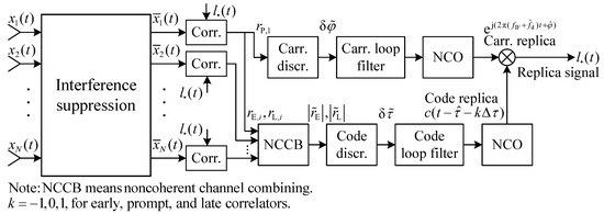
Figure 1.
Schematic diagram of the proposed method.
- (1)
- The auto-correlation matrix is estimated using the received snapshots. Then, the interference is suppressed to obtain through Equation (14).
- (2)
- Each channel of is correlated with the local replica signals, and the correlator outputs are obtained, as shown in Equation (19).
- (3)
- The noncoherent channel combining is implemented by exploiting the correlator outputs using Equation (20).
- (4)
- (5)
- The raw discriminator outputs are fed into loop filters, and the new local replica signals are generated for continuous signal tracking.
3.4. Comparison with Existing Methods
From the previous subsection, it is shown that the proposed method can be implemented in a simple logic without any other auxiliary information or sensors. This subsection further compares it with several existing methods. For a fair comparison, in addition to the PI algorithm, two blind algorithms that require signal tracking are considered in this work.
The first algorithm is called MVDR-like in this paper, which is an extension of the algorithms in [13,14]. Specifically, each component of is individually tracked to estimate the projected satellite steering vector as
where is the integrated carrier phase difference between the nth channel and the first channel. The corresponding output signal is obtained as
The second algorithm is the well-known MMSE algorithm, which is a typical algorithm that uses the reference signal waveform for beamforming. The MMSE weight vector can be formulated as [15]
where denotes the cross-correlation vector between the received signal vector and the reference signal , and denotes the conjugate operation. Using Equations (26) and (14) in Equation (3) yields
- (1)
- (2)
- For the MVDR-like algorithm, in the ideal case, there are no tracking errors in the integrated carrier phase for each channel, and . Therefore, the array gain for the satellite signal is maximized, because in this case, the two vectors and are parallel, as explained in Equation (17).
- (3)
As a matter of fact, the practical reference signal for the MMSE algorithm is recovered from the receiver tracking loop, so it is denoted as to distinguish. It should be pointed out that the tracking errors are unavoidably involved in and . Therefore, the performance of the MVDR-like and MMSE algorithms is degraded in two aspects. (1) The tracking errors in and reduce the their correlation with , thus degrading the algorithm performance, especially under weak signal conditions. (2) The carrier tracking errors will be introduced into the output signal by array weighting, which reduces the carrier tracking precision of these algorithms. Compared to these algorithms, the proposed method is more robust, which can improve code tracking without affecting carrier tracking.
Then, the computational complexity associated to different algorithms is investigated. The proposed method with other algorithms of interest is realized using the sample matrix inversion technique. The main computational costs of processing (including anti-jamming and tracking) a K-snapshot space-time data matrix, i.e., , are evaluated, where is the sampling interval. Some variables are defined as follows: M denotes the number of satellite signals to be tracked, denotes the reference signal vector, denotes the local replica signal vector corresponding to the early, prompt, or late correlator, and denotes the corresponding correlator output.
The computational complexity for key steps of different methods are summarized in Table 1. It can be seen from the table that the complexity of the methods has the following relationship: PI < MMSE < MVDR-like ≈ Proposed. In general, the number of snapshots is much larger than the number of antennas, i.e., , so the terms containing K dominate the computational complexity. Therefore, the computational complexity of the proposed method is two to N times that of the PI algorithm, depending on M, the number of satellites to be tracked in the receiver. Despite the higher computational complexity, the proposed method can achieve better signal tracking precision and measurement accuracy, as shown in the following simulations.

Table 1.
Computational complexity for key steps of different methods.
4. Simulation Results
Several simulations are carried out in this section to verify the performance of the proposed method and compare it with existing methods that have been mentioned earlier.
4.1. Simulation Settings
In the simulations, a uniform linear array (ULA) was used to receive the GNSS signal in the jamming scenario. The structure of the ULA is shown in Figure 2. The parameters used in the simulation scenarios are listed in Table 2. Also, the tracking loop configuration is summarized in Table 3. It can be seen from Figure 2 that the steering vector has the form
where d is the array spacing, is the DOA of the incident signal, and is the carrier wavelength.
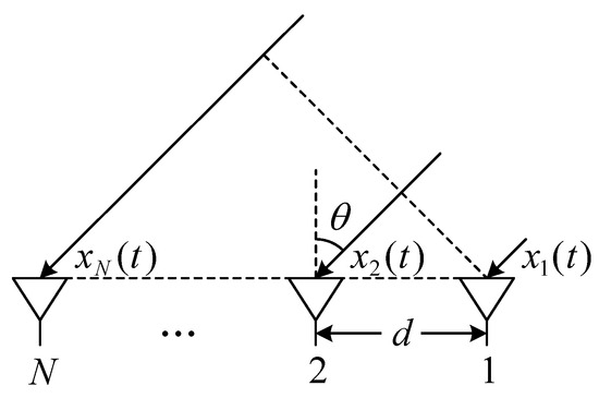
Figure 2.
Structure of the ULA.

Table 2.
Parameters used in the simulation scenarios.

Table 3.
Configuration of the tracking loop.
4.2. Tracking Error Assessment
This subsection assesses the tracking errors obtained by different methods for an intuitive view.
Figure 3 shows the code phase and carrier phase tracking errors. These results are defined as the estimated value minus the actual value recorded by the signal simulator. The constant carrier phase bias introduced by the adaptive array was subtracted in advance. From Figure 3a, it is shown that that there is substantial code phase error in the PI algorithm, because it suffers satellite signal attenuation while suppressing interference and not all signal power of different channels is used. In contrast, the other methods can significantly reduce the code phase error compared to the PI algorithm. From Figure 3b, it is shown that the carrier phase error curves of the MVDR-like and MMSE algorithms are smoother and show lagging characteristics (see the zoomed-in subfigure) compared to those of the other two methods. This is because the additional carrier tracking error is introduced by array weighting, which affects the carrier tracking results, as mentioned in Section 3.4.
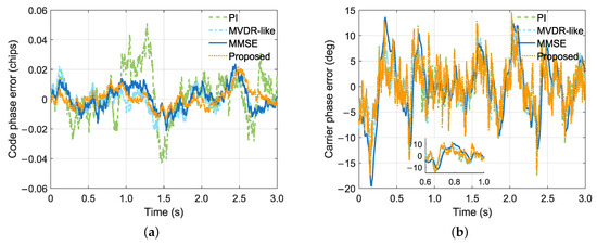
Figure 3.
Code phase and carrier phase tracking errors. (a) Code phase. (b) Carrier phase.
Figure 4 shows the cumulative distribution functions (CDFs) of the code phase and carrier phase absolute errors. The following results can be obtained from the figure. (1) The MVDR-like and MMSE algorithms can significantly reduce the code phase error but also sacrifice carrier phase precision compared to the PI algorithm. This is in agreement with the analysis in Section 3.4. (2) The MVDR-like algorithm outperforms the MMSE algorithm at the cost of increased complexity. Moreover, the proposed method performs the best with an approximate MVDR-like complexity, as analyzed in Section 3.4. (3) It should be noted that the MVDR-like and MMSE algorithms reduce the maximum carrier phase error compared to the other two methods, which is mainly due to the smoother results obtained by these algorithms. (4) The proposed method slightly reduces the carrier phase error compared to the PI algorithm because it has better code tracking, which also benefits carrier tracking since they are coupled.
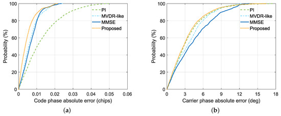
Figure 4.
CDFs of code phase and carrier phase absolute errors. (a) Code phase. (b) Carrier phase.
4.3. Discriminator Output Analysis
This subsection further analyzes the discriminator outputs obtained by different methods.
Figure 5 shows the code and carrier discriminator outputs. This figure can further explain the tracking results obtained in the previous subsection. It can be seen from Figure 5a that the code discriminator output of the proposed method is the least noisy. This proves that it can significantly reduce the code discriminator noise by properly exploiting the signal power of different channels. This explains the reason for the improvement in code phase precision of the proposed method shown in Section 4.2. The MVDR-like and MMSE algorithms cannot produce a satisfactory noise reduction performance in this weak signal condition. This is because the increased tracking errors will degrade the beamforming performance of these methods, as stated in Section 3.4. From Figure 5b, it can be seen that the proposed method can slightly reduce the carrier discriminator noise compared to the PI algorithm, as expected. In addition, the random noise in the carrier discriminator output is significantly reduced by the MVDR-like and MMSE algorithms compared to the other two methods. However, there are obvious low-frequency errors caused by the carrier tracking errors introduced by array weighting. These low-frequency errors cannot be filtered out by filter loops and actually interfere with regular carrier phase tracking, as described in Section 3.4. This explains the reason for the degradation in carrier phase precision of these algorithms shown in Section 4.2.
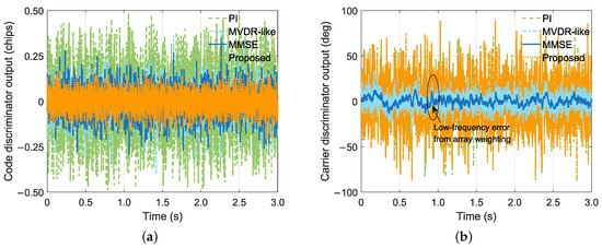
Figure 5.
Code and carrier discriminator outputs. (a) Code discriminator. (b) Carrier discriminator.
4.4. Tracking Precision Evaluation
This subsection evaluates the tracking precision obtained by different methods under different conditions.
Figure 6 shows the code phase and carrier phase tracking precision under different conditions. These results are derived from the error statistics obtained at in the range 35 to 50 dB-Hz. An analysis of the figure indicates the following. (1) The code phase and carrier phase tracking precision improves as the increases, as expected. This indicates that better signal tracking precision can be achieved by increasing the useful signal power. (2) The MVDR-like and MMSE algorithms can only improve the code phase precision compared to the PI algorithm. However, the carrier phase precision of these algorithms deteriorates accordingly whether the signal strength is low or high. (3) The code phase precision of the proposed method is the highest among all methods when the signal strength is weak, and it is comparable to the MVDR-like and MMSE algorithms when the signal is strong. (4) The proposed method can improve the code tracking precision while not affecting the carrier tracking precision, unlike the MVDR-like and MMSE algorithms. Therefore, it has a unique advantage in terms of improving the tracking precision.
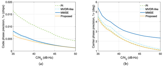
Figure 6.
Code phase and carrier phase tracking precision under different conditions. (a) Code phase. (b) Carrier phase.
5. Conclusions
In this paper, the noncoherent channel combining method was proposed for GNSS signal tracking with an adaptive antenna array. The proposed method adopts a two-stage processing architecture, which is implemented as follows. First, interference suppression is performed based on the projection technique to suppress interference. Then, noncoherent channel combining is implemented at the correlation level to exploit the useful signal power. The proposed method was compared with several representative blind beamforming methods through both theoretical analysis and simulations. The analysis and results showed that the proposed method can achieve better signal tracking precision than conventional methods. The proposed method actually represents a unified processing architecture and can be further extended. Therefore, it deserves further investigation in future work: (1) More GNSS signal components can be taken into account to achieve joint reception with an adaptive antenna array. (2) Closed-loop sequential processing can be extended to open-loop batch processing for more robust signal tracking.
Author Contributions
Conceptualization, S.L. and F.W.; methodology, S.L.; software, S.L. and C.M.; validation, H.L. and C.M.; formal analysis, S.L.; investigation, S.L.; resources, H.L. and X.T.; data curation, S.L.; writing—original draft preparation, S.L.; writing—review and editing, X.T. and F.W.; supervision, F.W. All authors have read and agreed to the published version of the manuscript.
Funding
This research was supported in part by the National Natural Science Foundation of China (Grant No. U20A0193).
Data Availability Statement
No new data were created or analyzed in this study. Data sharing is not applicable to this article.
Conflicts of Interest
The authors declare no conflict of interest.
References
- Yang, Y.; Mao, Y.; Sun, B. Basic performance and future developments of BeiDou global navigation satellite system. Satell. Navig. 2020, 1, 1. [Google Scholar] [CrossRef]
- Borio, D.; Dovis, F.; Kuusniemi, H.; Presti, L.L. Impact and detection of GNSS jammers on consumer grade satellite navigation receivers. Proc. IEEE 2016, 104, 1233–1245. [Google Scholar] [CrossRef]
- Fante, R.; Vaccaro, J. Wideband cancellation of interference in a GPS receive array. IEEE Trans. Aerosp. Electron. Syst. 2000, 36, 549–564. [Google Scholar] [CrossRef]
- Van Trees, H.L. Optimum Array Processing: Part IV of Detection, Estimation, and Modulation Theory; John Wiley & Sons: New York, NY, USA, 2002. [Google Scholar]
- Compton, R. The power-inversion adaptive array: Concept and performance. IEEE Trans. Aerosp. Electron. Syst. 1979, 15, 803–814. [Google Scholar] [CrossRef]
- Fernández-Prades, C.; Arribas, J.; Closas, P. Robust GNSS receivers by array signal processing: Theory and implementation. Proc. IEEE 2016, 104, 1207–1220. [Google Scholar] [CrossRef]
- Cuntz, M.; Konovaltsev, A.; Heckler, M.; Hornbostel, A.; Kurz, L.; Kappen, G.; Noll, T. Lessons learnt: The development of a robust multi-antenna GNSS receiver. In Proceedings of the 23rd International Technical Meeting of the Satellite Division of The Institute of Navigation (ION GNSS 2010), Portland, OR, USA, 21–24 September 2010; pp. 2852–2859. [Google Scholar]
- Yang, C.; Lin, D.M. Angles of arrival tracking of GPS signals with digital beamforming monopulse for attitude determination. In Proceedings of the 60th Annual Meeting of The Institute of Navigation, Dayton, OH, USA, 7–9 June 2004; pp. 521–532. [Google Scholar]
- Zorn, S.; Niestroj, M.; Caizzone, S.; Brachvogel, M.; Meurer, M. Self-contained antenna crosstalk and phase offset calibration by jointly solving the attitude estimation and calibration problem. In Proceedings of the 30th International Technical Meeting of the Satellite Division of The Institute of Navigation (ION GNSS+ 2017), Portland, OR, USA, 25–29 September 2017; pp. 3481–3493. [Google Scholar]
- Daneshmand, S.; Sokhandan, N.; Zaeri-Amirani, M.; Lachapelle, G. Precise calibration of a GNSS antenna array for adaptive beamforming applications. Sensors 2014, 14, 9669–9691. [Google Scholar] [CrossRef] [PubMed]
- Amin, M.; Sun, W. A novel interference suppression scheme for global navigation satellite systems using antenna array. IEEE J. Sel. Areas Commun. 2005, 23, 999–1012. [Google Scholar] [CrossRef]
- Sun, W.; Amin, M. A self-coherence anti-jamming GPS receiver. IEEE Trans. Signal Process. 2005, 53, 3910–3915. [Google Scholar] [CrossRef]
- Chen, Y.H.; Juang, J.C.; De Lorenzo, D.S.; Seo, J.; Lo, S.; Enge, P.; Akos, D.M. Real-time software receiver for GPS controlled reception pattern antenna array processing. In Proceedings of the 23rd International Technical Meeting of the Satellite Division of The Institute of Navigation (ION GNSS 2010), Portland, OR, USA, 21–24 September 2010; pp. 1932–1941. [Google Scholar]
- Chen, Y.H.; Juang, J.C.; Seo, J.; Lo, S.; Akos, D.M.; De Lorenzo, D.S.; Enge, P. Design and implementation of real-time software radio for anti-interference GPS/WAAS sensors. Sensors 2012, 12, 13417–13440. [Google Scholar] [CrossRef] [PubMed]
- Li, S.; Tang, X.; Ma, C.; Lin, H.; Wang, F. A blind anti-jamming algorithm for array-based GNSS receivers using the MMSE criterion. In Proceedings of the 2023 8th International Conference on Signal and Image Processing (ICSIP), Wuxi, China, 8–10 July 2023; pp. 985–989. [Google Scholar]
- Sgammini, M.; Antreich, F.; Kurz, L.; Meurer, M.; Noll, T.G. Blind adaptive beamformer based on orthogonal projections for GNSS. In Proceedings of the 25th International Technical Meeting of the Satellite Division of The Institute of Navigation (ION GNSS 2012), Nashville, TN, USA, 17–21 September 2012; pp. 926–935. [Google Scholar]
- Guo, Y.; Zou, D.; Wang, X.; Rao, Y.; Shang, P.; Chu, Z.; Lu, X. Method for estimating the optimal coefficient of L1C/B1C signal correlator joint receiving. Remote Sens. 2022, 14, 1401. [Google Scholar] [CrossRef]
- Falletti, E.; Pini, M.; Presti, L.L. Low complexity carrier-to-noise ratio estimators for GNSS digital receivers. IEEE Trans. Aerosp. Electron. Syst. 2011, 47, 420–437. [Google Scholar] [CrossRef]
- Li, S.; Ma, C.; Ma, P.; Lin, H.; Tang, X.; Wang, F. GNSS carrier tracking via a variational Bayesian adaptive Kalman filter for high dynamic conditions. In Proceedings of the China Satellite Navigation Conference, Jinan, China, 24–26 May 2024; Springer Nature: Singapore; pp. 379–389. [Google Scholar]
- Kaplan, E.D.; Hegarty, C. Understanding GPS/GNSS: Principles and Applications, 3rd ed.; Artech House: Boston/London, UK, 2017. [Google Scholar]
- Li, S.; Wang, F.; Tang, X.; Ni, S.; Lin, H. Anti-jamming GNSS antenna array receiver with reduced phase distortions using a robust phase compensation technique. Remote Sens. 2023, 15, 4344. [Google Scholar] [CrossRef]
Disclaimer/Publisher’s Note: The statements, opinions and data contained in all publications are solely those of the individual author(s) and contributor(s) and not of MDPI and/or the editor(s). MDPI and/or the editor(s) disclaim responsibility for any injury to people or property resulting from any ideas, methods, instructions or products referred to in the content. |
© 2024 by the authors. Licensee MDPI, Basel, Switzerland. This article is an open access article distributed under the terms and conditions of the Creative Commons Attribution (CC BY) license (https://creativecommons.org/licenses/by/4.0/).