1. Introduction
MIMO technology was firstly applied in the field of wireless communication. By using multiple transmitting and receiving antennas, it fully utilizes the time diversity, spatial diversity, and frequency diversity of signals, greatly improving the capacity and frequency utilization of communication systems [
1]. Due to the similarity between radar systems and wireless communication systems, inspired by MIMO communication, MIMO technology has been widely promoted and applied in the radar field, and MIMO radar has emerged as a result. It exhibits many advantages in waveform design flexibility, the simultaneous detection of the number of targets, overcoming target flicker, detecting high-speed targets, and improving resolution [
2].
MIMO radar emits orthogonal signals from multiple transmitting elements. At the receiving end, the echoes corresponding to different transmitting signals are separated through matched filtering and equivalent beamforming. The MIMO radar system can use the transmission degrees of freedom to form a virtual array [
3,
4]. Since each group of transmitting and receiving elements can form an observation channel, MIMO radar can obtain far more observation channels than the actual number of physical elements [
5], which greatly improves the utilization rate of elements and reduces the required number of elements.
In recent years, scholars have maintained a strong research interest in virtual aperture MIMO radar. Frank C. Robey et al. used the Kronecker product of the joint steering vector for MIMO radar to expand the array aperture of MIMO radar and pointed out that increasing the number of virtual elements can make target positioning, adaptive beamforming, and zero setting more flexible [
6]. Zheng et al. analyzed the impact of the sparsity of transmitting elements on the joint pattern of virtual aperture MIMO radar [
7]. Kantorj et al. from Lincoln Laboratory applied virtual aperture MIMO radar to airborne radar and studied the clutter suppression and target detection performance of airborne virtual aperture MIMO radar [
8]. Researchers are working in different directions to improve the flexibility, performance, and adaptability of radar systems.
With the help of virtual array element technology, the transmitting and receiving array is configured reasonably, allowing the radar to form a planar aperture in the observation channel and obtain three-dimensional echo signals when the number of physical elements is limited. In addition, MIMO radar echo signal acquisition does not need to rely on the accumulation of time to form a synthetic aperture and is able to complete the acquisition of three-dimensional signals in a short period of time, which is much shorter than the single-transmitter–single-receiver radar system [
9].
MIMO radar models can be broadly divided into two types with regard to how to generate and utilize multi-observation channel data: MIMO radar with widely separated antennas [
10,
11] and MIMO radar with colocated antennas [
12,
13,
14]. The array spacing of MIMO radar with widely separated antennas is very large, which can utilize spatial diversity gain to improve target detection performance. The transmitting and receiving antenna array of MIMO radar with colocated antennas is similar to traditional arrays, with small spacing between elements, and multiple observation channel data can be coherently processed together. Compared with real aperture array or phased array radar, dense array MIMO radar has improved radar performance in multiple aspects such as spatial resolution, anti-interference, parameter identification, and imaging [
15,
16]. There is a spatial convolution effect between the transmitting and receiving arrays of dense array MIMO radar. By designing the transmitting and receiving arrays reasonably, the equivalent array can effectively expand the aperture length or density of the original physical array, which is exactly the advantage of dense array MIMO radar [
17].
Although MIMO radar imaging has many advantages over traditional imaging methods, the large number of transmitting and receiving elements not only increases equipment costs but also increases system complexity. A sparse arrangement of the array will further reduce radar costs, reduce equipment weight, eliminate inter-element spacing constraints, and reduce inter-element coupling.
Sparse optimization array, using as few elements as possible to achieve the best imaging quality, is an important direction in radar imaging research. Periodic sparse distribution and random sparse distribution are two conventional optimization methods, both of which reduce the number of transmitting and receiving array elements while maintaining radar imaging performance (usually referring to the same array aperture) and are intuitive ways to solve the problem of full array [
18]. In response to the problem of image quality degradation caused by sparse arrays, this paper provides solutions from the perspective of signal processing.
The MIMO radar imaging processing algorithm is also one of the core issues in MIMO radar imaging research. The usual approach is to introduce the concept of virtual array elements under far-field conditions to simplify the echo signal model. The echo signals of each observation channel are approximately equivalent to the effect of a single transmitter and receiver with the same phase center, so as to use any classic imaging algorithm of a single-transmitter and single-receiver radar for image reconstruction [
19,
20]. Equivalent phase center is a simple method for converting the situation of transmitting and receiving separately into a single-phase center of transmitting and receiving simultaneously [
21]. It is widely used in processing radar echo signals, direction control, beamforming, target recognition, tracking, imaging, and other aspects.
However, when the target is in the near field, the target size is comparable to the size of the synthetic aperture as well as the distance from the aperture to the target, and the assumption of a planar wavefront is no longer valid. The wavefront needs to be described by a spherical wave with a Fresnel approximation to describe the phase difference between the array elements, which renders some of the well-established and effective far-field imaging algorithms for MIMO radar no longer applicable [
22].
When converting MIMO echo data into SISO echo signals and processing them based on the equivalent array, it is inevitable to encounter the problem of EPC error because there are certain errors between the equivalent phase center and the actual physical phase center in terms of echo delay, amplitude, phase information, etc. The subsequent processing results will be affected if the EPC error is not corrected. In addition, as the sparsity of the array increases and the spacing between the array elements becomes larger, the effect of this phase error becomes more and more obvious.
In summary, in order to save hardware costs and reduce signal processing complexity, it is necessary to sparsify the MIMO radar array. However, when using sparse-array traditional MIMO radar imaging algorithms to image near-field targets, significant errors can arise due to the application of the EPC principle, which can affect imaging quality. In order to solve the above problems, this paper analyzes the EPC error and proposes a modified phase error correction method based on the reference point compensation method, obtaining phase correction factors with different accuracies. Additionally, a sparse linear antenna array with periodic structure is designed, which meets the requirements of reducing system complexity and reducing system errors. The effectiveness of the proposed phase error correction method has been verified through simulation and experiments.
The paper is organized as follows.
Section 2 describes the signal model of MIMO radar, the principle of virtual aperture, equivalent phase center principle, and the near- and far-field conditions of MIMO arrays. In
Section 3, the phase error is analyzed and a modified phase error correction method is proposed. In
Section 4, simulations and imaging experiments are performed based on the designed antenna array, and the experimental results are presented and analyzed. Finally,
Section 5 summarizes the results and concludes the paper.
2. Signal Model and Phase Center Approximation
2.1. MIMO Radar Signal Model
In practical applications, linear arrays are the most common form of arrays, so it is assumed that the radar-transmitting and -receiving arrays are linear arrays. Consider a MIMO radar with
transmitting antennas and
receiving antennas; the units of the array are distributed on the x-axis, and the coordinates of the transmitting units and the receiving units are denoted as
and
. Assume that there are
point targets in the imaging area
, the target coordinates are denoted as
, and the scattering coefficient of the target is
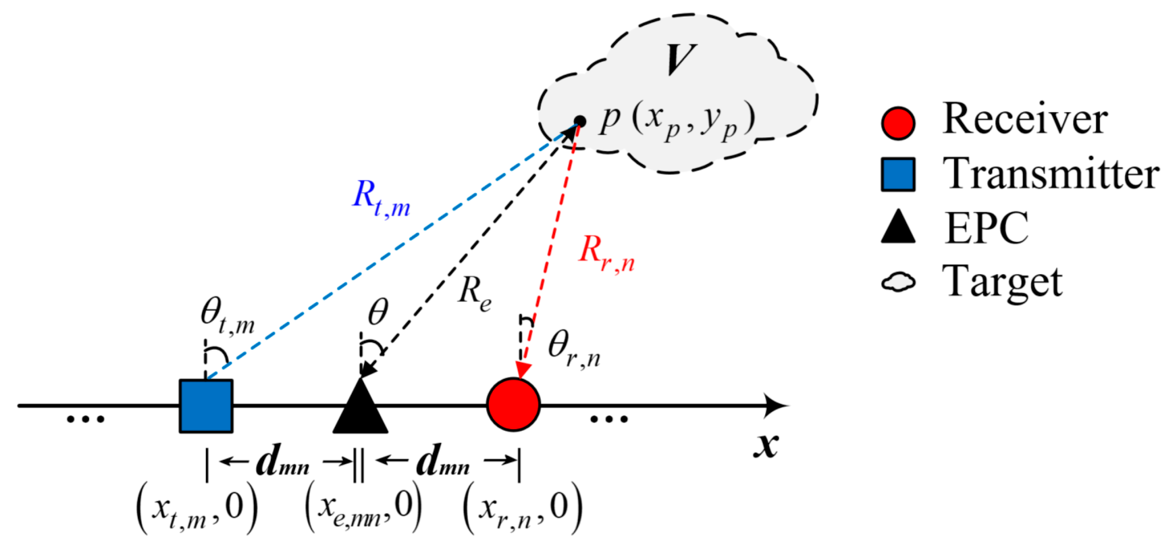
. The schematic diagram of the linear MIMO array radar echo is shown in
Figure 1.
and respectively represent the lengths of the transmitting antenna array and the receiving antenna array. represent the angles between the m-th transmitting unit and point , and represent the angles between the n-th receiving unit and point . The blue and red dashed lines represent the transmission and reception paths of the signal, respectively.
The signal emitted by the
m-th transmitting unit of MIMO radar is represented as
where
is the normalized amplitude of the transmitted signal and
is the carrier frequency.
and
, respectively, represent the distance from the transmitting phase center
m to the target and the distance from the target to the receiving phase center
n. Their coordinates are represented as
is the propagation delay from the
m-th transmitting unit to point
, and
is the propagation delay from point
to the
n-th receiving unit. Then,
where
denotes the total time delay of the signal and the electromagnetic wave propagation speed is
.
The MIMO radar irradiation signal
at a single point target
is
After being reflected by a spatial target and performing coherent detection on the echo signal
received by the
n-th receiving array element, one can obtain
The MIMO radar transmission waveform is an orthogonal waveform and is assumed to have ideal autocorrelation and cross-correlation characteristics, that is, the correlation function can be expressed as
Using the
m′-th fundamental frequency signal to perform matched filtering on the
n′-th received signal and utilizing the relevant characteristics of the transmitted signal, the output of the matched filter is
When using the m-th transmitting waveform to perform matched filtering on the n-th receiving signal, the signal of channel can be separated. At the receiving end, a set of matched filters can be used to separate the transmitting signals to obtain signals passing through different channels.
2.2. MIMO Radar Virtual Aperture
Different waveforms propagate from multiple transmission phase centers to the target simultaneously and return to multiple phase centers [
6]. Each received signal needs to process all transmitted waveforms, which have the same bandwidth and center frequency but are orthogonal in time.
According to the MIMO radar imaging model in
Section 2.1, the time delay of the signal transmitted by the
m-th transmitting element to reach the
n-th receiving element after being reflected by the target is
. The relative time delay vectors of all matched filter outputs can be represented as
,
, and
are, respectively, represented as
and
is an
dimensional vector, called the steering vector of MIMO radar.
is the delay signal vector and
is the received signal vector. The expression for MIMO radar signal transmission can be obtained:
where
represents the Hadamard product.
is an
dimensional transmitting steering vector and
is a
dimensional receiving steering vector.
where
represents the Kroncker product.
It can be seen that the MIMO radar, by transmitting orthogonal waveforms at the transmitting end and filtering them with matched filter banks at the receiving end, establishes
signal transmission channels between the transceiver and the receiver by using only
physical array elements. The system steering vectors are equivalent to the receiving steering vectors of the traditional array radar with
array elements. The positions of these
array elements are obtained by the spatial convolution of the positions of the transmitting and receiving array elements. In order to differentiate from the array formed by the actual physical array elements, these are called virtual arrays and their elements are called virtual elements. The virtual array greatly expands the array aperture, allowing MIMO radar to recognize more targets and have higher angular resolution [
18].
2.3. Principle of Equivalent Phase Center
According to the basic working principle of MIMO radar, an
-transmit
-receive MIMO radar system will generate a total of
matched filtering output results at the receiving end. The output signal before coherent processing can be simply represented as
According to Equations (2) and (3), the sum of the transmitting and receiving distances in Equation (21) is the sum of the two roots, and the phase center numbers and are independent of each other, which makes the signal model of MIMO radar very complex. Traditional coherent processing methods based on simultaneous transmission and reception, such as some synthetic aperture radar (SAR) imaging algorithms, cannot be directly applied to MIMO radar. To address the applicability issue of this model, the EPC method can be used to transform the MIMO radar echo signal model into a case of simultaneous transmission and reception.
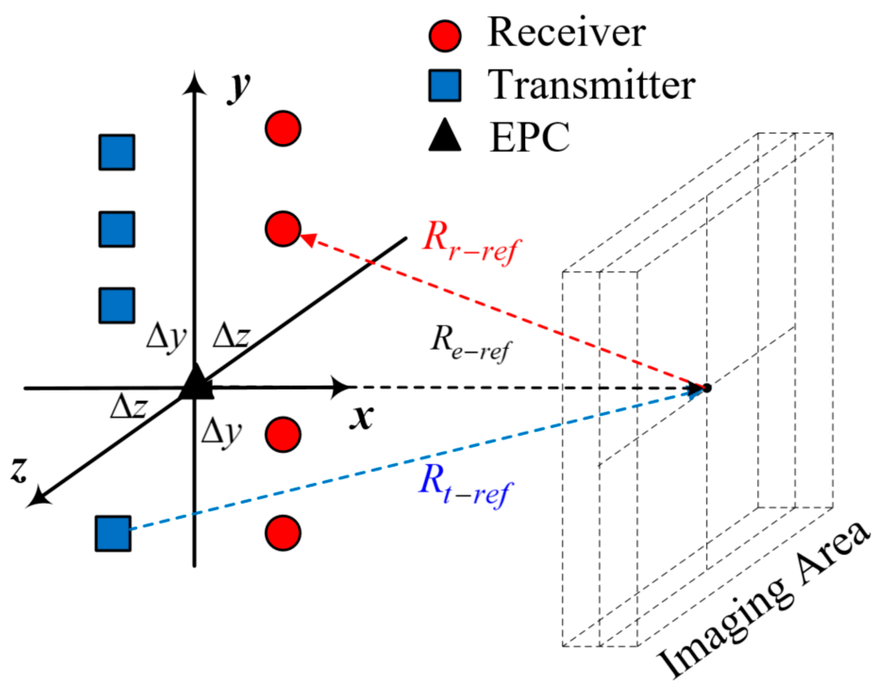
EPC is a convenient method of converting the situation of transmission and reception separation into a transceiver-synchronous single phase center. Its basic principle is that a pair of transmitting and receiving elements can be equivalent to a phase center with the same transmitting and receiving separation located at their center positions (as shown in
Figure 2). The difference in distance traveled due to this equivalence will result in a phase error that needs to be compensated.
The coordinates of the EPC are the midpoint of the coordinates of the transmitting and receiving antennas, which can be expressed as
The distance
from the EPC to the target can be expressed as
Therefore, by properly configuring the transceiver array and combining EPC operations, the multi-transceiver combination signal model of MIMO radar is simplified into a uniform linear array model, which will be very convenient for subsequent processing.
In the fields of engineering and communication, the EPC method is widely used because it provides a simple and effective way to describe and simulate antenna systems. This method can greatly simplify the complexity of system design and analysis while maintaining reasonable accuracy. The EPC method can be applied to different types of antenna structures and array configurations, and can be adjusted according to specific scenarios and requirements to meet the needs of different systems.
2.4. Near-Field and Far-Field Conditions for Linear MIMO Arrays
For traditional radar arrays, the assumption that the target is located in the far field must meet the following conditions [
23]:
where
is the target distance,
is the array aperture length, and
is the transmission signal wavelength. Unlike the far-field case, the wavefront of an electromagnetic wave under near-field conditions has significant curvature and cannot be approximated as a plane. The difference in distance between the target and each array element is not only related to its angle relative to the array, but also affected by its distance to the array. The difference in distance
between the target and the different array elements is usually not equal to the distance difference
under far-field conditions.
Similar to traditional array radar, MIMO radar also requires certain conditions to assume that the target is located in the far field. However, due to the structural characteristics of MIMO radar with multiple transmissions and multiple receivers, its far-field assumption is relatively complex compared to traditional arrays. Under the condition that the length of the transmitting and receiving array remains fixed, when the target distance increases, the wavefront curvature decreases. Then, the phase difference corresponding to the longest and shortest transmission paths between the transceiver and receiver arrays is used as the demarcation between the far field and the near field, and there are
Assuming that the lengths of the transmitting array and receiving array are
and
, respectively, the leftmost elements of the transmitting and receiving arrays, i.e., the abscissa of the first element, are
and
, with the target located at
. The expressions for
,
,
, and
in Equation (20) need to be determined based on the positional relationship between the target and the array. The specific derivation process of the expressions is provided in
Appendix A.
It can be seen that, when the far-field conditions are met, there is a constraint relationship between the relative position of the transmitting and receiving array and the target, the length of the array, and the signal wavelength.
To maximize the multi-channel advantage of MIMO radar, array design typically involves an integer multiple of the length of the transmitting and receiving array, such as
, and the array is symmetrically placed about the centerline of the imaging area. Therefore, assuming that the target is located on the
y-axis and that the distance from the line where the transmitting and receiving array is located is
, that is, the coordinate is
, the transmitting and receiving arrays are symmetrical about the origin. At this point,
,
,
. According to Equations (20), (A5), and (A6), the constraint conditions for MIMO radar to approximate the far field are as follows (Equations (A5) and (A6) are shown in the
Appendix A):
When
, this can be solved as follows:
where
When
, the length of the transmitting array and the receiving array are equal, as determined by Equation (21):
According to the existing mainstream security imaging technology, the frequency of electromagnetic waves emitted by radar is higher than 70 GHz, and the imaging distance to the human body is generally not less than 0.2 m. By substituting the above data into Equation (24), the array length is calculated to be 2.93 cm. Such a small radar aperture does not meet the resolution requirements for security checks, and it is also far from the size of existing security equipment in reality. Therefore, during human security checks, the far-field conditions of MIMO radar are completely not met, and it is necessary to improve the imaging algorithm or correct the echo data.
3. Phase Error Analysis and Correction
There is an error in the two-way distance from the equivalent phase center to the target and the sum of the distances from the transmitting and receiving elements to the target. This distance error will cause phase confusion to the echo data and affect the results of coherent processing. In the near-field scenario, the error is relatively large when directly processing according to the phase center, so it is necessary to perform phase error compensation on the equivalent data.
3.1. Reference Point Compensation Method
Since the traditional SISO 3-D synthetic aperture imaging algorithm has many research results and is relatively mature, the most intuitive idea to solve the fast imaging problem in a MIMO system is to convert the MIMO echo data into SISO echo signals and then use the existing mature algorithms to process them directly [
24,
25].
When applying the ideal reference point compensation method [
26], it is necessary to first define a reference center point in the target scene. Generally, the center point of the imaging scene is selected and represented by
, as shown in
Figure 3. The SISO data converted directly from the raw echo according to the phase center position
are denoted by
, and their corresponding transmit antenna position is denoted by
, while the receive antenna position is denoted by
.
The distances from the transmitting antenna, receiving antenna, and equivalent phase center to the reference point are
The phase error compensation is as follows:
where
denotes the phase history of the actual transceiver unit to the reference center and
denotes the phase history from the EPC to the reference center, i.e.,
Since the above phase error compensation is based on a reference point at the center of the target scene, if there is only one target point in the imaging scene located at the reference point, this compensation can be considered to be completely accurate. However, this is not consistent with the actual situation because the actual imaging target is continuous and unknown distribution. Therefore, it is necessary to conduct a general analysis of the phase error caused by the equivalent phase center of the target at any position, in order to make the correction method universal.
3.2. EPC Phase Error Analysis and Correction
3.2.1. Definition and Representation of Equivalent Phase Center Error
By using Equation (28) to perform phase compensation on Equation (16), it can be obtained that
Equation (29) is the representation of the echo signal of the equivalent array, which is reflected in the signal form of a single variable (EPC position variable ), greatly simplifying the signal model of MIMO radar. However, the EPC error represented by Equation (28) is coupled with the target position, and, usually, the target position is unknown, so it is not possible to accurately obtain this error expression, and necessary basic theoretical analysis is needed.
Use
to represent the interval between the transmitting phase center and the EPC (equal to the interval between the receiving phase center and the EPC), that is, the interval between the transmitting and receiving phase centers is
. Assuming that
,
and
can be represented as
Substituting Equations (2) and (30) into Equation (28) and combining them with Equation (18) yields
It can be seen that the EPC error
is an expression for discrete variables
,
, and
. For the convenience of analysis, Equation (31) is redefined as a continuous variable function
:
In Equation (41), , , and are the continuous forms of discrete variables , , and , respectively.
Assume that the target in
Figure 2 is located in the far field of the transmitting and receiving elements, i.e., the radiation field propagates in the form of plane waves. At this time, to satisfy
, it can be considered that the EPC error can be ignored, i.e.,
. But the so-called far field is an approximation of the phase difference between the transmitting and receiving array elements and the equivalent phase center under certain conditions. When the far-field conditions are not met, the EPC error cannot be ignored. The above approximate conditions can be described as follows: the two-way wave range difference is not greater than
, and the corresponding phase difference is less than
, which leads to
Substitute Equation (33) into Equation (32):
Since the value of
is small, ignoring its effect, Equation (43) can be simplified as
When the interval between the equivalent phase center and the transmitting and receiving elements satisfies Equation (44), the EPC error can be ignored, and there is no need to compensate for the phase error caused by it.
3.2.2. Quadratic Term Correction for Equivalent Phase Center Error
When does not satisfy Equation (44), the EPC error needs to be corrected.
Represent
using the first-order and second-order Taylor series forms about
, i.e., respectively,
Because , the second-order Taylor series in Equation (36) ignores the higher-order terms of .
Although both
and
in Equation (36) are related to the target position,
changes slowly about them and can be replaced by
and
at the target reference center point. The specific value of
is known, so the quadratic term in Equation (36) is relatively easy to obtain. Considering that Equation (36) is an approximate representation of the EPC error, it has a certain deviation from reality.
is an accelerated incremental change about
. When
increases to a certain extent, the deviation of Equation (36) will increase, which will affect the phase compensation operation. Therefore, Equation (36) can only accurately compensate the phase error within a certain range. The EPC error correction accuracy can also be selected as
in Equation (33), so that, when the quadratic term is used to correct the EPC error, the approximation error satisfies the following conditions:
The range of values of
can be determined by Equation (37). Specifically, when the target is located at the center of the transceiver unit, i.e.,
, the range of values of
can be obtained as
In the above analysis process, the upper limit of error correction accuracy is
, while the lower limit can be set to 0, which means that the EPC error is completely corrected. When the EPC error is fully corrected, Equation (37) can reach the lower limit of error correction, and Equation (37) can be rewritten as
Let
; Equation (39) can be abbreviated as
Since
, its higher terms
and
satisfy
,
. Equation (40) can be solved for
corresponds to the case where the target is located on the x-axis, i.e., the target and the antenna array are in the same straight line, which is generally not possible. The quadratic term (Equation (36)) is able to fully correct the EPC error when , i.e., when a specific line-of-sight angle is satisfied between the equivalent phase center and the target.
3.2.3. High-Order Term Correction of Equivalent Phase Center Error
The matched filter output at the receiver of the MIMO radar corresponds to all the pairwise combinations of transceiver phase centers, and, generally, the spacing between different transmission and reception pairing combinations is not the same, so that many different values of are obtained. In the case of multiple receiving and transmitting phase centers, some larger values of are possible, which cannot meet Equation (37). When using Equation (36) for EPC phase compensation, there is a large approximation error, which needs to consider the influence of high-order terms in the Taylor series expansion.
The
k-th-order Taylor series of
is
The
k-th partial derivative in Equation (42) can be obtained as
where
is the coefficient. The approximate error generated when using
k-th-order Taylor series to correct the EPC error can be expressed as
If the value of
is within the convergence domain of the Taylor series, Equation (44) can be written as
Combining with Equation (43), the ratio of the preceding and following terms above the second order in the
expansion can be expressed as
where
is required to be an even number. Generally,
is much greater than
, and, as
increases, the ratio of Equation (46) should be on a very small order of magnitude. This indicates that the absolute value of the latter term in Equation (45) is much smaller than the previous term, so Equation (45) only needs to be replaced by the first term (
). At the same time, the approximation error is still measured according to the error correction accuracy of
, and, of course, higher-error correction accuracy can also be selected. As a result, the following relationship can be obtained:
where
is an odd number. When
is an even number, one term should be extended backwards. By using Equation (47), it is convenient to determine the range of values for the accuracy of
error correction corresponding to
when using higher-order terms to correct EPC errors.
Through the analysis of the Taylor series expansion mentioned above, one property of the EPC error can be summarized: when the value of does not satisfy Equation (37), it is necessary to consider the influence of higher-order terms in the Taylor series expansion. When using k-th-order Taylor series to correct the EPC error, only the derivative term in the Taylor series expansion equation needs to satisfy Equation (47).
3.3. Modified Phase Error Correction Method
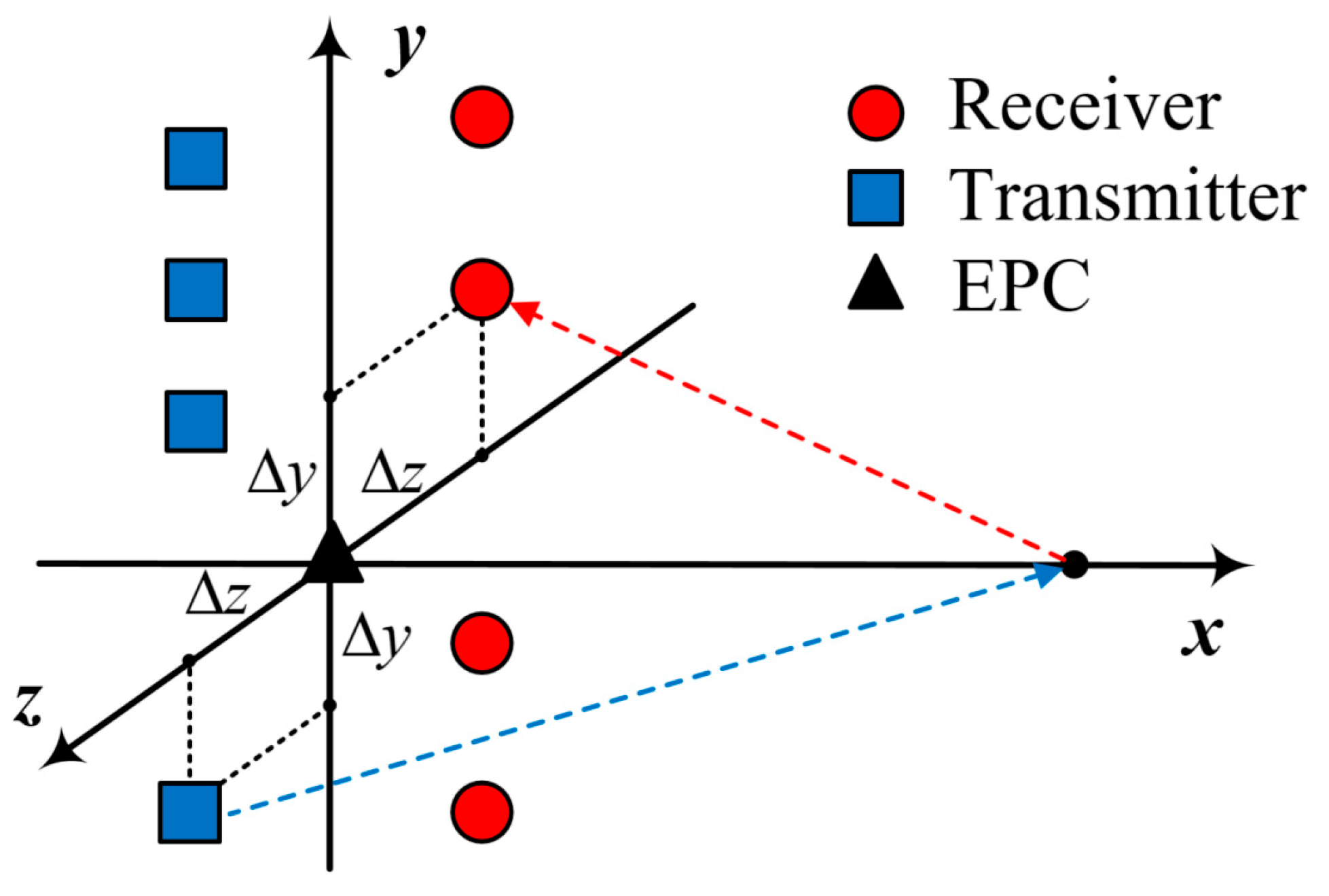
Considering that the transmitting and receiving antenna arrays may not be on the same straight line in practical application scenarios, there may be significant errors in directly equating two antenna units to their center positions. In addition, even if the transmitting and receiving arrays are not in the same straight line, the distance between the two straight lines that they are in is usually fixed. Based on the above two points, a modified method is proposed to project the position of the transmitting and receiving units onto the coordinate axis and use the projection points for phase correction.
Establish a Cartesian coordinate system according to the positional relationship shown in
Figure 4, with the two-dimensional aperture formed by the array and its motion as the plane. Assuming that the target is located on the positive half of the
x-axis, the coordinates are
. The equivalent phase center generated by a group of transmitting and receiving antennas can be set as the origin, but, to ensure the generality of the derivation, it can be assumed that the coordinate of its equivalent phase center is
, and the coordinates of the transmitting and receiving antennas are
and
, respectively. According to the layout structure of the RF chip,
is a known quantity.
According to the distance relationship shown in
Figure 4, obtain the distance between the transmitting unit and the target
, as well as the distance between the receiving unit and the target
:
In practical applications, the transmitting and receiving units’ positions are projected onto the z-axis separately instead of being directly equivalent to a central point, which further reduces the error caused by the EPC method. Obtain the distance relationships
and
of the projected positions:
Rewrite
into exponential form and expand it using Taylor’s formula, retaining its quadratic term:
Similarly, it can be inferred that
EPC error
can be obtained as follows:
Among these, the quadratic term of is the main cause of errors, and is also the quadratic term of , but it is inversely proportional to the cubic power of the distance from the transmitting and receiving unit to the target. is the fourth-order term of .
Therefore, three different levels of precision phase correction coefficients are obtained:
;
;
.
4. Simulations and Experiments
4.1. Antenna Array Design
The principle of virtual arrays is used in array design. In order to obtain as many virtual array elements as possible with fewer transmitting and receiving units (and considering system consistency), the system cascades multiple identical RF front ends to form an antenna array with a periodic structure, making the array antenna have effective sparsity efficiency and reducing the complexity and cost of the system.
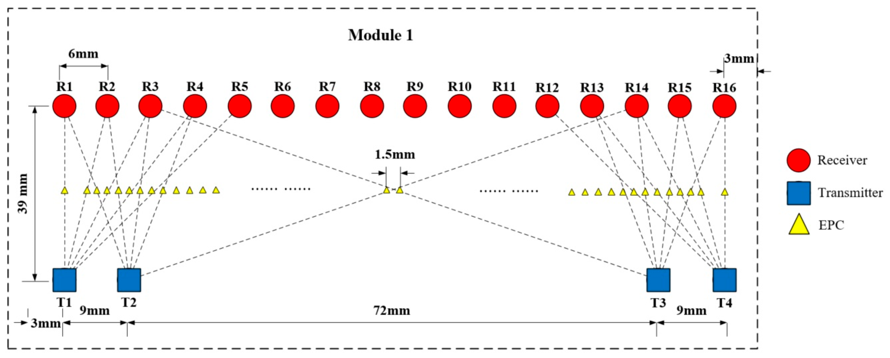
The imaging system consists of 10 imaging transceiver front-end array modules, which operate at 70~80 GHz. The length of each module is 96 mm, with an array length of 90 mm and 3 mm distance from the left and right edges of the module. The antenna array of each module consists of four transmitting units and sixteen receiving units, with the transmitting units spaced at a distance of 9 mm. Transmitting units are divided into two subarrays, and symmetrically disposed at the ends of the array. The spacing of the receiver units is 6 mm, which is uniformly distributed throughout array. Each transmitting and receiving unit can be controlled by electrical signals generated by hardware modules such as FPGAs to arrange the antenna units involved in each signal transmission and reception. The layout of the antenna units and corresponding equivalent phase centers (EPCs) in one module is shown in
Figure 5, and the obtained virtual array has an element spacing of 1.5 mm. The total length of the array composed of 10 modules is 954 mm; it contains 22 transmitting units and 160 receiving units. By selecting the units involved in transmission and reception through electrical signals, a total of 640 EPCs are generated. Among them, 633 consecutive and uniformly distributed EPCs are selected out for signal processing and image reconstruction [
27].
The system forms a two-dimensional aperture through the combination of program control and mechanical scanning. The two-dimensional aperture plane consists of the antenna array direction and the direction of mechanical motion perpendicular to the antenna array, both of which are perpendicular to the direction of distance change. In addition, the system transmits electromagnetic waves with changing frequency, so as to collect the distribution information of the measured target in the distance direction and finally realize the three-dimensional imaging of the target. The step size and the number of moving points of mechanical scanning can be set according to the size of the imaging area to ensure the complete imaging of the target.
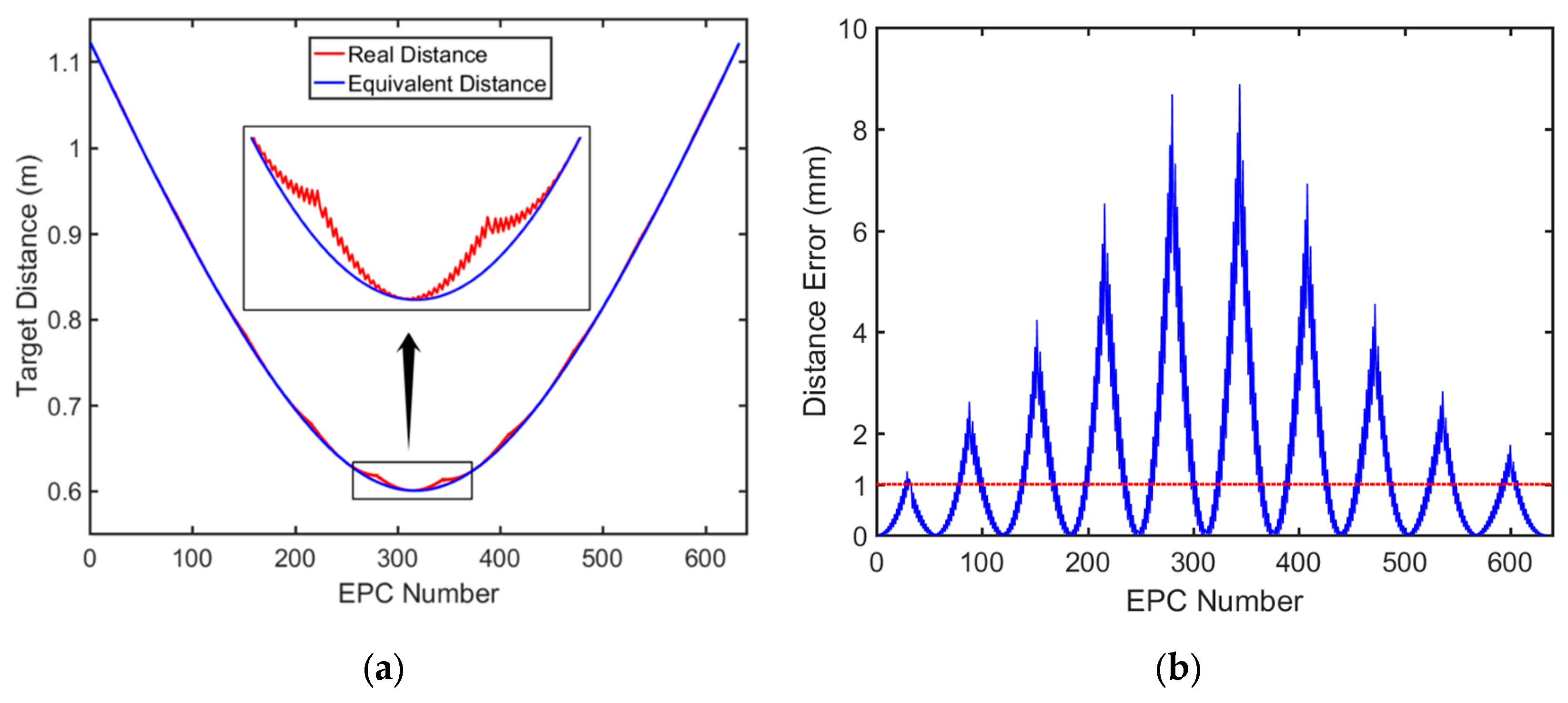
When a point target is located at the center of the array, 0.3 m away from the array, the actual distance from the target to each set of transmitting and receiving units and the equivalent distance to the EPC generated by them can be calculated based on the position of the array transmitting and receiving units. The relationship between the two-way distance and EPC can be plotted as a curve, as shown in
Figure 6a. At the same time, the difference between the equivalent distance and the actual distance at each EPC position can be calculated, and the relationship between the two-way distance error and EPC can be plotted as a curve, as shown in
Figure 6b. The value of the distance error increases as the target approaches the center position of the array.
Because the system operates at 70–80 GHz with a center frequency of 75 GHz, the corresponding
is 1 mm, marked with a red dashed line in
Figure 6b. It can be seen that the distance error generated by the EPC in most positions is greater than
, which does not meet the far-field conditions proposed earlier and also proves the necessity of phase error correction.
4.2. Simulations and Analysis
To verify the proposed phase correction method, simulations were carried out using MATLAB R2023a (MathWorks, Natick, MA, USA) on a PC equipped with Microsoft Windows 10, Intel® Core™ i7-9700 CPU @3.00 GHz (Intel Corporation, Santa Clara, CA, USA) and 16 GB RAM (made in USA), and the system has a 64-bit operating system.
Using the array described in
Section 4.1 for simulation, the array consists of 22 transmitting units and 160 receiving units, which are combined in advance to form 633 consecutive and non-repeating equivalent phase centers for imaging.
The transmitted signal had a frequency range of 70~80 GHz, and 81 points were sampled in steps of 125 MHz.
Wavenumber domain algorithm RMA was used in the simulations.
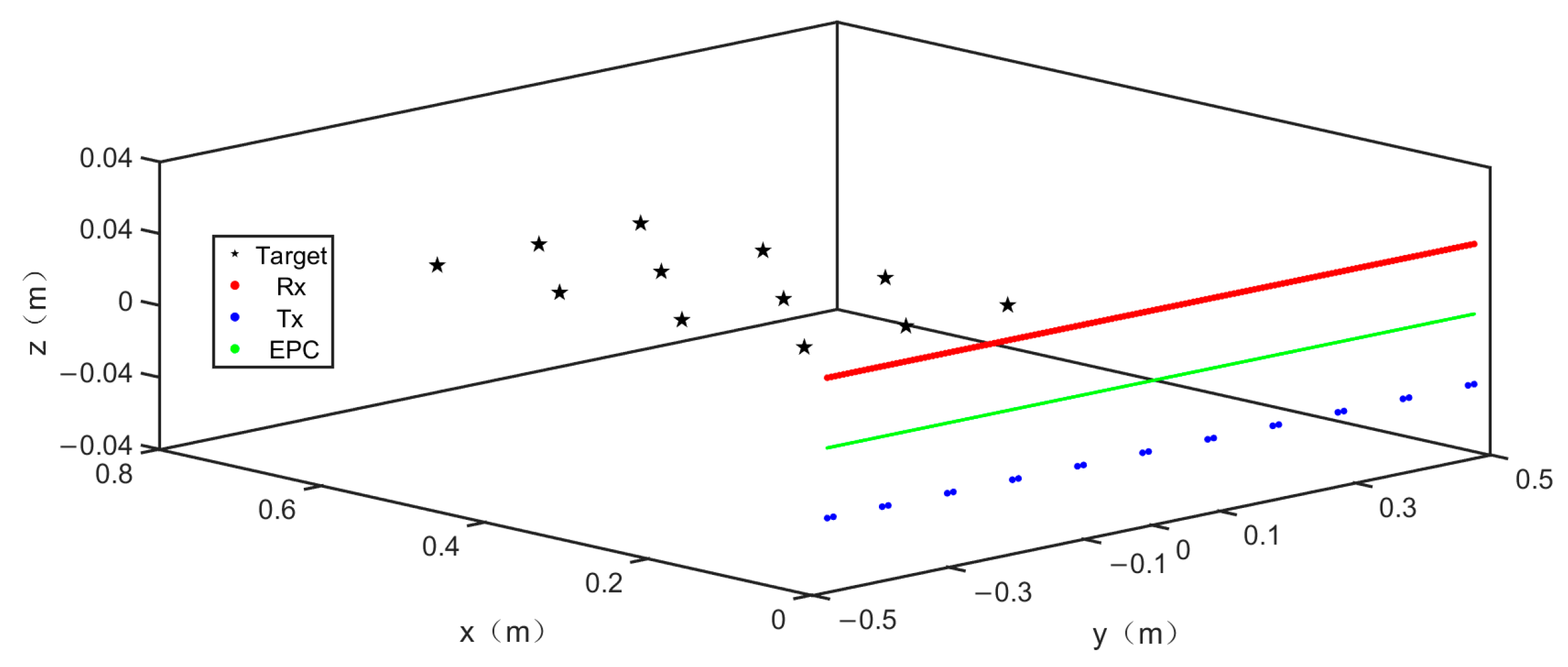
The simulation targets were set as four groups of point targets, located 0.3 m, 0.45 m, 0.6 m, and 0.75 m away from the antenna array, to investigate the focusing ability of the array and imaging algorithm on targets at different distances. The number of target points in each group is 3, with a 15 cm interval between them. The second of the three-point targets in each group was placed at the center of the array, directly in front of the array. The simulation scene diagram is shown in
Figure 7.
According to the phase correction coefficients obtained in
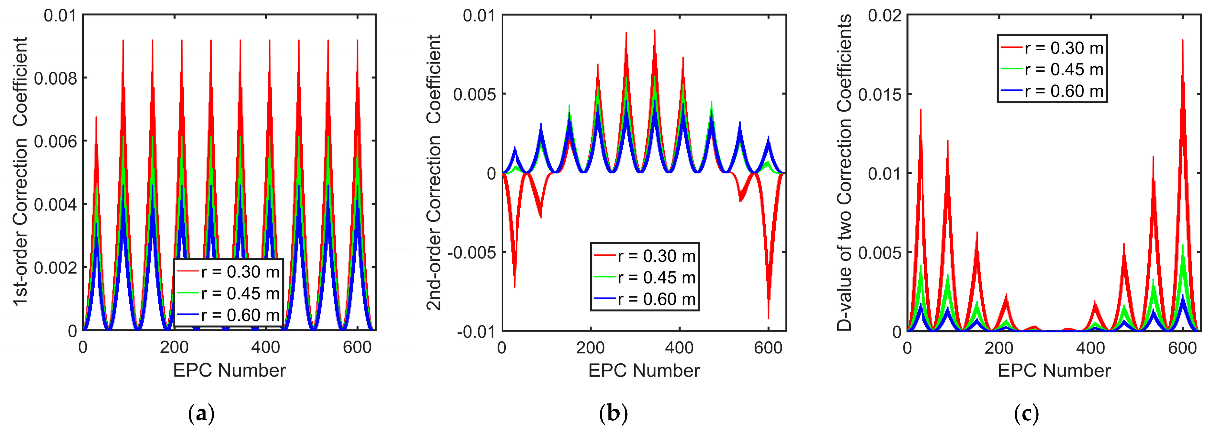
Section 3.3, the first-order correction coefficient, second-order correction coefficient, and their difference values are plotted at 0.3 m, 0.45 m, and 0.6 m from the array, and the curves are shown in
Figure 8.
Since the array structure is periodic, the first-order correction coefficient shows roughly periodic variations with a period of 64 EPCs. The periodic regularity of the second-order correction coefficient and the difference between the two correction coefficients is weakened because their expressions contain terms inversely proportional to the third power of distance that are related to the coordinate values of EPC. But their curves still roughly maintain symmetry. The absolute value of the correction coefficient becomes smaller as the distance increases, which is in accordance with the objective law. When the target is far enough away from the array to meet the far-field conditions of a MIMO array, phase correction can be not required.
In the simulation,
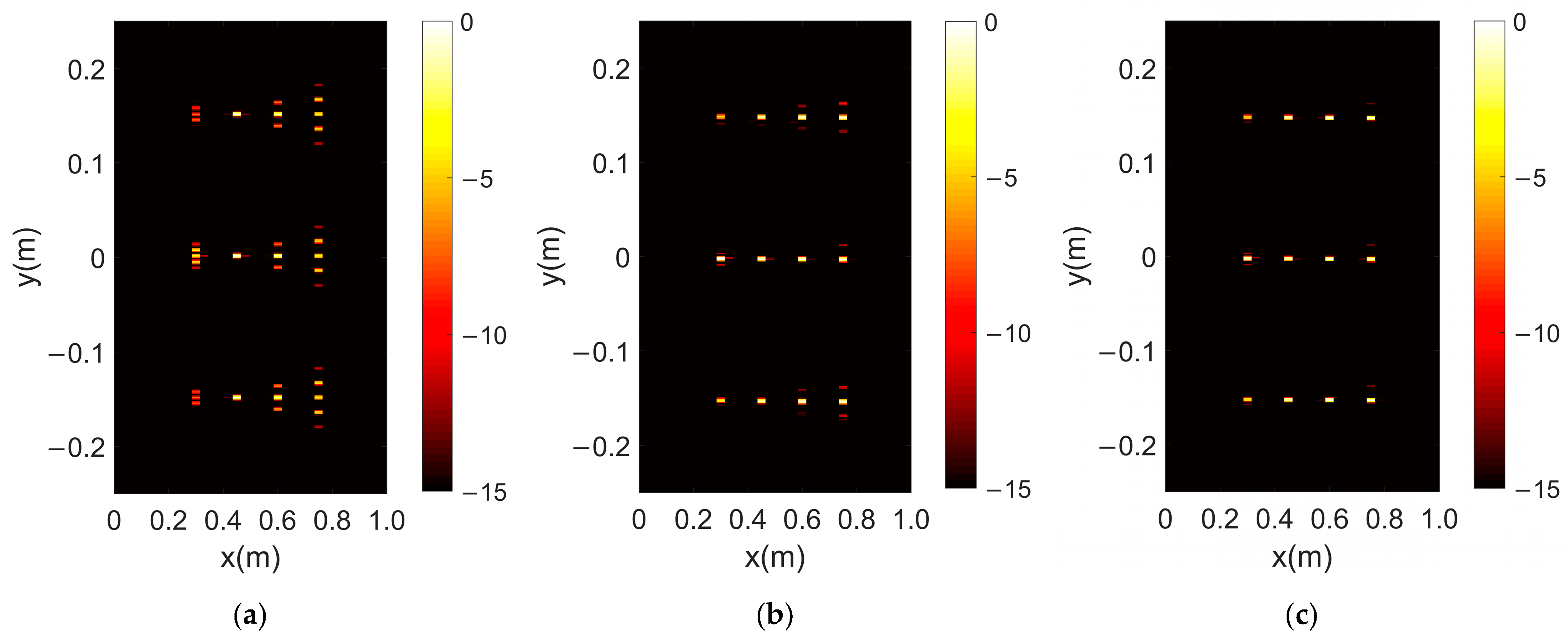
, i.e., the distance where the three point targets in the second group are located, is taken as the reference distance, and the 2-D imaging results obtained are shown in
Figure 9. From
Figure 9a, it can be seen that only the point targets at the reference distance have good focusing effect, while the targets at the other three distances show the phenomenon of defocusing. Among them, the three point targets at
, which is farthest away from the reference value, have the most serious defocusing degree.
The first-order and second-order corrections are applied to the echo signal using the phase correction coefficients obtained in
Section 3.3, and the obtained imaging results are presented in
Figure 9b,c, respectively. Compared with the uncorrected imaging results, the corrected images have better imaging quality at various target positions, and the defocusing situation is also solved to a certain extent. The most significant improvement effect is on the three-point targets located in
.
Further quantitative analysis was conducted on the results of the two corrections, and the echo intensity curve of the target along the array direction at the same distance from the antenna was plotted, as shown in
Figure 10.
Figure 10 shows the uncorrected, first-order-corrected, and second-order-corrected echo intensity curves with different colors for targets located at 0.3 m, 0.45 m, 0.6 m, and 0.75 m. Except for the echo curve at the reference distance
in
Figure 10b, at the peaks of the other three sets of curves, each peak of the corrected curve becomes prominent and unique, achieving the focusing effect on the target. Among them, in
Figure 10a, several sidelobes around the peak value of the point target are marked with circles, and the second-order-corrected sidelobe value is lower than the first-order-corrected sidelobe value. Based on the imaging results in
Figure 9, the three points located at
have the most severe defocusing of the target. Observing their echo curves, the values of the sidelobes around the peak are almost equivalent to that of the peak, severely degrading the imaging quality. In
Figure 10c,d, the maximum sidelobe values around each peak of each group of curves are marked with data labels and listed in
Table 1.
Analyzing the data in the table, the following conclusions can be drawn:
The proposed correction method can reduce the magnitude of the sidelobe of the echo curve and realize the focusing of the target, thus improving the imaging quality;
When the targets are located at the same position, the effect of second-order correction is better than that of first-order correction;
When the target is at the same position in the array direction (same y-coordinate value), the correction effect is more significant when the target is closer to the reference distance;
When the target is at the same distance from the reference plane, the correction effect is more significant for targets closer to the center position of the array.
In the subsequent simulations, the number and arrangement of point targets were changed, and the conclusions reached remained consistent with the above four conclusions.
4.3. Measurements Results
To verify the effectiveness of the proposed correction method, we conducted actual target imaging experiments in the laboratory using our own imaging system and analyzed the experimental results.
The system adopted frequency modulated continuous wave, the carrier frequency was 75 GHz, band was 10 GHz, sampling frequency was 10 MHz, and pulse duration was 12.8 μs.
Simulation experiments were conducted on a variety of metal devices and human models carrying “dangerous objects”.
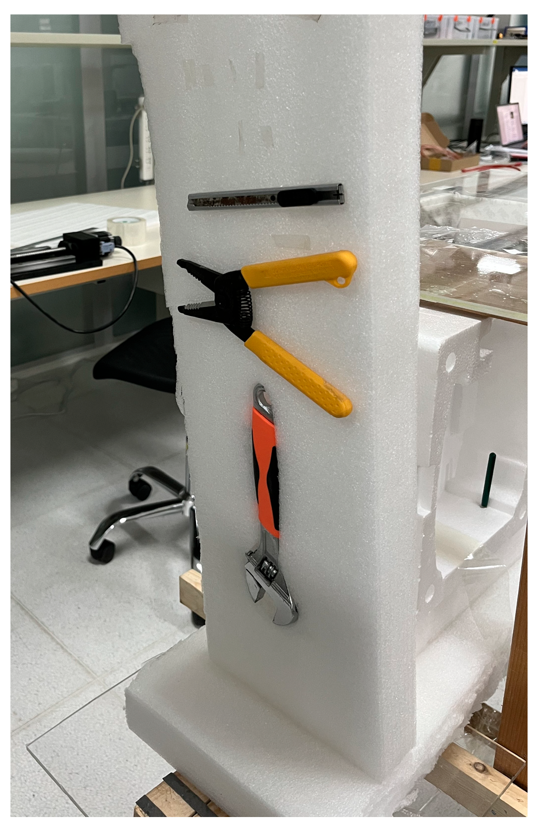
The metal targets used in the experiments included wire strippers, wrenches, paper cutters, scissors, a pistol model, etc. Optical photographs of some of the targets are shown in
Figure 11.
In the first experiment, a paper cutter, a wire stripper, and a wrench were, respectively, placed at distances of 0.25 m, 0.3 m, and 0.35 m from the antenna array. The lengths of the paper cutter, wire stripper, and wrench are approximately 12 cm, 16 cm, and 27 cm. The widths of them are approximately 1 cm, 11 cm, and 7 cm, respectively. The reference distance is 0.3 m. The experimental scenario is shown in the
Figure 12 and the imaging results are shown in
Figure 13.
Figure 13a shows the imaging results before phase error correction. Three targets at different distances can each obtain relatively complete imaging results, but a part of the contour at the left front end of the wire stripper is unclear. The imaging results of the wrench are relatively “dim” compared to the other two targets, and there is noise in the background.
Figure 13b shows the results of first-order phase correction. The contours of all three targets are complete and clear, and the brightness of the targets is improved compared to
Figure 13a, while eliminating noise in the background.
Figure 13c shows the result after second-order phase correction, which is not significantly different from the imaging result in
Figure 13b. However, the stripes on the wrench and wire stripper are more prominent, showing more details of the object.
Additional experiments were conducted to simulate real security check scenarios. The imaging target was a human model with metal materials. The model had a metal pistol model hanging on their chest, 0.25 m away from the antenna array.
Figure 11b shows the optical photograph of the pistol model, and the imaging results of the experiment are shown in
Figure 14.
Figure 14a shows the imaging results before phase error correction, which can detect the presence of the pistol model under clothing occlusion and present a rough outline, but the target is not clear enough.
Figure 14b,c shows the results after first-order and second-order phase correction, respectively. There is not much visual difference between the two results, and both can clearly image the pistol model without any poor focusing effect. They also demonstrate more details than those in
Figure 14a.
The above experimental results indicate that the proposed phase correction method can effectively correct phase errors generated by the equivalent phase center principle, solve the problem of a poor focusing effect when MIMO radar uses the wavenumber domain algorithm to image targets at non-reference distances, and significantly improve imaging quality.

