Article

A Persistent Scatterer Point Selection Method for Deformation Monitoring of Under-Construction Cross-Sea Bridges Using Statistical Theory and GMM-EM Algorithm

1
China Earthquake Networks Center, Beijing 100045, China
2
Hydrogeology and Engineering Geology Team of Beijing, Beijing 100195, China
3
School of Geomatics and Urban Spatial Informatics, Beijing University of Civil Engineering and Architecture, Beijing 102616, China
4
China Association of Construction Education, Beijing 100831, China
*
Author to whom correspondence should be addressed.
Remote Sens. 2024, 16(12), 2197; https://doi.org/10.3390/rs16122197
Submission received: 5 May 2024 / Revised: 11 June 2024 / Accepted: 14 June 2024 / Published: 17 June 2024
(This article belongs to the Special Issue Analysis of SAR/InSAR Data in Geoscience)

Abstract

:
Using traditional algorithms to identify persistent scatterer (PS) points is challenging during bridge construction because of short-term changes at construction sites, such as earthworks, as well as the erection and dismantling of temporary structures. To address this issue, this study proposes a PS point selection method based on statistical theory and Gaussian Mixture Model-Expectation Maximization (GMM-EM) algorithm. This method adopts amplitude information as an incoherence evaluation indicator. Furthermore, the statistical median of the amplitude dispersion index and amplitude mean is screened twice to extract a set of candidate points, including PS points that exhibit stable backscattering over long durations. Temporal coherence is simultaneously used as the coherence evaluation indicator. Another candidate point set is obtained by extracting high-coherence PS points using the GMM-EM algorithm. These sets of candidate points are then combined to obtain a final PS points set. In the experiment, the deformation monitoring of the under-construction Shenzhen-Zhongshan Cross-Sea Bridge in China was selected as a case study, with 28 Sentinel-1A images used as the data source for PS selection and deformation information extraction. The results show that the proposed method enhanced the density and quality of PS points on the under-construction cross-sea bridge compared to existing PS selection methods, thus offering higher reliability. Deformation analysis further revealed fluctuating deformation trends at characteristic points of the Shenzhen-Zhongshan Cross-Sea Bridge, indicating the occurrence of elastic deformation during its construction.

1. Introduction

During the construction of a sea-crossing bridge, structural changes such as the stacking of construction materials and movement of temporary support structures can displace target scatterers in Synthetic Aperture Radar (SAR) images, thereby diminishing image coherence. Obstructions at construction sites, such as buildings and mechanical equipment, also induce multiple scattering of signals that result in decreased image resolution and altered backscattering coefficients, further complicating the identification of persistent scatterer (PS) points. Furthermore, the different types of surface coverage at construction sites, including soil, water areas, and vegetation in surrounding urban areas, influence the reflection and propagation of microwave signals [1,2]. These factors collectively affect SAR image quality and the selection of PS points. The quantity and quality of PS point selection are pivotal for time series InSAR applications in monitoring infrastructure such as bridges, potentially determining the success or failure of subsequent deformation inversion [3,4]. In such dynamic settings, PS point selection methods can ascertain the relationship between PS point density, distribution, and monitoring targets. This has significant research implications and advances the theoretical framework of the time series InSAR technique for monitoring complex engineering structures such as sea-crossing bridges.
There are currently three main PS point selection methods [5,6,7,8]. The first method is the coherence coefficient, which computes N coherence coefficients of N interferograms per pixel using a defined window and establishes a threshold rule for point selection. While conceptually straightforward and computationally convenient, the efficacy of this method depends on factors such as window size, pixel inclusion criteria in the window, and the choice of reference image. All of these factors influence coherence coefficient estimation and PS points reliability [9,10,11,12]. The second method is the amplitude deviation index, which gauges phase noise levels by measuring pixel amplitude dispersion of high signal-to-noise ratio point targets, thus enabling PS point selection based on amplitude dispersion index thresholds [5,6,7]. While applicable to radiometrically corrected images, this method overlooks PS points scattering characteristics in favor of stability. The third method is the phase dispersion index, which identifies PS points as pixels with phase dispersion below a specified threshold, offering computational simplicity and independence from adjacent points. However, this method has poor reliability due to noise and difficulty ensuring PS points stability, given its sole reliance on phase data. To enhance PS point selection algorithms, researchers proposed a hybrid approach, combining the coherence coefficient and amplitude dispersion index into a dual threshold method [13,14]. Leveraging both coherence and amplitude information, this hybrid method utilizes the robust scattering and stability traits of PS points to provide more effective and reliable PS point selection. However, temporary site changes cause scattering intensity fluctuations during sea-crossing bridge construction, reducing PS points density and reliability, and subsequently impeding accurate deformation monitoring of bridges under construction.
In summary, this study used a PS point selection method incorporating statistical theory and the Gaussian Mixture Model-Expectation Maximization (GMM-EM) algorithm to enhance the density and quality of PS point identification for sea-crossing bridges under construction. This method utilizes amplitude information as an incoherence evaluation indicator, employing a statistical median of amplitude dispersion index and amplitude mean for dual screening to extract PS points exhibiting sustained backscattering as a set of candidate points. Additionally, temporal coherence served as the coherence assessment index, with the GMM-EM algorithm used to identify high-coherence PS points as another set of candidate points [15,16]. Building on this foundation, a set-based approach is adopted to merge the two candidate point groups and derive the final PS points set, thereby enhancing the quantity and quality of identifiable PS points on sea-crossing bridges under construction. The Shenzhen-Zhongshan Cross-Sea Bridge is used as a case study, with 28 Sentinel-1A images as the data source for PS point identification and deformation information extraction and analysis. The research findings are significant for the deformation monitoring of infrastructure in unstable environments.

2. Materials and Methods

2.1. Study Area

Currently under construction, the Shenzhen-Zhongshan Cross-Sea Bridge is situated in China’s Guangdong province. Spanning from 113.35°E to 113.50°E and from 22.30°N to 22.35°N, the study area connects Shenzhen, Zhongshan, and Nansha district in Guangzhou (Figure 1). It starts from the Hezhou Interchange in Shenzhen’s Bao’an district and terminates at the Hengmen Interchange in Zhongshan city. Comprising the Zhongshan Bridge, West Navigation Hole Bridge, Lingdingyang Bridge, and East Non-Navigation Hole Bridge from west to east, this bridge–tunnel combination spans a total length of 16.9 km. Notable features include the 580 m Zhongshan Bridge and 1638 m Lingdingyang Bridge. Each end of the tunnel features an artificial island, with the east island measuring 625 m long and 100 m wide, and the west island measuring 625 m long and 175 m wide. The study area experiences a subtropical monsoon climate characterized by long summers, short winters, mild temperatures, plenty of sunshine, and adequate rainfall.

2.2. Data Source and Preprocessing

The construction of the Shenzhen-Zhongshan Cross-Sea Bridge reached significant milestones when the main tower of the Zhongshan Bridge was completed in September 2021, and the main line was fully connected on 28 November 2023. This study used 28 Sentinel-1A ascending orbit images of the study area from 4 December 2021 to 4 May 2023. The spatial coverage of the images and the study area’s location are shown in Figure 1, while Table 1 outlines the parameters of the Sentinel-1A satellite dataset.
Original SAR data were preprocessed using GAMMA software to obtain single-look complex (SLC) data. Radiometric calibration was then performed on all images to ensure comparability and statistical relationships of the amplitude information. SAR images captured on 20 July 2022 were designated as the master images, and the remaining 27 slave images were registered to align with the master image’s pixel space. Interferometric processing of SAR images was conducted to derive amplitude and coherence information. PS points were identified based on this information using the PS point selection method proposed in this study.

2.3. A Persistent Scatterer Points Selection Method for Deformation Monitoring of Under-Construction Cross-Sea Bridges Using Statistical Theory and GMM-EM Algorithm

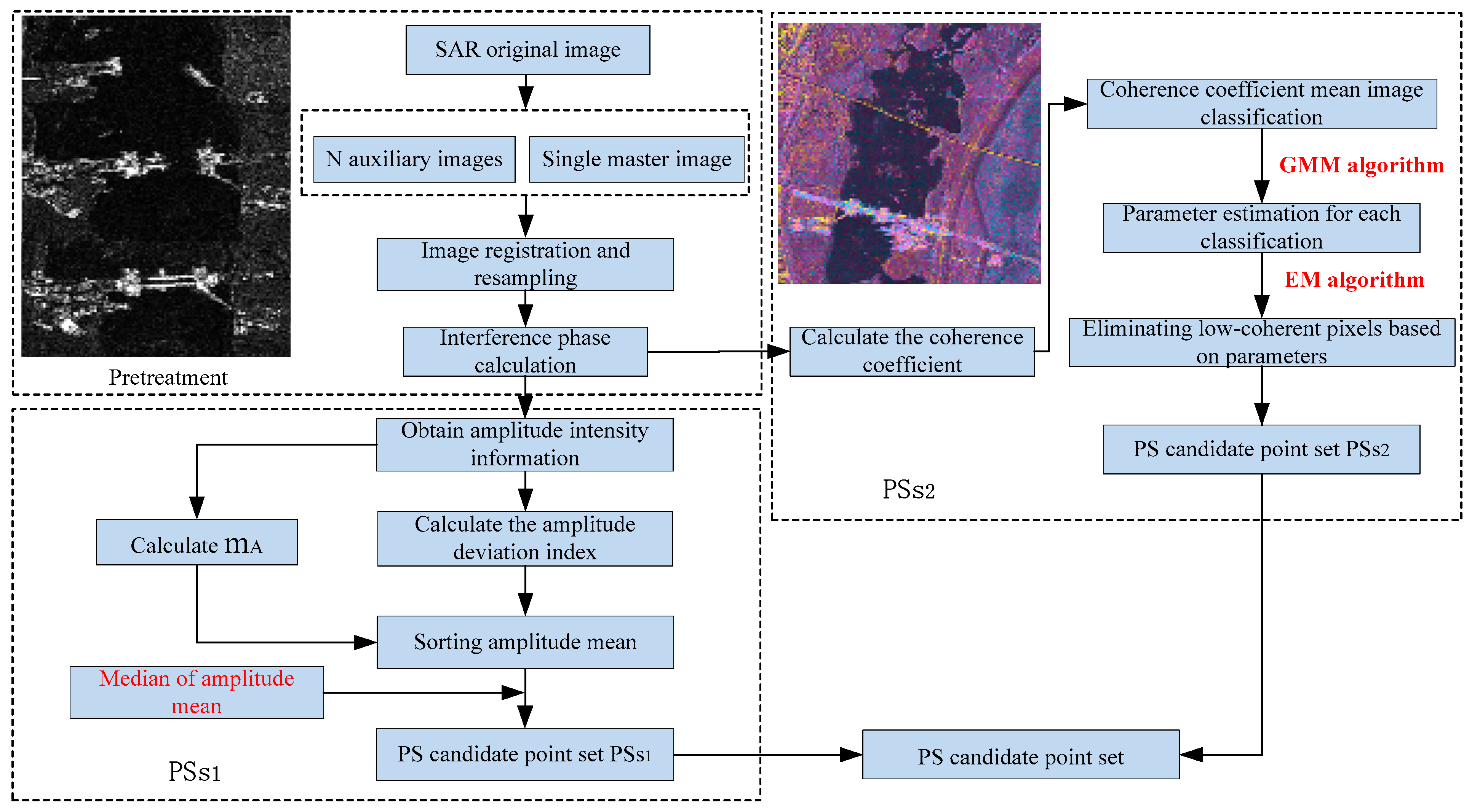
It is challenging to identify PS points in sea-crossing bridges during construction through traditional PS point selection methods due to temporary changes at construction sites. These short-term changes include earthworks, the construction and dismantling of temporary structures, as well as incomplete and unstable bridge surfaces. Hence, this study proposed a PS point selection method integrating statistical theory and GMM-EM algorithm. The time-series SAR images underwent segmentation into master and slave images, followed by image registration and the creation of interferograms. Utilizing the amplitude dispersion index threshold method, an amplitude value and amplitude dispersion index were determined before the derivation of a candidate PS points set through primary and secondary screening based on amplitude information as an incoherence evaluation indicator. The coherence coefficient threshold method was then used to compute the mean values of the coherence coefficient and temporal coherence coefficient, serving as input samples for GMM-EM classification to acquire a candidate PS points set with temporal coherence as the coherence evaluation indicator. Finally, the two candidate PS points sets were merged as the ultimate PS points set through a set-based approach [17,18,19,20]. The detailed methodology is illustrated in Figure 2.

2.3.1. PS Point Selection Based on Statistical Theory

Relying solely on the amplitude dispersion index threshold method in PS points target recognition may overlook point targets with low scattering intensity and relative stability (e.g., points on water surfaces), potentially leading to erroneous selections [21,22]. Given that threshold selection is often guided by empirical knowledge, the judicious selection of thresholds holds paramount importance in practical applications. Therefore, this study advocated a dual-threshold selection method—combining the amplitude dispersion index with the statistical median of the amplitude mean as the initial stage of PS points target recognition. First, the amplitude dispersion index method computed the amplitude dispersion value to establish a reasonable initial threshold. The secondary screening was conducted on the retained PS points based on the initial threshold, whereby the amplitude mean values of point targets were sorted, with the median of the mean value sequence serving as the threshold. Point targets surpassing this threshold were used as the PS candidate point set for the first segment of incoherence evaluation indicators. The median is not sensitive to extreme values, ensuring stability in the presence of outliers and eliminating erroneous points.
Under this approach, the stability of a candidate point was measured using an amplitude deviation index. Points showing such stability were designated as PS candidate points, followed by secondary identification of the scattering intensity of PS candidate points based on stability. Therefore, this method not only considered the stability of PS points across long time series images but also adopted statistical methods to analyze amplitude distribution across all images. This achieved the dual objective of retaining effective points and eliminating non-effective ones, thus facilitating the optimal selection of PS point targets in the first step.

2.3.2. PS Point Selection Based on GMM-EM Algorithm

The conventional coherence threshold PS point selection method filters out pixels with significant decorrelation. However, this method relies on manual threshold setting. It is also susceptible to data distribution variations, with poor adaptability to diverse scenes and data characteristics [23,24]. Thus, this study used the GMM-EM algorithm to identify PS points based on the coherence coefficient attribute, which is the second aspect of PS point identification [15,16]. In this method, temporal coherence served as the coherence indicator, with the GMM algorithm used to depict pixel distribution in the mean coherence coefficient image, thereby obtaining homogeneous coherence areas. Moreover, the EM algorithm determined normal distribution parameters for each coherence pixel type, eliminating pixels in low coherence areas while retaining those in high coherence areas [16]. This method comprised two processes:
(1)
To attain a homogeneous coherent area, N + 1 time-series SAR images were divided into a master image and N slave images, yielding N interference image pairs. The coherence coefficient (γ) of each pixel in the interference image pairs is expressed as follows:
γ = i = 1 m j = 1 n S 1 i , j S 2 * i , j i = 1 m j = 1 n S 1 i , j 2 i = 1 m j = 1 n S 2 i , j 2
where S1 and S2 represent complex blocks of local pixel information from two SAR images constituting an interference pair, * denotes the complex conjugate operator, and m and n denote the size of a local moving window.
The time sequence of the coherence coefficient for each pixel in the image overlap area is γ1, γ2, …, γN, with the average coherence coefficient time sequence value for each pixel denoted as   γ ¯ .
γ ¯ = 1 N i = 1 N γ i
Pixels in the mean coherence coefficient image were categorized into three groups: low, medium, and high. The joint probability density distribution of these pixels is represented as p γ d ¯ :
p γ d ¯ = p ω 0 p γ d ¯ ω 0 + p ω 1 p γ d ¯ ω 1 + p ω 2 p γ d ¯ ω 2
where γ d ¯   signifies the temporal mean value of the coherence coefficient for each pixel in the mean coherence coefficient image, ω0, ω1, and ω2 represent prior probability parameters for pixels in low, medium, and high mean coherence coefficient images, respectively. The mathematical expression for N classes p γ d ¯ across all pixels is:
p γ d ¯ = n = 1 N p n p γ d ¯ n
where p γ d ¯ n denotes the probability density distribution feature of a specific component of the mean coherence coefficient image, and p(n) represents the prior probability of the component in the Gaussian mixture model.
If the components in the mean coherence coefficient image follow a normal distribution [25,26], then
p γ d ¯ n = 1 2 π σ n 2 e x p γ d ¯ μ n γ d ¯ μ n T 2 σ n 2
where μ n and σ n 2 represent the mean and variance of a class in the mean coherence coefficient image, and the pixels of the class adhere to the following relationship:
i = 1 V j = 1 W p γ d ¯ i , j n = 1
where the prior probability of each component in the mean coherence image satisfies n = 1 N p n = 1 , and 0 p n 1 .
(2)
To eliminate pixels in the low coherence area while retaining those in the high coherence area, this study derived initialization parameters Ø(0) for low, medium, and high mixed components based on the distribution characteristics of the coherence coefficient in the mean coherence coefficient image. Subsequently, the posterior probability p n   of each component was calculated by adding the probabilities of the three components across all pixels. The optimal solution for each parameter was obtained iteratively using the EM algorithm. The process is as follows:
Parameter initialization
The mean image was classified according to pixels with varying levels of coherence coefficients in the coherence coefficient mean image. The mean value   μ 0 , variance σ 0 2 , and probability of each class of pixels across the entire image were determined to obtain initialization parameters.
Parameter estimation
Considering γ d ¯ as the input value for the GMM-EM algorithm, each γ d ¯ is traversed, yielding the probability value Y d = γ d ¯ , Z for all pixels, where Z n corresponds to the distribution dimension of pixels in the mean image of the coherence coefficient. The log-likelihood function Y d for each pixel in the mean image of the coherence coefficient in the study area is computed as follows:
log p γ d ¯ = i , j n = 1 N Z n i , j log p n p γ d ¯ i , j θ n
where Z n i , j represents the probability of each pixel:
Z n i , j = p n γ d ¯ i , j , t = p n p γ d ¯ i , j θ n m = 1 N p m p γ d ¯ i , j θ n t
where t represents the number of iterations in the EM algorithm solving process, and t signifies the parameter value corresponding to the tth iteration.
Parameter maximization
The parameter values maximizing the likelihood function were determined through an iterative solution:
Positive factors:
p n t + 1 = 1 N i , j Z n i , j
  μ n t + 1 = i , j Z n i , j γ d ¯ i , j i , j Z n i , j
σ n 2 t + 1 = i , j Z n i , j γ d ¯ i , j μ n t + 1 γ d ¯ i , j μ n t + 1 T i , j Z n i , j

2.3.3. PS Point Selection Based on Statistical Theory and GMM-EM Algorithm

In the context of constructing cross-sea bridges, the traditional PS point selection method is not ideal due to the bridge’s low scattering intensity caused by environmental instability and partial decoherence of the bridge. Consequently, identifying sufficient and reliable PS points is challenging and hinders the monitoring process. This study addressed this issue by leveraging statistical characteristics of backscatter signals, such as average amplitude and amplitude dispersion, from time series SAR images as incoherence evaluation indices. Screening of the statistical median of the amplitude dispersion index and amplitude average value twice enabled the extraction of a set of PS points exhibiting stable backscatter over time. Simultaneously, temporal coherence served as the coherence index. Using the GMM algorithm, the distribution of pixel points in the coherence coefficient image was represented to delineate homogeneous coherence areas [27,28]. The EM algorithm was then applied to obtain the normal distribution parameters of each coherent class, facilitating the removal of interfering low-coherence pixel points, while maximizing the retention of PS points in high-coherence areas [29]. Combining these two sets of PS candidate point sets enhanced SAR image interpretation, improving the quantity and quality of recognized PS points on the under-construction cross-sea bridge.
The PS point selection process based on statistical theory and the GMM-EM algorithm is as follows:
(1)
Amplitude values and amplitude dispersion indices were computed based on the amplitude images of the study area. A threshold for the amplitude dispersion index was established to conduct the initial screening of PS points. The amplitude average of the initially screened PS candidate points was then sorted, with the median of this sequence chosen as the threshold for the second screening. The candidate points obtained at this stage are denoted as PSS1.
(2)
Using the GMM-EM algorithm, coherence coefficients of ground scattering units were statistically analyzed and classified to extract coherence coefficient features of interferometric pairs. High-coherence pixel points were selected based on the Gaussian parameters of each category of pixel points. The candidate points acquired in this phase are referred to as PSS2.
(3)
PSS1 and PSS2 were merged using set theory, providing the foundation for subsequent calculations and establishing the components of the interferometric phase. The deformation phase was inverted, thereby yielding deformation information for the study area.

3. Results

3.1. Analysis of PS Point Identification Results

3.1.1. Analysis of PS Point Identification Results Based on Statistical Theory

For a comprehensive comparison of PS point identification methods, this study conducted three sets of experiments: the statistical theory-based PS point selection method that used the amplitude dispersion index and statistical median, the GMM-EM method, and the method proposed in this study. PS point identification was executed using MATLAB software in this study.
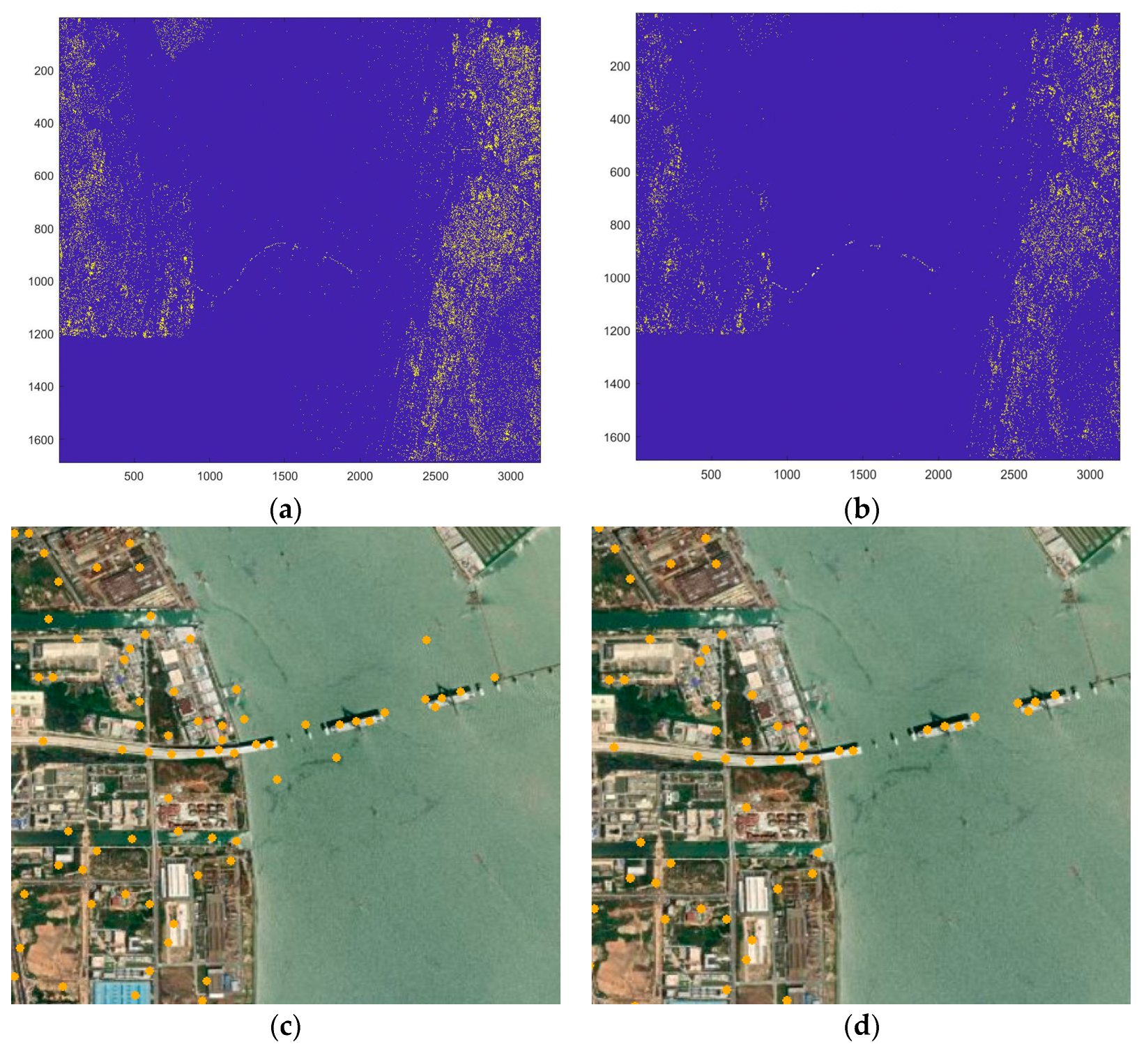
In the experiment using the amplitude dispersion index for the initial screening of PS point targets in the study area, a threshold value of DA1 = 0.75 was selected. Figure 3 shows the distribution results of PS point targets. Specifically, Figure 3a illustrates the initial screening outcomes based on the amplitude dispersion threshold, while Figure 3c provides an enlarged view of these results, highlighting details of the initial screening process. As observed in Figure 3a, numerous PS point targets are predominantly situated in residential areas flanking the sea-crossing bridge under construction, as well as along roads and bridges. However, some noise signals and points on the water surface are erroneously identified as PS points. In terms of secondary identification, points with amplitude dispersion index values DA1 < 0.75 are retained for statistical computation of the average amplitude. They are subsequently sorted from smallest to largest, and the median of this sequence (0.52) is selected as the threshold DA2. PS points with DA2 ≤ 0.52 are retained as candidate points (PSs1). Figure 3b shows the secondary screening results based on the statistical median of amplitude values, with Figure 3d offering an enlarged view of these outcomes. As evident in Figure 3b,d, erroneous points, such as those on the sea surface and bridge shadows, are eliminated after secondary identification based on the median.

3.1.2. Analysis of PS Point Identification Results Based on GMM-EM Method

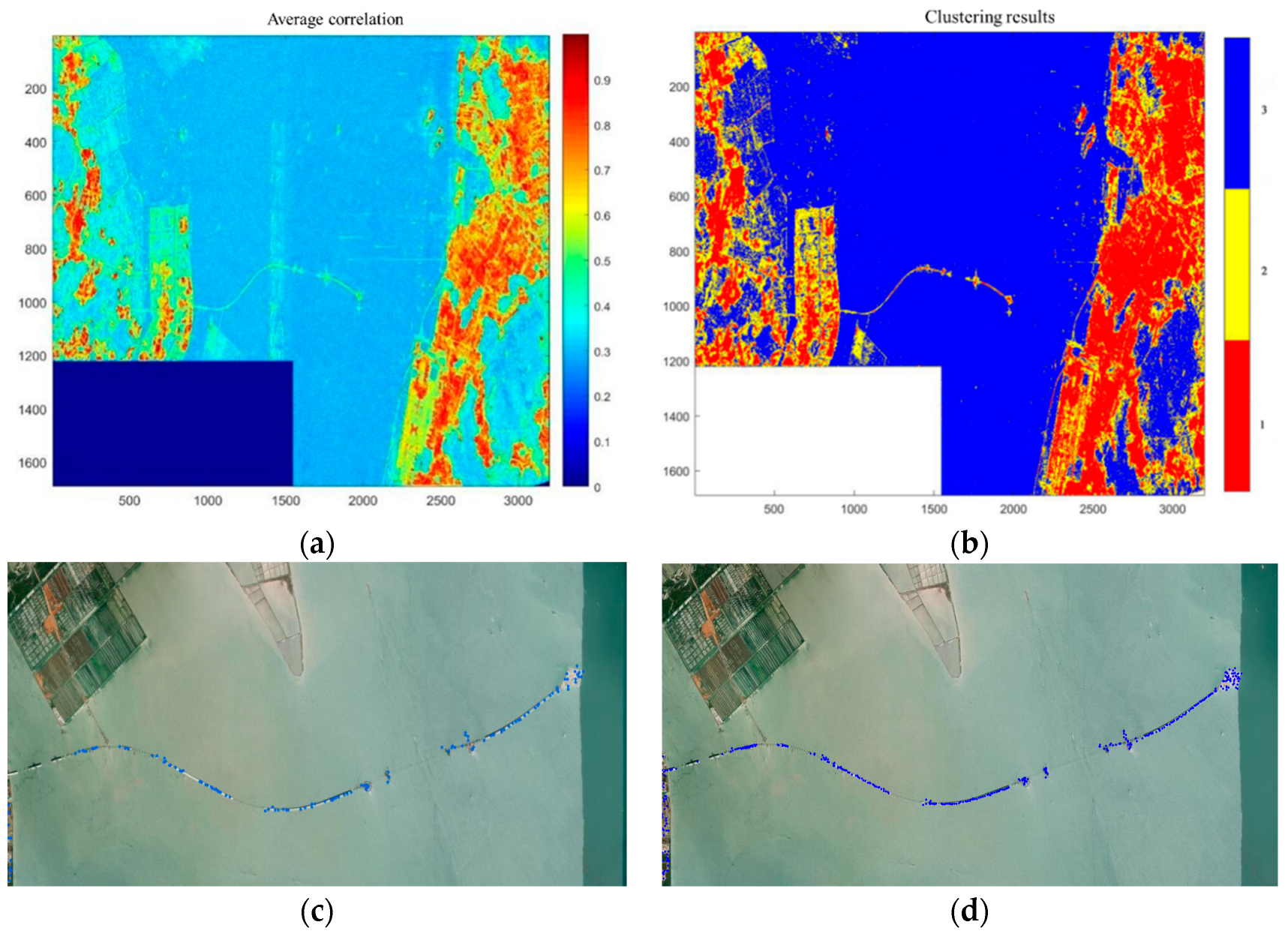
The coherence information of the study area images was used to calculate the average temporal coherence coefficient for each pixel. Statistical analysis revealed a coherence coefficient range from 0.32 to 0.96 across the study area, encompassing a total of 4,681,640 pixel points. Figure 4 illustrates the distribution of PS point targets, with low-coherence areas primarily comprising the sea, surrounding bridges with urban green spaces, and vegetation regions. Figure 4a displays the average coherence coefficient map, indicating extensive low-coherence areas due to the cross-sea bridge construction, with coherence coefficients predominantly ranging from 0.35 to 0.42. Scatterers with coherence coefficients surpassing 0.6 are concentrated on the bridge construction site, traffic roads on the east and west sides of the study area, buildings, and residential zones, along with various surface features characterized by artificial structures and urban greenery.
For PS point identification using the GMM-EM method, pixels in the coherence coefficient mean image were classified into three classes based on their coherence coefficient distribution. It was observed that 1,578,650 pixels fell in the 0.32 to 0.6 range, 1,034,326 pixels in 0.6 to 0.85, and 2,068,664 pixels in 0.85 to 0.96. Figure 4b shows the clustering results of coherence coefficient distribution for each Gaussian parameter class obtained after EM algorithm computation. Class 3, representing the low-coherence pixel set, was excluded, while the remaining classes constituted the PS candidate point set, PSS2. The retained pixels after GMM-EM computation suggested a significant correlation with areas of high scattering performance in both PS points and SAR image intensity maps.
Figure 4c provides an enlarged view of the bridge section detailing PS point identification using a coherence threshold set at 0.52. Conversely, Figure 4d presents the PS points identified using the GMM-EM algorithm. A comparative analysis between the two figures reveals that PS points covered most of the completed bridge structures. However, challenges remained in identifying valid PS points at the Zhongshan Bridge due to lower coherence from construction activities. Notably, the GMM-EM algorithm resulted in a higher density of identified PS points compared to traditional coherence thresholding methods, particularly in areas such as non-navigable bridge openings, the main towers of the Lingdingyang Bridge, and the west artificial island area. This comprehensive coverage across various locations of the Shenzhen-Zhongshan Cross-Sea Bridge lays the groundwork for a refined analysis of its deformation characteristics.

3.1.3. Analysis of PS Point Identification Results Based on Statistical Theory and GMM-EM Method

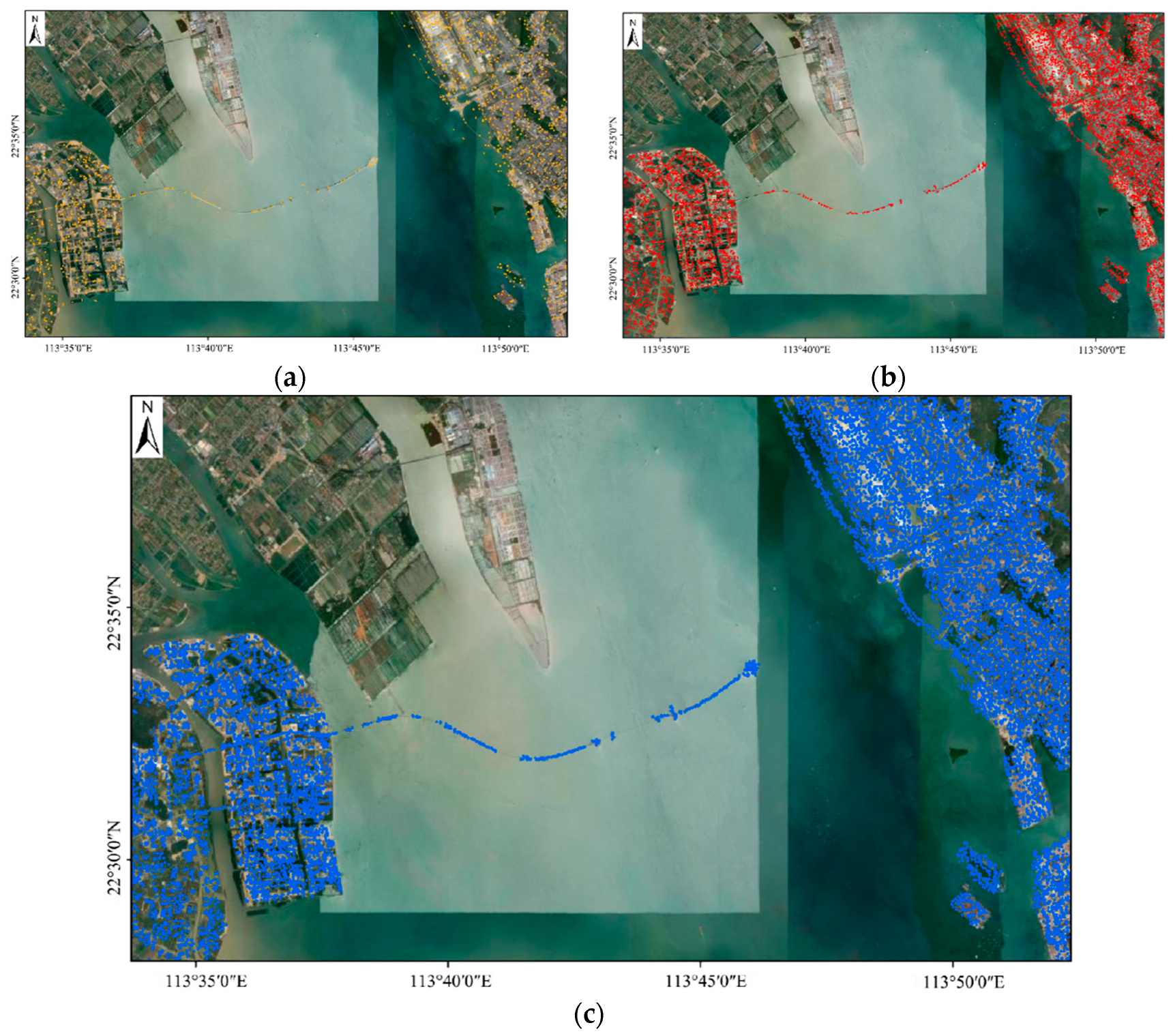
Figure 5 illustrates the outcomes of two traditional PS point identification methods, alongside the results of the method integrating statistical theory and GMM-EM. Specifically, Figure 5a shows the outcomes of the amplitude dispersion index method, while Figure 5b demonstrates the results of the coherence coefficient threshold method. In contrast, Figure 5c presents the findings of the method proposed in this study. Our method amalgamated the strengths of amplitude dispersion stability and temporal coherence to identify PS points that not only cover the majority of completed areas of the Shenzhen-Zhongshan Cross-Sea Bridge but also showed a more evenly distributed pattern that eliminated water shadows, noise, and other erroneous points. Statistical analysis revealed that the amplitude dispersion index method identified a total of 10,096 PS point targets in the study area, with 1078 PS points situated in the Shenzhen-Zhongshan Channel and the west artificial island. In comparison, the coherence coefficient threshold method identified 28,590 PS point targets in the study area, including 2342 PS points in the Shenzhen-Zhongshan Channel and the west artificial island. Conversely, our method identified a total of 34,456 PS point targets in the study area, with 3020 PS points located in the Shenzhen-Zhongshan Channel and the west artificial island. This represents a nearly twofold increase in identified PS points compared to the amplitude dispersion index method and a 29% rise compared to the coherence coefficient threshold method, thereby providing robust assurance for subsequent bridge deformation analysis.
The method proposed in this study leverages the advantages of the amplitude dispersion index and median dual-threshold screening of amplitude mean, mitigating noise and clutter to significantly enhance the accuracy of PS point identification, particularly in complex sea-crossing environments that require stable scatterers detection. As a clustering method based on the inherent distribution characteristics of the data, the GMM-EM algorithm relies less on preset parameters compared with simple thresholding methods. Therefore, our proposed method is highly suitable for identifying PS points in cross-sea bridge construction, demonstrating versatility and applicability. Furthermore, GMM-EM can adapt to variations in SAR image coherence caused by factors such as ocean tides and aquatic environment changes, thereby enhancing identification stability. By integrating the advantages of statistical theory and the GMM-EM method, the proposed approach mitigates uncertainties associated with methodology limitations and improves the consistency of PS point identification. This, in turn, facilitates a comprehensive and accurate assessment of sea-crossing bridge deformation, enabling real-time monitoring and a better understanding of bridge structure stability.

3.2. Deformation Analysis of Under-Construction Cross-Sea Bridges and Adjacent Engineering Areas

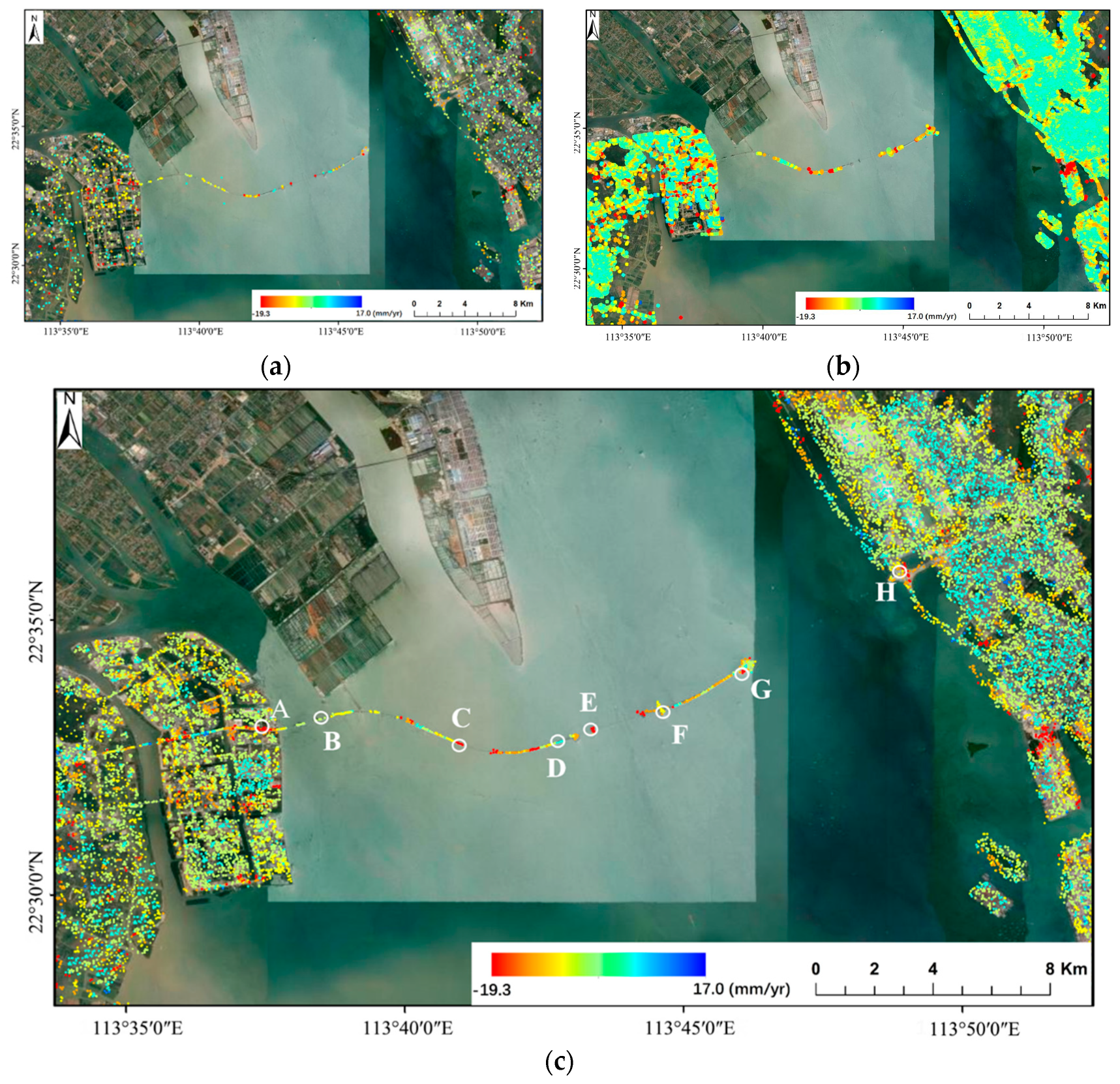
Figure 6 presents a comparison of deformation rates in the sea-crossing bridge and its surrounding areas using three distinct methods. Specifically, Figure 6a illustrates the deformation rate map obtained through traditional PS-InSAR, while Figure 6b depicts the deformation rate map acquired through Small Baseline Subset InSAR (SBAS-InSAR). Figure 6c shows the deformation rate map derived from the method proposed in this study. From Figure 6, it is evident that the PS points obtained through our enhanced method offer dense coverage of deformation monitoring outcomes in the Shenzhen-Zhongshan Cross-Sea Bridge and its environs. This facilitates the identification of deformation patterns in areas that are challenging to monitor using traditional PS-InSAR and SBAS-InSAR, such as the area labeled as Point B in Figure 6c.
As illustrated in Figure 6c, the Shenzhen-Zhongshan Cross-Sea Bridge area remained relatively stable during the monitoring period from December 2021 to May 2023, with deformation rates ranging from −19.3 mm/yr to 17 mm/yr. In the western Cuiheng New Area of the bridge, most areas showed deformation rates varying from −5 mm/yr to 5 mm/yr, with minor subsidence detected in central and southern sections, where deformation rates ranged from −10 mm/yr to −8 mm/yr. Conversely, a slight uplift was noted in some eastern areas of the bridge, with deformation rates ranging from 4 mm/yr to 6 mm/yr. Furthermore, a significant subsidence area was identified at the intersection of roads in the Qianhai New Area, with the maximum rate recorded at −17.6 mm/yr.
The construction section of the bridge in Zhongshan showed overall stability, with deformation rates ranging from −5 mm/yr to 0 mm/yr. However, pronounced subsidence was observed at the junction of the Cuiheng New Area and sea bridge, with varying deformation rates from −18 mm/yr to −15 mm/yr. The midsection of the non-navigable span bridge connecting the Zhongshan and Lingdingyang construction sections showed signs of subsidence, with deformation rates ranging from −18.5 mm/yr to −16 mm/yr. Affected by construction activities, Lingdingyang Bridge experienced more severe subsidence, with deformation rates ranging from −13 mm/yr to −8 mm/yr at the main tower and slightly higher rates of −19 mm/yr to −17 mm/yr at the main part of the bridge. The non-navigable span between Lingdingyang Bridge and the west artificial island experienced varying subsidence rates from −15 mm/yr to −13 mm/yr. The west artificial island remained relatively stable overall, with significant subsidence only at the intersection of the bridge, where deformation rates reached −16 mm/yr. Conversely, there were varying degrees of subsidence on the east artificial island, with deformation rates ranging from −19.3 mm/yr to −13 mm/yr.
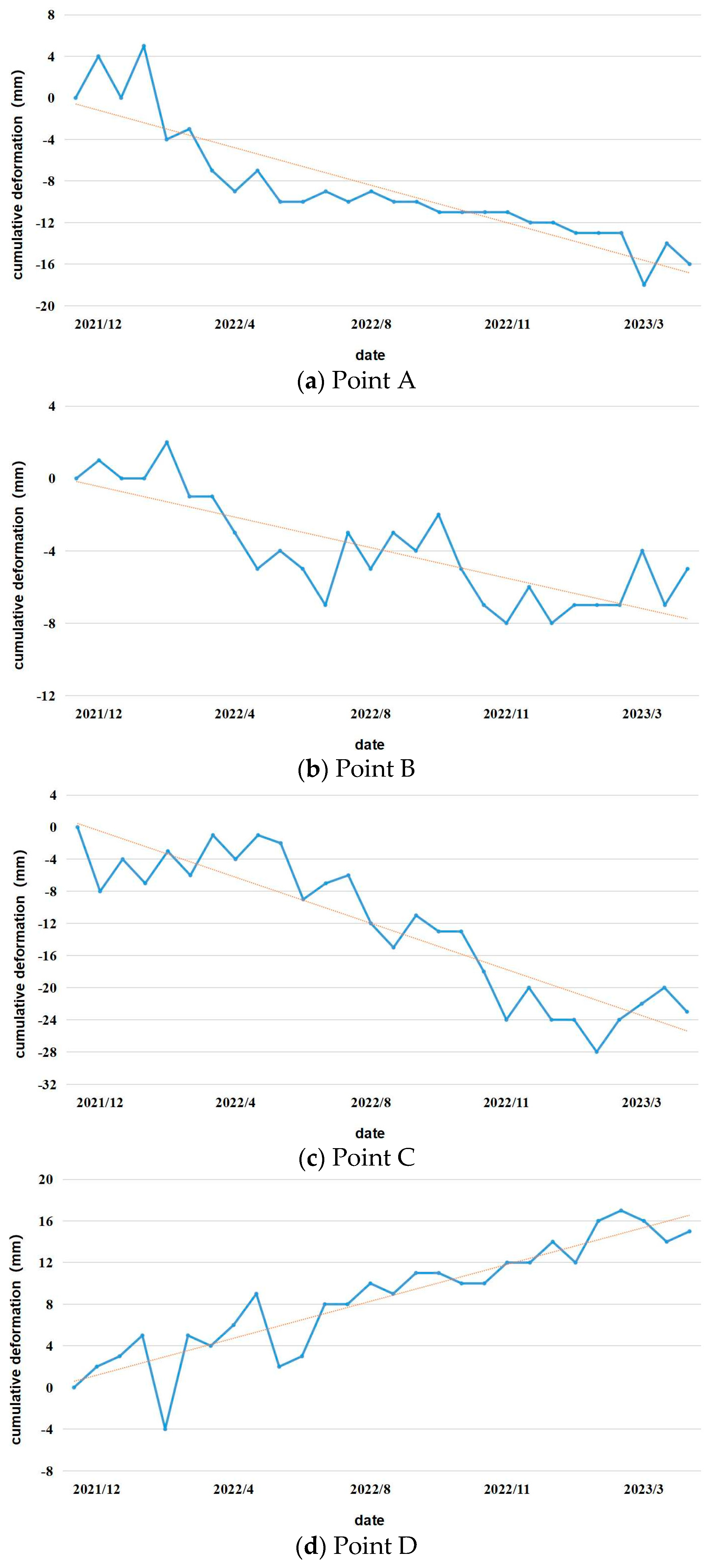
Eight feature points (A–H) strategically positioned at diverse locations were selected in this study to examine the distinctive deformation characteristics of the under-construction cross-sea bridge and its adjacent engineering areas. Points B, C, D, E, and F represent pivotal deformation zones of the bridge, while Points A, G, and H signify ground deformation zones. The precise locations of these monitoring points are delineated in Figure 6c. Point A marks the juncture of the ground and sea bridge of the Shenzhen-Zhongshan Cross-Sea Bridge, while Point B is positioned along the construction section in Zhongshan. Point C is located on the non-navigable span bridge, and Point D is located at the west anchorage area of the non-navigable span bridge and Lingdingyang Bridge. Meanwhile, Point E is situated in the main tower area of Lingdingyang Bridge, and Point F is located in the east anchorage area of Lingdingyang Bridge. Point G is positioned at the intersection of the west artificial island and bridge, while Point H is located on the east artificial island. The time-series deformation results of each point are illustrated in Figure 7, where the blue lines depict the respective time-series monitoring values, and the orange dashed lines represent the fitted lines of the deformation variables for each point during the monitoring period. Throughout nearly eighteen months of continuous monitoring, all points except Point D showed an uplift with varying degrees of subsidence deformation. The cumulative deformation variables from Points A to H tallied to −16 mm, −5 mm, −23 mm, 15 mm, −21 mm, −13 mm, −32 mm, and −20 mm, respectively. Points A, G, and H, situated on the ground, and Point F, positioned in the anchorage area, demonstrated a linear subsidence trend. Conversely, Points B, C, D, and E, situated at different locales on the bridge, experienced substantial deformation fluctuations—an indirect indication of elastic deformation on the bridge, which is susceptible to the impact of unstable construction environments.

4. Discussion

4.1. Comparative Analysis of Results

With the absence of external monitoring data during the study period in the study area, comparative experiments were conducted using the traditional PS-InSAR method, SBAS-InSAR technique, and this study’s proposed method to validate the accuracy of the latter method [30,31,32]. The line-of-sight (LOS) deformation rate results are depicted in Figure 6.
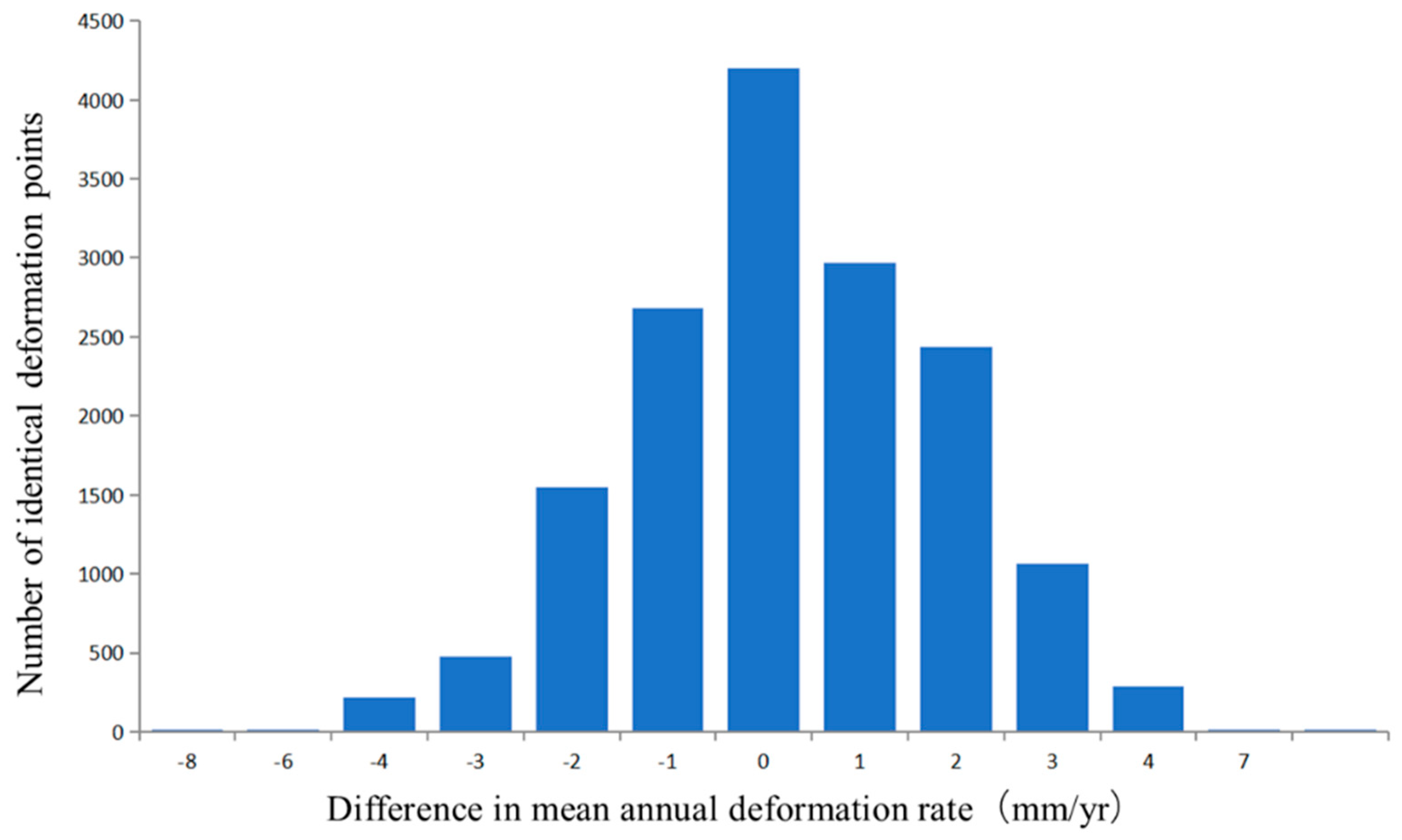
Upon comparative analysis, it was observed that the monitoring results of the three methods were generally consistent in subsidence magnitude and distribution. To mitigate randomness, approximately 15,000 common deformation points with identical geographic coordinates were extracted for differencing. As illustrated in Figure 8, an internal accuracy assessment of the monitoring results was performed by calculating the LOS annual average deformation rate differences of the common deformation points. The absolute values of the annual average deformation rate differences for most common deformation points were less than 5 mm/yr, with most of the deformation differences falling in the range of [−3 mm/yr, 3 mm/yr]. The calculated standard deviation of the differences was 1.32 mm/yr. The results indicated high internal accuracy in the deformation monitoring of the Shenzhen-Zhongshan Bridge and its surrounding areas. To further validate the rationality and reliability of the proposed method, external monitoring data collection and external verification experiments are necessary to ensure bridge safety in the future.

4.2. Analysis of Deformation Causes

The results showed subsidence deformation at Point A, situated at the juncture of land and the starting point of the sea bridge. This deformation can be attributed to disparities in underground soil layers and uneven foundations at the intersection. On the other hand, the subsidence deformations at Points B and C were due to disparities in seabed layers and soil characteristics, leading to uneven settling of bridge piers. As a result of marine environmental factors such as salt content and tides, the corrosion of bridge structures and foundation materials might have also affected foundation stability. In terms of the uplift deformation observed at point D, analysis suggests its location at the boundary between the non-navigable span bridge and Lingdingyang Bridge—a suspension bridge—could have contributed to uplift tendencies at both ends due to the bending of the main bridge structure under load, resulting in a concave shape of the bridge deck in the middle [33]. Although the construction of the bridge was not completed during the study period, activities such as worker movements and transport of materials could exert pressure on the bridge structure, leading to deformation. The subsidence deformation at Point E can be attributed to issues such as uneven concrete pouring and insufficient soil backfilling during the construction of the main tower. The subsidence deformation of Point F might have resulted from the construction process of the Lingdingyang Bridge’s east and west anchorages. This necessitated the formation of artificial islands in the sea using steel cylinders, and the construction of anchorages on these islands to secure the suspension bridge, leading to subsidence deformation. Points G and H are situated on the east and west artificial islands, respectively. The deformation causes were compared with those of the artificial islands at the Hong Kong-Zhuhai-Macao Bridge. The subsidence deformations at these points can be attributed to the installation of concrete structures to protect the islands from wave erosion. Submerged in seawater for prolonged periods, such structures may become heavier because of attachment by marine organisms and microorganisms, resulting in subsidence [11].
The results revealed the heterogeneous nature of deformation occurring at different points along the under-construction cross-sea bridge. This variety of deformation sources poses significant challenges to the progress of bridge construction, emphasizing the need for timely understanding and management of deformation at various locations to ensure the bridge’s stable construction and future operational reliability. Furthermore, special attention must be directed towards critical areas such as main towers, anchorages, and other areas prone to deformation during the operational phase of the bridge.

5. Conclusions

This study presented a PS point selection method incorporating statistical theory and the GMM-EM algorithm to address the issue of PS point selection for cross-sea bridges being built in unstable environments. The proposed method was empirically validated on the Shenzhen-Zhongshan Bridge in China’s Guangdong province. The conclusions of this work are as follows: (1) Compared with existing methods, the proposed method significantly increased the number of identified PS points on the cross-sea bridge by nearly 100% compared to the amplitude dispersion index threshold method and 29% compared to the coherence coefficient threshold method. The results demonstrated that the proposed PS point selection method can improve the density and reliability of PS points for cross-sea bridges under construction. (2) In the study area of Shenzhen-Zhongshan Bridge, the section under construction in Zhongshan showed relative stability, while other areas experienced varying degrees of subsidence deformation. Furthermore, the Shenzhen-Zhongshan Bridge underwent elastic deformation during the construction period.
Although the improved algorithm can enhance the accuracy and density of PS point identification, it is time consuming and applicable to relatively small datasets. Future improvements should focus on the algorithm’s operational efficiency.

Author Contributions

Conceptualization, J.L., X.Z., Z.X., W.M. and S.H.; methodology, J.L., X.Z., Z.X., W.M. and S.H.; writing—original draft preparation, J.L., X.Z., Z.X., W.M. and S.H.; data curation, J.L., X.Z. and Z.X.; visualization, X.Z. and W.M.; supervision, X.Z. and W.M.; writing—reviewing and editing, J.L., X.Z., Z.X., W.M. and S.H. All authors have read and agreed to the published version of the manuscript.

Funding

This research was funded by the CHINA-ASEAN Earthquake Disaster Monitoring and Defense Capability Improvement Project (NO. 12499901) and Beijing Key Laboratory of Urban Spatial Information Engineering (NO. 20230101).

Institutional Review Board Statement

Not applicable.

Informed Consent Statement

Not applicable.

Data Availability Statement

Sentinel data were made available by ESA in the Copernicus project through the Open Access Hub portal (https://scihub.copernicus.eu/dhus/#/home (accessed on 25 May 2022)).

Acknowledgments

We would like to thank the reviewers for their constructive and detailed comments.

Conflicts of Interest

The authors declare no conflicts of interest.

References

  1. Yu, H.H.; Li, B.Q.; Xiao, Y.; Sun, J.Y.; Chen, C.; Jin, G.Y.; Liu, Y.Y. Surface Subsidence over a Coastal City Using SBAS-InSAR with Sentinel-1A Data: A Case of Nansha District, China. Remote Sens. 2023, 16, 55. [Google Scholar] [CrossRef]
  2. Lubczynski, M.W.; Leblanc, M.; Batelaan, O. Remote sensing and hydrogeophysics give a new impetus to integrated hydrological models: A review. J. Hydrol. 2024, 633, 130901. [Google Scholar] [CrossRef]
  3. Tonelli, D.; Caspani, V.F.; Valentini, A.; et a Rocca, A.; Torboli, R.; Vitti, A.; Perissin, D.; Zonta, D. Interpretation of Bridge Health Monitoring Data from Satellite InSAR Technology. Remote Sens. 2023, 15, 5242. [Google Scholar] [CrossRef]
  4. He, Y.; Chen, Y.; Wang, W.; Yan, H.; Zhang, L.; Liu, T. TS-InSAR analysis for monitoring ground deformation in Lanzhou New District, the loess Plateau of China, from 2017 to 2019. Adv. Space Res. 2021, 67, 1267–1283. [Google Scholar] [CrossRef]
  5. Lazecky, M.; Hlavacova, I.; Bakon, M.; Sousa, J.J.; Perissin, D.; Patricio, G. Bridge displacements monitoring using space-borne X-band SAR interferometry. IEEE J. Sel. Top. Appl. Earth Obs. Remote Sens. 2016, 10, 205–210. [Google Scholar] [CrossRef]
  6. D’Amico, F.; Gagliardi, V.; Ciampoli, L.B.; Tosti, F. Integration of InSAR and GPR techniques for monitoring transition areas in railway bridges. NDT E Int. 2020, 115, 102291. [Google Scholar] [CrossRef]
  7. Schlögl, M.; Widhalm, B.; Avian, M. Comprehensive time-series analysis of bridge deformation using differential satellite radar interferometry based on Sentinel-1. ISPRS J. Photogramm. Remote Sens. 2021, 172, 132–146. [Google Scholar] [CrossRef]
  8. Wang, H.; Li, A.; Li, J. Progressive finite element model calibration of a long-span suspension bridge based on ambient vibration and static measurements. Eng. Struct. 2010, 32, 2546–2556. [Google Scholar] [CrossRef]
  9. Qin, X.; Ding, X.; Liao, M.; Zhang, L.; Wang, C. A bridge-tailored multi-temporal DInSAR approach for remote exploration of deformation characteristics and mechanisms of complexly structured bridges. ISPRS J. Photogramm. Remote Sens. 2019, 156, 27–50. [Google Scholar] [CrossRef]
  10. Qin, X.; Li, Q.; Ding, X.; Xie, L.; Wang, C.; Liao, M.; Zhang, L.; Zhang, B.; Xiong, S. A structure knowledge-synthetic aperture radar interferometry integration method for high-precision deformation monitoring and risk identification of sea-crossing bridges. Int. J. Appl. Earth Obs. Geoinf. 2021, 103, 102476. [Google Scholar] [CrossRef]
  11. Xiong, S.; Wang, C.; Qin, X.; Zhang, B.; Li, Q. Time-Series Analysis on Persistent Scatter-Interferometric Synthetic Aperture Radar (PS-InSAR) Derived Displacements of the Hong Kong–Zhuhai–Macao Bridge (HZMB) from Sentinel-1A Observations. Remote Sens. 2021, 13, 546. [Google Scholar] [CrossRef]
  12. Hoppe, E.J.; Novali, F.; Rucci, A.; Fumagalli, A.; Del Conte, S.; Falorni, G.; Toro, N. Deformation monitoring of posttensioned bridges using high-resolution satellite remote sensing. J. Bridge Eng. 2019, 24, 04019115. [Google Scholar] [CrossRef]
  13. Yang, M.; Wang, R.; Li, M.; Liao, M. A PSI targets characterization approach to interpreting surface displacement signals: A case study of the Shanghai metro tunnels. Remote Sens. Environ. 2022, 280, 113150. [Google Scholar] [CrossRef]
  14. Ma, P.; Liu, Y.; Wang, W.; Lin, H. Optimization of PSInSAR networks with application to TomoSAR for full detection of single and double persistent scatterers. Remote Sens. Lett. 2019, 10, 717–725. [Google Scholar] [CrossRef]
  15. Blekas, K.; Likas, A.; Galatsanos, N.P.; Lagaris, I.E. A spatially constrained mixture model for image segmentation. IEEE Trans. Neural Netw. 2005, 16, 494–498. [Google Scholar] [CrossRef] [PubMed]
  16. Balakrishnan, N.; Leiva, V.; Sanhueza, A.; Vilca, F. Estimation in the Birnbaum-Saunders distribution based on scale-mixture of normals and the EM-algorithm. SORT-Stat. Oper. Res. Trans. 2009, 33, 171–192. [Google Scholar]
  17. Ferretti, A.; Prati, C.; Rocca, F. Permanent scatterers in SAR interferometry. IEEE Trans. Geosci. Remote Sens. 2001, 39, 8–20. [Google Scholar] [CrossRef]
  18. Dong, J.; Zhang, L.; Tang, M.; Liao, M.; Xu, Q.; Gong, J.; Ao, M. Mapping landslide surface displacements with time series SAR interferometry by combining persistent and distributed scatterers: A case study of Jiaju landslide in Danba, China. Remote Sens. Environ. 2018, 205, 180–198. [Google Scholar] [CrossRef]
  19. Falabella, F.; Serio, C.; Masiello, G.; Zhao, Q.; Pepe, A. A Multigrid InSAR Technique for Joint Analyses at Single-Look and Multi-Look Scales. IEEE Geosci. Remote Sens. Lett. 2022, 19, 3086271. [Google Scholar] [CrossRef]
  20. Sousa, J.J.; Hooper, A.J.; Hanssen, R.F.; Bastos, L.C.; Ruiz, A.M. Persistent scatterer InSAR: A comparison of methodologies based on a model of temporal deformation vs. spatial correlation selection criteria. Remote Sens. Environ. 2011, 115, 2652–2663. [Google Scholar] [CrossRef]
  21. Guccione, P.; Zonno, M.; Mascolo, L.; D’Introno, S. Persistent point scatterer statistical analysis for X-band SAR data: The Cosmo-SkyMed case study. Int. J. Remote Sens. 2014, 35, 127–148. [Google Scholar] [CrossRef]
  22. Fan, H.; Liu, Y.; Xu, Y.; Yang, H. Surface subsidence monitoring with an improved distributed scatterer interferometric SAR time series method in a filling mining area. Geocarto Int. 2022, 37, 8979–9001. [Google Scholar] [CrossRef]
  23. Guo, W.; Ke, C.; Fan, Y. Glacier changes on the East Pamirs Plateau: Based on SAR interference data. J. Geo-Inf. Sci. 2019, 21, 1790–1801. [Google Scholar]
  24. Hara, K.; Liu, W.; Yamazaki, F. Monitoring of Volcanic Activity in Kuchinoerabu Island from ALOS-2 Data. J. Remote Sens. Soc. Jpn. 2016, 36, 338–347. [Google Scholar]
  25. Besag, J. On the statistical analysis of dirty pictures. J. R. Stat. Soc. Ser. B Stat. Methodol. 1986, 48, 259–279. [Google Scholar] [CrossRef]
  26. Zheng, M.; Cai, Q.; Qin, M.; Yue, T. A New Approach to Accuracy Assessment of Classifications of Remotely Sensed Data. J. Remote Sens. 2006, 10, 39–48. [Google Scholar]
  27. Wang, P.; Zhu, H.; Ling, X. Intravascular optical coherence tomography image segmentation based on Gaussian mixture model and adaptive fourth-order PDE. Signal Image Video Process. 2020, 14, 29–37. [Google Scholar] [CrossRef]
  28. Tan, W.; Li, J.; Hou, T.; Huang, P.; Qi, Y.; Xu, W.; Chen, Y. A New Permanent Scatterer Selection Method Based on Gaussian Mixture Model for Micro-Deformation Monitoring Radar Images. Sensors 2024, 24, 1809. [Google Scholar] [CrossRef] [PubMed]
  29. Sarker, M.S.; Kamal, A.M.; Rahman, M.Z.; Faruki Fahim, A.K. Land subsidence monitoring using InSAR technique in the southwestern region of Bangladesh. Geomat. Nat. Hazards Risk 2024, 15, 2333795. [Google Scholar] [CrossRef]
  30. Maruo, N.; Susaki, J.; Boonyatee, T.; Kishida, K. Detection of gaps between land and building surface displacement by PSInSAR and SBAS analysis using L-band PALSAR data. In Proceedings of the 2016 IEEE International Geoscience and Remote Sensing Symposium (IGARSS), Beijing, China, 10–15 July 2016; pp. 5994–5997. [Google Scholar]
  31. Yao, J.; Yao, X.; Liu, X. Landslide detection and mapping based on SBAS-InSAR and PS-InSAR: A case study in Gongjue County, Tibet, China. Remote Sens. 2022, 14, 4728. [Google Scholar] [CrossRef]
  32. Zhang, Z.; Hu, C.; Wu, Z.; Zhang, Z.; Yang, S.; Yang, W. Monitoring and analysis of ground subsidence in Shanghai based on PS-InSAR and SBAS-InSAR technologies. Sci. Rep. 2023, 13, 8031. [Google Scholar] [CrossRef] [PubMed]
  33. Dai, X.H.; Yuan, J.Y.; Chen, L.Z.; Huang, Y.L.; Yu, Y.M. Study on the influence of structural form on the displacement response of suspension bridge beam end. Road 2024, 69, 122–130. [Google Scholar]
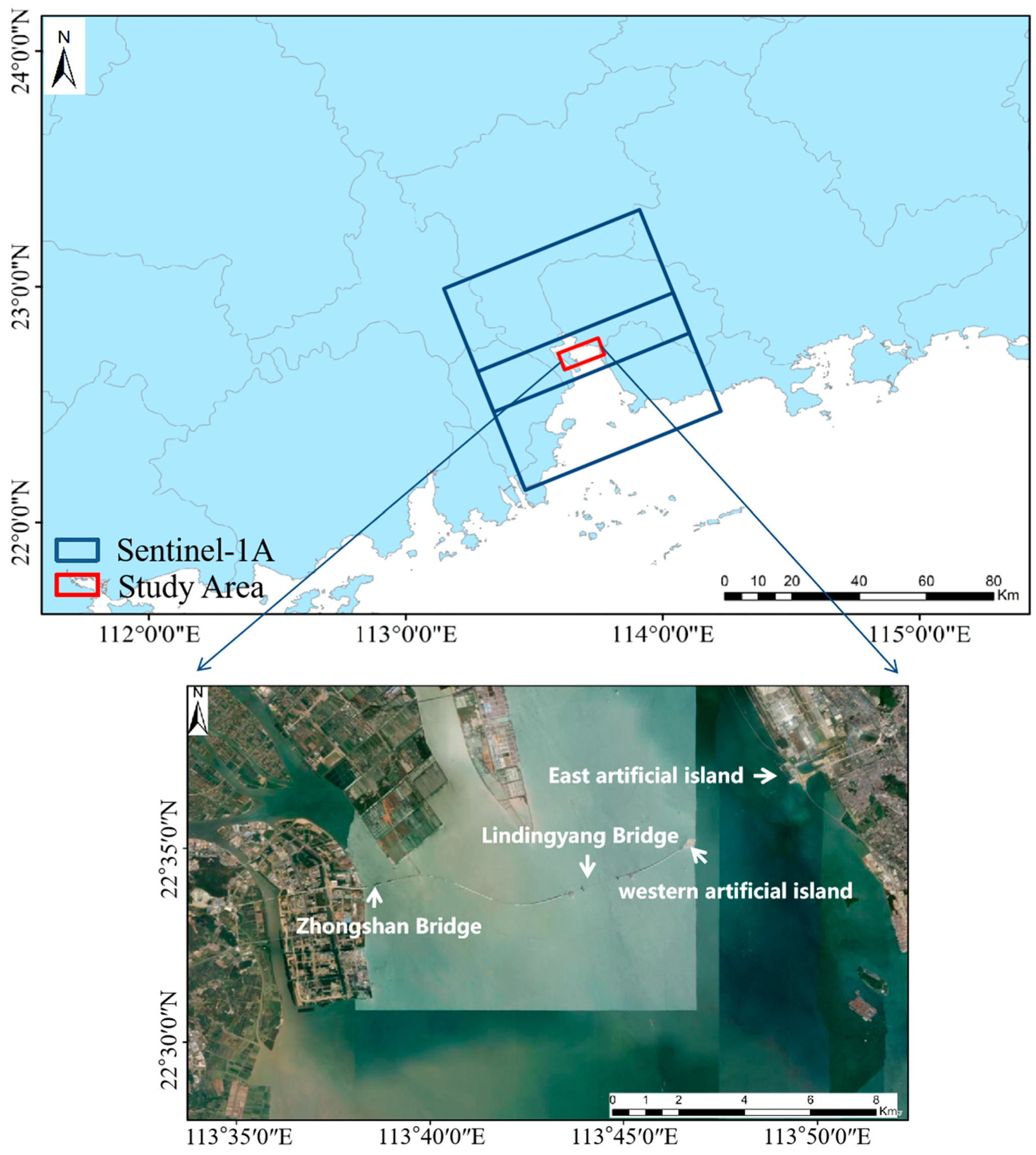
Figure 1. Location of the study area and space coverage of the SAR images.
Remotesensing 16 02197 g001
Figure 2. Technical workflow.
Remotesensing 16 02197 g002
Figure 3. Statistical median of PS point identification results based on the amplitude deviation index and mean of the amplitude. (a) Preliminary screening results of amplitude deviation index; (b) the second screening results of the statistical median of the amplitude mean; (c) preliminary screening details of amplitude deviation index; (d) secondary screening results of the statistical median of the mean amplitude.
Remotesensing 16 02197 g003
Figure 4. Identification results for coherent PS points based on the GMM-EM algorithm. (a) Average coherence coefficient results; (b) coherence clustering results of GMM-EM algorithm; (c) PS points details identified by coherence coefficient threshold method; (d) details of PS points identified by GMM-EM algorithm.
Remotesensing 16 02197 g004
Figure 5. Comparison of the identification results for three PS points. (a) The amplitude dispersion index method; (b) the coherence coefficient threshold method; (c) the proposed method.
Remotesensing 16 02197 g005
Figure 6. Comparison of the deformation rate map between the under-construction bridge and the surrounding area. (a) Traditional PS-InSAR deformation rate map; (b) SBAS-InSAR deformation rate map; (c) the deformation rate map of the proposed method (A–H represent selected typical feature points).
Remotesensing 16 02197 g006
Figure 7. Temporal evolution of deformation at key points in the under-construction cross-sea bridge.
Remotesensing 16 02197 g007aRemotesensing 16 02197 g007b
Figure 8. Residual statistical histogram of deformation rate of the under-construction across-sea bridge.
Remotesensing 16 02197 g008
Table 1. Parameters of Sentinel-1A image.
Parameter NameSentinel-1A
BandC
Product typeSLC
Polarization modeVV
Sensor modeIW
Orbital directionAscending orbit
Spatial resolution20 m
Image number28
Date rangeDecember 2021–May 2023
Disclaimer/Publisher’s Note: The statements, opinions and data contained in all publications are solely those of the individual author(s) and contributor(s) and not of MDPI and/or the editor(s). MDPI and/or the editor(s) disclaim responsibility for any injury to people or property resulting from any ideas, methods, instructions or products referred to in the content.