
Studies on High-Resolution Airborne Synthetic Aperture Radar Image Formation with Pseudo-Random Agility of Interpulse Waveform Parameters

Abstract
:1. Introduction
- (1)
- Considering the pseudo-random agility technology of interpulse waveform parameters in SAR, only a single parameter or two parameters, such as pulse width and/or initial phase, was changed in most previous works. The compensation for agile interpulse waveform parameters in SAR imaging processing is relatively easy, but its anti-interference ability for active coherent jamming is limited. The influence of agile interpulse waveform parameters, such as pulse width, chirp rate polarity, initial phase and PRI, on SAR imaging processing and their compensation methods are analyzed in detail. The computation load of the method proposed in this paper was comparable to that of traditional SAR image formation with constant waveform parameters. Obviously, the anti-interference ability for active coherent jamming should be improved through simultaneous random agility of pulse width, chirp rate polarity, initial phase and PRI.
- (2)
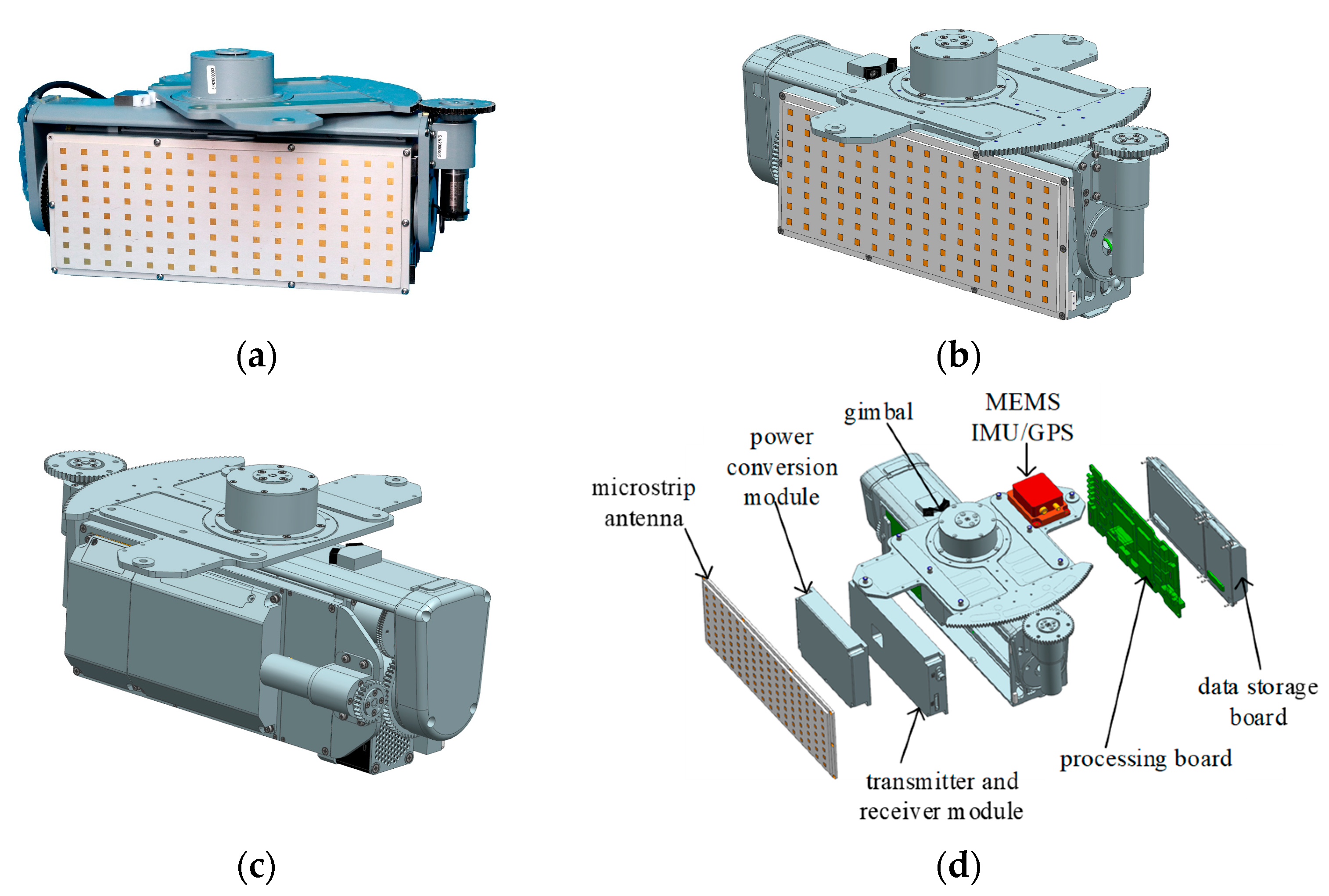
- An innovatively designed and highly integrated Ku band 4.5 kg microminiature SAR sensor is briefly introduced, which consists of a co-aperture dual-polarized patch array antenna, two-axis gimbal, 80 W solid state power amplifier, dual-channel radio frequency (RF) receiver including a built in limiter, on-board processing board performing real-time image formation, 2 TB data storage board to store dual-channel raw data and real-time SAR images, necessary power conversion module and a commercial off-the-shelf micro electro mechanical systems (MEMS)-based inertial measurement unit (IMU)/Global Position System (GPS) for motion measurement. Its performance specifications and several example SAR images with constant interpulse waveform parameters are shown to illustrate the proper function mode and excellent behavior of this 4.5 kg microminiature SAR sensor. Considerations to upgrade this SAR with the capability of the random agility of interpulse waveform parameters are given.
2. Influences of Agile Interpulse Waveform Parameters on SAR Image Formation
2.1. Agility of Carrier Frequency
2.2. Agility of Pulse Width and Chirp Rate Polarity
2.3. Agility of Initial Phase
2.4. Agility of PRI
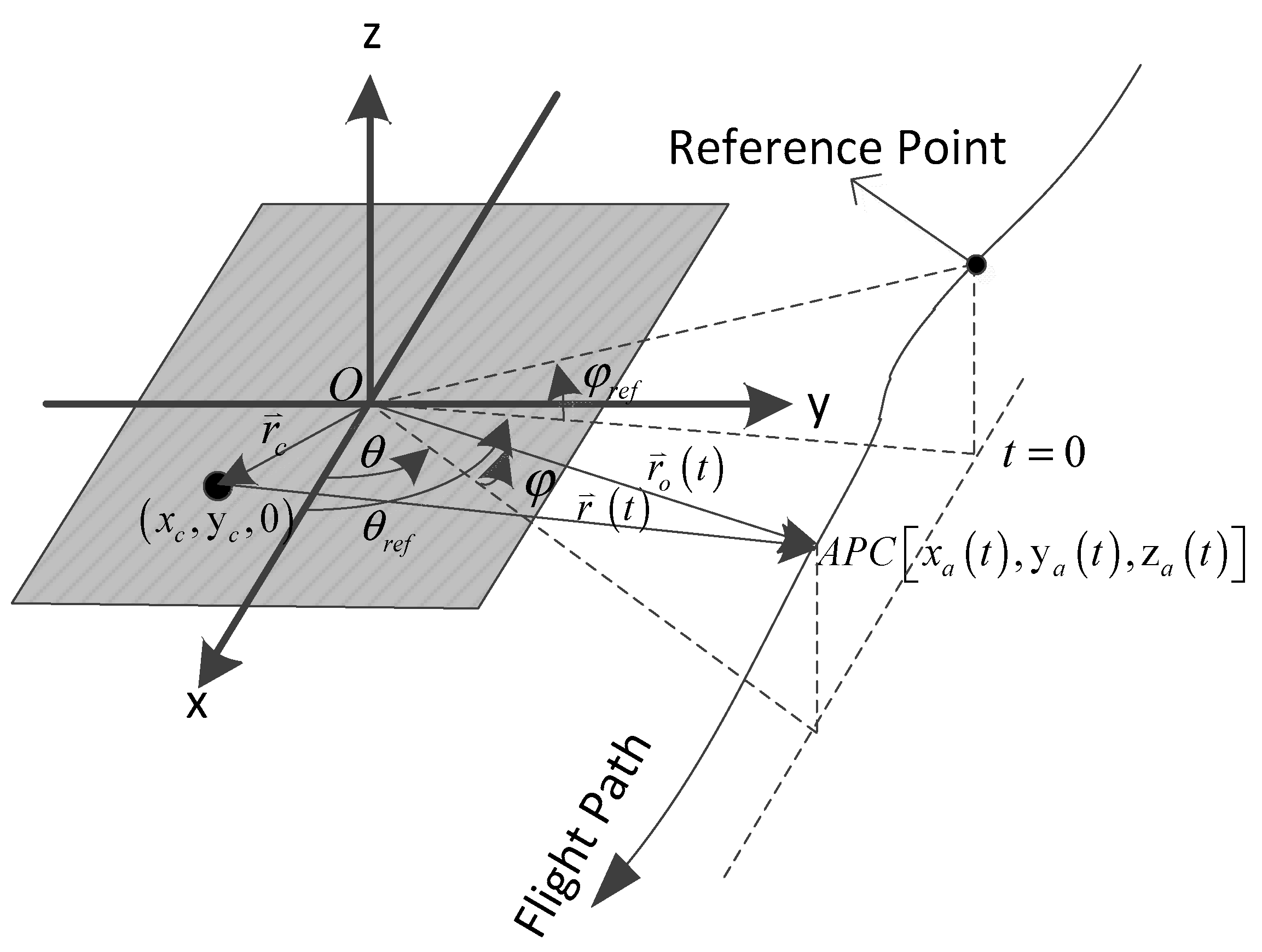
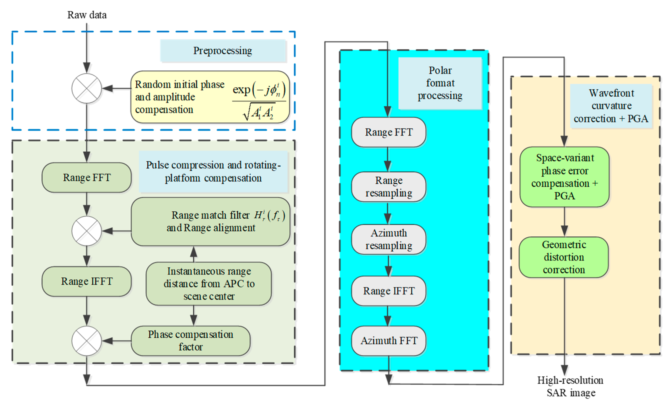
2.5. Airborne SAR Image Formation
3. Considerations on Upgrading A SAR with Agile Interpulse Waveform Parameters
3.1. Brief Introduction of 4.5 kg Microminiature SAR
3.2. Upgrading the 4.5 kg Microminiature SAR with Agile Interpulse Waveform Parameters
4. Experimental Verification of SAR Image Formation with Agile Interpulse Waveform Parameters
5. Discussion
6. Conclusions
- (1)
- The influences of agile interpulse waveform parameters on SAR imaging were analyzed. It can be seen that pulse width or chirp rate, polarity, initial phase and PRI can be randomly altered within a certain range and also can be easily compensated during the SAR imaging process. But, changing carrier frequency randomly is not recommended due to its compensation requiring a heavy computation load. From the above analysis, an efficient processing flowchart of high-resolution SAR image formation which was appropriate for agile interpulse waveform parameters was proposed. Its computation load was comparable to that of traditional SAR image formation with constant waveform parameters.
- (2)
- A Ku band 4.5 kg microminiature SAR, which was innovatively designed and highly integrated, was introduced briefly. Several example SAR images with constant interpulse waveform parameters were shown. Considerations to upgrade this SAR with the capability of random agility of interpulse waveform parameters were given.
- (3)
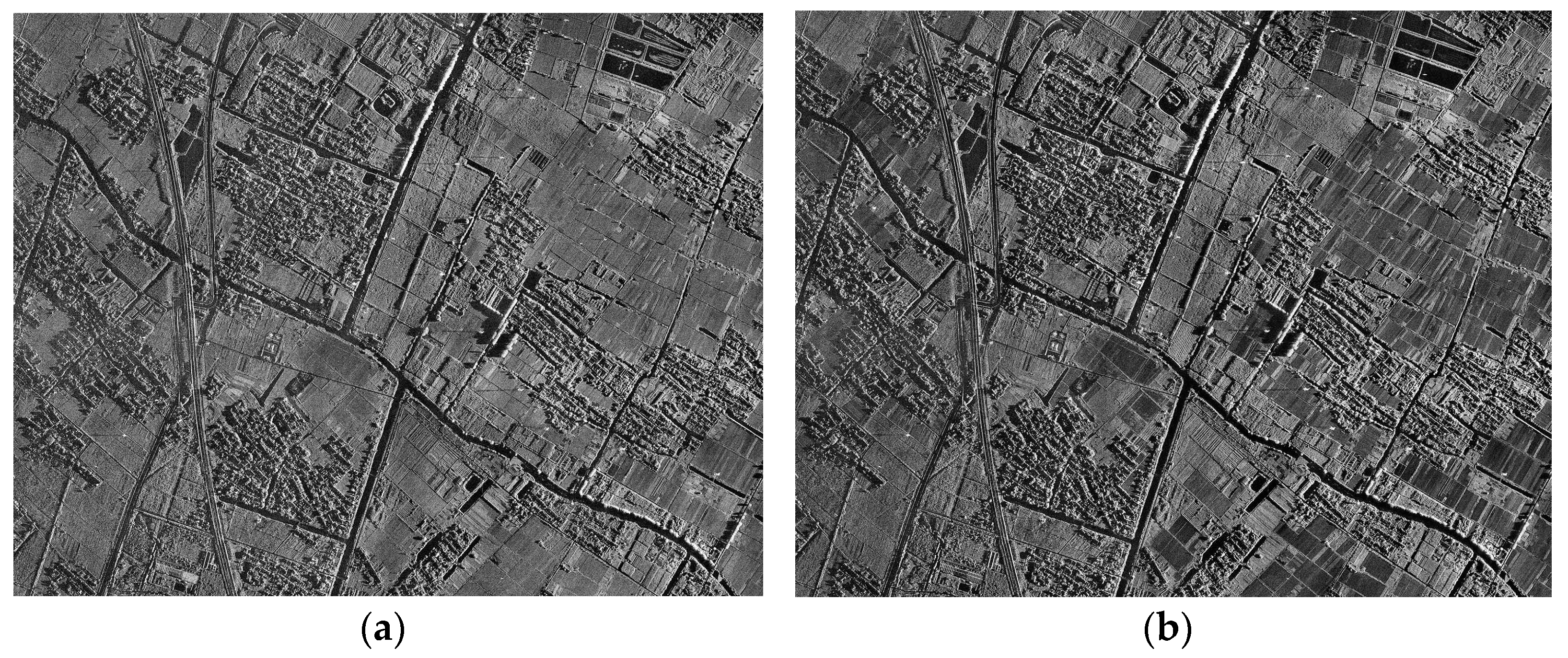
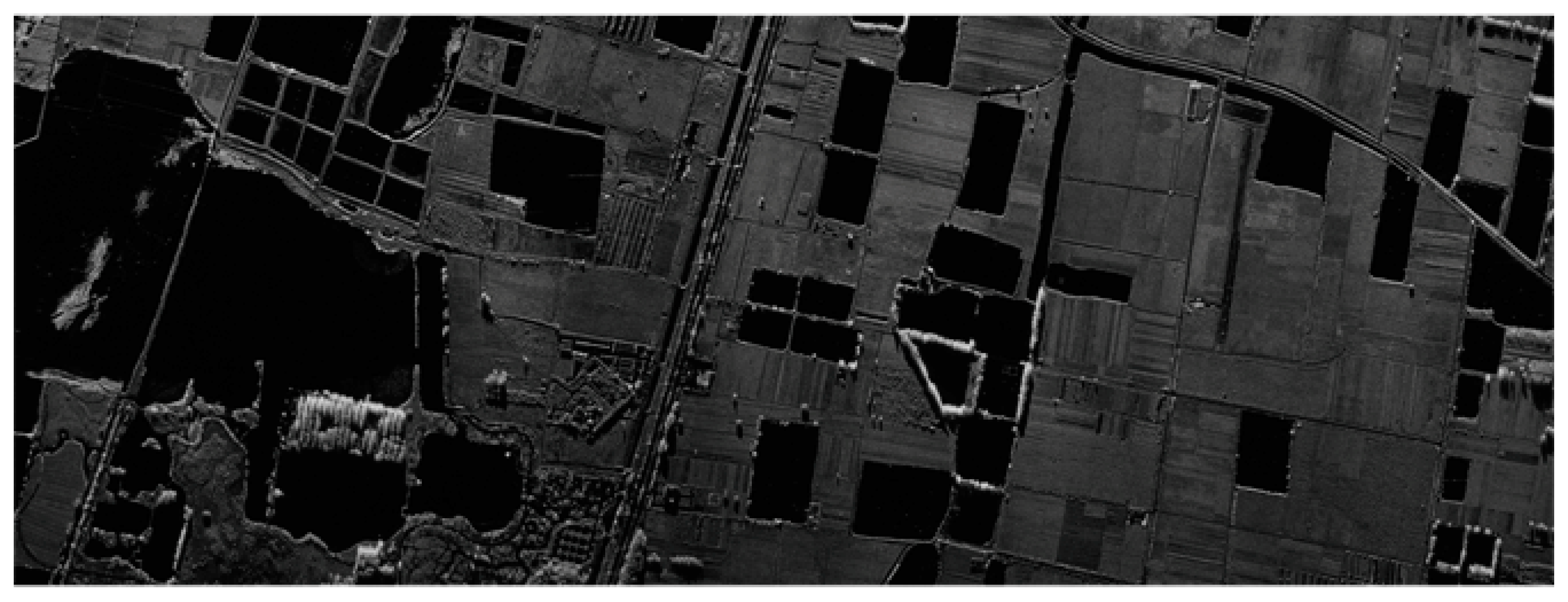
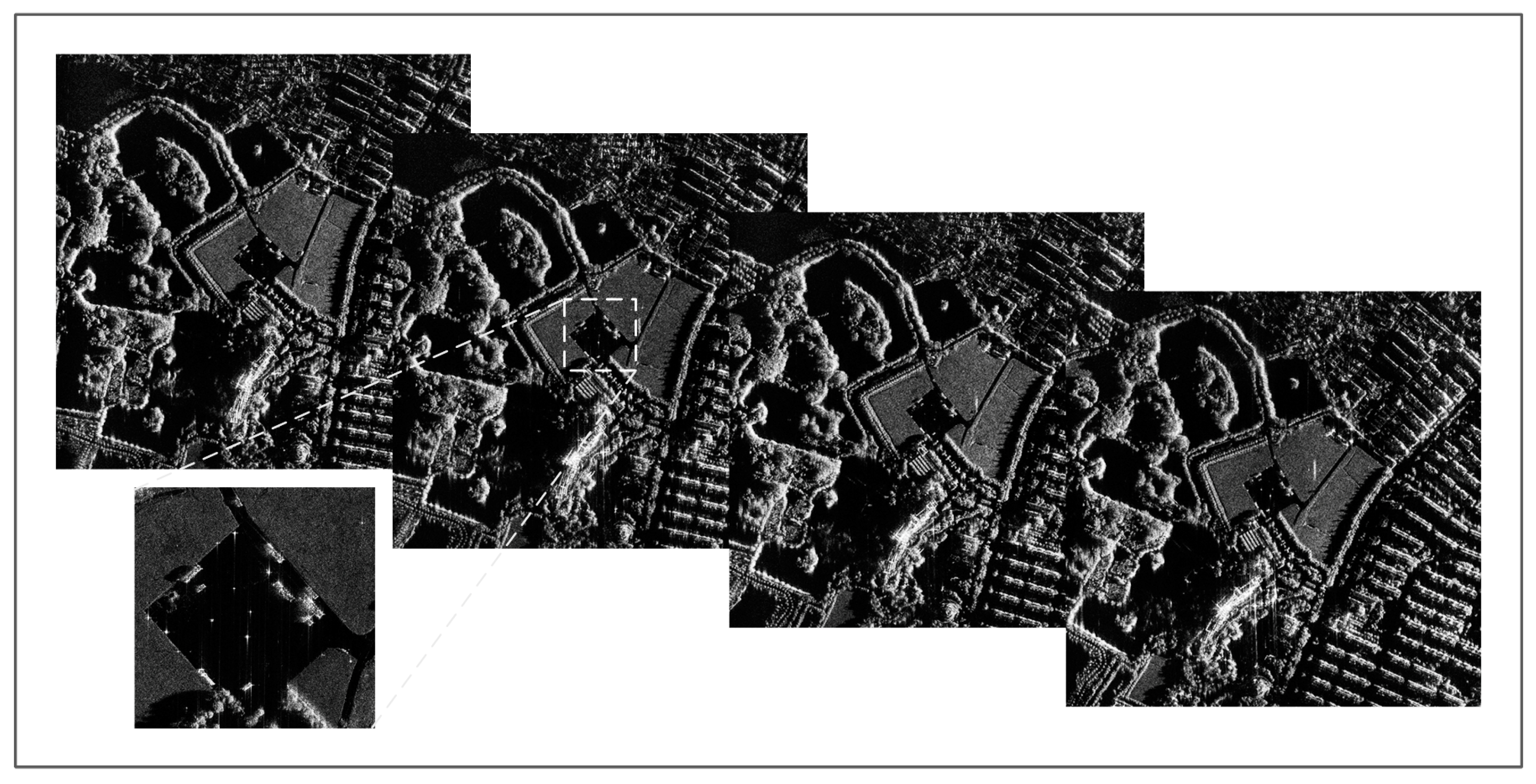
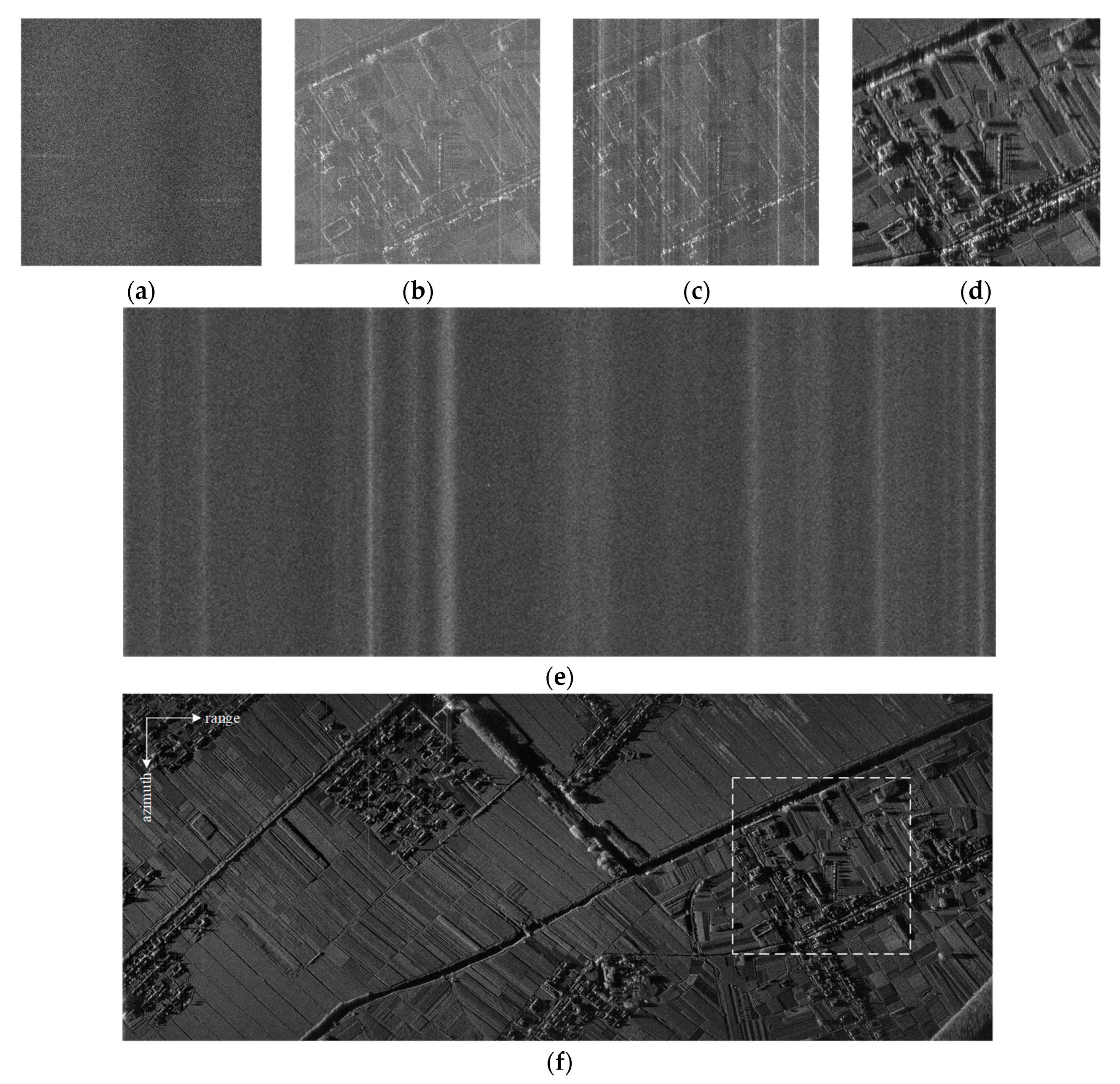
- SAR raw data with agile interpulse waveform parameters were acquired using this upgraded SAR sensor. Then, real high-resolution SAR images with resolutions of 0.5 m and 0.15 m were processed successfully from the acquired SAR raw data and were shown under the circumstance of randomly changing the transmitted wideband LFM signal waveform pulse parameters one by one.
Author Contributions
Funding
Data Availability Statement
Conflicts of Interest
References
- Goj, W.W. Synthetic Aperture Radar and Electronic Warfare; Artech House: Norwood, MA, USA, 1993. [Google Scholar]
- Schroer, R. Electronic warfare. IEEE Aerosp. Electron. Syst. Mag. 2003, 18, 49–54. [Google Scholar]
- Li, N.J.; Zhang, Y.T. A survey of radar ECM and ECCM. IEEE Trans. Aerosp. Electron. Syst. 1995, 31, 1110–1120. [Google Scholar]
- Roome, S. Digital radio frequency memory. Electron. Commun. Eng. J. 1990, 2, 147–153. [Google Scholar] [CrossRef]
- Liu, G.S.; Gu, H.; Zhu, X.H.; Sun, Y.B.; Sun, G.M.; Su, W.M. A contrast experiment of ECCM of random to pseudo-random binary phase coded CW radar. In Proceedings of the 1996 International Conference on Signal Processing, Beijing, China, 14–18 October 1996; pp. 1621–1624. [Google Scholar]
- Soumekh, M. SAR-ECCM using Phase-Perturbed LFM Chirp Signals and DRFM Repeat Jammer Penalization. IEEE Trans. Aerosp. Electron. Syst. 2006, 42, 191–205. [Google Scholar] [CrossRef]
- Garmatyuk, D.S.; Narayanan, R.M. ECCM Capabilities of an Ultrawideband Bandlimited Random Noise Imaging Radar. IEEE Trans. Aerosp. Electron. Syst. 2002, 38, 1243–1255. [Google Scholar] [CrossRef]
- Huang, Y.; Zhao, B.; Tao, M.L.; Chen, Z.Y.; Hong, W. Review of Synthetic Aperture Radar Interference Suppression. J. Radars 2020, 9, 86–106. (In Chinese) [Google Scholar]
- Yu, C.R.; Ma, X.L.; Zhang, Y.S.; Dong, Z.; Liang, D.N. Multichannel SAR ECCM based on Fast-time STAP and Pulse diversity. In Proceedings of the 2011 IEEE International Geoscience and Remote Sensing Symposium IGARSS, Vancouver, BC, Canada, 24–29 July 2011; pp. 921–924. [Google Scholar]
- Li, W.; Liang, D.N.; Dong, Z. SAR Anti-jamming Method Based on Jittering Slope Polarity of LFM and Thresholding. J. Remote Sens. 2007, 11, 171–176. (In Chinese) [Google Scholar]
- Feng, Q.Q.; Xu, H.P.; Wu, Z.F.; Sun, B. Deceptive jamming suppression for SAR on time-varying initial phase. In Proceedings of the 2016 IEEE International Geoscience and Remote Sensing Symposium IGARSS, Beijing, China, 10–15 July 2016; pp. 4996–4999. [Google Scholar]
- Zhang, Y.; Guan, Z.Q.; Li, W.Y. SAR ECCM and Imaging Based on Non-uniform PRI. In Proceedings of the 2016 International Conference on Wireless Communications WCNM, Chennai, India, 23–25 March 2016; pp. 2292–2294. [Google Scholar]
- Cui, G.L.; Fan, T.; Kong, Y.K.; Yu, X.X.; Sha, M.H.; Kong, L.J. Pseudo-random Agility Technology for Interpulse Waveform Parameters in Airborne Radar. J. Radars 2022, 11, 213–226. (In Chinese) [Google Scholar]
- Jenq, Y.C. Perfect Reconstruction of Digital Spectrum from Nonuniformly Sampled Signals. IEEE Trans. Instrum. Meas. 1997, 46, 649–652. [Google Scholar] [CrossRef]
- Zhu, D.Y.; Mao, X.H.; Li, Y.; Zhu, Z.D. Far-Field Limit of PFA for SAR Moving Target Imaging. IEEE Trans. Aerosp. Electron. Syst. 2010, 46, 917–929. [Google Scholar] [CrossRef]
- Mao, X.H.; Zhu, D.Y.; Zhu, Z.D. Polar format algorithm wavefront curvature compensation under arbitrary radar flight path. IEEE Geosci. Remote Sens. Lett. 2012, 9, 526–530. [Google Scholar] [CrossRef]
- Doerry, A.W. Performance Limits for Synthetic Aperture Radar; Sandia National Laboratories: Albuquerque, NM, USA, 2006. [Google Scholar]
- Cumming, I.G.; Wong, F.H. Digital Processing of Synthetic Aperture Radar Data: Algorithms and Implementation; Artech House: Norwood, MA, USA, 2004. [Google Scholar]
- Franceschetti, G.; Lanari, R. Synthetic Aperture Radar Processing; CRC Press: Carabas, FL, USA, 1999. [Google Scholar]
- Carrara, W.G.; Goodman, R.S.; Majewski, R.M. Spotlight Synthetic Aperture Radar Signal Processing Algorithms; Artech House: Norwood, MA, USA, 1995. [Google Scholar]
- Raney, R.K.; Runge, H.; Bamler, R.; Cumming, I.G.; Wong, F.H. Precision SAR Processing Using Chirp Scaling. IEEE Trans. Geosci. Remote Sens. 1994, 32, 786–799. [Google Scholar] [CrossRef]
- Soumekh, M. Synthetic Aperture Radar Signal Processing with MATLAB Algorithms; Wiley-Interscience: Hoboken, NJ, USA, 1999. [Google Scholar]
- Jakowatz, C.V.; Wahl, D.E.; Eichel, P.H.; Ghiglia, D.C.; Thompson, P.A. Spotlight-Mode Synthetic Aperture Radar: A Signal Processing Approach; Kluwer Academic Publishers: Norwell, MA, USA, 1996. [Google Scholar]
- Gorham, L.; Rigling, B. Scene Size Limits for Polar Format Algorithm. IEEE Trans. Aerosp. Electron. Syst. 2016, 52, 73–84. [Google Scholar] [CrossRef]
- Horvath, M.S.; Gorham, L.A.; Rigling, B.D. Scene Size Bounds for PFA Imaging with Postfiltering. IEEE Trans. Aerosp. Electron. Syst. 2013, 49, 1402–1406. [Google Scholar] [CrossRef]
- Gorham, L.A.; Rigling, B.D. Fast Corrections for Polar Format Algorithm With a Curved Flight Path. IEEE Trans. Aerosp. Electron. Syst. 2016, 52, 2815–2824. [Google Scholar] [CrossRef]
- Garber, W.L.; Hawley, R.W. Extensions to Polar Formatting with Spatially Variant Post-Filtering. In Proceedings of the 2011 Conference on Algorithms for Synthetic Aperture Radar Imagery XVIII SPIE, Orlando, FL, USA, 12–17 February 2011; pp. 1–12. [Google Scholar]
- Doren, N.E.; Jakowatz, C.V.; Wahl, D.E.; Thompson, P.A. General formulation for wavefront curvature correction in polar formatted spotlight-mode SAR images using space-variant post-filtering. In Proceedings of the 1997 International Conference on Image Processing, Santa Barbara, CA, USA, 26–29 October 1997; pp. 861–864. [Google Scholar]
- Mao, X.H.; Zhu, D.Y.; Zhang, Y.D. Knowledge-Aided Two-Dimensional Autofocus for Synthetic Aperture Radar. In Proceedings of the 2013 IEEE Radar Conference, Ottawa, ON, Canada, 29 April–3 May 2013; pp. 1–6. [Google Scholar]
- Mao, X.H.; Zhu, D.Y.; Zhu, Z.D. Autofocus correction of APE and residual RCM in Spotlight SAR polar format imagery. IEEE Trans. Aerosp. Electron. Syst. 2013, 49, 2693–2706. [Google Scholar] [CrossRef]
- Mao, X.H.; Zhu, D.Y. Two-dimensional Autofocus for Spotlight SAR Polar Format Imagery. IEEE Trans. Comput. Imag. 2016, 2, 524–539. [Google Scholar] [CrossRef]
- Zhu, D.Y.; Ye, S.H.; Zhu, Z.D. Polar Format Algorithm using Chirp Scaling for Spotlight SAR Image Formation. IEEE Trans. Aerosp. Electron. Syst. 2008, 44, 1433–1448. [Google Scholar] [CrossRef]
- Wahl, D.E.; Eichel, P.H.; Ghiglia, D.C.; Jakowatz, C.V. Phase Gradient Autofocus—A Robust Tool for High Resolution SAR Phase Correction. IEEE Trans. Aerosp. Electron. Syst. 1994, 30, 827–834. [Google Scholar] [CrossRef]

| Parameter | Value | Comments | |
|---|---|---|---|
| Weight | 4.3 kg | measured value | |
| Size (length × width × height) | 324.7 mm × 98 mm × 164.5 mm | measured value | |
| Power | +28 VDC at 125 W max | measured value | |
| Frequency Band | Ku | ||
| RF Bandwidth | 1500 MHz max | ||
| Co-aperture dual-polarized patch array Antenna | Aperture size | 250 mm × 90 mm | Measured value at center frequency. |
| Gain | 21.5 dB | ||
| Beamwidth | 8.1° AZ/19.6° EL | ||
| Sidelobe | −20.5 dB | ||
| Isolation | −35 dB | ||
| Gimbal Type | Azimuth and Elevation Dual Axis | Azimuth coverage: −90° ± 30° or +90° ± 30°, Elevation coverage: 0~180°. | |
| Transmitter/Receiver with Exciter module | Transmitter Power | 80 W peak | Solid state power amplifier |
| Noise Figure of RF Receiver | 4 dB | Includes built in limiter and dual channel receiver. | |
| RF losses | ~3 dB | Transmitter output to LNA/Limiter input. | |
| Processing/data storage module | Processing board | 1 FPGA + 2 multi-core DSP | On-board real-time image formation |
| Data storage board | 2 TB SSD | Store dual-channel raw data and real-time SAR images | |
| Power conversion module | Output all kinds of low-voltage power supply required by each module and cooling fan | The input is 28 VDC. | |
| Motion sensor | MEMS based IMU/GPS | COTS (commercial off-the-shelf) | |
| SAR Imaging modes | Spotlight and stripmap | ||
| Resolution | Spotlight | 0.15 m, 0.3 m, 0.5 m optional | |
| Stripmap | 0.3 m, 0.5 m, 1 m, 3 m optional | ||
| Maximum Range | ≮15 km | Assume 3 m resolution, −25 dB noise equivalent reflectivity | |
| Image Size | 8 K × 8 K pixels max | Both along-track and cross-track for spotlight mode | |
| SAR Imaging formation on-board | CS-PFA + SVPF + PGA | Space-Variant Post-Filtering [16,28] based Polar Format Algorithm using Chirp Scaling [32] with Phase Gradient Autofocus [33] | |
| Waveform Parameters | Value |
|---|---|
| Resolution mode/m | 0.5/0.15 |
| Bandwidth/MHz | 400/1200 |
| Chirp rate polarity | + |
| Pulse width/ | 10 |
| PRI/ | 1000 |
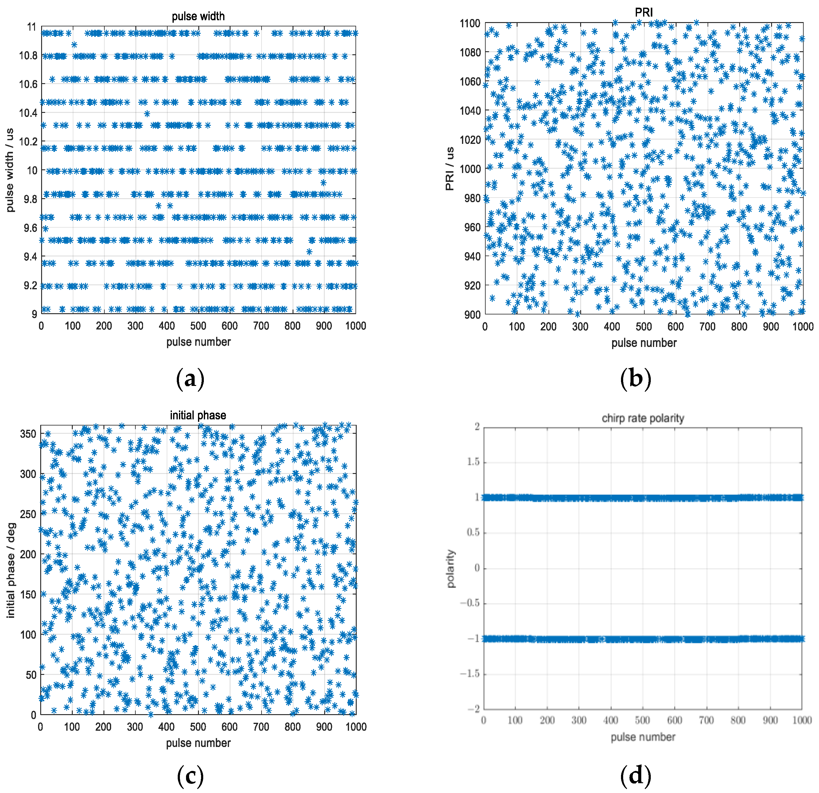
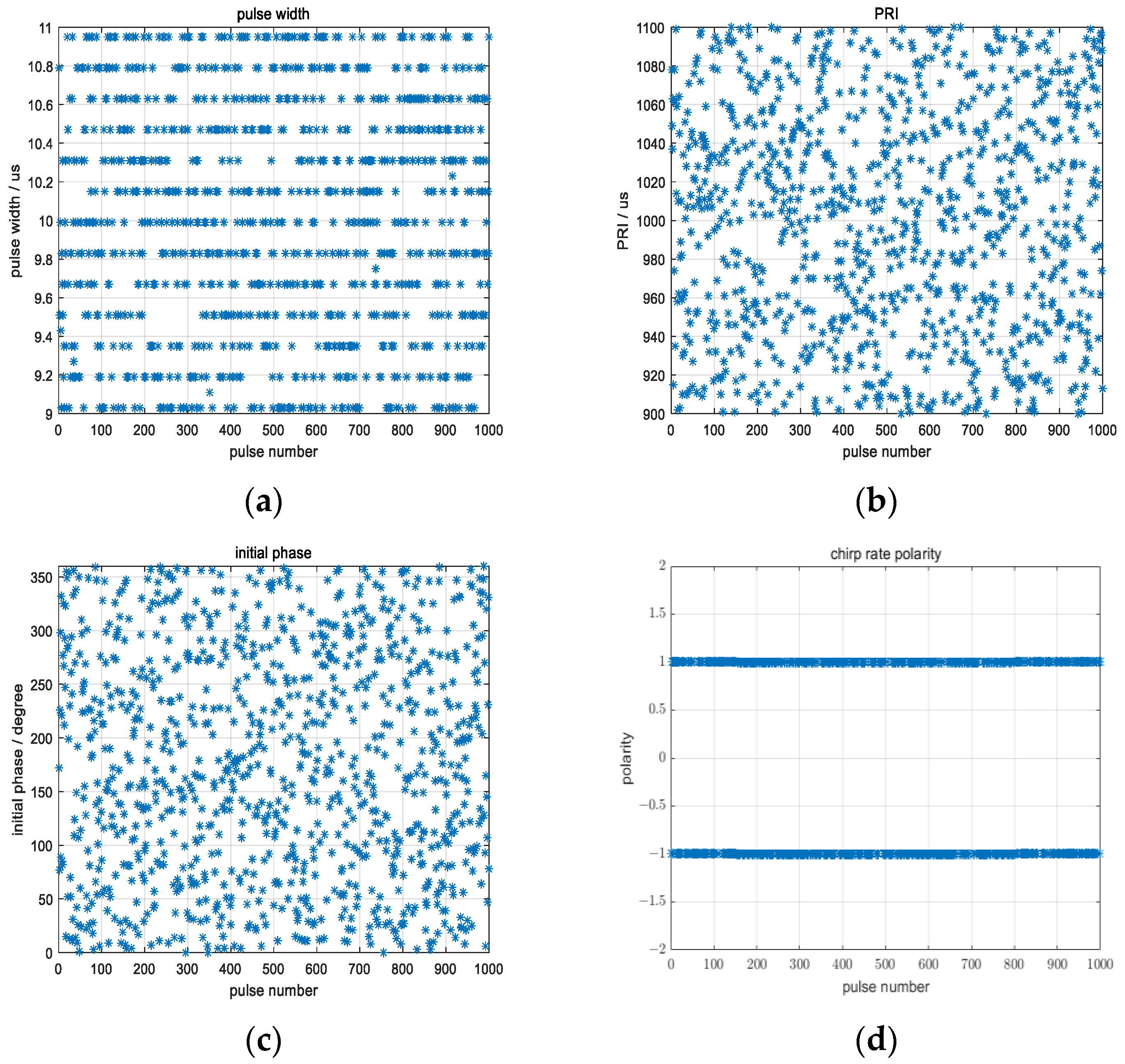
| Agile Parameters | Variation Range | Step Width |
|---|---|---|
| Pulse width/ | 9~11 | 80 ns |
| PRI/ | 900~1100 | 80 ns |
| Initial phase/° | 0~360° | 360°/214 |
| Chirp rate polarity | −1 or +1 |
Disclaimer/Publisher’s Note: The statements, opinions and data contained in all publications are solely those of the individual author(s) and contributor(s) and not of MDPI and/or the editor(s). MDPI and/or the editor(s) disclaim responsibility for any injury to people or property resulting from any ideas, methods, instructions or products referred to in the content. |
© 2023 by the authors. Licensee MDPI, Basel, Switzerland. This article is an open access article distributed under the terms and conditions of the Creative Commons Attribution (CC BY) license (https://creativecommons.org/licenses/by/4.0/).
Share and Cite
Ye, Z.; Zhu, D.; Niu, S.; Lv, J. Studies on High-Resolution Airborne Synthetic Aperture Radar Image Formation with Pseudo-Random Agility of Interpulse Waveform Parameters. Remote Sens. 2024, 16, 164. https://doi.org/10.3390/rs16010164
Ye Z, Zhu D, Niu S, Lv J. Studies on High-Resolution Airborne Synthetic Aperture Radar Image Formation with Pseudo-Random Agility of Interpulse Waveform Parameters. Remote Sensing. 2024; 16(1):164. https://doi.org/10.3390/rs16010164
Chicago/Turabian StyleYe, Zheng, Daiyin Zhu, Shilin Niu, and Jiming Lv. 2024. "Studies on High-Resolution Airborne Synthetic Aperture Radar Image Formation with Pseudo-Random Agility of Interpulse Waveform Parameters" Remote Sensing 16, no. 1: 164. https://doi.org/10.3390/rs16010164
APA StyleYe, Z., Zhu, D., Niu, S., & Lv, J. (2024). Studies on High-Resolution Airborne Synthetic Aperture Radar Image Formation with Pseudo-Random Agility of Interpulse Waveform Parameters. Remote Sensing, 16(1), 164. https://doi.org/10.3390/rs16010164