Abstract
Synthetic aperture radar (SAR) is a powerful tool for detecting and imaging targets in enclosed environments, such as tunnels and underground garages. However, SAR performance is degraded by multipath effects, which occur when electromagnetic waves are reflected by obstacles, such as walls, and interfere with the direct signal. This results in the formation of multipath ghost images, which obscure the true target and reduce the image quality. To overcome this challenge, we propose a novel method based on multi-angle observation. This method exploits the fact that the position of ghost images changes depending on the angle of the radar, while the position of the true target remains stable. By collecting and processing multiple data sets from different angles, we can eliminate the ghost images and enhance the target image. In addition, we introduce a center vector distance algorithm to address the complexity and computational intensity of existing multipath suppression algorithms. This algorithm, which defines the primary direction of multi-angle vectors from stable scattering centers as the center vector, processes and synthesizes multiple data sets from multi-angle observations. It calculates the distance of pixel intensity sequences in the composite data image from the center vector. Pixels within a specified threshold are used for imaging, and the final result is obtained. Simulation experiments and real SAR data from underground garages confirm the effectiveness of this method in suppressing multipath ghost images.
1. Introduction
Synthetic aperture radar (SAR), an advanced remote sensing technology, is renowned for its ability to generate high-resolution images and to operate in all weather and lighting conditions, including day and night [1,2,3]. These capabilities lead to the application of SAR in diverse fields such as earth sciences, agriculture, forestry, urban planning, environmental monitoring, and military reconnaissance [4,5].
In enclosed spaces, walls, floors, ceilings, and other surrounding objects act as sources of interference, causing multipath effects [6,7,8]. This causes ghost images to appear in the imaging results. This affects target evaluation and reduces the performance and effectiveness of radar detection systems [9,10]. For instance, errors in vehicle-mounted radar can lead to incorrect target localization, increasing the risk of vehicle accidents. Given these implications, the development of effective techniques for mitigating multipath effects in enclosed spaces is crucial and has garnered considerable research interest [11,12].
In radar target detection systems, there are three primary methods for suppressing multipath signals: neural network methods, compressed sensing methods, and traditional signal processing methods. Neural network methods, renowned for their adaptability, processing capability, and robustness, have been widely used in various industries. Their application in SAR target detection and ghost image suppression has been thoroughly investigated, with research mainly focusing on training networks to distinguish targets from clutter, suppress clutter, and extract targets [13,14,15,16,17,18,19]. However, these methods demand significant data and parameter input and are characterized by high computational complexity. Compressed sensing methods are revolutionizing image reconstruction by overcoming the limitations of the traditional Nyquist sampling theorem [20,21,22]. In certain applications, these methods not only reduce hardware complexity and cost but also increase resolution. For example, they enable super-resolution imaging in sparse scenes and can be integrated with other data processing techniques to augment overall system performance. However, their effectiveness depends on a certain degree of sparsity in the data, which limits their universal applicability.
Traditional signal processing methods to multipath suppression include techniques such as sub-aperture fusion, weighting function, singular value decomposition (SVD), and factor analysis (FA). The sub-aperture fusion method synthesizes coherent information from multiple sub-aperture images and achieves higher resolution than single subaperture imaging [23,24]. The method in [23] first correlates ghost images with target location, sub-aperture position, and size, then employs a double-layer fusion approach to suppress multipath ghost images, combining sub-apertures with full apertures and among themselves, followed by multiplicative and additive fusion. Although this approach diminishes ghost image intensity and improves target representation, it requires careful consideration of sub-aperture size and fusion proportion, which currently have no standardized guidelines. The weighting function method adjusts weights based on target and scene characteristics to suppress multipath signals [25,26]. While adaptive, it requires significant effort to fine-tune the parameters of the weighting function. SVD reduces data dimensions by extracting principal signal components [27,28,29], but its performance can be suboptimal with irregular data distributions. Lastly, factor analysis effectively extracts latent factors, revealing the intrinsic structure and patterns of the data [30,31,32,33]. However, this method relies on assumptions about data independence and distribution, and inaccurate assumptions can lead to uninterpretable or overlapping factors.
This paper introduces a multi-angle radar observation method to suppress multipath effects in radar detection systems. The radar acquires echo data from diverse angles by uniformly traversing its orbit. This data is then analyzed and synthesized using a center vector distance algorithm characterized by simplicity and computational efficiency. The effectiveness of this method in reducing multipath ghost images is validated through simulation experiments and real data processing in an underground garage environment.
The structure of the paper is organized as follows: Section 2 details the multi-angle observation model; Section 3 gives the multipath signal model and analyses multipath ghost images; Section 4 presents the center vector distance algorithm; Section 5 provides validation of the method using simulation experiments and real data; and Section 6 offers conclusion.
2. Multi-Angle Observation Model
Figure 1 shows the multi-angle observation method used by a radar system as it moves an orbit. On the left side of the figure, a small blue antenna (radar) is shown at various points along the orbit, each point providing a unique observation angle towards the target. This arrangement allows the radar to gather echo data from the same target at different angles. The middle part of the figure illustrates the radar moving uniformly to the right along the orbit within an environment bounded by walls. In this scenario, electromagnetic waves undergo refraction, generating multipath effects between the targets and the walls and between the targets. The radar collects echo data representing multiple angles as it covers the entire orbit. The right section of the figure demonstrates the selective extraction of specific angles from the overall data. It illustrates this selection by showing three angles: Angle1, Angle2, and Angle3. This method is also applicable to situations with more than three angles, this paper uses three angles as an example to analyze.
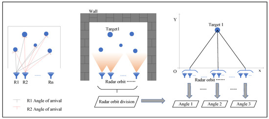
Figure 1.
Schematic diagram of multi-angle observation. Different viewing angle of radar (left). Closed space radar observation (middle). Different angle selection (right).
The geometric model of multi-angle radar observation is shown in Figure 2, where the black bold rectangle on the X-axis represents the orbit of radar movement. A right-angled coordinate system is established with the center of the orbit as the origin, extending to the right as the positive X-axis and upward as the positive Y-axis. The target location is marked by a blue circle, and the radar antenna, pointed at the target, emits frequency modulated continuous wave (FMCW) signals at regular intervals. Selected angles from the collected echo data, such as Angle1, Angle2, and Angle3, are then processed through subsequent algorithmic steps.
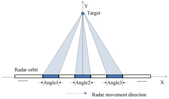
Figure 2.
Geometric model of radar multi-angle observation.
3. Multipath Signal Model
Consider the radar transmitting a frequency modulated continuous wave (FMCW) signal , where K is the frequency modulation rate, is the center frequency, and is the pulse width. The radar receives the corresponding echo signal .
In the equation, represents the complex scattering coefficient of the target, which varies across different echo paths, denoted as , t represents fast time, represents slow time. denotes the propagation path of the electromagnetic wave. Considering the signal attenuation during the electromagnetic wave propagation, this paper focuses on the path up to the third-order, . Within these paths, is the direct path, meaning the electromagnetic wave’s route to the target. and are the first and second-order multipath routes, respectively, representing the paths of the electromagnetic waves after one or two reflections. The direct path is the primary route for electromagnetic wave propagation, while the first and second-order multipaths are the main causes of multipath effects.
3.1. Target and Walls Interaction
Millimeter wave radar emits electromagnetic waves in the high-frequency spectrum, exhibiting propagation characteristics similar to light waves. Consequently, when investigating the origins of multipath signals, the primary consideration is that they arise from specular reflection [34]. The signal model shown in Figure 3 the radar R traversing a rectangular orbit, marked in orange. The walls, labeled Wall 1, Wall 2, and Wall 3, are characterized as smooth surfaces. Point P represents the target, while P1, P2, and P3 are mirror points relative to the three walls. The lines connecting the radar R to each mirror point intersect the walls at points B1, B2, and B3, where the electromagnetic waves undergo refraction. The direct propagation paths of the electromagnetic waves are shown as purple line segments, and the multipath propagation paths are highlighted in blue.
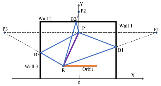
Figure 3.
Signal model for generating multipath effects between target and walls.
The coordinates of the radar position point R is (), the coordinates of the target point P is (), and the coordinates of the mirror points P1, P2, and P3 are (), (), and (), respectively. Table 1 lists the various paths: , representing the direct path; , the first-order multipath, where the first-order multipath for each of the three walls are ; and , the second-order multipath, where the corresponding second-order multipath for the three walls are .

Table 1.
Different path representations between target and walls.
Next, we illustrate the principle of locating the target and its ghost image using the specular reflection from a single wall and two radar position points, R1 and R2. This principle can be similarly applied when considering reflections from multiple walls. As shown in Figure 4, the Y-axis represents the wall within the established coordinate system. The actual orbit of the radar is represented by an orange solid line rectangle on the negative half of the X-axis, while its virtual orbit, a mirror image relative to the wall, is shown as an orange dashed line rectangle on the positive half of the X-axis. The mirror points of radar positions R1 and R2 relative to the wall are labeled and , simulating virtual radars. The target placement point P (, ) and its mirror point relative to the wall, , are also indicated.
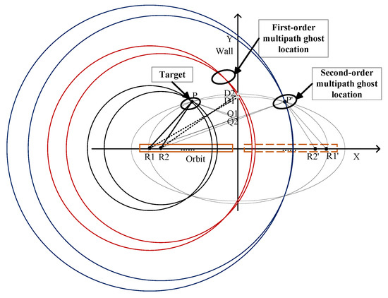
Figure 4.
Localization analysis of the multipath ghost position generated between target and wall.
In the direct path analysis, the radar conducts single-station measurements from its actual position points, creating circular constant range contours. Circles with radar position points R1 and R2 as centers and the distance to target point P as the radius are drawn. The intersection of these circles determines the target’s location, point P.
For the first-order multipath analysis, the radar and virtual radar together emulate a two-station measurement mode. Lines from radar points R1 and R2 to point intersect the Y-axis at Q1 and Q2. In this scenario, the order of electromagnetic wave propagation along the path segments does not change the result because the total path length is the same regardless of whether the wall refracts the electromagnetic wave or passes through the target first. In this two-station observation mode, elliptical equidistant contours are formed, with ellipses drawn using R1, , and R2, as focus and point as the moving point. These ellipses intersect the wall at points D1 and D2. Circles are then drawn with R1 and R2 as centers and the distances to D1 and D2 as radii, as shown by the two red circles in Figure 4. Their intersections indicate the positions of the first-order multipath ghost images.
For the second-order multipath analysis, the radar again performs single-station measurements with circular constant range contours. According to the mirror principle, |PQ1| is equal to || and |PQ2| is equal to ||. Circles are drawn with radar points R1 and R2 as centers and paths ||, || as radii. The intersections of these blue circles in Figure 4, at point , denote the position of the target’s mirror image.
In Figure 5, three observation angles, Angle1 (blue), Angle2 (red), and Angle3 (purple), are analyzed with their respective radar position points. For each angle, the analysis focuses on two points at the extreme left and right, as indicated by black dots. Figure 5a shows the direct paths for all three angles converging at the target point P. Figure 5b shows the first-order multipath ghost images for each angle, with their locations varying according to the angle of observation. The ghost image locations for Angle1, Angle2, and Angle3 are represented by blue, red, and purple points, respectively. Figure 5c shows the second-order ghost images located at the external wall’s mirror point .
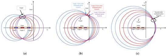
Figure 5.
Position localization analysis of target and multipath ghost under different radar viewing angles. (a) Target localization. (b) First-order multipath ghost localization. (c) Second-order multipath ghost localization.
The analysis shows that in multi-angle observation, the target point position remains constant, while the position of the first-order multipath ghost images changes with the radar observation angle. The second-order multipath ghost points are outside the wall and can be ignored. In subsequent multipath processing between the target and the wall, we mainly suppress first-order multipath ghosts.
3.2. Target and Target Interaction
Figure 6 gives the signal model for targets, P1 and P2 are two different target points. The lines connecting radar R to these targets represent their direct paths, highlighted as thick purple line segments in the figure. Additionally, a line connecting the two target points signifies the multipath propagation, depicted as a thin yellow line.
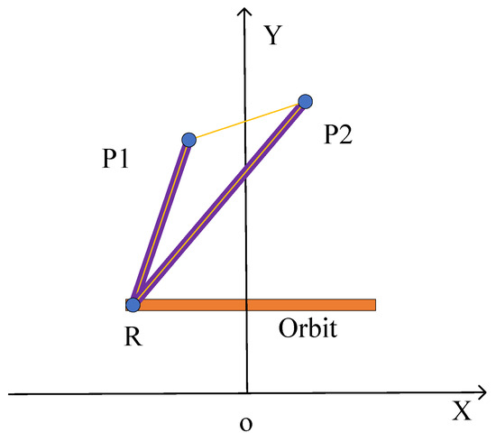
Figure 6.
Signal model for generating multipath effects between target and target.
The coordinates of the target points P1 and P2 are and , respectively. The direct paths to these targets are identified as for P1 and for P2, while the first-order multipath between them is labeled . For second-order multipath, there are two scenarios: one path extends from P1 to P2, denoted as , and the other from P2 to P1, labeled as . Detailed expressions for these paths are presented in Table 2.

Table 2.
Different path representations between target and target.
As shown in Figure 7, the target and ghost localization analysis of the interaction between two target points P1 and P2 are plotted.
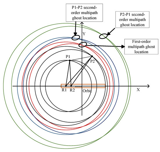
Figure 7.
Localization analysis of the multipath ghost position generated between target and target.
For the direct paths, circles are drawn centered at radar positions R1 and R2, with the radii being the distances from R1 to P1 and R2 to P1, respectively. The intersection of these circles at point P1 accurately pinpoints the target, and a similar method is applied for target point P2. These intersection points exactly define the coordinates of P1 and P2 as and .
In the first-order multipath analysis, circles are drawn with R1 as the center and half the length of the path as the radius, and similarly for R2. The locations of the first-order multipath ghost images are indicated by the intersecting points of these circles, as shown by the intersection of the two red circles in Figure 7.
For the second-order multipath, the first scenario, P1-P2, involves constructing circles with R1 as the center and half the length of as the radius, and the same approach is used for R2. The points where these circles intersect represent the second-order multipath ghost images, as indicated by the intersection of the two blue circles. The second scenario, P2-P1, follows a similar pattern, with the ghost image points being the intersections of the two green circles in Figure 7.
Figure 8a establishes the positions of two target points, P1 and P2, through direct paths. Figure 8b shows the first-order multipath ghost images for three different observation angles are determined: Angle1’s ghost image is located at the blue point, while those for Angle2 and Angle3 are indicated by red and purple points, respectively, showing that the first-order multipath ghost images vary with the observation angles. Figure 8c,d analyze the second-order multipath ghost images for two scenarios. In Figure 8c, the first scenario (P1-P2) for the three angles shows second-order ghost images as blue, red, and purple points, and the second scenario Figure 8d illustrates that these second-order ghost images also shift locations with varying radar observation angles.
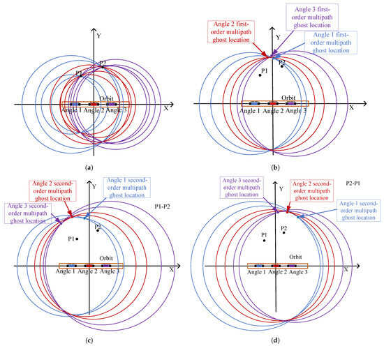
Figure 8.
Position localization analysis of target and multipath ghost under different radar viewing angles. (a) Target localization. (b) First-order multipath ghost localization. (c) P1-P2 second-order multipath ghost localization. (d) P2-P1 second-order multipath ghost localization.
From this analysis of target-to-target multipath interactions, it is clear that within multi-angle observation, the positions of the actual target points remain constant. However, both the first and second-order multipath ghost images change locations according to the radar’s observation angles. In subsequent data processing, these angle-varying ghost images are suppressed to improve the quality of the radar imaging.
4. Center Vector Distance Algorithm
This section processes the echo data from selected angles in the pixel domain. Figure 9 shows the representation of three sub-images in three-dimensional pixel space, corresponding to matrix data , , and . The workflow of the algorithm is shown in Figure 10.
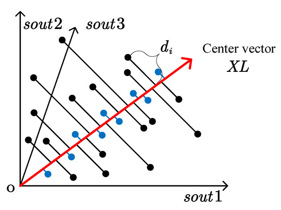
Figure 9.
Spatial pixel diagram of data observed from different angles. (Near pixels: blue; far pixels: black).
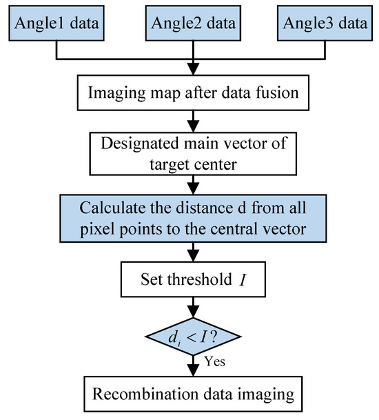
Figure 10.
Flow chart of center vector distance algorithm.
Assuming echo data from three angles are selected, denoted as , and , each data set is a matrix of size . These data corresponding to different angles are used to create three separate sub-images. Subsequently, the data from these angles are unfolded into column vectors. These vectors then constitute the three columns of a composite matrix X. The data within X is aggregated column-wise, and this aggregated data is subsequently used to generate a composite image. This composite image is constructed based on data from the three angles. This step integrates information from varied angles, culminating in a comprehensive image that more accurately captures the target’s characteristics.
Next, the center direction of the multi-angle vector of stable scattering centers is identified as the center vector XL. The algorithm then calculates the distance from the intensity sequences of all pixel points in the composite matrix X to this center vector. Figure 9 visualizes the pixel points in X, with black points representing those farther from the center vector and blue points being closer. Pixel points near the center vector, shown in blue, are retained for further analysis. The definition of the center vector is given in Equation (4). This step encapsulates the algorithm’s fundamental concept: by discarding pixel points of multipath ghost images away from the stable scattering center, it achieves the goal of multipath suppression.
The distance of each pixel point to the center vector in the composite matrix X is computed as follows: the intensity value of each row of pixels in X is first projected onto , represented as , as described in Equation (5), where . This leads to the formulation presented in Equation (6). Then, the distance between each row vector’s intensity value and the center vector is calculated, as detailed in Equation (7), resulting in the values defined in Equation (8).
Each value in is then compared to a predefined threshold value I. Based on this comparison, a logical column vector is created, which is then expanded and used to multiply X. The matrix is restructured according to the original data size of and re-imaged to produce a final result that effectively suppresses multipath ghost images. The dimensions of all datasets are shown in Figure 11, offering a clear visual overview of the data sizes and structural layout used in the algorithm. All images in this paper are generated using the Back Projection (BP) algorithm. The essence of the BP algorithm is its ability to back-project received signals or data along their original paths back into the image domain. This approach directly constructs an image of the target, avoiding the need for complex transformations and preprocessing. Its advantage lies in its simplicity and versatility, enabling adaptation to various data types and a wide range of application scenarios [35].
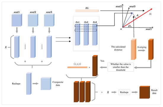
Figure 11.
Data processing structure schematic diagram of center vector distance algorithm.
5. Experimental Validation
5.1. Simulation Validation
A simulation experiment was performed using Matlab software to verify the multipath ghost suppression effect between target and walls, and between targets. The main parameters of the simulation are detailed in Table 3.

Table 3.
Main simulation parameter settings.
5.1.1. Target and Wall Interaction
The experiment includes a radar, an orbit, the target P, and three walls (right wall 1, back wall 2, left wall 3). In a spatial Cartesian coordinate system, the radar orbit is 2 m long, spanning the X-axis from to 1, with the target point P at . The right wall 1 is at , the left wall 3 is at , and the back wall 2 connects the tops of the two side walls at .
The black lines in the figures represent walls, and the target point is at . Figure 12a–c show imaging results from three angles, with first-order multipath ghost images (Wall1-1, Wall2-1, Wall3-1) and second-order ghost images (Wall1-2, Wall2-2, Wall3-2) indicated by white arrows in Figure 12a. Table 4 lists the central coordinates of the first-order multipath ghost images for the three walls at different angles, showing that their positions vary with the angle. Figure 12d is a composite image of the three angles, where the scattering distribution of the multipath ghost images shows their varying positions at different angles. Figure 12e shows the result of applying the sub-aperture fusion method. This method performs a double-layer fusion of sub-apertures. The first layer multiplies the sub-apertures and the full aperture, and the second layer groups and adds the multiplied sub-apertures. Figure 12f shows the result after suppressing ghost images using the method proposed in this paper, where the first-order multipath ghost images are suppressed, and the second-order ghost images outside the wall are ignored.


Figure 12.
Simulation results between target and walls. (a) Angle 1 image. (b) Angle 2 image. (c) Angle 3 image. (d) Three angle composite image. (e) The result of sub-aperture fusion method. (f) The results of our method.

Table 4.
First-order multipath ghost locations at different angles.
5.1.2. Target to Target Interaction
In the same coordinate system as the first experiment, this experiment involves a radar, an orbit, and two target points. Target one, P1, is located at , and target two, P2, is located at .
Figure 13a–c show imaging results from three different angles. In Figure 13a, White arrows indicate the first-order multipath ghost image P-1 between the two targets, and the second-order ghost image positions P12-2 and P21-2 from P1 to P2 and P2 to P1, respectively. Table 5 lists the specific coordinates of first and second-order multipath ghost images at different angles, demonstrating that these ghost images change with the radar observation angle. Figure 13d shows a composite image of the three angles, with a scattered distribution of multipath ghost images, indicating their varying positions at different angles. Figure 13e shows the result after applying the sub-aperture fusion method. This method can suppress multipath ghosting but the target information is also lost. Figure 13f shows the image after ghost image suppression using the method proposed in this paper, where only the two target points are visible, and both first and second-order multipath ghost images are completely suppressed, showing significant effectiveness.
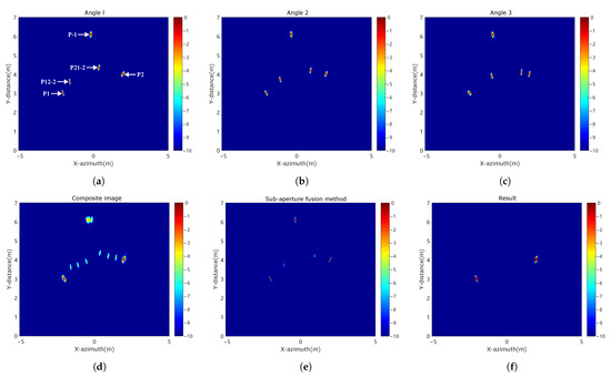
Figure 13.
Simulation results between target and target. (a) Angle 1 image. (b) Angle 2 image. (c) Angle 3 image. (d) Three angle composite image. (e) The result of sub-aperture fusion method. (f) The results of our method.

Table 5.
First-order and second-order multipath ghost locations at different angles.
This paper’s processing results are evaluated using the signal to clutter ratio (SCR). The SCR is defined as the pixel energy ratio between the target and the ghost areas, as shown in Equation (9), where represents the target area and represents the ghost area. Table 6 details the SCR values for different scenarios: different observation angles, composite images, the sub-aperture fusion method, and our method, all in the context of the two simulation experiments.

Table 6.
SCR of different methods under different experiments.
5.2. Practical Data Validation
This section presents a validation and evaluation of the performance and effectiveness of the proposed method in real scenarios using actual data collected in an underground parking garage. The data were acquired using a millimeter-wave radar system, specifically the IWR1642BOOST, and DCA1000EVM, with the help of mmWavestudio software. The main parameter settings are documented in Table 7.

Table 7.
Main parameters of radar in experiments.
5.2.1. Experiment One
As shown in Figure 14a, the experimental arrangement involved positioning two corner reflectors at 1 and 2 m from the left wall and 1 m away from the back wall. The radar and its orbit were situated 2 m from the targets and aligned parallel to the back wall. During imaging, the midpoint of the radar orbit served as the coordinate origin, with the right and forward directions as positive.
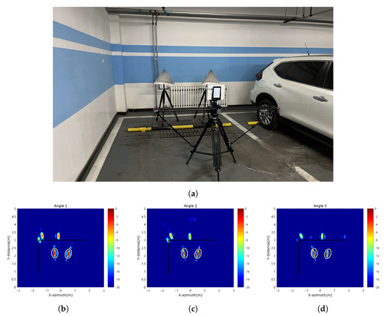

Figure 14.
Results of Experiment 1. (a) The scene image of this experiment. (b) Angle 1 image. (c) Angle 2 image. (d) Angle 3 image. (e) Three angle composite image. (f) The result of sub-aperture fusion method. (g) The results of our method.
Figure 14b–d show the imaging results from different angles, where black bold lines represent the left and back walls. Yellow ellipses highlight the two targets. The composite image Figure 14e shows that the multipath ghost distribution is more scattered, indicating that it is not at the same location at different angles. Figure 14f presents the result after applying the sub-aperture fusion method. This method can suppress ghosts but loses targets information. Figure 14g shows the suppression effect using the method proposed in this paper. The results show that the proposed method effectively suppresses multipath ghost images while retaining as much targets information as possible. The two strong scatters at the up-left corner have a stable scattering center, the scattering intensity does not change, and the position does not change with the angle, which is not our main suppress. The strong scatters is stronger than that in the sub-aperture fusion method, because the sub-aperture fusion method will multiply the pixels during processing, which will cause the strong ones to be stronger and the weak ones to be weaker. Our method does not perform multiplication but processes directly on the composite image without changing the amplitude. The overall relative intensity of the two images is unchanged and does not affect the evaluation of the results.
5.2.2. Experiment Two
In the experimental arrangement depicted in Figure 15a, a vehicle is stationed in a parking space, with the radar and its orbit placed 2 m directly in front of the vehicle. The vehicle is one parking space away from the left wall, with the rear wall located directly behind the vehicle.
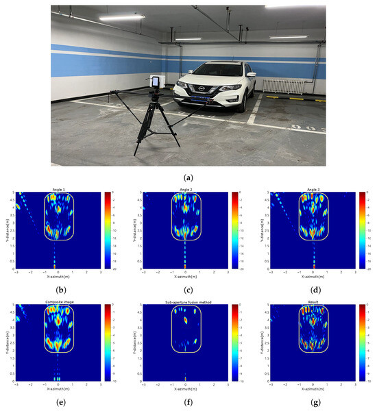
Figure 15.
Results of Experiment 2. (a) The scene image of this experiment. (b) Angle 1 image. (c) Angle 2 image. (d) Angle 3 image. (e) Three angle composite image. (f) The result of sub-aperture fusion method. (g) The results of our method.
Figure 15b–d show the echo images from different angles. Yellow borders outline the vehicle contour. The composite image in Figure 15e shows a more scattered distribution of multipath ghost images, indicating that their observed positions vary with different angles. Figure 15f shows the processing results of the sub-aperture fusion method. This method can suppress ghosts, but will lose a lot of target information, making it difficult to determine the target. Figure 15g shows the suppression effect using the method proposed in this paper, clearly showing that multipath ghosting is effectively suppressed while retaining as much target information as possible.
The signal to clutter ratio (SCR) is used to evaluate the processing effectiveness of different methods with real data. Table 8 lists the SCR for different angles, composite image, sub-aperture fusion method, and our method in the two experiments.

Table 8.
SCR of different methods under different experiments.
6. Conclusions
This paper analyzes and suppresses ghost images caused by multipath effects in enclosed spaces such as underground garages and tunnels. It introduces a multi-angle radar observation method and a center vector distance algorithm to eliminate these effects. First, the location and characteristics of multipath ghosts between target and walls and between targets are analyzed in detail. Next, it applies the center vector distance algorithm to suppress ghost images by collecting and processing echo data from different angles, exploiting the fact that multipath ghost images change with the radar observation angle. Finally, simulation experiments and real data processing were conducted. The SCR results showed that the method proposed in this paper has the highest SCR value, verifying its effectiveness in suppressing ghost images and mitigating multipath effects.
Author Contributions
Conceptualization, Y.L. (Yun Lin); methodology, Y.L. (Yun Lin) and J.Z.; software, Y.L. (Yun Lin) and J.Z.; validation, Y.L. (Yun Lin) and J.Z.; formal analysis, Y.L. (Yun Lin) and J.Z.; resources, W.S. and Y.L. (Yang Li); writing—original draft preparation, Y.L. (Yun Lin) and J.Z.; writing—review and editing, Y.L. (Yun Lin), J.Z., Y.W., Y.L. (Yang Li), W.S. and Z.B.; supervision, Y.L. (Yun Lin); project administration, Y.W.; funding acquisition, Y.L. (Yun Lin) and Y.W. All authors have read and agreed to the published version of the manuscript.
Funding
This research was funded by The National Natural Science Foundation of China, grant numbers 62131001 and 62371005; and the Innovation Team Building Support Program of the Beijing Municipal Education Commission, grant number IDHT20190501.
Data Availability Statement
Data are available on request due to restrictions of privacy.
Acknowledgments
We thank the good advice and comments from anonymous reviewers to help improve the quality of the paper.
Conflicts of Interest
The authors declare no conflict of interest.
References
- Doerry, A. Introduction to Synthetic Aperture Radar. In Proceedings of the 2019 IEEE Radar Conference (RadarConf), Boston, MA, USA, 22–26 April 2019; pp. 1–90. [Google Scholar] [CrossRef]
- Çetin, M.; Stojanović, I.; Önhon, N.O.; Varshney, K.; Samadi, S.; Karl, W.C.; Willsky, A.S. Sparsity-Driven Synthetic Aperture Radar Imaging: Reconstruction, autofocusing, moving targets, and compressed sensing. IEEE Signal Process. Mag. 2014, 31, 27–40. [Google Scholar] [CrossRef]
- Krishnan, V.; Swoboda, J.; Yarman, C.E.; Yazici, B. Multistatic Synthetic Aperture Radar Image Formation. IEEE Trans. Image Process. 2010, 19, 1290–1306. [Google Scholar] [CrossRef]
- Hosseiny, B.; Amini, J.; Aghababaei, H. Structural displacement monitoring using ground-based synthetic aperture radar. Int. J. Appl. Earth Obs. Geoinf. 2023, 116, 103144. [Google Scholar] [CrossRef]
- Ram, S.S. Fusion of Inverse Synthetic Aperture Radar and Camera Images for Automotive Target Tracking. IEEE J. Sel. Top. Signal Process. 2023, 17, 431–444. [Google Scholar] [CrossRef]
- Leigsnering, M.; Amin, M.; Ahmad, F.; Zoubir, A.M. Multipath Exploitation and Suppression for SAR Imaging of Building Interiors: An overview of recent advances. IEEE Signal Process. Mag. 2014, 31, 110–119. [Google Scholar] [CrossRef]
- Xiao, P.; Tian, X.; Liu, M.; Liu, W. Multipath Smearing Suppression for Synthetic Aperture Radar Images of Harbor Scenes. IEEE Access 2019, 7, 20150–20162. [Google Scholar] [CrossRef]
- Tan, Q.; Leung, H.; Song, Y.; Wang, T. Multipath ghost suppression for through-the-wall radar. IEEE Trans. Aerosp. Electron. Syst. 2014, 50, 2284–2292. [Google Scholar] [CrossRef]
- Martinez-Lorenzo, J.A.; Rappaport, C.M.; Quivira, F. Physical Limitations on Detecting Tunnels Using Underground-Focusing Spotlight Synthetic Aperture Radar. IEEE Trans. Geosci. Remote Sens. 2011, 49, 65–70. [Google Scholar] [CrossRef]
- Kim, Y.D.; Son, G.J.; Kim, J.; Jung, W. Performance Comparision of Vehicular Radar System between On-Road and Tunnel Space. In Proceedings of the 2016 5th IIAI International Congress on Advanced Applied Informatics (IIAI-AAI), Kumamoto, Japan, 10–14 July 2016; pp. 1209–1210. [Google Scholar] [CrossRef]
- Lee, J.E.; Lim, H.S.; Jeong, S.H.; Kim, S.C.; Choi, Y.S.; Shin, H.C. Enhanced iron-tunnel recognition for automotive radars. In Proceedings of the 2015 16th International Radar Symposium (IRS), Dresden, Germany, 24–26 June 2015; pp. 149–154. [Google Scholar] [CrossRef]
- Kim, Y.D.; Son, G.J.; Song, C.H.; Kim, H.K. On the Deployment and Noise Filtering of Vehicular Radar Application for Detection Enhancement in Roads and Tunnels. Sensors 2018, 18, 837. [Google Scholar] [CrossRef] [PubMed]
- Pei, J.; Huang, Y.; Huo, W.; Zhang, Y.; Yang, J.; Yeo, T.S. SAR Automatic Target Recognition Based on Multiview Deep Learning Framework. IEEE Trans. Geosci. Remote Sens. 2018, 56, 2196–2210. [Google Scholar] [CrossRef]
- Park, J.K.; Park, J.H.; Kim, K.T. Multipath Signal Mitigation for Indoor Localization Based on MIMO FMCW Radar System. IEEE Internet Things J. 2023, 11, 2618–2629. [Google Scholar] [CrossRef]
- Zheng, Z.; Zhang, Y.; Peng, X.; Xie, H.; Chen, J.; Mo, J.; Sui, Y. MIMO Radar Waveform Design for Multipath Exploitation Using Deep Learning. Remote Sens. 2023, 15, 2747. [Google Scholar] [CrossRef]
- Qu, L.; Wang, C.; Yang, T.; Zhang, L.; Sun, Y. Enhanced Through-the-Wall Radar Imaging Based on Deep Layer Aggregation. IEEE Geosci. Remote Sens. Lett. 2022, 19, 1–5. [Google Scholar] [CrossRef]
- Wang, X. Electronic radar signal recognition based on wavelet transform and convolution neural network. Alex. Eng. J. 2022, 61, 3559–3569. [Google Scholar] [CrossRef]
- Zhang, F.; Meng, T.; Xiang, D.; Ma, F.; Sun, X.; Zhou, Y. Adversarial Deception Against SAR Target Recognition Network. IEEE J. Sel. Top. Appl. Earth Obs. Remote Sens. 2022, 15, 4507–4520. [Google Scholar] [CrossRef]
- Zhang, X.; Feng, S.; Zhao, C.; Sun, Z.; Zhang, S.; Ji, K. MGSFA-Net: Multi-Scale Global Scattering Feature Association Network for SAR Ship Target Recognition. IEEE J. Sel. Top. Appl. Earth Obs. Remote Sens. 2024; 1–15, Epub ahead of printing. [Google Scholar] [CrossRef]
- Liu, J.; Tian, X.; Jiang, J.; Huang, K. Distributed Compressed Sensing Based Ground Moving Target Indication for Dual-Channel SAR System. Sensors 2018, 18, 2377. [Google Scholar] [CrossRef]
- Zhang, L.; Xing, M.; Qiu, C.W.; Li, J.; Sheng, J.; Li, Y.; Bao, Z. Resolution Enhancement for Inversed Synthetic Aperture Radar Imaging Under Low SNR via Improved Compressive Sensing. IEEE Trans. Geosci. Remote Sens. 2010, 48, 3824–3838. [Google Scholar] [CrossRef]
- Tang, J.; Liu, Z.; Ran, L.; Xie, R.; Qin, J. Enhancing Forward-Looking Image Resolution: Combining Low-Rank and Sparsity Priors. IEEE Trans. Geosci. Remote Sens. 2023, 61, 1–12. [Google Scholar] [CrossRef]
- Shen, W.; Jin, L.; Liu, Q. Through-the-Wall Radar Indoor Multipath Mechanism Analysis and Mitigation Strategies. Radar Sci. Technol. 2016, 14, 605–613. [Google Scholar]
- Li, J.; Chen, D.; Chen, J.; Zhu, Y. Multipath Virtual Image Suppression of Through-the-Wall Imaging Radar Under Strong Clutter Background. Radar Sci. Technol. 2020, 155, 145–150. [Google Scholar]
- Zhou, H.; He, Y.; Wang, Y.; Duan, R. Virtual multi-views method for through-wall radar imaging based on Green function. In Proceedings of the IET International Radar Conference, Hangzhou, China, 14–16 October 2015; pp. 1–5. [Google Scholar] [CrossRef]
- Zhou, Y.; Huang, C.; Liu, H.; Li, D.; Truong, T.K. Front-Wall Clutter Removal in Through-the-Wall Radar Based on Weighted Nuclear Norm Minimization. IEEE Geosci. Remote Sens. Lett. 2022, 19, 1–5. [Google Scholar] [CrossRef]
- Gao, Y.F.; Gui, G.; Cong, X.; Yang, Y.; Zou, Y.; Wan, Q. Multi-linear sparse reconstruction for SAR imaging based on higher-order SVD. EURASIP J. Adv. Signal Process. 2017, 2017, 44. [Google Scholar] [CrossRef]
- Zhang, S.; Zhu, Y.; Dong, G.; Kuang, G. Truncated SVD-Based Compressive Sensing for Downward-Looking Three-Dimensional SAR Imaging With Uniform/Nonuniform Linear Array. IEEE Geosci. Remote Sens. Lett. 2015, 12, 1853–1857. [Google Scholar] [CrossRef]
- Liu, S.; Qi, Q.; Cheng, H.; Sun, L.; Zhao, Y.; Chai, J. A Vital Signs Fast Detection and Extraction Method of UWB Impulse Radar Based on SVD. Sensors 2022, 22, 1177. [Google Scholar] [CrossRef]
- Zhang, Z.; Zhang, B.; Jiang, C.; Xiang, Y.; Hong, W.; Wu, Y. Influence factors of sparse microwave imaging radar system performance: Approaches to waveform design and platform motion analysis. Sci. China Inf. Sci. 2012, 55, 2301–2317. [Google Scholar] [CrossRef][Green Version]
- Xu, Q.; Jin, T.; Qiu, L. “Ghost” suppression for through-the-wall radar with MIMO antenna arrays based on multi-feature combination. Mod. Electron. Tech. 2015, 38, 7. [Google Scholar]
- Woo, S.H.; Shin, J.J.; Kim, J. Implementation and Analysis of Pattern Propagation Factor Based Radar Model for Path Planning. J. Intell. Robot. Syst. 2019, 96, 517–528. [Google Scholar] [CrossRef]
- Qu, L.; Yang, Y.; Yang, T. MIMO Through-the-Wall Radar Imaging Based on 2D Minimum Phase Coherence Factor. Telecommun. Eng. 2021, 61, 1534–1539. [Google Scholar]
- Setlur, P.; Smith, G.E.; Ahmad, F.; Amin, M.G. Target Localization with a Single Sensor via Multipath Exploitation. IEEE Trans. Aerosp. Electron. Syst. 2012, 48, 1996–2014. [Google Scholar] [CrossRef]
- Zhang, B.; Xu, G.; Zhou, R.; Zhang, H.; Hong, W. Multi-Channel Back-Projection Algorithm for mmWave Automotive MIMO SAR Imaging With Doppler-Division Multiplexing. IEEE J. Sel. Top. Signal Process. 2023, 17, 445–457. [Google Scholar] [CrossRef]
Disclaimer/Publisher’s Note: The statements, opinions and data contained in all publications are solely those of the individual author(s) and contributor(s) and not of MDPI and/or the editor(s). MDPI and/or the editor(s) disclaim responsibility for any injury to people or property resulting from any ideas, methods, instructions or products referred to in the content. |
© 2024 by the authors. Licensee MDPI, Basel, Switzerland. This article is an open access article distributed under the terms and conditions of the Creative Commons Attribution (CC BY) license (https://creativecommons.org/licenses/by/4.0/).