Abstract
The Ice, Cloud, and Land Elevation Satellite-2 (ICESat-2), launched in September 2018, has been widely used in forestry and surveying. A high-accuracy digital elevation model (DEM)/digital surface model (DSM) for terrain matching can effectively evaluate the ICESat-2 design requirements and provide essential data support for further study. The conventional terrain-matching methods regard the laser ground track as a whole, ignoring the individual differences caused by the interaction of photons during flight. Therefore, a novel terrain-matching method using a two-dimensional affine transformation model was proposed to describe the deformation of laser tracks. The least-square optimizes the model parameters with the high-accuracy terrain data to obtain the best matching result. The results in McMurdo Dry Valley (MDV), Antarctica, and Zhengzhou (ZZ), China, demonstrate that the proposed method can verify geolocation accuracy and indicate that the average horizontal accuracy of ICESat-2 V5 data is about 3.86 m in MDV and 4.67 m in ZZ. It shows that ICESat-2 has good positioning accuracy, even in mountainous areas with complex terrain. Additionally, the random forest (RF) model was calculated to analyze the influence of four factors on geographic location accuracy. The slope and signal-to-noise ratio (SNR) are considered the crucial factors affecting the accuracy of ICESat-2 data.
1. Introduction
The Geoscience Laser Altimeter System (GLAS) on NASA’s Ice, Cloud, and Land Elevation Satellite (ICESat) is the first satellite-based laser altimetry in the world, and has provided high-accuracy data on a global scale [1,2]. However, in 2009, ICESat stopped working because of the failure of its laser sensor. Fortunately, the Ice, Cloud, and Land Elevation Satellite-2 (ICESat-2), equipped with an advanced topographic laser altimeter system (ATLAS), was launched from California in 2018. As the successor of ICESat, the primary goal of ICESat-2 is to monitor the changes in sea ice freeboard at centimeter accuracy [3]. Additionally, it provides repeated altimetry measurements for land, vegetation, ocean, and inland water [4].
Accurate calibration and verification of measurements are crucial for all satellite missions, especially those involving novel instruments or technologies such as the photon-counting laser altimeter on ICESat-2. Over the past few years, the positioning accuracy of ICESat-2 products has been verified under different conditions. Wang et al. [5] compared the ground elevations retrieved from the ICESat-2 data and the airborne LiDAR-derived ground elevation. The calculated mean difference and root mean square error (RMSE) of the ICESat-2 product are −0.61 m and 1.96 m, respectively. However, only the vertical accuracy of ICESat-2 data is verified, while the horizontal accuracy is ignored. The alignment errors and time-varying pointing biases of the on-orbit laser will significantly affect the horizontal positioning accuracy [6]. The stringent laser surface bounce point horizontal (on the surface) geolocation knowledge requirement is 6.5 m, and the best estimate before launch is 4.9 m [7].
When the ground is uneven, the deviation of horizontal photon coordinates can lead to an additional elevation error, as shown in equation , where is the horizontal positioning error of the photon, is the slope angle and is the quadratic elevation error of the photon. Assuming that the terrain slope is 30°, the horizontal positioning accuracy is 6.5 m (as required), which could lead to a potential elevation error of 5.94 cm. In mountainous areas, the elevation error caused by the quadratic effect may become larger with the increase in slope. For a massive area of ice, a small change in surface height can considerably impact sea level estimation. For the area above 2000 m in Greenland, ice sheet change rates correspond to a volume change rate of [8]. It is necessary to evaluate the horizontal positioning accuracy of ICESat-2. However, it is a great challenge to verify the horizontal accuracy of ICESat-2. Firstly, the slice data obtained by ICESat-2 lacks an appropriate accuracy index. Secondly, the proposed accuracy verification methods regard the laser track as a whole, without considering the individual differences of photons.
At present, the verification methods for the horizontal accuracy of satellite-based lidar include GPS/GNSS differential technology [9], an analysis method based on echo waveform [10,11], and matching with the high-accuracy digital elevation model (DEM)\digital surface model (DSM) [12,13]. By comparing the GNSS and ATL03 photon-based heights, Brunt et al. [14] proved that the current accuracy of ATL03 is better than 5 cm, and the surface measurement accuracy is better than 13 cm. The conventional geodetic survey method relies on high-accuracy ground control points (GCPs), which require massive human and material resources. The analysis method based on echo waveform can only be used for laser altimeters in a full waveform system, which is unsuitable for ICESat-2 ATLAS [10]. The novel photon-counting laser altimeter provides high-density laser photons on the ground surface that have never been heard before. It can gather along-track surface profiles even when surveying topographically complicated terrains. Therefore, it is feasible to use high-accuracy DSM to check the accuracy of the ICESat-2 data. Tang et al. [13] proposed a terrain-matching method based on a hierarchical pyramid searching for satellite-based laser altimeters. Using Tang’s method, the best matching position can be quickly determined.
Nevertheless, the parameters must be provided in advance based on experience. Nan et al. [15] achieved the fast iterative calibration of the ICESat-2 pointing angle using the small-range terrain generated by airborne lidar. A terrain-matching method [16] is used to iteratively estimate the systematic biases between laser pointing and laser ranging of satellite-based photon-counting laser altimeters. Schenk et al. [17] used mathematical expressions to approximate the terrain near ICESat-2 ground tracks (GTs). The optimal matching position is determined by calculating the minimum distance between the laser photons and all the planar patches. The proposed terrain-matching methods can correct the coordinates of the laser ground track. The forward scattering effect of photons caused by clouds, aerosols, and other particles in the atmosphere will distort the laser track, affecting the matching accuracy [18].
A new terrain-matching method is proposed to represent the changes in the ICESat-2 laser photon tracks accurately. The state of all photons in the tracks is described using a two-dimensional affine transformation model. The model parameters are refined by a least square iteration to minimize the elevation differences between the photons and reference terrain. Due to the use of high-accuracy DSM, the correction of the laser photon track can be considered the ICESat-2’s horizontal accuracy. To verify our method, the McMurdo Dry Valleys (MDV) and Zhengzhou (ZZ) are selected as the study sites, while the results of the proposed methods are compared. Through the results of 673 laser photon sets, the ICESat-2’s positioning performance is verified. Additionally, a random forest (RF) model is constructed to analyze the influence of different factors (slope, signal-to-noise ratio (SNR), latitude, and photon density) on photon localization accuracy.
2. Materials and Methods
2.1. Study Site
The horizontal accuracy of ICESat-2 data was investigated in two different sites as shown in Figure 1, MDV in East Antarctica and ZZ in China. MDV is located in Victoria Land in the western part of the McMurdo Sound Mountains in Antarctica. The East Antarctic ice sheet does not cover these valleys due to the blockage to flow by the Transantarctic Mountains and the severe rain shadow caused by these mountains [19]. The unique geographical environment in this region leads to a cold and dry climate all year round. MDV consists of permafrost and exposed rocks, with almost no snow. The cold temperature and lack of strong hydrological cycling suggest that MDV is a relatively stable landscape [20]. Zhengzhou is located in north-central China, with complex and diverse landforms. With the uneven terrain, ZZ is higher in the southwest and lower in the northeast. The elevation difference in ZZ is 1440 m. The obvious topographic features and stable geological structure of the study sites ensure the verification of the matching method.
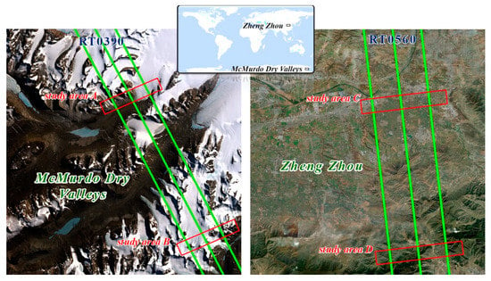
Figure 1.
ICESat-2 laser ground tracks in McMurdo Dry Valleys and Zheng Zhou. The red boxes in the study sites correspond to the detailed terrain matching results in Section 4 (as illustrated in Figure 7).
The horizontal accuracy of the DSM in the study sites should have better accuracy than the laser altimetry to reduce the possibility of mismatch. The airborne lidar data of the MDV were collected [21] with an Optech Titan multispectral sensor during the summer of 2014–2015. The vertical and horizontal accuracy is estimated at 0.07 and 0.03 m, respectively. The high-accuracy lidar data were made available via the OpenTopography platform. The airborne lidar was used to obtain the surface data of Zhengzhou in 2018. The data resolution is 1 m, and the coverage is ~5000 . The specific study sites’ parameters are illustrated in Table 1.

Table 1.
Introduction of research sites’ parameters.
2.2. ICESat-2 Data
ICESat-2 can obtain dense photons with 0.7 m spacing in the along-track direction from a 496 km orbit [22]. The satellite obtains laser data on a 91-day repetition period, with an orbital inclination of 94°. The observation coverage range is 88°S–88°N, which achieves global coverage. The onboard ATLAS can send a single laser pulse to the ground at a repetition frequency of 10 kHz [23]. Figure 2 shows the beam pattern on the ground. The pattern has a total of six laser beams organized in a 3 × 2 array. Each beam pair consists of a strong and a weak beam with an energy ratio of 4:1. The generated laser tracks are 3.3 km apart and 90 m wide between the strong and weak beams. The beam intensity depends on the orbital direction of the satellite. In the along-track direction, the strong beam maps to the right orbit (R), the weak beam maps to the left orbit (L), and vice versa.
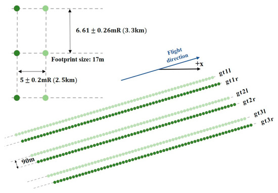
Figure 2.
The sampling geometry of ICESat-2 [23]. By yawing the spacecraft slightly, the beam pattern, which is an array, generates three pairs of beams on the ground. The planned spacing of each beam is 90 m, but the spacing can be changed by adjusting the yaw angle on the orbit.
ICESat-2/ATLAS data products are divided into five levels, which contain 21 standard data products from ATL00 to ATL21. The publicly available products are obtained from the NASA Distributed Active Archive Center (DAAC) at the National Snow and Ice Data Center (NSIDC). The ATL03 product provides each photon’s longitude and latitude, elevation, and measurement time, as well as relevant parameters such as photon confidence labels and elevation correction information [7]. Additionally, it also includes a set of parameters that are useful for higher-level user-oriented products, such as the rough distinction between signal and noise, surface classification of land, ocean, land ice, sea ice, and inland waters, several geophysical corrections for photon heights to account for tidal and atmospheric effects, measurements of the ATLAS system impulse response function, and so on [24].
Here, the fifth version (labeled as V5) of the ATL03 product was adopted to train and validate results. Twelve tracks are selected, covering December 2018 to July 2022. The specific track information chosen is shown in Table 2. Due to time-dependent distance deviation, the V5 data update some product parameters by adding the ATL03 photon height correction reference value. The relevant data on the website (https://search.earthdata.nasa.gov, accessed on 22 November 2022) are free to access.

Table 2.
ICESat-2 data in this study. The data of two laser ground tracks passing through the study site at different times are selected, respectively. RGT0390 corresponds to MDV, and RGT0560 corresponds to ZZ.
3. Method
Because of the oscillation of photons in the air, laser trajectory would be deformed when it reaches the ground, and simple translation parameters are not enough to describe it accurately. The two-dimensional affine transformation model can effectively describe the deformation of the GTs caused by various factors, such as alignment errors and laser on-orbit time-varying pointing deviation. Therefore, a two-step terrain matching method is adopted. Firstly, a rough matching is performed using a pyramid iterative search algorithm which quickly obtains the approximate position of the GTs through layered search and provides an initial value for precise matching. Subsequently, an iterative matching method based on high-accuracy terrains is proposed, which refines the parameters of the affine transformation model of the GTs using the least square method, obtaining the position with the minimum elevation difference between laser photons and the high-accuracy DSM.
The flowchart of the proposed method is shown in Figure 3, including signal photon extraction, rough matching, and precise matching. The official confidence label and the quadtree isolation (QI) noise removal method is used to preprocess the ATL03 data to obtain high-quality signal photons. The two-step terrain matching method is then employed to correct the photon coordinates. The proposed algorithm considers the deformation of GTs in rotation and scaling scales, thus having the potential to achieve more accurate matching positions between laser photons and the reference terrain.
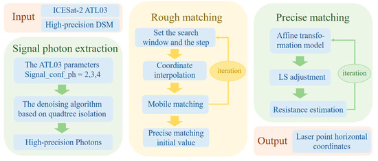
Figure 3.
Flowchart of the proposed terrain-matching method.
3.1. Signal Photon Extraction
ATLAS uses a high-sensitivity photon-counting system. It is easily affected by solar background noise, atmospheric scattering noise, and instrument noise [25]. Noise photons are widely distributed, so extracting signal photons from raw data is challenging. The result of signal photon extraction directly affects the follow-up steps [26]. Most proposed noise removal methods are based on spatial distribution characteristics, which are not friendly enough for users [27,28,29,30]. Photons’ local density distributions differ considerably by observing the raw data, signal, and noise. Signal photons are densely distributed, while noise photons are more sparsely scattered.
To avoid the influence of noise photons on the matching results, we use the signal label in ATL03 data and quadtree isolation to participate in the signal photon extraction. The parameter is provided to users in ATL03 data to judge the confidence of photons. The value of −2, −1, 0 or 1 indicates that the photon is an independent, noise, or buffer photon. The value of 2, 3 or 4 indicates that the photon is a low-confidence, medium-confidence, or high-confidence signal. Therefore, the signal label in ATL03 data can be used to remove the obvious noise photons away from signals.
Zhang et al. [31] proposed a quadtree isolation noise removal method that employs a quadtree to partition each photon and determine each photon’s tree depth. The outliers are identified as photons with smaller tree depths. This method outperforms conventional noise removal methods in accuracy. It does not rely on external parameter input and has yielded promising results in various terrain experiments. Therefore, quadtree isolation can be used to accurately remove the remaining noise photons. The photon denoising result is shown in Figure 4.

Figure 4.
Photon denoising results for ATL03_20211018005010_03901312_005_01 within the latitude range of −77.68° to −77.67°. For ICESat-2 ATL03 products, noisy geolocated photons (red points) were measured by self-contained parameters, noisy geolocated photons (green points) were detected by the quadtree noise removal method and the detected signal photons (blue points). The x-axis represents the latitude, and the y-axis represents the photon height.
3.2. Rough Matching
The conventional pyramid iterative search method roughly matches the laser photon tracks. It provides an initial value for the following least square iteration. Figure 5 shows the diagram of the rough matching method.
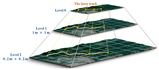
Figure 5.
Schematic diagram of the rough matching method. The yellow curve is the laser ground track. The rough matching method is set for two searches, and the search step is 1 and 0.2 m, respectively.
Two levels of pyramid search are set up, with a search step of 1 and 0.2 m, respectively. When searching each layer, a bilinear interpolation method is used to obtain DSM elevation values corresponding to ground photons. The best matching position is determined by calculating the ground laser and DSM correlation coefficient. Then, the next layer is searched. Once the step size is determined, we can obtain the corresponding matching coordinates and , along with the ground elevation value :
where is the number of times the laser track moves within the search window with the value of . The coordinate with the maximum correlation coefficient is selected as the result of rough matching:
where is the matching correlation coefficient between the laser photon track and topographic profile, is the number of photons in the laser track, and is the elevation values from ATL03 data. The search area is traversed to determine and with the highest correlation coefficient. The result of rough matching provides initial values for photon coordinates in precise matching. This not only reduces the time required for terrain matching, but also avoids getting trapped in local optima during the iterative process.
3.3. Precise Matching
In Section 3.2, the approximate location of matching between ground track and terrain profiles is determined, but the accuracy is not high enough due to the former step’s limitation. Photons oscillate in the air, leading to the laser track’s deformation. Simple translation parameters are not sufficient to describe these complexities. Therefore, a two-dimensional affine transformation model is developed, which contains rotation and scaling factors to describe the photon track’s deformation accurately. Then, the model parameters are optimized by the least square iteration to obtain more accurate terrain-matching results. The schematic representation of the iterative matching method based on high-accuracy terrains is shown in Figure 6.
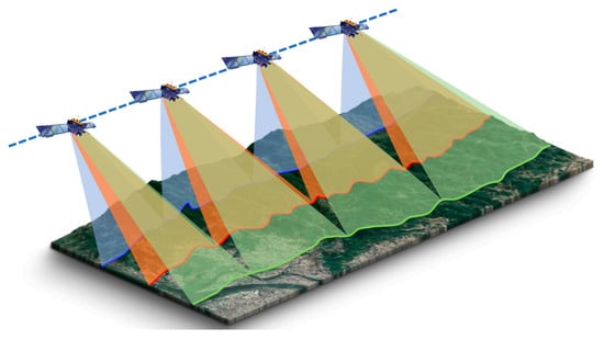
Figure 6.
Schematic diagram of the precise matching method. The affine transformation model of Equations (4)–(6) expresses the laser ground tracks. By iteratively modifying the model parameters, the optimal match between tracks and terrain profile is obtained.
The affine transformation model is constructed using photon coordinates obtained by rough matching:
where and () are the parameters of the affine transformation model, and and are the photons positions obtained after the rough match and the precise match, respectively.
Considering the deformation of elevation value and geometric distortion of the topographic profile, the elevation of the precise matched ground track can be written as:
where and are the elevation values of photons before and after matching, respectively, is the translation of the elevation, and is the scaling factor.
The amount of difference before and after matching can be expressed as follows:
We perform Taylor processing on the expression and keep the first term as follows:
Therefore, the error equation of the photon’s least square track matching can be listed as:
The unknown parts are the correction values of various undetermined parameter values, and the initial value is given as follows: .
The constant term is:
The signal photon extraction method cannot completely remove noise photons. The remaining noise photons can affect the results of least square adjustment, making it challenging to achieve the best matching between laser tracks and reference terrain. The robust estimation is introduced, and an appropriate equivalent weight matrix is chosen to replace the prior weight matrix. We ultimately choose the Tukey function by comparing the ability of different equivalent weight functions to suppress noise photons [32]. The specific experiments are described in Section 5.3.
The Tukey function is:
where is the weight of the error equation of the photon calculated by the Tukey function, and is the standard error of the mean.
If the number of photons involved is , the equivalent weight matrix is obtained as follows:
Therefore, the solution of the equation can be written as
where is the constant vector of each photon calculated by Equation (10), , .
The adjustment results are used to correct the parameters of the affine transformation model, and Equations (4)–(13) are repeated until the difference between the two iterations is less than a threshold value.
4. Results
4.1. Terrain Matching
As shown in Figure 7, the elevation difference between most photons and the reference terrain is more than 2 m. Our method significantly improves the consistency between the corrected laser ground track and the reference DSM, indicating that most horizontal errors have been eliminated.

Figure 7.
The elevation difference between the signal photon heights for each ICESat-2 pulse and the corresponding reference DSM before and after terrain matching. The blue line indicates the difference smoothed by a moving average filter with a 20 m window. The grey points represent the elevation difference of each photon. The study sites corresponding to (a–d) are the red boxes marked in Figure 1.
In Figure 8, most of the ATL03 photons are below the terrain profile before matching. The absolute value of the height difference between more than 80% photons and the reference terrain can be reduced to less than 1.5 m after coordinate correction. For RGT0390, the mean absolute value (MAV) before and after matching is 1.04 m and 0.64 m, respectively. For RGT0560, the MAV before and after matching is 2.64 m and 2.15 m. The matching of laser tracks and reference terrain in MDV shows better consistency.
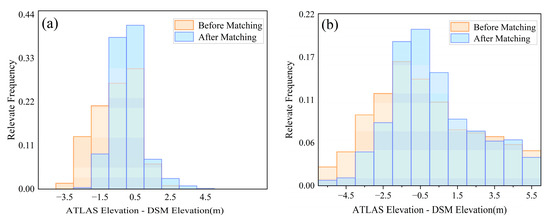
Figure 8.
The elevation difference distribution between laser photons and the reference terrain. (a,b) correspond to MDV and ZZ, respectively.
The detailed values of the geolocation errors of laser ground tracks are listed in Table 3. After coordinating correction, the standard deviation (STD) of elevation difference between the photon and the reference terrain decreased by 14.27% and 14.61% in the MDV and ZZ, respectively. The RMSE dropped by 20.99% and 25.00%, respectively. Although the laser tracks in ZZ showed significant improvement, they still have higher STD and RMSE. It can be attributed to the complex vegetation cover, which reduces the geographic positioning accuracy of photons. A large area of exposed rock covered by MDV leads to more accurate matching results.

Table 3.
Detailed values of the geolocation errors of ICESat-2.
To further evaluate the effectiveness of our method, we use two alternative methods in the same study site to make a comparative study. Tang’s method utilizes the pyramid iteration method [13]. It determines the window and step sizes according to the terrain characteristics to determine the minimum elevation difference of DSM and improve the geolocation accuracy. Schenk’s method constructs the minimum area element [17]. It uses the least square iteration method to estimate the distance and minimum elevation from the photon to the minimum area element. Notably, both methods treat the laser photon track as a whole, which differs from ours. Figure 9 gives the comparison and verification results of the three terrain-matching methods.
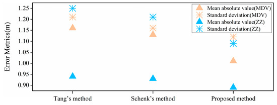
Figure 9.
Selection of the same laser ground tracks to compare the matching results of three methods.
By comparing the matching results calculated by the three methods, it is not difficult to find that the proposed method can accomplish the best matching between photons and the reference terrain. The lower MAV and STD indicate that considering the deformation of laser tracks in terrain matching is necessary.
4.2. Assessment of ICESat-2 Data Accuracy
Initially, 814 laser ground sets are selected, including 582 in MDV and 232 in ZZ. To ensure data quality, we kept 673 sets with high SNR, less affected by clouds and fog. As shown in Figure 10, the statistics are presented as the average offset after matching different beams.
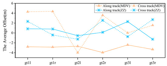
Figure 10.
Offset of laser photon pulses in the direction of along and cross track.
Due to the high accuracy of the selected DSM data (better than 1 m), the average offset can be used as its horizontal error. The average horizontal accuracy of the ICESat-2 laser tracks in MDV and ZZ is 3.86 m and 4.67 m, respectively. The horizontal accuracy of the whole dataset is less than 5 m, which is far lower than the theoretical positioning accuracy requirement of 6.5 m specified in official documents. Additionally, the offset variations along the track direction of different beams are stable. The offset across the track is relatively large, caused by the laser altimetry’s working mode. Table 4 shows that the results obtained by the proposed method are the same as those obtained by the other two methods. This consistency further proves the effectiveness of the proposed method.

Table 4.
Comparison of terrain-matching results from different methods.
5. Discussion
5.1. Assessment of ICESat-2 Geolocation Errors
As mentioned in Section 1, our aim is to evaluate the geolocation accuracy and accuracy of ICESat-2 observations. Wang et al. [5] and Liu et al. [33] considered that slope and SNR are the primary factors that affect the positioning accuracy of ICESat-2. The satellite’s flight state constantly changes during operation, and the photon density is affected by the time difference between day and night. These factors can also affect photon positioning. Therefore, using slope, SNR, latitude, and photon density as input features, a random forest model is developed to determine the relative importance of each factor.
The RF model performed well in multivariate data analysis. The increased mean square error percentage (%IncMSE) provided by it can effectively reflect the relative importance of different variables [34]. The %IncMSE is the average increment of the contribution of a variable to the mean square error divided by the variability. The higher the %IncMSE, the more crucial the variable. It is worth noting that due to the limited explanatory power of the regression model, we mainly focus on ordering the variable %IncMSE values rather than their proportions [35]. Figure 11 indicates that slope is the primary factor affecting the positioning accuracy of ICESat-2, followed by SNR. Latitude and photon density can also have little impact on location accuracy.
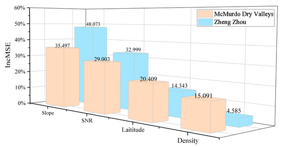
Figure 11.
Relative importance (measured as %IncMSE) of factors in the geographical positioning accuracy. Variables with larger %IncMSE values are more crucial.
5.2. Slope
Geographical positioning error caused by slope is regarded as one of the most significant error sources in LiDAR surveys, as terrain undulations can cause deviations in laser echo signals [36]. To verify the influence of slope on the positioning of ICESat-2, we count the slope corresponding to laser tracks in MDV and ZZ and draw box plots with 5° divisions, as shown in Figure 12. It is worth noting that due to the steep terrain of the MDV, 0–10° is merged for the convenience of analysis.

Figure 12.
Statistics of STD of elevation difference between photons and reference terrain under different slopes. The blue point represents the elevation difference between each photon and the reference terrain. The blue line corresponds to the normal distribution curve. Moreover, (a,b) correspond to MDV and ZZ, respectively.
As the slope increases, the STD between the photons and reference terrain increases significantly. When the slope is less than 10°, the STD is low, and the distribution of photons’ elevation difference is concentrated. This indicates that the photon quality is higher at lower slopes. The large terrain slope can alter the path of photon reflection, thus affecting the photon’s positioning accuracy. As a result, future research should prioritize eliminating coordinate errors caused by slope in ATL03 data.
5.3. SNR
According to the random forest results in Section 5.1, SNR is also a crucial factor that affects the positioning accuracy of ICESat-2. Since the laser pulses of the ATLAS system are weak signals, distinguishing the reflected pulses from atmospheric scattering, solar radiation, and the instrument’s noise on the target object’s surface can be challenging. The significant background noise seriously impacts the accuracy of terrain-matching. Although the quadtree segmentation method has been used for photon denoising during data pre-processing, the noise photons cannot be removed completely. To enhance the method’s robustness, we add robust estimation during the least square iteration and select the appropriate estimation method to avoid the influence of gross error on the affine transformation model parameters that need to be solved.
Robust estimation is used to reduce the influence of outliers on estimation results. It uses different equivalent weight functions to affect the adjustment result. The selection of weight functions is based on the relationship between each observation in the sample and the overall sample. The functions will assign higher weights to some observations in the sample, causing these observations to have a greater impact on the least square adjustment. To select a function suitable for our method, we compare the matching results of the Tukey function and the Huber function [37] with different SNRs.
The Tukey function is expressed in Equation (11), and the Huber function can be expressed as follows:
We select a laser photon track and add noise photons to compare the matching results with different equivalent weight functions. The matching result without noise photons is considered the true position of the laser track. As shown in Figure 13, without robust estimation, the matching result deviates significantly from the true position when the SNR is 5%. This indicates that noise photons can easily affect the least square method. As the SNR increases, the error of the matching result tends to be stable, and the RMSE remains around 1 m. After using the equivalent weight function, noise interference on the matching result is significantly suppressed in the case of fewer noise photons. Especially when the SNR is less than 10%, the suppression effect of the Tukey function is particularly obvious. The SNR of denoised data can be kept below 10%. This indicates that the adjustment result can effectively reduce the effect of noise photons after using robust estimation.
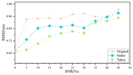
Figure 13.
Comparison of terrain-matching results from different equivalent weight functions.
6. Conclusions
In this study, we propose a new method for terrain matching to evaluate the geolocation accuracy of ICESat-2 laser altimetry observations. Unlike previous studies, we construct an affine transformation model for laser photon tracks and iteratively correct translation, rotation, and scaling parameters through least square matching to achieve the best match between the laser photon tracks and reference terrain. The method is tested with the ICESat-2 V5 data in McMurdo Dry Valley and Zhengzhou. The results in Section 4.1 show that this method can achieve better matching results. The STD of average elevation difference of MDV and ZZ decreased by 14.27% and 14.61%, respectively, and the RMSE decreased by 20.99% and 25.00%, respectively. Comparing the results of terrain matching, our method considers the deformation of laser tracks.
The average horizontal accuracy of the ICESat-2 laser tracks in MDV and ZZ is 3.86 m and 4.67 m, respectively, which meets the accuracy requirement of 6.5 m. We demonstrate through constructing a random forest model that slope and SNR are the key factors affecting the photon positioning of ICESat-2. Considering the sensitivity of the least square method, we introduce a robust estimation model to reduce the influence of noise photons on the matching results.
The terrain-matching method proposed in this paper can achieve ICESat-2 geolocation accuracy verification and provide a new method for calibrating satellite-based laser radar’s laser point and ranging system. However, this study still has certain limitations. Firstly, we only selected mid-latitude and high-latitude regions for experimentation. Future research will focus on verifying and analyzing the geolocation accuracy of ATLAS data in other parts of the world. Secondly, although we examined the impact of terrain slope on photon positioning, we have yet to propose a corresponding solution. Our next plan will focus on developing a correction model to improve the geolocation accuracy of ICESat-2.
Author Contributions
Conceptualization, M.G. and S.X.; methodology, M.G. and S.X.; software, M.G., S.X., G.Z. and X.Z.; validation, M.G., S.X., G.Z. and P.L.; formal analysis, X.Z.; data curation, G.Z.; writing—original draft preparation, M.G.; writing—review and editing, S.X., G.Z. and P.L. All authors have read and agreed to the published version of the manuscript.
Funding
This research was funded by the National Natural Science Foundation of China Projects (Grant No. 41876105, 41371436).
Data Availability Statement
The ICESat-2/ATLAS datasets provided in the article are available at https://search.earthdata.nasa.gov, accessed on 21 October 2022.
Acknowledgments
We thank the National Aeronautics and Space Administration (NASA) for providing the ICESat-2 data used in the article.
Conflicts of Interest
The authors declare no conflict of interest.
References
- Kääb, A.; Treichler, D.; Nuth, C.; Berthier, E. Brief Communication: Contending Estimates of 2003–2008 Glacier Mass Balance over the Pamir–Karakoram–Himalaya. Cryosphere 2015, 9, 557–564. [Google Scholar] [CrossRef]
- Zwally, H.J.; Schutz, B.; Abdalati, W.; Abshire, J.; Bentley, C.; Brenner, A.; Bufton, J.; Dezio, J.; Hancock, D.; Harding, D.; et al. ICESat′s Laser Measurements of Polar Ice, Atmosphere, Ocean, and Land. J. Geodyn. 2002, 34, 405–445. [Google Scholar] [CrossRef]
- Smith, B.; Fricker, H.A.; Gardner, A.S.; Medley, B.; Nilsson, J.; Paolo, F.S.; Holschuh, N.; Adusumilli, S.; Brunt, K.; Csatho, B.; et al. Pervasive Ice Sheet Mass Loss Reflects Competing Ocean and Atmosphere Processes. Science 2020, 368, 1239–1242. [Google Scholar] [CrossRef] [PubMed]
- Nie, S.; Wang, C.; Xi, X.; Luo, S.; Li, G.; Cheng, F. A Continuous Wavelet Transform Based Method for Ground Elevation Estimation Over Mountainous Vegetated Areas Using Satellite Laser Altimetry. IEEE J. Sel. Top. Appl. Earth Obs. Remote Sens. 2018, 11, 2945–2956. [Google Scholar] [CrossRef]
- Wang, C.; Zhu, X.; Nie, S.; Xi, X.; Li, D.; Zheng, W.; Chen, S. Ground Elevation Accuracy Verification of ICESat-2 Data: A Case Study in Alaska, USA. Opt. Express 2019, 27, 38168. [Google Scholar] [CrossRef] [PubMed]
- Luthcke, S.B. Reduction of ICESat Systematic Geolocation Errors and the Impact on Ice Sheet Elevation Change Detection. Geophys. Res. Lett. 2005, 32, L21S05. [Google Scholar] [CrossRef]
- Neumann, T.A.; Martino, A.J.; Markus, T.; Bae, S.; Bock, M.R.; Brenner, A.C.; Brunt, K.M.; Cavanaugh, J.; Fernandes, S.T.; Hancock, D.W.; et al. The Ice, Cloud, and Land Elevation Satellite—2 Mission: A Global Geolocated Photon Product Derived from the Advanced Topographic Laser Altimeter System. Remote Sens. Environ. 2019, 233, 111325. [Google Scholar] [CrossRef]
- Slobbe, D.; Lindenbergh, R.; Ditmar, P. Estimation of Volume Change Rates of Greenland′s Ice Sheet from ICESat Data Using Overlapping Footprints. Remote Sens. Environ. 2008, 112, 4204–4213. [Google Scholar] [CrossRef]
- Siegfried, M.R.; Hawley, R.L.; Burkhart, J.F. High-Resolution Ground-Based GPS Measurements Show Intercampaign Bias in ICESat Elevation Data Near Summit, Greenland. IEEE Trans. Geosci. Remote Sens. 2011, 49, 3393–3400. [Google Scholar] [CrossRef]
- Rowlands, D.D.; Carabajal, C.; Luthcke, S.B.; Harding, D.J.; Sauber, M.; Bufton, J.L. Satellite Laser Altimetry: On-Orbit Calibration Techniques for Precise Geolocation. Rev. Laser Eng. 2000, 28, 796–803. [Google Scholar] [CrossRef]
- Harding, D.J. ICESat Waveform Measurements of Within-Footprint Topographic Relief and Vegetation Vertical Structure. Geophys. Res. Lett. 2005, 32, L21S10. [Google Scholar] [CrossRef]
- Malambo, L.; Popescu, S.C. Assessing the Agreement of ICESat-2 Terrain and Canopy Height with Airborne Lidar over US Ecozones. Remote Sens. Environ. 2021, 266, 112711. [Google Scholar] [CrossRef]
- Tang, X.; Xie, J.; Gao, X.; Mo, F.; Feng, W.; Liu, R. The In-Orbit Calibration Method Based on Terrain Matching With Pyramid-Search for the Spaceborne Laser Altimeter. IEEE J. Sel. Top. Appl. Earth Obs. Remote Sens. 2019, 12, 1053–1062. [Google Scholar] [CrossRef]
- Brunt, K.M.; Neumann, T.A.; Smith, B.E. Assessment of ICESat-2 Ice Sheet Surface Heights, Based on Comparisons Over the Interior of the Antarctic Ice Sheet. Geophys. Res. Lett. 2019, 46, 13072–13078. [Google Scholar] [CrossRef]
- Nan, Y.; Feng, Z.; Liu, E.; Li, B. Iterative Pointing Angle Calibration Method for the Spaceborne Photon-Counting Laser Altimeter Based on Small-Range Terrain Matching. Remote Sens. 2019, 11, 2158. [Google Scholar] [CrossRef]
- Zhao, P.; Li, S.; Ma, Y.; Liu, X.; Yang, J.; Yu, D. A New Terrain Matching Method for Estimating Laser photoning and Ranging Systematic Biases for Spaceborne Photon-Counting Laser Altimeters. ISPRS J. Photogramm. Remote Sens. 2022, 188, 220–236. [Google Scholar] [CrossRef]
- Schenk, T.; Csatho, B.; Neumann, T. Assessment of ICESat-2′s Horizontal Accuracy Using Precisely Surveyed Terrains in McMurdo Dry Valleys, Antarctica. IEEE Trans. Geosci. Remote Sens. 2022, 60, 1–11. [Google Scholar] [CrossRef]
- Yao, J.; Tang, X.; Li, G.; Ai, B.; Yang, X.; Xie, D. Cloud Detection of Laser Altimetry Satellite ICESat-2 and the Related Method. Laser Optoelectron. Prog. 2020, 57, 131408. [Google Scholar] [CrossRef]
- Fountain, A.G.; Nylen, T.H.; Monaghan, A.; Basagic, H.J.; Bromwich, D. Snow in the McMurdo Dry Valleys, Antarctica. Int. J. Climatol. A J. R. Meteorol. Soc. 2010, 30, 633–642. [Google Scholar] [CrossRef]
- Fountain, A.G.; Levy, J.S.; Gooseff, M.N.; Van Horn, D. The McMurdo Dry Valleys: A Landscape on the Threshold of Change. Geomorphology 2014, 225, 25–35. [Google Scholar] [CrossRef]
- Fountain, A.G.; Fernandez-Diaz, J.C.; Obryk, M.; Levy, J.; Gooseff, M.; Van Horn, D.J.; Morin, P.; Shrestha, R. High-resolution elevation mapping of the McMurdo Dry Valleys, Antarctica, and surrounding regions. Earth Syst. Sci. Data 2017, 9, 435–443. [Google Scholar] [CrossRef]
- Abdalati, W.; Zwally, H.J.; Bindschadler, R.; Csatho, B.; Farrell, S.L.; Fricker, H.A.; Harding, D.; Kwok, R.; Lefsky, M.; Markus, T.; et al. The ICESat-2 Laser Altimetry Mission. Proc. IEEE 2010, 98, 735–751. [Google Scholar] [CrossRef]
- Markus, T.; Neumann, T.; Martino, A.; Abdalati, W.; Brunt, K.; Csatho, B.; Farrell, S.; Fricker, H.; Gardner, A.; Harding, D.; et al. The Ice, Cloud, and Land Elevation Satellite-2 (ICESat-2): Science Requirements, Concept, and Implementation. Remote Sens. Environ. 2017, 190, 260–273. [Google Scholar] [CrossRef]
- Neumann, T.; Brenner, A.; Hancock, D.; Robbins, J.; Saba, J.; Harbeck, K.; Gibbons, A. Ice, Cloud, and Land Elevation Satellite–2 (ICESat-2) Project: Method Theoretical Basis Document (ATBD) for Global Geolocated Photons (ATL03); National Aeronautics and Space Administration, Goddard Space Flight Center: Greenbelt, MD, USA, 2019. [Google Scholar]
- Ye, D.; Xie, H.; Tong, X.; Zhang, Z.; Li, M. The Comparison of Denoising Methods for Photon Counting Laser Altimeter Data. In Proceedings of the IGARSS 2019—2019 IEEE International Geoscience and Remote Sensing Symposium, Yokohama, Japan, 28 July–2 August 2019; pp. 8478–8480. [Google Scholar]
- Magruder, L.A.; Wharton, M.E.; Stout, K.D.; Neuenschwander, A.L. The Noise Filtering Techniques for Photon-Counting Ladar Data. In Proceedings of the Laser Radar Technology and Applications XVII, Baltimore, MD, USA, 23–27 April 2012; p. 83790Q. [Google Scholar]
- Yang, G.; Shu, R.; LI, M. An Adaptive Directional Filter for Photon Counting Lidar Point Cloud Data. J. Infrared Millim. Waves 2017, 36, 107–113. [Google Scholar]
- Zhu, X.; Nie, S.; Wang, C.; Xi, X.; Wang, J.; Li, D.; Zhou, H. A Noise Removal Method Based on OPTICS for Photon-Counting LiDAR Data. IEEE Geosci. Remote Sens. Lett. 2021, 18, 1471–1475. [Google Scholar] [CrossRef]
- Zhu, X.; Nie, S.; Wang, C.; Xi, X.; Hu, Z. A Ground Elevation and Vegetation Height Retrieval Method Using Micro-Pulse Photon-Counting Lidar Data. Remote Sens. 2018, 10, 1962. [Google Scholar] [CrossRef]
- Zhang, G.; Lian, W.; Li, S.; Cui, H.; Jing, M.; Chen, Z. A Self-Adaptive Noise removal method Based on Genetic Method for Photon-Counting Lidar Data. IEEE Geosci. Remote Sens. Lett. 2022, 19, 1–5. [Google Scholar] [CrossRef]
- Zhang, G.; Xu, Q.; Xing, S.; Li, P.; Zhang, X.; Wang, D.; Dai, M. A Noise-Removal Method Without Input Parameters Based on Quadtree Isolation for Photon-Counting LiDAR. IEEE Geosci. Remote Sens. Lett. 2022, 19, 1–5. [Google Scholar] [CrossRef]
- Wilcox, R.R. Introduction to Robust Estimation and Hypothesis Testing; Academic Press: Cambridge, MA, USA, 2011. [Google Scholar]
- Liu, A.; Cheng, X.; Chen, Z. Performance Evaluation of GEDI and ICESat-2 Laser Altimeter Data for Terrain and Canopy Height Retrievals. Remote Sens. Environ. 2021, 264, 112571. [Google Scholar] [CrossRef]
- Hastie, T.; Friedman, J.; Tibshirani, R. The Elements of Statistical Learning; Springer Series in Statistics; Springer: New York, NY, USA, 2001; ISBN 978-1-4899-0519-2. [Google Scholar]
- Louppe, G. Understanding Random forests: From Theory to Practice. arXiv 2015, arXiv:1407.7502. [Google Scholar]
- Urbazaev, M.; Hess, L.L.; Hancock, S.; Sato, L.Y.; Ometto, J.P.; Thiel, C.; Dubois, C.; Heckel, K.; Urban, M.; Adam, M.; et al. Assessment of Terrain Elevation Estimates from ICESat-2 and GEDI Spaceborne LiDAR Missions across Different Land Cover and Forest Types. Sci. Remote Sens. 2022, 6, 100067. [Google Scholar] [CrossRef]
- Maronna, R.A.; Martin, R.D.; Yohai, V.J.; Salibián-Barrera, M. Robust Statistics: Theory and Methods (with R); John Wiley & Sons: Hoboken, NJ, USA, 2019. [Google Scholar]
Disclaimer/Publisher’s Note: The statements, opinions and data contained in all publications are solely those of the individual author(s) and contributor(s) and not of MDPI and/or the editor(s). MDPI and/or the editor(s) disclaim responsibility for any injury to people or property resulting from any ideas, methods, instructions or products referred to in the content. |
© 2023 by the authors. Licensee MDPI, Basel, Switzerland. This article is an open access article distributed under the terms and conditions of the Creative Commons Attribution (CC BY) license (https://creativecommons.org/licenses/by/4.0/).