Article

3D Discrete Fracture Network Modelling from UAV Imagery Coupled with Tracer Tests to Assess Fracture Conductivity in an Unstable Rock Slope: Implications for Rockfall Phenomena

1
Scuola di Scienze e Tecnologie, Sezione di Geologia, Università di Camerino, Via Gentile III da Varano, 62032 Camerino, Italy
2
Dipartimento di Scienze, Ingegneria della Materia dell’Ambiente ed Urbanistica (SIMAU), Università Politecnica delle Marche, Via Brecce Bianche 12, 60131 Ancona, Italy
3
Dipartimento di Scienze Pure e Applicate, Università degli Studi di Urbino Carlo Bo, Campus Scientifico Enrico Mattei, Via Cà le Suore, 2/4, 61029 Urbino, Italy
*
Author to whom correspondence should be addressed.
Remote Sens. 2023, 15(5), 1222; https://doi.org/10.3390/rs15051222
Submission received: 19 January 2023 / Revised: 13 February 2023 / Accepted: 20 February 2023 / Published: 22 February 2023

Abstract

:
The stability of a rock slope is strongly influenced by the pattern of groundwater flow through the fracture system, which may lead to an increase in the water pressure in partly open joints and the consequent decrease in the rock wall strength. The comprehension of the fracture pattern is a challenging but vital aspect in engineering geology since the fractures’ spatial distribution, connectivity, and aperture guide both the water movement and flow quantity within the rock volume. In the literature, the most accepted methods to hydraulically characterise fractured rocks in situ are the single borehole packer test, the high-resolution flow meters for fractures, and the artificial tracer tests performed in boreholes. However, due to the high cost a borehole requires and the general absence of wells along coastal cliffs, these methods may not be appropriate in rockfall-prone areas. In this study, an unsaturated rocky cliff, strongly affected by rockfalls, was investigated by combining kinematic analysis, Discrete Fracture Network (DFN) modelling, and artificial tracer tests. The DFN model and potential rock block failure mechanisms were derived from high-resolution 3D virtual outcrop models via the Structure from Motion (SfM) photogrammetry technique. An artificial tracer was injected using a double ring infiltrometer atop the recharge zone of the slope to determine the infiltration rate and validate the DFN results. The DFN and tracer test methods are frequently used at different spatial scales and for different disciplines. However, the integration of digital photogrammetry, DFN, and tracer tests may represent a new step in rockfall and landslide studies. This approach made possible the identification of groundwater flow patterns within the fracture system and revealed about a 10-day tracer transit time from the injection area and the monitored slope, with similar conductivity values gathered from both the DFN and tracer test. Planar and wedge failures with volumes ranging from 0.1 and 1 m3 are the most probable failure mechanisms in the areas. The results were consistent with the delay between the intense rainfall and the slope failures previously documented in the study area and with their mechanisms.

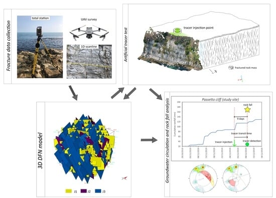
Graphical Abstract

1. Introduction

Fracture networks are the main path for groundwater within low-permeability rocks [1,2,3,4], which mainly depend on the hydraulic fracture connectivity [5,6], fracture geometrical parameters (e.g., length, aperture, roughness), and fracture distribution [7,8]. The role played by permeable discontinuities on the flow and transport is important both for the exploitation of geofluids (hydrocarbons, groundwater, and geothermal reservoirs) and the slope instability problems [9]. Modelling the groundwater circulation of a fractured rock media is fundamental to quantitatively characterise the fracture permeability for slope stability studies, since water is one of the triggering factors for rockfalls [10,11,12]. In fact, the development of high fluid pressure on fractures having a low shear strength is one of the potential causes for slope failure and the instability of underground openings, excavations, and slopes [13,14]. Due to the high importance that fracture networks have for engineering geology applications, a variety of methodologies for their conceptual understanding exist, including laboratory and field testing. Conventional geological data obtained by the scanline method on the outcrops are frequently used for the acquisition of fracture orientation, spacing, aperture, trace length, roughness, etc. [15,16,17,18]. The determination of internal rock mass fracturing can be undertaken through the study of borehole cores, geophysics, or statistical methods based on a surface fracture analysis. The borehole core analysis is a direct method for studying internal fractures and their characteristics. However, the cost associated with borehole drilling is relatively high, moreover, the study areas may be physically not accessible. On the contrary, indirect methods such as geophysical surveys can be used for defining the rock mass quality and fracture intensity, as demonstrated by Leucci et al. [19]. In the case of inaccessible or highly steep rock slopes, the use of remote sensing techniques can remarkably improve fracture data collected via traditional scan line methods, due to the flexibility of extracting data from digital outcrops and the good results gathered using stochastic DFN modelling for defining the fracture network properties from the surface to depth. Several studies are available in the literature on the manual and automatic structural analysis of discontinuities from virtual outcrops created using laser scanning or photogrammetry techniques [20,21,22,23,24,25,26]. The 2D/3D digital-based outputs (i.e., photorealistic 3D surfaces, dense point clouds, and orthomosaics) can be used to calculate the fracture spacing [23,27,28], connectivity [29], and size [30,31,32,33]. It must be noted that in high steep rock slopes, the use of the terrestrial laser scanner technique can have some limitations related to the distance from the target and occlusions [34]. In the survey of coastal cliffs, sometimes the use of this technique has become even more complicated or impossible due to the sea [23]. For these reasons, in recent years, technological advances in unmanned aerial vehicles (UAV) are increasingly used for building high-resolution 3D outcrop models via Structure-from-Motion, multi-view stereo photogrammetry (SfM-MVS) [35,36,37]. In this study, we proposed a method for the analysis of the fracture-driven groundwater flow direction in a sea rocky cliff in central Italy, which is interested by frequent rockfalls. Fracture network characteristics were determined by combining field geomechanical analyses (scanlines) with 3D digital outcrop models from UAV imagery and fracture analyses [38,39,40,41]. A 3D Discrete Fracture Network (DFN) model was created using the MOVE software (Petroleum Experts Ltd., Edinburgh, UK) to recreate the fracture distribution of rock mass [42,43,44,45,46,47,48,49] and calculate the fracture conductivity, which was validated with the artificial tracer test results.
The novelty of this method lies in the combined use of the UAV-extracted DFN model and tracer tests, carried in the unsaturated zone, which is conveyed through the soil using double ring infiltrometer equipment located atop the cliff. The tracer arrivals were monitored through specially selected traps of activated charcoal placed in the fracture planes. Conversely from the conventional methods usually used in the literature (i.e., hydraulic test in boreholes, active conduits, pressure response tests, air injection, etc.) [50,51,52,53,54], this method allows for important considerations regarding the time lag between heavy rainfall and rock collapses, which are derived from a historical analysis of the rockfall and rainfall events. In addition, the tracer tests allowed also for the validation of the hydraulic conductivity calculated by the DFN and to identify a priori (with an inexpensive analysis) hydraulically isotropy or anisotropy in the rock volume, as well as the flow direction.

2. Geological and Geomechanical Outlines of the Study Site

The study site is located on the coastal cliff of Ancona city (Marche Region, central Italy), which extends for 15 km between Ancona city and Numana village (Figure 1). This stretch of the coast is part of the Adriatic Sea coast, for which more than 766 landslides have been documented over a length of 370 km [55], involving different kinds of materials and movements. In this area is present the Conero Mt. (572 m a.s.l.), an active cliff with different types of instability phenomena [56]. The coastal area is characterised by steep cliffs with an average height usually higher than 100 m a.s.l. These cliffs developed mainly on the Schlier geological formation (Lower Messinian–Burdigalian, Umbria-Marche stratigraphic sequence [57]), which is constituted by alternances of low permeability marlstones and calcareous marlstone with varying percentages (35–80%) [23], lying as a monocline gently W–SW dipping (dip angle = 30° ÷ 35°). From a tectonic point of view, the area near Ancona city is characterised by faults and folds with a NW–SE trend (in accordance with the direction of the Apennine belt), and by transversal tectonic lines that cut the compressive structures. The heavy jointing characterising the rock masses outcropping in the area represents the recent tectonic activity of the transversal structures (with SE–NW trend). As reported by Casagli et al. [58], the present geomorphological features of the area are the result of marine erosion combined with the structural-lithological features and the Pleistocene tectonic history, which caused the formation of sub-vertical slopes subjected to selective erosion on the weakest levels. From a geo-mechanical point of view, the previous studies [56,58] highlighted the low strength of the intact rock material (Ϭc = 5 ÷ 50 MPa), which depends on the calcium carbonate content and accounts for the possibility of fresh shear failure in the rock mass. The main weakness zones are represented by discontinuities, which may lead to planar/wedge sliding and toppling failure [23]. Three or more joint sets are present [23,58], which lead to the formation of blocky to very blocky rock masses. From a hydrogeological standpoint, the Schlier Fm. is considered as an aquitard due to its very low primary permeability [59]. Therefore, a groundwater body is not present in the area which is under a general unsaturated condition. However, in the stretch of the coastline examined, few localised areas are subjected to drip water occurrence at the base of the sea cliff.

3. Materials and Methods

The approach developed in this research combines the discrete fracture network modelling with the in situ hydrological investigation, in which an artificial tracer was injected at the top of the cliff and monitored at its base through activated charcoal traps placed into the fractures. The field- and digital-based fracture data have been collected and processed to create a DFN model representative of the study area.

3.1. Conventional and UAV-Based Geomechanical Survey

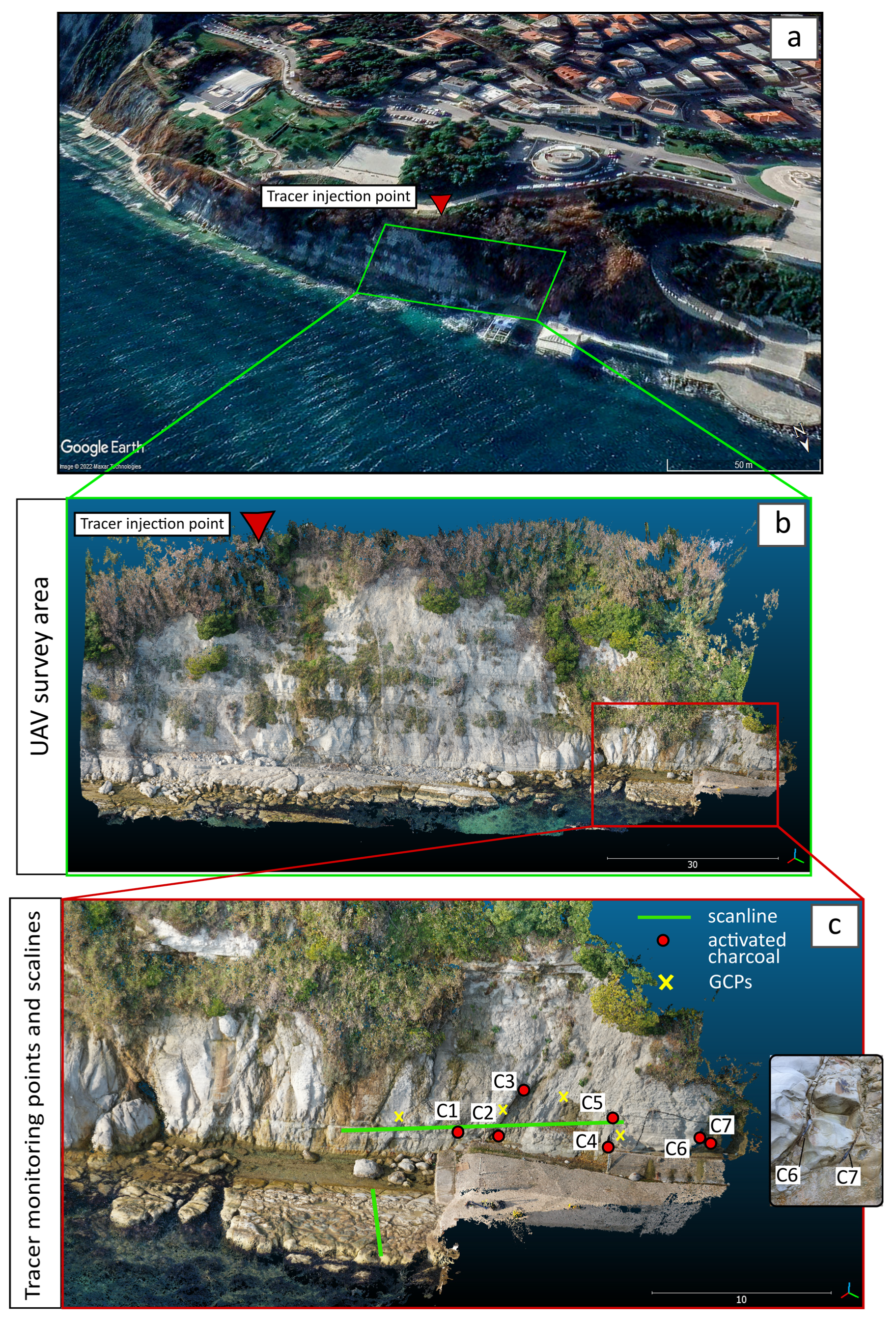
Geomechanical data of the cliff area (Figure 2) were gathered through the combined use of conventional and UAV surveys. Due to the sea level, only a few sectors of the cliff were accessible for conventional geomechanical surveys, consisting of two orthogonal scanlines with 6 and 12 m lengths (Figure 2c). The fracture parameters gathered from the conventional geomechanical survey were the following: distance from the scanline origin, orientation (dip azimuth and dip angle), mechanical aperture, trace length, the presence/absence of infilling material, and the joint roughness coefficient (JRC). The JRC was measured through the Barton’s profile–aperture comparator [60]. The mechanical apertures were measured using the comparator proposed by Ortega et al. [61]. In order to obtain the stochastic parameters for the DFN model, the fractures’ orientations were corrected using the Terzaghi approach [62] and grouped into discontinuity sets through a contour plot. Accordingly, the average normal spacing, average mechanical aperture, and trace length for each fracture set were determined. Moreover, the Fisher K value [63], expressing the variability of the orientation within the set, was calculated. The stereographic projections and kinematic analysis through Markland’s test were made using the Rocscience Dips software [64].
The UAV flight was undertaken to survey inaccessible sites of the cliff and extract 3D virtual outcrop models of the whole study area. In Figure 2b,c the areas studied through UAV and conventional surveys, respectively, are represented. A Mavic 2 Pro drone was used for the survey, equipped with the following camera characteristics: 20-megapixel camera resolution, 28 mm focal length with f/2.8 to f/11 aperture, and a maximum image size of 5472 × 3648 px. Due to its closeness to the cliff, the UAV was flown using the manual mode. Photographs were taken from an average distance of 20–30 m from outcrops so as to extract a high-resolution 3D model of the cliff. The subvertical cliff surface was acquired through multiple vertical photographic strips while the toe of the cliff was acquired through oblique and nadiral photograph acquisitions. In both cases, the side and frontal overlap was kept at about 70–80% and a total of 400 photographs were acquired. Ground Control Points (GCPs), necessary for the orientation of photographs and the creation of the 3D model, were measured though a Trimble S7 Total Station. More precisely, natural features easily visible on the cliff and on the UAV photographs (i.e., fractures, bolt, etc.) were captured and used as GCPs during photographs post-processing. A total of eighteen GCPs were measured. Total station data were referenced through a GPS survey, undertaken using a Trimble R8 GPS. The GPS’s measurement accuracy was about 2 cm (using RTK mode). An example of the GCPs acquired on the slope cliff is presented in Figure 2c.
UAV photographs and GCPs were managed and post-processed using the Structure-from-Motion (SfM)-based software Agisoft Metashape. Agisoft Metashape is a software specially developed to perform the photogrammetric processing of digital images and it generates 3D spatial data that can be used in different fields such as GIS applications, rock-mechanics, archeology, cultural heritage, etc. In this case, the software allowed for the reconstruction of a 3D model and orthophotos of the cliff and cliff toe (Figure 2c).

3.2. Fracture Analysis, 3D DFN Modelling and Cliff Kinematic Assessment

The orthophotos and 3D models extracted from the UAV survey were used to set up sampling windows in two different areas of the cliff. The discontinuities identified in these sampling windows through the NetworkGT toolbox for ArcGis [29] were used to determine the fracture intensity parameter (P21—expressed as the length of fracture per unit area) [65], and fracture network connectivity [66] (small scale centimeter/millimeter fractures were not taken into account). NetworkGT performed the topological analysis of the identified discontinuities, providing essential information on the fracture network. Regarding the fracture intensity, conversely from the conventional methods used for its determination, which rely on the calculation of the total length of fractures over the total area of the sampling window, NetworkGT provided the possibility to define multiple P21 values of several test circles and calculate an average value and its standard deviation. In addition to the P21 value, the connectivity value was calculated by averaging several test circles for each sampling window (for details see [29]). In this case, a total of 18 test circles for each sampling window was used for the calculation of the P21 and connectivity values. The result of the connectivity analysis provided lines, nodes, and branches between nodes for which a connectivity value could be calculated for each test circle [66]. Based on the P21 values, 3D DFN model were set up using the MOVE™ software (academic license provided by Petroleum Experts Ltd. to the University of Camerino) [67]. In a DFN, the fractures are idealized as a thin conductive layer of which the conductivity depends on the fracture aperture. The DFN model represents the background tectonic deformation (host rock fractures) and is designed for rocks with negligible matrix porosity, in which the permeability is provided exclusively by the fracture pattern. In this way, a value of zero was assigned by the software to the portions of the rock volume that were not crosscut by any fracture. For each fracture set, the model considered the following input data: the orientation (expressed as dip azimuth, dip angle, and Fisher K value), aspect ratio (height/length), length distribution, hydraulic aperture, and the volumetric fracture intensity (P32) [68]. An aspect ratio of 2 was assumed according to [69,70,71]. The hydraulic aperture was determined based on the mechanical aperture measured in the field, using the equation from [72]. The DFN model was developed using a 12 × 12 m box. The volumetric fracture intensity (P32: fracture area/unit volume), widely accepted as the preferred measure of fracture intensity, was derived by an iterative approach. The DFN models were developed using random P32 values. In such models, the average P21 of each fracture set was calculated through several 2D pseudo-scanlines (cross sections of the 3D DFN model). An example of one pseudo-scanline extracted from the DFN model and used for a P21 calculation is reported in Figure 3. The P32 values, and consequently the DFN models, were iteratively changed until the P21 extracted from the DFN matched the ones measured in the field.
Finally, to understand the potential kinematic of rock block failures, a further kinematic analysis was carried out. The RocScience Dips software was used for this purpose. Fracture data used for the analysis were retrieved from geomechanical and UAV surveys, while the cliff orientation was extracted from a UAV 3D model.

3.3. Hydrological Investigation

An artificial tracer test was performed starting from 25 February 2022, consisting of a release of 20 g of Na-Fluorescein (C20H10Na2O5) on the top of the rock cliff. The advantages of using the fluorescein as a tracer in geological studies was reported in [73]. As described in several studies [74,75,76], fluorescein has a low tendency to sorb, in respect to rhodamine. Fluorescein is safe to use, is stable and conservative over time, and it will not break down if exposed to direct sunlight [77,78]. The novelty of the injection method proposed in this study is that the Na-Fluorescein was put directly into the soil using a stainless-steel double ring infiltrometer, since active conduits and/or boreholes were not present in the top of the cliff area. This method promoted the release of the tracer from the topsoil (thickness ≈ 0.8 m) towards the underlying rock mass and, at the same time, permitted the calculation of the hydraulic conductivity of the topsoil, in which the meteoric recharge and infiltration processes took place. The time elapsed to cross the topsoil was then calculated, starting from the topsoil thickness and the infiltration rate. In detail, the selected quantity of tracer was dissolved in 30 L of deionized water and released in the inner ring, then four water-refilling operations with deionized water were conducted to ensure that all the tracer was leached from the double ring. The release operation was carried out in about 30 min; the water level within the inner ring was continuously monitored (data record frequency = 1 s) by means of a hydrometric pressure transducer (Diver Eijkelkamp, accuracy ±0.5 cmH2O and resolution 0.2 cmH2O) compensated by atmospheric pressure. The tracer injection was followed by a moderate rainfall event (i.e., 7.5 mm of rain in the following 4 h). On 26 February 2022, a further intense rainfall event (36 mm/day) fostered the tracer infiltration. Before the injection, seven activated charcoal traps were placed within the fracture planes with the aim of fixing the tracer passing within the discontinuities. To efficiently place the activated charcoal inside the fractures, avoiding water flow perturbation, traps made of PVC net containing the activated charcoal were specially designed. Details about the tracer monitoring points and the tracer injection location are reported in Figure 2c. The monitored points were slightly shifted northwards with respect to the release point due to the impracticality of physically reaching the cliff below the injection point. The tracer traps were substituted every 2 days until 30 April 2022, to (i) detect the first and further tracer arrivals, to (ii) quantify a lag between the tracer arrivals and daily rainfall data, freely available from the Marche Region Hydrometeorological monitoring system (https://www.regione.marche.it/Regione-Utile/Protezione-Civile/Console-Servizi-Protezione-Civile/SIRMIP-online, accessed on 1 May 2022), and to (iii) highlight which fractures were strictly involved in water circulation. The time between the injection and the first arrival was used to calculate the permeability of the rock mass (K) knowing the distance between the release and the monitoring points. The fluorescein (where present) was extracted from the activated charcoals using a potassium hydroxide solution in methanol at Università Politecnica delle Marche WaterLab. Once collected, the solutions obtained by the extraction were analysed by a RF-6000 laboratory spectrofluorometer produced by Shimadzu Corporation (Milan, Italy). The calibration of the spectrofluorometer was performed using three concentration standards (10, 20, and 100 ppb) prepared using a drip water sample collected in the field at the base of the cliff, as a blank sample before the tracer injection. In addition, the rainfall data collected from 2014 to 2021 in the Ancona Regione pluviometric station were used to investigate a possible relation between intense precipitation events and the occurrence of rockfalls in the area.

4. Results

4.1. Fracture Analysis

The 3D model based on the UAV survey is reported in Figure 4a, while the stereonet resulting from the geomechanical scanline method survey and UAV model analysis is highlighted in Figure 4b. Photographs and GCPs data were managed through Agisoft Metashape to create the orthophotos and 3D model of the cliff (depth maps generation was performed through a mild filtering mode and more than 8 h of processing time). The accuracy used during this process was 5 mm and the mean square error that resulted during the orientation process (placing the 18 GCPs on photographs) has been estimated for the X, Y, and Z directions of 0.014, 0.013, and 0.004, respectively. The reprojection error in px was approximately 1. Following the guidelines proposed by James et al. [79] about the use of Structure-from-Motion Photogrammetry, two further tests were carried out through independent check measurements. In the first test, the distance between two GPCs was measured by the total station and the 3D UAV-extracted model. The second test was based on the comparison between the fracture orientation measured in the field with a geological compass and in the 3D model. Results of independent check measurements are reported in Table 1, highlighting the good correspondence between the UAV-extracted data and independent measurements.
The point cloud 3D model and the orthophoto were created with a spatial resolution of approximately 6000 pts/m2, with a total of 47,475,838 points and 3.81 mm/pix. From the stereonet of Figure 4b, three main joint sets, J1, J2, and J3 and the bedding planes S0 are identified (Figure 4b). Table 2 reports the results of the geomechanical survey highlighting the average orientation of the joint sets, Fisher values, fracture roughness, fracture trace length, and mechanical and hydraulic aperture (calculated using [72]). The bedding planes (S0) were tightly closed, thus they were assumed as negligible for the scope of the fluid flow; thus, they were not included in the following DFN modelling. The fracture intensity and connectivity were calculated in both the UAV-extracted sampling windows 1 and 2 to reduce potential fracture orientation bias (Figure 4a). As explained in Section 3.2, P21 values were utilised to develop/validate the DFN model. The DFN model was created using an iterative approach modifying the input P32 values until the P21 values matched the ones from the sampling windows. Values of P21 extracted from the sampling windows and DFN model and values of P32 obtained from the iterative approach are listed in Table 3. Figure 5a,b show the fractures used for the calculation of the P21 values in NetworkGT (with and without the orthophoto base map, respectively). Figure 5c,d highlight the DFN model developed after the iterative approach (Figure 5c) and the pseudo-scanline extracted from the DFN and imported in NetworkGT for the validation procedure (Figure 5d). It is possible to note how, after the above-mentioned iterative approach, the values of P21 gathered from the sampling windows tightly match the ones from the DFN (Figure 5b,d and Table 3). From the DFN model it was possible to extract the fracture conductivity (k), equal to 2.91 × 10⁻³ cm/s, and the potential block volumes, ranging from about 0.1 to 1 m3.
Regarding the connectivity analysis, this was again developed using the Software NetworkGT. The results of the analysis are reported in Figure 6. Figure 6a,b show the fracture analysis in sampling window 1 and the resultant connectivity values in the ternary graphs (it is important to remember that the analysis has been carried out in multiple 1 square meter areas for each sampling window and therefore different values of connectivity have been calculated for each window). Figure 6c,d show the same results for sampling window 2. Both the sampling windows present high connectivity values, with the sampling window 1 having the highest ones.
Finally, the results of the kinematic analysis, performed to highlight potential cliff failure mechanisms, is represented in Figure 7. Considering the cliff orientation extracted from the UAV model (Figure 8a), it is possible to see that the most probable failure mechanism is related to a planar failure along J3 or a wedge failure along J3 and J2 (Figure 7b).
This was also confirmed by evidence of past failures observed in the cliff-extracted UAV 3D model (Figure 8b).

4.2. Rock Slope Hydrodynamic Features Achieved from Tracer Test

Figure 9 claims the graphical results of the artificial tracer test performed in the area. The tracer infiltration in the topsoil was enhanced by the rainfall events that occurred between 25 February 2022, and 26 February 2022, with a total amount of about 45 mm. The first tracer arrival occurred after about 10 days from the injection and a significant tracer amount was detected only in the C3 and C6 tracer monitoring points, located in the fracture set J3. Further tracer arrivals were recorded in C6 twenty days from the injection and it was preceded by minor rainfall events about twelve days before (on 3 March and 4 March 2022). The last tracer arrival was observed on 12 April 2022, in C7 (located in fracture set J1), likely fostered by a recharge event that started twelve days before, on 30 March 2022, and continued until 9 April with a total amount of precipitation of about 27 mm. This analysis accounts for a good correlation between the rainfall events and water movement within the fracture media, pointing out a stationary delay of about ten–twelve days between the recharge processes and traced water outflow from specific fracture sets (i.e., j3 and J1).
Moreover, the novel injection operation performed by means of a stainless-steel double ring infiltrometer provided valuable information about the hydraulic conductivity (K) of the topsoil. In particular, the recharge mechanisms simulated through four refilling operations (Figure 10a) provided a mean K value of 5.65 × 10⁻² cm/s.
The 4° recharge simulation that was permitted to reach the saturated conditions of the topsoil and the measured data of water head vs. time have been analysed to obtain the hydraulic conductivity value under saturated conditions (Ksat) which is equal to 1.8 × 10⁻² cm/s.
The relationship between the cumulative infiltration (i) and time (t) (Figure 10b) was permitted to apply to Equation (1) of Philip [80]:
i t = S   t + A   t
where S is the sorptivity and is a measure of the soil’s ability to absorb water by capillarity, while A is a constant value related to the soil’s hydraulic conductivity (i.e., its permeability under saturated conditions). Knowing the values of t and I (measured during the recharge simulation), it was possible to calculate the unknown values of A and S using the method of least squares, which in turn allows for the infiltration rate to be determined under transient conditions using Equation (2) of Philip [80]:
v t = 0.5   S t + A
The infiltration rates (v) of the topsoil vary between 2.4 × 10⁻² and 1.8 × 10⁻² cm/s under saturated conditions.

5. Discussion

The method presented in this paper is based in the integration of different survey and analysis techniques, such as the hydrological tracer test method, UAV photogrammetry, and kinematic and DFN analyses. This study, carried out in a cliff located in the Adriatic Sea (Ancona, Italy), has proved useful in determining the fracture conductivity of unsaturated rock masses, which are affected by high erosion and rock slope instability.
Due to the inaccessibility of the study area, the use of UAV in this study has allowed to remarkably improve the information about slope and fracture geometries. Thanks to the 3D photogrammetric cliff model, it was possible to define the orientation of the slope and discontinuities, investigate the potential failure mechanisms through kinematic study, and generate orthophotos for the fracture intensity and connectivity analyses. Geomechanical data and kinematic analysis, in agreement with previous studies carried out by Mammoliti et al. [23], highlighted the presence of four discontinuity sets, with J3 prone to planar failures and wedge failures when it intersects the joint set J2. Such mechanisms have been documented in the study area by the authors during field surveys and reported in Figure 8b. The planar failure in Figure 7a occurred along fracture set J3, which has the highest trace length and fracture intensity values (Table 2 and Table 3), in which the first tracer arrival is observed after 10 days from the release. Figure 7b shows a wedge failure with J3 and J2 involved.
With regard to the calculation of fracture intensity and connectivity using UAV data, a similar approach in inaccessible coastal areas has been recently presented by He et al. [81] and Devoto et al. [82], who demonstrated the importance of using UAVs in understanding the coastal landslide behaviour in Cornwall (UK) and the Island of Malta, respectively.
It is also important to note that the possibility of increasing the amount and quality of data through UAV surveys had an important role in the creation of the DFN model. The geometrical fracture information and the fracture intensity were, in fact, essential in the definition and validation of such model. The importance of UAV data in the development of the fracture network was also investigated by Francioni et al. [83] and Tuckey [84]. Francioni et al. [83] demonstrated the importance of using unmanned vehicles in inaccessible high steep slopes for the definition of fracture intensity, block volumes, and rockfall trajectories. Tuckey [84] investigated the use of UAV-extracted models for the estimation of important rock-mechanical parameters such as the network connectivity index and geological strength index, and for the generation of DFN and stability analysis simulations.
With the goal of better understanding the factors controlling rockfall hazards in the study areas and the role of water infiltration in rock cliffs, the results from the DFN were then compared with information gathered from tracer test methods. As before mentioned, the use of UAV and DFN has been widely documented in the literature. However, the integration of this technique with data from the tracer test for rockfall investigation represents a new step in landslide studies. DFN and tracer test methods, which are frequently used at different spatial scales and for different disciplines, are joined in this research, providing valuable results about water circulation in the fractures and deepening the knowledge of water movement within fracture planes and related rockfall phenomena. Indeed, a good agreement is obtained by comparing the results of the DFN modelling and tracer tests for fracture conductivity calculations (Table 4).
The hydrological results depicted in the tracer and infiltrometer tests underlined a time of about 10–12 days necessary for the water to infiltrate the topsoil, flowing within the connected fracture planes and reaching some of the activated charcoal at the bottom of the cliff. More specifically, the water infiltrating the topsoil (0.8 m thickness, Ksat = 1.8 × 10⁻² cm/s) took about 75 min to reach the rock substrate and then flow in the fractures of the Schlier Fm. As shown in Figure 9, the first tracer arrival occurred after 10 days from the injection in fracture sets J3 and J1, then it was again detected after about 12 days from the beginning of the rainfall of 3–4 March 2022. Eventually, the last tracer arrival was recorded again in fracture set J1 after about 12 days from the beginning of the rainfall of 30–31 March 2022. This peculiar behaviour can be attributed to the unsaturated flow conditions that characterised the fracture media, in which the residence time of groundwater in the rock mass strongly depended on the amount of water feeding the fractures. In brief, without the presence of constant saturated conditions and a real groundwater body within the rock slope, only rainfall events were capable of pushing the tracer towards the outlet of the cliff. This evidence was also supported by the connectivity analysis of which the results are presented in Figure 6. Is important to notice that in both sampling windows, high connectivity values are evidenced (Figure 6a,b) congruently with the tracer arrival recorded in the area. More specifically, its value ranges between 1.69 and 2 for the sampling window 1 and between 0.71 and 2 for sampling window 2, underlying the absence of a physical barrier to the water movement from the injection points to the monitoring points. However, even if this connectivity setting explained the fluoresceine diffusion towards the distal zones (about 40 m from the injection point), the water circulation occurring in a complex unsaturated media could explain the fact that only the highest connected fractures were able to transport the water from the recharge zone to the water outlet. In fact, the traced water did not reach C4 and C5 even if they were located in the same fracture sets of the ones in which the tracer was detected.
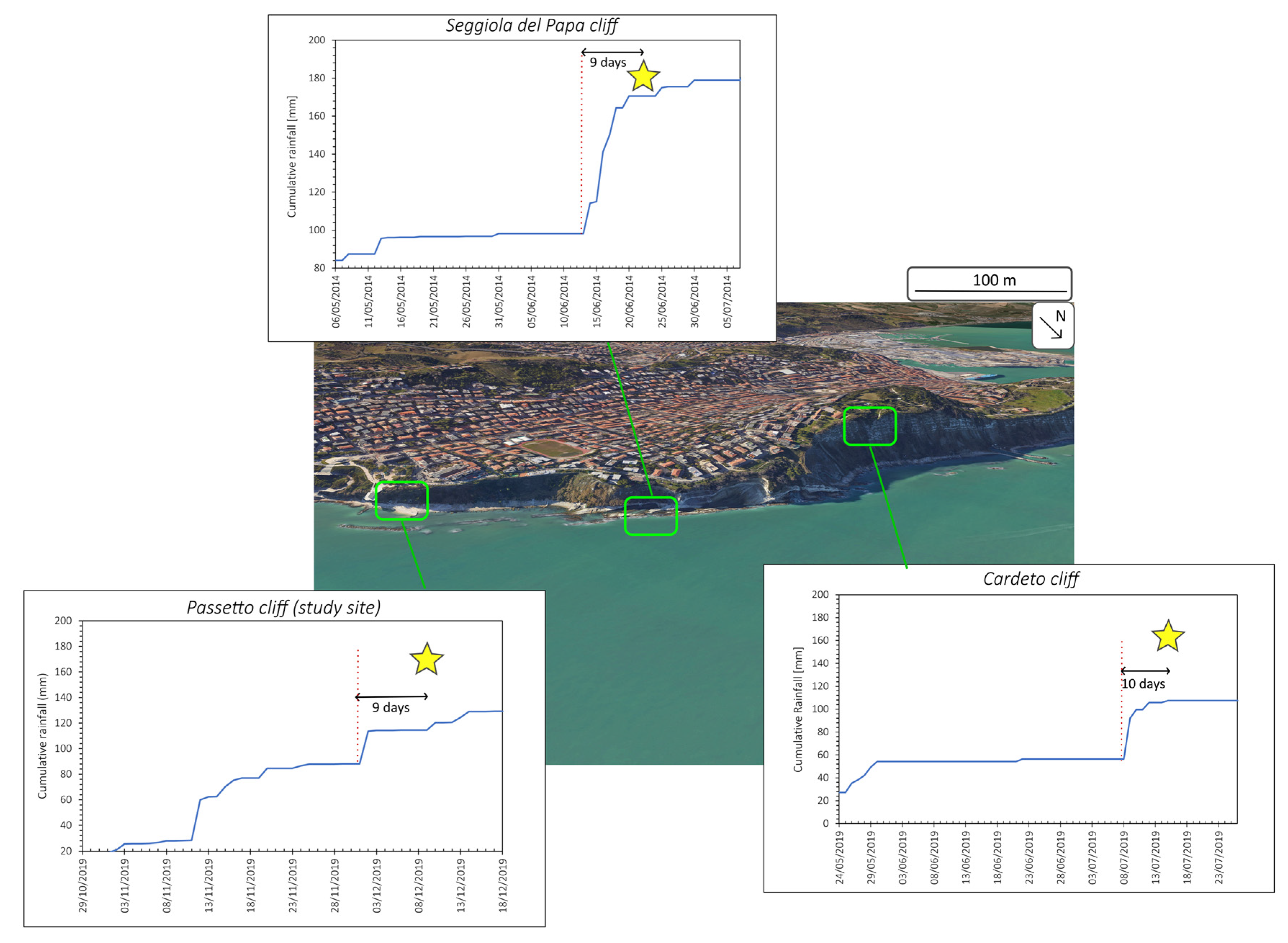
This simple but well-defined model matches perfectly with the time lag observed between the precipitation events and rockfall phenomena. Indeed, by analysing three rockfall events for which data are available to the authors [85,86] (Figure 11), a systematic delay of 9–10 days was observed between rainfall and rockfalls in the Schlier Fm. coastal cliff, characterised by different rock slope kinematics.

6. Conclusions

The approach used in this study, which combined remote sensing techniques (i.e., UAV-based photogrammetry) with traditional geomechanical analysis and tracer tests has been proved useful in determining the conductivity parameter of a fractured rock mass under unsaturated conditions. The unsaturated conditions are known to be much more complex to investigate, because a deep knowledge of the infiltration processes is required. For this reason, this approach can be satisfactory if used in the absence of boreholes or active conduits, obtaining information about the hydraulic conductivity characterising the recharge zone. The hydrological investigation performed using artificial tracer tests conveyed by a double ring infiltrometer became a novel and useful approach to depict important information on the fracture conductivity. However, the method put to light the general match between recharge mechanisms, water circulation within fractures, and cliff collapse, which are driven by the high connectivity of fracture sets. The evidence of different tracer arrivals in the monitored fractures, coupled with connectivity value and DFN results, highlighted important links between water circulation in the fractures and rockfall triggering. More precisely, it was found that in the study area, the time laps between heavy rainfall and rockfalls were usually 9–10 days. The water infiltrated at the top of cliff tent to infiltrate J3 as the most kinematically dangerous joint set, prone to planar and wedge failures.
Thanks to the DFN analysis, it was also possible to define the potential block volumes failing along such joint systems, which range from 0.1 to 1 m3 in agreement with the block failures surveyed in the area. It became clear that the presented integrated approach, being able to offer the possibility of understanding the time laps between heavy rainfall and rockfalls, the failure mechanisms, and rock block volumes, can play a key role in improving the study of rockfall hazards and defining the potential mitigation measures to be adopted.

Author Contributions

Conceptualization, E.M., D.F. and M.F.; methodology, E.M., D.F. and M.F.; software, E.M., M.F., T.V. and A.P.; validation, E.M., M.F. and D.F.; formal analysis, E.M., D.F. and A.P.; investigation, E.M., D.F., A.P. and M.F.; data curation, E.M., D.F., A.P. and M.F.; writing—original draft preparation, E.M., D.F., A.P. and M.F.; writing—review and editing, E.M., D.F, T.V., A.T., S.M. and M.F.; visualization, E.M, D.F. and A.P.; supervision, M.F., A.T., E.M. and D.F.; project administration, A.T. and M.F.; funding acquisition, A.T. All authors have read and agreed to the published version of the manuscript.

Funding

This research received no external funding.

Data Availability Statement

Not applicable.

Acknowledgments

The authors kindly regard Lorenzo D’Antonio for supporting the field survey operations and the Ancona Town Municipality for providing permissions to perform field tests. The authors thank the editors and the anonymous reviewers. Figures are made with the freely available Inkscape software v.1.1.2 (https://inkscape.org/release/inkscape-1.1.2/, accessed on 1 July 2022).

Conflicts of Interest

The authors declare no conflict of interest.

References

  1. Karra, S.; O’Malley, D.; Hyman, J.D.; Viswanathan, H.S.; Srinivasan, G. Modeling Flow and Transport in Fracture Networks Using Graphs. Phys. Rev. E 2018, 97, 033304. [Google Scholar] [CrossRef] [PubMed] [Green Version]
  2. Berkowitz, B. Characterizing Flow and Transport in Fractured Geological Media: A Review. Adv. Water Resour. 2002, 25, 861–884. [Google Scholar] [CrossRef]
  3. Adler, P.M.; Thovert, J.-F.; Mourzenko, V.V. Fractured Porous Media; Oxford University Press: Oxford, UK, 2013; ISBN 0-19-966651-2. [Google Scholar]
  4. Worthington, S.R. Estimating Effective Porosity in Bedrock Aquifers. Groundwater 2022, 60, 169–179. [Google Scholar] [CrossRef]
  5. Krzeminska, D.M.; Bogaard, T.A.; Van Asch, T.W.; Van Beek, L.P.H. A Conceptual Model of the Hydrological Influence of Fissures on Landslide Activity. Hydrol. Earth Syst. Sci. 2012, 16, 1561–1576. [Google Scholar] [CrossRef] [Green Version]
  6. Krzeminska, D.M.; Bogaard, T.A.; Malet, J.-P.; Van Beek, L.P.H. A Model of Hydrological and Mechanical Feedbacks of Preferential Fissure Flow in a Slow-Moving Landslide. Hydrol. Earth Syst. Sci. 2013, 17, 947–959. [Google Scholar] [CrossRef] [Green Version]
  7. Camanni, G.; Vinci, F.; Tavani, S.; Ferrandino, V.; Mazzoli, S.; Corradetti, A.; Parente, M.; Iannace, A. Fracture Density Variations within a Reservoir-Scale Normal Fault Zone: A Case Study from Shallow-Water Carbonates of Southern Italy. J. Struct. Geol. 2021, 151, 104432. [Google Scholar] [CrossRef]
  8. Mayolle, S.; Soliva, R.; Dominguez, S.; Wibberley, C.; Caniven, Y. Nonlinear Fault Damage Zone Scaling Revealed through Analog Modeling. Geology 2021, 49, 968–972. [Google Scholar] [CrossRef]
  9. Price, J. Implications of Groundwater Behaviour on the Geomechanics of Rock Slope Stability. In Proceedings of the APSSIM 2016: Proceedings of the First Asia Pacific Slope Stability in Mining Conference, Brisbane, WLS, Australia, 4–6 September 2016; pp. 25–48. [Google Scholar]
  10. Vasarhelyi, B.; Ván, P.J.E.G. Influence of water content on the strength of rock. Eng. Geol. 2006, 84, 70–74. [Google Scholar] [CrossRef]
  11. Althaus, E.; Friz-Töpfer, A.; Lempp, C.; Natau, O. Effects of Water on Strength and Failure Mode of Coarse-Grained Granites at 300 C. Rock Mech. Rock Eng. 1994, 27, 1–21. [Google Scholar] [CrossRef]
  12. Pan, Y.; Wu, G.; Zhao, Z.; He, L. Analysis of Rock Slope Stability under Rainfall Conditions Considering the Water-Induced Weakening of Rock. Comput. Geotech. 2020, 128, 103806. [Google Scholar] [CrossRef]
  13. Neuman, S.P. Trends, Prospects and Challenges in Quantifying Flow and Transport through Fractured Rocks. Hydrogeol. J. 2005, 13, 124–147. [Google Scholar] [CrossRef]
  14. Wei, M.; Dai, F.; Ji, Y.; Wu, W. Effect of Fluid Pressure Gradient on the Factor of Safety in Rock Stability Analysis. Eng. Geol. 2021, 294, 106346. [Google Scholar] [CrossRef]
  15. International Society for Rock Mechanics Commission on Standardization of Laboratory and Field Tests. Suggested Methods for the Quantitative Description of Discontinuities in Rock Masses. Int. J. Rock Mech. Min. Sci. Geomech. Abstr. 1978, 15, 319–368. [Google Scholar] [CrossRef]
  16. Volatili, T.; Agosta, F.; Cardozo, N.; Zambrano, M.; Lecomte, I.; Tondi, E. Outcrop-Scale Fracture Analysis and Seismic Modelling of a Basin-Bounding Normal Fault in Platform Carbonates, Central Italy. J. Struct. Geol. 2022, 155, 104515. [Google Scholar] [CrossRef]
  17. Jia, L.; Cai, J.; Wu, L.; Qin, T.; Song, K. Influence of Fracture Geometric Characteristics on Fractured Rock Slope Stability. Appl. Sci. 2023, 13, 236. [Google Scholar] [CrossRef]
  18. Daniela, R.; Ermanno, M.; Antonio, P.; Pasquale, R.; Marco, V. Assessment of Tuff Sea Cliff Stability Integrating Geological Surveys and Remote Sensing. Case History from Ventotene Island (Southern Italy). Remote Sens. 2020, 12, 2006. [Google Scholar] [CrossRef]
  19. Leucci, G.; Persico, R.; De Giorgi, L.; Lazzari, M.; Colica, E.; Martino, S.; Iannucci, R.; Galone, L.; D’Amico, S. Stability Assessment and Geomorphological Evolution of Sea Natural Arches by Geophysical Measurement: The Case Study of Wied Il-Mielah Window (Gozo, Malta). Sustainability 2021, 13, 12538. [Google Scholar] [CrossRef]
  20. Kemeny, J.; Post, R. Estimating Three-Dimensional Rock Discontinuity Orientation from Digital Images of Fracture Traces. Comput. Geosci. 2003, 29, 65–77. [Google Scholar] [CrossRef]
  21. Feng, Q.H.; Röshoff, K. In-Situ Mapping and Documentation of Rock Faces Using a Full-Coverage 3d Laser Scanning Technique. Int. J. Rock Mech. Min. Sci. 2004, 41, 139–144. [Google Scholar] [CrossRef]
  22. Pringle, J.K.; Westerman, R.; Gardiner, A.R. Virtual Geological Outcrops-Fieldwork and Analysis Made Less Exhaustive? Geol. Today 2004, 20, 64–69. [Google Scholar] [CrossRef]
  23. Mammoliti, E.; Stefano, F.D.; Fronzi, D.; Mancini, A.; Malinverni, E.S.; Tazioli, A. A Machine Learning Approach to Extract Rock Mass Discontinuity Orientation and Spacing, from Laser Scanner Point Clouds. Remote Sens. 2022, 14, 2365. [Google Scholar] [CrossRef]
  24. Gigli, G.; Casagli, N. Semi-Automatic Extraction of Rock Mass Structural Data from High Resolution LIDAR Point Clouds. Int. J. Rock Mech. Min. Sci. 2011, 48, 187–198. [Google Scholar] [CrossRef]
  25. Lato, M.; Diederichs, M.S.; Hutchinson, D.J.; Harrap, R. Optimization of LiDAR Scanning and Processing for Automated Structural Evaluation of Discontinuities in Rockmasses. Int. J. Rock Mech. Min. Sci. 2009, 46, 194–199. [Google Scholar] [CrossRef]
  26. Gigli, G.; Morelli, S.; Fornera, S.; Casagli, N. Terrestrial Laser Scanner and Geomechanical Surveys for the Rapid Evaluation of Rock Fall Susceptibility Scenarios. Landslides 2014, 11, 1–14. [Google Scholar] [CrossRef] [Green Version]
  27. Riquelme, A.J.; Abellán, A.; Tomás, R. Discontinuity Spacing Analysis in Rock Masses Using 3D Point Clouds. Eng. Geol. 2015, 195, 185–195. [Google Scholar] [CrossRef] [Green Version]
  28. Gigli, G.; Frodella, W.; Garfagnoli, F.; Morelli, S.; Mugnai, F.; Menna, F.; Casagli, N. 3-D Geomechanical Rock Mass Characterization for the Evaluation of Rockslide Susceptibility Scenarios. Landslides 2014, 11, 131–140. [Google Scholar] [CrossRef]
  29. Nyberg, B.; Nixon, C.W.; Sanderson, D.J. NetworkGT: A GIS Tool for Geometric and Topological Analysis of Two-Dimensional Fracture Networks. Geosphere 2018, 14, 1618–1634. [Google Scholar] [CrossRef] [Green Version]
  30. Laux, D.; Henk, A. Terrestrial Laser Scanning and Fracture Network Characterisation–Perspectives for a (Semi-) Automatic Analysis of Point Cloud Data from Outcrops. Z. Dtsch. Ges. Für Geowiss. 2015, 166, 99–118. [Google Scholar] [CrossRef]
  31. Massaro, L.; Corradetti, A.; Vinci, F.; Tavani, S.; Iannace, A.; Parente, M.; Mazzoli, S. Multiscale Fracture Analysis in a Reservoir-Scale Carbonate Platform Exposure (Sorrento Peninsula, Italy): Implications for Fluid Flow. Geofluids 2018, 2018, 7526425. [Google Scholar] [CrossRef] [Green Version]
  32. Loiotine, L.; Liso, I.S.; Parise, M.; Andriani, G.F. Optimization of Geostructural Surveys in Rock Mass Stability Analyses Using Remote Sensing Techniques. Ital. J. Eng. Geol. Environ. 2019, 73–78. [Google Scholar] [CrossRef]
  33. Walter, C.; Faraj, F.; Fotopoulos, G.; Braun, A. Augmenting Geological Field Mapping with Real-Time, 3-D Digital Outcrop Scanning and Modeling. Geosphere 2022, 18, 762–779. [Google Scholar] [CrossRef]
  34. Sturzenegger, M.; Stead, D. Close-Range Terrestrial Digital Photogrammetry and Terrestrial Laser Scanning for Discontinuity Characterization on Rock Cuts. Eng. Geol. 2009, 106, 163–182. [Google Scholar] [CrossRef]
  35. Jablonska, D.; Pitts, A.; Di Celma, C.; Volatili, T.; Alsop, G.I.; Tondi, E. 3D Outcrop Modelling of Large Discordant Breccia Bodies in Basinal Carbonates of the Apulian Margin, Italy. Mar. Pet. Geol. 2021, 123, 104732. [Google Scholar] [CrossRef]
  36. Schilirò, L.; Robiati, C.; Smeraglia, L.; Vinci, F.; Iannace, A.; Parente, M.; Tavani, S. An Integrated Approach for the Reconstruction of Rockfall Scenarios from UAV and Satellite-Based Data in the Sorrento Peninsula (Southern Italy). Eng. Geol. 2022, 308, 106795. [Google Scholar] [CrossRef]
  37. Pitts, A.D.; Casciano, C.I.; Patacci, M.; Longhitano, S.G.; Di Celma, C.; McCaffrey, W.D. Integrating Traditional Field Methods with Emerging Digital Techniques for Enhanced Outcrop Analysis of Deep Water Channel-Fill Deposits. Mar. Pet. Geol. 2017, 87, 2–13. [Google Scholar] [CrossRef] [Green Version]
  38. Smeraglia, L.; Mercuri, M.; Tavani, S.; Pignalosa, A.; Kettermann, M.; Billi, A.; Carminati, E. 3D Discrete Fracture Network (DFN) Models of Damage Zone Fluid Corridors within a Reservoir-Scale Normal Fault in Carbonates: Multiscale Approach Using Field Data and UAV Imagery. Mar. Pet. Geol. 2021, 126, 104902. [Google Scholar] [CrossRef]
  39. Giuffrida, A.; La Bruna, V.; Castelluccio, P.; Panza, E.; Rustichelli, A.; Tondi, E.; Giorgioni, M.; Agosta, F. Fracture Simulation Parameters of Fractured Reservoirs: Analogy with Outcropping Carbonates of the Inner Apulian Platform, Southern Italy. J. Struct. Geol. 2019, 123, 18–41. [Google Scholar] [CrossRef]
  40. Seers, T.D.; Sheharyar, A.; Tavani, S.; Corradetti, A. Virtual Outcrop Geology Comes of Age: The Application of Consumer-Grade Virtual Reality Hardware and Software to Digital Outcrop Data Analysis. Comput. Geosci. 2022, 159, 105006. [Google Scholar] [CrossRef]
  41. Corradetti, A.; Tavani, S.; Parente, M.; Iannace, A.; Vinci, F.; Pirmez, C.; Torrieri, S.; Giorgioni, M.; Pignalosa, A.; Mazzoli, S. Distribution and Arrest of Vertical Through-Going Joints in a Seismic-Scale Carbonate Platform Exposure (Sorrento Peninsula, Italy): Insights from Integrating Field Survey and Digital Outcrop Model. J. Struct. Geol. 2018, 108, 121–136. [Google Scholar] [CrossRef]
  42. Lei, Q.; Latham, J.-P.; Tsang, C.-F. The Use of Discrete Fracture Networks for Modelling Coupled Geomechanical and Hydrological Behaviour of Fractured Rocks. Comput. Geotech. 2017, 85, 151–176. [Google Scholar] [CrossRef]
  43. Makedonska, N.; Jafarov, E.; Doe, T.; Schwering, P.; Neupane, G. EGS Collab Team Simulation of Injected Flow Pathways in Geothermal Fractured Reservoir Using Discrete Fracture Network Model. In Proceedings of the 45th Workshop on Geothermal Reservoir Engineering, Stanford, CA, USA, 10–12 February 2020; pp. 10–12. [Google Scholar]
  44. Zhang, Q.-H.; Yin, J.-M. Solution of Two Key Issues in Arbitrary Three-Dimensional Discrete Fracture Network Flow Models. J. Hydrol. 2014, 514, 281–296. [Google Scholar] [CrossRef]
  45. Volatili, T.; Zambrano, M.; Cilona, A.; Huisman, B.A.H.; Rustichelli, A.; Giorgioni, M.; Vittori, S.; Tondi, E. From Fracture Analysis to Flow Simulations in Fractured Carbonates: The Case Study of the Roman Valley Quarry (Majella Mountain, Italy). Mar. Pet. Geol. 2019, 100, 95–110. [Google Scholar] [CrossRef]
  46. Romano, V.; Bigi, S.; Carnevale, F.; Hyman, J.D.; Karra, S.; Valocchi, A.J.; Tartarello, M.C.; Battaglia, M. Hydraulic Characterization of a Fault Zone from Fracture Distribution. J. Struct. Geol. 2020, 135, 104036. [Google Scholar] [CrossRef]
  47. Panza, E.; Sessa, E.; Agosta, F.; Giorgioni, M. Discrete Fracture Network Modelling of a Hydrocarbon-Bearing, Oblique-Slip Fault Zone: Inferences on Fault-Controlled Fluid Storage and Migration Properties of Carbonate Fault Damage Zones. Mar. Pet. Geol. 2018, 89, 263–279. [Google Scholar] [CrossRef]
  48. Giuffrida, A.; Agosta, F.; Rustichelli, A.; Panza, E.; La Bruna, V.; Eriksson, M.; Torrieri, S.; Giorgioni, M. Fracture Stratigraphy and DFN Modelling of Tight Carbonates, the Case Study of the Lower Cretaceous Carbonates Exposed at the Monte Alpi (Basilicata, Italy). Mar. Pet. Geol. 2020, 112, 104045. [Google Scholar] [CrossRef]
  49. Li, X.; Liu, J.; Gong, W.; Xu, Y.; Bowa, V.M. A Discrete Fracture Network Based Modeling Scheme for Analyzing the Stability of Highly Fractured Rock Slope. Comput. Geotech. 2022, 141, 104558. [Google Scholar] [CrossRef]
  50. Hamm, S.-Y.; Kim, M.; Cheong, J.-Y.; Kim, J.-Y.; Son, M.; Kim, T.-W. Relationship between Hydraulic Conductivity and Fracture Properties Estimated from Packer Tests and Borehole Data in a Fractured Granite. Eng. Geol. 2007, 92, 73–87. [Google Scholar] [CrossRef]
  51. Chen, G.; Illman, W.A.; Thompson, D.L.; Vesselinov, V.V.; Neuman, S.P. Geostatistical, Type-Curve, and Inverse Analyses of Pneumatic Injection Tests in Unsaturated Fractured Tuffs at the Apache Leap Research Site near Superior, Arizona. In Dynamics of Fluids in Fractured Rock; Blackwell Publishing Ltd.: Ofxord, UK, 2000; pp. 73–98. [Google Scholar]
  52. Fronzi, D.; Mirabella, F.; Cardellini, C.; Caliro, S.; Palpacelli, S.; Cambi, C.; Valigi, D.; Tazioli, A. The Role of Faults in Groundwater Circulation before and after Seismic Events: Insights from Tracers, Water Isotopes and Geochemistry. Water 2021, 13, 1499. [Google Scholar] [CrossRef]
  53. Fronzi, D.; Di Curzio, D.; Rusi, S.; Valigi, D.; Tazioli, A. Comparison between Periodic Tracer Tests and Time-Series Analysis to Assess Mid- and Long-Term Recharge Model Changes Due to Multiple Strong Seismic Events in Carbonate Aquifers. Water 2020, 12, 3073. [Google Scholar] [CrossRef]
  54. Mammoliti, E.; Fronzi, D.; Cambi, C.; Mirabella, F.; Cardellini, C.; Patacchiola, E.; Tazioli, A.; Caliro, S.; Valigi, D. A Holistic Approach to Study Groundwater-Surface Water Modifications Induced by Strong Earthquakes: The Case of Campiano Catchment (Central Italy). Hydrology 2022, 9, 97. [Google Scholar] [CrossRef]
  55. Iadanza, C.; Trigila, A.; Vittori, E.; Serva, L. Landslides in Coastal Areas of Italy. Geol. Soc. Lond. Spec. Publ. 2009, 322, 121–141. [Google Scholar] [CrossRef]
  56. Fruzzetti, V.M.E.; Segato, D.; Ruggeri, P.; Vita, A.; Sakellariadi, E.; Scarpelli, G. Fenomeni di Instabilità Della Falesia del Monte Conero: Ruolo Dell’assetto Strutturale. In Proceedings of the Incontro Annuale dei Ricercatori di Geotecnica 2011—IARG 2011, Torino, Italy, 4–6 July 2011; pp. 1–6. [Google Scholar]
  57. Pierantoni, P.; Deiana, G.; Galdenzi, S. Stratigraphic and Structural Features of the Sibillini Mountains (Umbria-Marche Apennines, Italy). Ital. J. Geosci. 2013, 132, 497–520. [Google Scholar] [CrossRef]
  58. Casagli, N.; Garzonio, C.A.; Nanni, T. Geomechanical Characterization and Slope Instability of the Marly Sea Cliffs of Ancona, Italy. In Proceedings of the Geotechnical Engineering of Hard Soils-Soft Rocks, Athens, Greece, 20–23 September 1993; pp. 1093–1100. [Google Scholar]
  59. Fronzi, D.; Gaiolini, M.; Mammoliti, E.; Colombani, N.; Palpacelli, S.; Marcellini, M.; Tazioli, A. Groundwater-Surface Water Interaction Revealed by Meteorological Trends and Groundwater Fluctuations on Stream Water Level. Acque Sotter. Ital. J. Groundw. 2022, 11, 19–28. [Google Scholar] [CrossRef]
  60. Barton, N.; Choubey, V. The Shear Strength of Rock Joints in Theory and Practice. Rock Mech. 1977, 10, 1–54. [Google Scholar] [CrossRef]
  61. Ortega, O.J.; Marrett, R.A.; Laubach, S.E. A Scale-Independent Approach to Fracture Intensity and Average Spacing Measurement. AAPG Bull. 2006, 90, 193–208. [Google Scholar] [CrossRef]
  62. Terzaghi, R.D. Sources of Error in Joint Surveys. Geotechnique 1965, 15, 287–304. [Google Scholar] [CrossRef]
  63. Fisher, R.A. Dispersion on a Sphere. Proc. R. Soc. Lond. Ser. Math. Phys. Sci. 1953, 217, 295–305. [Google Scholar] [CrossRef]
  64. Rocscience. DIPS. 2018. Available online: http://www.rocscience.com (accessed on 11 May 2018).
  65. Dershowitz, W.S.; Herda, H.H. Interpretation of Fracture Spacing and Intensity. In Proceedings of the 33rd US Symposium on Rock Mechanics (USRMS), Santa Fe, NM, USA, 8–10 June 1992. [Google Scholar]
  66. Sanderson, D.J.; Nixon, C.W. Topology, Connectivity and Percolation in Fracture Networks. J. Struct. Geol. 2018, 115, 167–177. [Google Scholar] [CrossRef]
  67. Petroleum Experts. Move. 2019. Available online: https://www.petex.com/ (accessed on 2 August 2022).
  68. Wenli, Y.; Sharifzadeh, M.; Yang, Z.; Xu, G.; Fang, Z. Assessment of Fracture Characteristics Controlling Fluid Flow Performance in Discrete Fracture Networks (DFN). J. Pet. Sci. Eng. 2019, 178, 1104–1111. [Google Scholar] [CrossRef]
  69. Cowie, P.A.; Scholz, C.H. Displacement-Length Scaling Relationship for Faults: Data Synthesis and Discussion. J. Struct. Geol. 1992, 14, 1149–1156. [Google Scholar] [CrossRef]
  70. Olson, J.E. Sublinear Scaling of Fracture Aperture versus Length: An Exception or the Rule? J. Geophys. Res. Solid Earth 2003, 108, 35. [Google Scholar] [CrossRef]
  71. Scholz, C.H. A Note on the Scaling Relations for Opening Mode Fractures in Rock. J. Struct. Geol. 2010, 32, 1485–1487. [Google Scholar] [CrossRef]
  72. Zambrano, M.; Pitts, A.D.; Salama, A.; Volatili, T.; Giorgioni, M.; Tondi, E. Analysis of Fracture Roughness Control on Permeability Using SfM and Fluid Flow Simulations: Implications for Carbonate Reservoir Characterization. Geofluids 2019, 2019, 4132386. [Google Scholar] [CrossRef] [Green Version]
  73. Chua, L.H.; Robertson, A.P.; Yee, W.K.; Shuy, E.B.; Lo, E.Y.; Lim, T.T.; Tan, S.K. Use of Fluorescein as a Ground Water Tracer in Brackish Water Aquifers. Groundwater 2007, 45, 85–88. [Google Scholar] [CrossRef]
  74. Sabatini, D.A.; Austin, T.A. Characteristics of Rhodamine WT and Fluorescein as Adsorbing Ground-water Tracers. Groundwater 1991, 29, 341–349. [Google Scholar] [CrossRef]
  75. Kasnavia, T.; Vu, D.; Sabatini, D.A. Fluorescent Dye and Media Properties Affecting Sorption and Tracer Selection. Groundwater 1999, 37, 376–381. [Google Scholar] [CrossRef]
  76. Sutton, D.J.; Kabala, Z.J.; Francisco, A.; Vasudevan, D. Limitations and Potential of Commercially Available Rhodamine WT as a Groundwater Tracer. Water Resour. Res. 2001, 37, 1641–1656. [Google Scholar] [CrossRef]
  77. Corbett, D.R.; Dillon, K.; Burnett, W. Tracing Groundwater Flow on a Barrier Island in the North-East Gulf of Mexico. Estuar. Coast. Shelf Sci. 2000, 51, 227–242. [Google Scholar] [CrossRef] [Green Version]
  78. Field, M.S.; Wilhelm, R.G.; Quinlan, J.F.; Aley, T.J. An Assessment of the Potential Adverse Properties of Fluorescent Tracer Dyes Used for Groundwater Tracing. Environ. Monit. Assess. 1995, 38, 75–96. [Google Scholar] [CrossRef]
  79. James, M.R.; Chandler, J.H.; Eltner, A.; Fraser, C.; Miller, P.E.; Mills, J.P.; Noble, T.; Robson, S.; Lane, S.N. Guidelines on the Use of Structure-from-motion Photogrammetry in Geomorphic Research. Earth Surf. Process. Landf. 2019, 44, 2081–2084. [Google Scholar] [CrossRef]
  80. Philip, J.R. The Theory of Infiltration: 4. Sorptivity and Algebraic Infiltration Equations. Soil Sci. 1957, 84, 257–264. [Google Scholar] [CrossRef]
  81. He, L.; Coggan, J.; Francioni, M.; Eyre, M. Maximizing Impacts of Remote Sensing Surveys in Slope Stability—A Novel Method to Incorporate Discontinuities into Machine Learning Landslide Prediction. ISPRS Int. J. GeoInf. 2021, 10, 232. [Google Scholar] [CrossRef]
  82. Devoto, S.; Macovaz, V.; Mantovani, M.; Soldati, M.; Furlani, S. Advantages of Using UAV Digital Photogrammetry in the Study of Slow-Moving Coastal Landslides. Remote Sens. 2020, 12, 3566. [Google Scholar] [CrossRef]
  83. Francioni, M.; Antonaci, F.; Sciarra, N.; Robiati, C.; Coggan, J.; Stead, D.; Calamita, F. Application of Unmanned Aerial Vehicle Data and Discrete Fracture Network Models for Improved Rockfall Simulations. Remote Sens. 2020, 12, 2053. [Google Scholar] [CrossRef]
  84. Tuckey, Z. An Integrated UAV Photogrammetry-Discrete Element Investigation of Jointed Triassic Sandstone near Sydney, Australia. Eng. Geol. 2022, 297, 106517. [Google Scholar] [CrossRef]
  85. Berardinelli, D. Crollo al Passetto, Daniele Berardinelli (PdL): “Anni Di Promesse Ma Nessun Intervento”. 2014. Available online: https://www.anconatoday.it/politica/frana-passetto-ancona-daniele-berardinelli-forza-italia.html (accessed on 1 July 2022).
  86. Verdenelli, M. Ancona, Crolli Alla Spiaggia Della Grotta Azzurra. 2019. Available online: https://www.ilrestodelcarlino.it/ancona/cronaca/crolli-grotta-azzurra-1.4694097 (accessed on 1 July 2022).
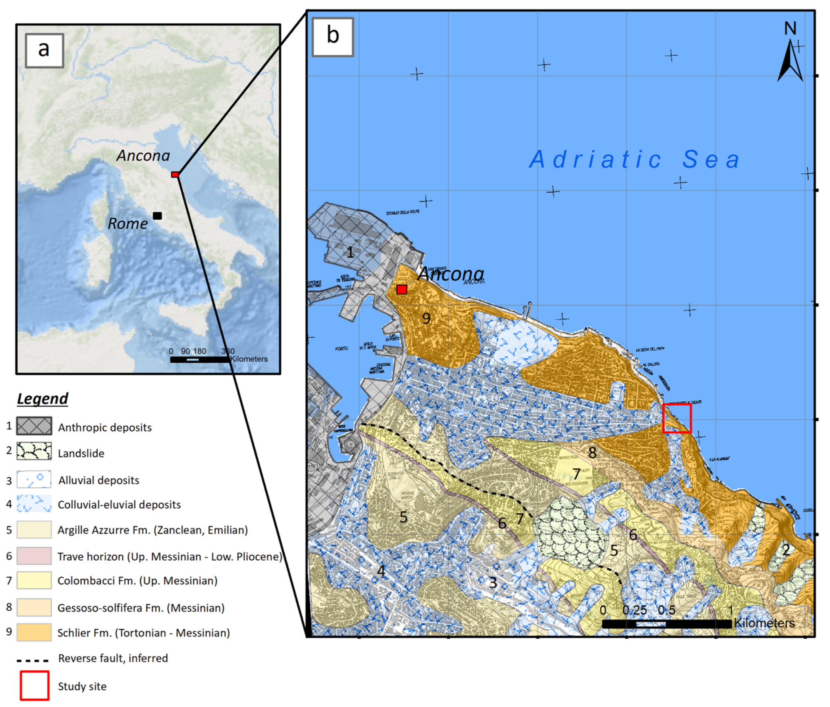
Figure 1. Geographical (a) and geological framework of the study area, with indication of the study site (b).
Remotesensing 15 01222 g001
Figure 2. Overview of the monitoring strategy. (a) Position of the tracer injection point and the UAV survey; (b) UAV survey area; (c) position of the scanlines for the conventional geomechanical survey, with indication of the activated charcoal traps for tracer monitoring and some of the GCPs.
Remotesensing 15 01222 g002
Figure 3. (a) 2D pseudo-scanline creation (in green) in the initial Discrete Fracture Network model; (b) pseudo-scanlines extracted from the DFN and used to calculate P21.
Remotesensing 15 01222 g003
Figure 4. (a) 3D model with indication of the sampling windows used for the P21 determination and the DFN modelling; (b) stereonet with pole vector plot (lower hemisphere, equal angle) with indication of mean set dip angle and dip direction of the planes.
Remotesensing 15 01222 g004
Figure 5. Fracture analysis results performed in NetworkGT for fracture set J1, J2, and J3 of sampling window 1. (a) with orthophoto base map; (b) without orthophoto; (c) DFN model developed after the iterative approach; (d) pseudo-scanlines extracted from the DFN and imported in NetworkGT for the validation procedure.
Remotesensing 15 01222 g005
Figure 6. Topological analysis results for (a) sampling window 1 and (c) sampling window 2. The nodes of the fracture network are classified as isolated (I) nodes or connecting (Y or X) nodes. I-I = isolated-isolated, C-C = connected-connected. C-I = connected-isolated. Ternary plots are reported for sampling window 1 (b) and for sampling window 2 (d).
Remotesensing 15 01222 g006
Figure 7. Kinematic analysis of slope stability. (a) Planar sliding failure; (b) wedge sliding.
Remotesensing 15 01222 g007
Figure 8. (a) Cliff orientation (dip direction) extracted from the UAV model; (b) rock slope kinematics observed in the area, with the location of tracer release and raw illustration of fractures and groundwater flow.
Remotesensing 15 01222 g008
Figure 9. Tracer test results with details about detection points and location of tracer traps within discontinuities. The graph reports in the upper part the daily rainfall values in millimeters recorded from the day of injection (25 February 2022).
Remotesensing 15 01222 g009
Figure 10. (a) Water head above diver measured within the inner ring for the four consecutive recharge simulations, fitted by exponential curves with related Pearson’s determination coefficients (R2); (b) cumulative infiltration vs. time for the 4° recharge (the red markers show the measured data, the dashed line shows the model result of Philip [80].
Remotesensing 15 01222 g010
Figure 11. Relation between rockfall events in the coastal area of Ancona and cumulative rainfall. The location of three events recorded between 2014 and 2019 involving the Schlier Fm. near the analysed area (Passetto cliff) are reported.
Remotesensing 15 01222 g011
Table 1. Independent check measurements.
Total Station Measurement (m)3D Model (m)
64.47264.458
Compass measurement of dip and dip direction (degrees)3D model-extracted dip and dip direction (degrees)
65/6760/68
Table 2. Discontinuity set characteristics from the geomechanical survey. n.d. = not detected.
J1J2J3S0
Dip angle/Dip direction (°) 71/14188/18865/6746/231
Fisher value 25.91481867
Fracture trace length (m)Min0.20.20.18n.d.
Mean1.821.602.22n.d.
Max12.4611.3213.87n.d.
Std Dev2.062.142.86n.d.
Min0.180.120.18n.d.
Hydraulic aperture (mm)Mean0.240.190.25n.d.
Max0.950.50.5n.d.
Min0.900.700.90n.d.
Mechanical aperture (mm)Mean0.950.851.00n.d.
Max2.601.801.80n.d.
Table 3. Fracture intensity analysis from the sampling windows and DFN model. n.d. = not detected.
J1J2J3S0
Mean P21 (sampling window 1, m/m2)0.960.741.89n.d.
Mean P21 of the DFN (m/m2)0.910.871.90n.d.
Fracture intensity P32 (m2/m3)0.80.51.8n.d.
Table 4. Results of conductivity (K) derived from the DFN model and tracer tests for the topsoil and fractures.
Average K (cm/s)
DFNfractures2.91 × 10−3
Tracer testfractures2.89 × 10−3
topsoil1.8 × 10−2 *
Where * is the Ksat.
Disclaimer/Publisher’s Note: The statements, opinions and data contained in all publications are solely those of the individual author(s) and contributor(s) and not of MDPI and/or the editor(s). MDPI and/or the editor(s) disclaim responsibility for any injury to people or property resulting from any ideas, methods, instructions or products referred to in the content.