Article

Remote Sensing Monitoring of the Pietrafitta Earth Flows in Southern Italy: An Integrated Approach Based on Multi-Sensor Data

1
Department of Sciences and Technologies, University of Sannio, 82100 Benevento, Italy
2
NHAZCA s.r.l., Via V. Bachelet 12, 00185 Rome, Italy
3
Earth Sciences Department, Sapienza University of Rome, Piazzale Aldo Moro 5, 00185 Rome, Italy
4
ISPRA—Geological Survey of Italy, Via V. Brancati 48, 00144 Roma, Italy
*
Author to whom correspondence should be addressed.
Remote Sens. 2023, 15(4), 1138; https://doi.org/10.3390/rs15041138
Submission received: 22 December 2022 / Revised: 2 February 2023 / Accepted: 17 February 2023 / Published: 19 February 2023

Abstract

:
Earth flows are complex gravitational events characterised by a heterogeneous displacement pattern in terms of scale, style, and orientation. As a result, their monitoring, for both knowledge and emergency purposes, represents a relevant challenge in the field of engineering geology. This paper aims to assess the capabilities, peculiarities, and limitations of different remote sensing monitoring techniques through their application to the Pietrafitta earth flow (Southern Italy). The research compared and combined data collected during the main landslide reactivations by different ground-based remote sensors such as Robotic Total Station (R-TS), Terrestrial Synthetic Aperture Radar Interferometry (T-InSAR), and Terrestrial Laser Scanner (TLS), with data being derived by satellite-based Digital Image Correlation (DIC) analysis. The comparison between R-TS and T-InSAR measurements showed that, despite their different spatial and temporal resolutions, the observed deformation trends remain approximately coherent. On the other hand, DIC analysis was able to detect a kinematic process, such as the expansion of the landslide channel, which was not detected by the other techniques used. The results suggest that, when faced with complex events, the use of a single monitoring technique may not be enough to fully observe and understand the processes taking place. Therefore, the limitations of each different technique alone can be solved by a multi-sensor monitoring approach.

1. Introduction

Earth flows can be dominant mass movements in hilly areas characterised by lithologically and structurally complex sequences [1,2]. Bulging toes, teardrop-shaped forms and smooth surface profiles are the most common features which identify this kind of intermittent landslide. In addition, the presences of discrete shear surfaces; viscous, finer grained material; and long periods of relative dormancy alternating with more rapid “surge” differ earth flows from other flow-like landslides [3].
Their activity is controlled by hydrologic forcing, the geometry of the basal slip surface, and the transmission of sediment pulses along the length of the flow.
These types of landslides are generally characterised by slow and persistent surface movements alternating between periods of rapid evolution, with the rates of displacement ranging between a few millimetres per day to more than one metre per day [4]. Accelerations or decelerations in surface displacement rates are mainly linked to the variation of the pore water pressure. However, the combination of prolonged rainfall, loss of efficient drainage pathways, and new sediment availability in the source area can cause earth flow surges. Under these conditions, the movement velocity can reach several metres per day. Moreover, during surge events, earth flow material can locally fluidise and fail catastrophically, involving life-line infrastructures (such as roadways and railways) and causing emergency phases in terms of civil protection [3,5,6,7,8,9].
The combination of slow (millimetres per day), long-term (over years) and localised (contained within five square meters or less) movements with surge events is a fundamental feature of earth flow activity [3]. Therefore, landslide monitoring, for knowledge, control or emergency purposes, requires the integration of different remote sensing and in situ techniques [10,11,12,13,14,15,16,17,18]. Where earth flows show the outcropping of shear surfaces, wire extensometers are one of the most common geotechnical tools used for continuous superficial displacement monitoring. This method is a cost-effective solution for slow and persistent movement, ensuring sub-millimetre accuracy [19,20,21]. However, wire extensometers allow one to detect only 1D deformation. In this case, the implementation of physical or optical benchmarks, for the use of Global Navigation Satellite System (GNSS) and Robotic Total Station (R-TS) technology, is necessary to measure earth flow movements. GNSS and R-TS enable the detection of 3D deformation with millimetric precision [10,19,22,23,24]. Although the potential high frequency of data collection (from seconds to hours) makes these methods suitable for near-real-time monitoring, the difficulty of installing distance targets on sloped surfaces during earth flow surges represents a great disadvantage. Terrestrial Synthetic Aperture Radar Interferometry (T-InSAR) allows one to overcome this drawback and, at the same time, ensures high temporal resolution and measurement accuracy (~10−3 m). Depending on the acquisition configuration, T-InSAR is able to detect several deformation rates, ranging from m/day to mm/day. These features make this technology an essential support as an early warning system in landslide risk management [25,26,27,28,29]. Nevertheless, T-InSAR is not particularly suited to investigating the 3D kinematics of earth flows due to its limitation of only measuring displacements along the Line of Sight (LOS). Instead, 3D models generated by Terrestrial Laser Scanner (TLS), Unmanned Aerial Vehicle (UAV) or Structure from Motion Photogrammetry (SfM-P) can detect deformation in all directions. Comparing between multi-temporal Point Clouds (PCs) or Digital Elevation Models (DEMs) (elaborated from PCs) allows us to reconstruct the topographic evolution and estimate the sediment and volumetric balance along the earth flows [22,30,31]. However, although SfM-P from TLS and UAV ensures high-density information covering large areas, it is unsuitable for near-real-time monitoring. Furthermore, the multi-temporal approach for earth flow monitoring (knowledge-control) can also be performed thanks to the application of Digital Image Correlation (DIC) algorithms for satellite images or TLS imagery analysis [32,33,34,35,36,37]. DIC algorithms can return displacement field maps with an accuracy that is a function of the spatial and temporal resolution of the dataset.
This paper presents the results of the integrated monitoring activity performed at the site of the Pietrafitta earth flow (southern Italy) during the surge event of April–May 2016 that affected the SS87 national road. The study exploits the displacement data recorded and derived from continuous T-InSAR and R-TS and multi-temporal TLS surveys during the landslide paroxysm. It also analyses the deformational processes through a DIC analysis of multispectral satellite imagery. Unfortunately, in then literature, only few works combined and critically evaluated different remote sensing techniques specifically focused on earth flows over the same time period. This represents a serious gap considering that such phenomena can generate damage to human settlements and assets. In this context, starting from this case study, following a bottom-up approach, the outcomes of various sensors and methodologies are thus integrated and compared to highlight advantages and limitations that are valuable for other earth flow sites.

2. Study Area and Landslide Features

The Pietrafitta earth flow (Lat = 41°13′12.83″N, Long = 14°44′32.51″E) affects the national road SS87 in Benevento Province (Campania Region, southern Italy), resulting in the occurrence of a typical slow-moving and intermittent event in the clay-rich flysch sequences of the Southern Apennines [1] (Figure 1A). It develops along the north-western slope of the Torre Palazzo hill on the southern side of the Reventa river valley from 200 to 250 m above sea level.
From a geological viewpoint, the Pietrafitta earth flow is located at an overthrust fault between (i) the Flysch Rosso formation (FYR) outcropping in the upper part of the slope, where the main scarp of the source area is located, and (ii) the Fragneto Monforte formation (UFM) at the middle and lower parts of the slope [38,39]. Lithological and structural complexity is the distinctive characteristic of these sequences, which consist of a chaotic alternation of clay, sandstone and calcareous marl levels.
The earth flow is placed across the main flow drainage axis of the slope. This position plays a key role in the movement direction and magnitude. The source area is complex and characterised by rotational–translational movements on the right side and by a flow-like zone on the left; downslope of the source area, the sliding of viscous–elastic materials is dominant above all when significant rainfalls occur. Soil softening and fluidification are favoured by local geomorphological and hydrogeological conditions [40] that lead superficial and shallow-circulating rainwater to be collected along the landslide axis.
The landslide was about 250 m long from the source area to the active bulging toe, covering an area of about 10 × 103 m2: its width ranged from ~30 m (middle channel) to ~100 m (source and depositional area). The landslide body had an average slope angle, including the head scarp, of about 16°, and involved an approximate volume of 3 × 105 × 10 m3. Landslide thickness ranged between 2 and 4–5 m.
The compound kinematic of the upper part of the source area, where grabens, scarps and back-tilted surfaces were present, together with the whole deformational pattern (normal, thrust and strike slip faults (Figure 1B)) have some similarities with those characterising other earth flows composed of multiple kinematic zones in similar geo-structural settings [41,42] and are related to the longitudinal geometry of the basal slip surface. In particular, a slip surface can be composed of an alternation between risers and treads controlled by the geologic complexity of the slope’s higher velocities occurring at steep traits (risers), with lower velocities occurring at gentle ones (treads).
Due to the landslide, since 2014, only one lane of the SS87 has allowed the passage of the motor vehicles, in an alternating manner; the other lane is occupied by part of the landslide toe. In October 2015, two intense and consecutive rainfall events affected Benevento Province, causing multiple effects such as floods, landslides and extensive soil erosion in a wide area [43,44]. The rainy events reactivated the landslide body, leading to the total closure of the road.

3. Materials and Methods

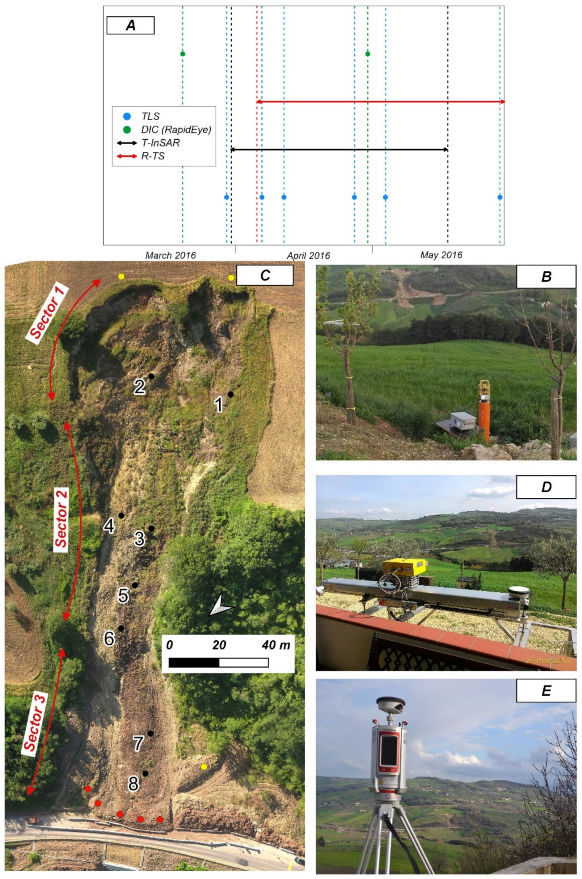
In order mitigate the risk of the deposit of landslide material on the transit lane, an integrated monitoring system of the earth flow displacement was installed in an emergency in March 2016 (Figure 2A). It consisted of (i) a Robotic Total Station (R-TS, Figure 2B), located on the opposite slope, looking at 16 reflectors (Figure 2C); (ii) a Terrestrial Synthetic Aperture Radar Interferometry (T-InSAR, Figure 2D) device, located in front of the landslide on the opposite slope; (iii) a Terrestrial Laser Scanner (TLS, Figure 2E) conducting multi-temporal scans; (iv) a video surveillance system, installed at the toe and working for 24 h; and (v) some experimental, low-cost sensors [20].
The joint use of different accurate monitoring techniques allowed safety countermeasures to be undertaken and alert procedures to be used in order to stop the traffic at the right time on the road. From July 2016, the landslide activity decreased, but by June, T-InSAR monitoring had been removed, and between November 2016 and July 2017, the TS monitoring was also temporarily stopped, in order to allow provisional works to be carried out.

3.1. Ground-Based Monitoring

3.1.1. Robotic Total Station (R-TS) Data

The R-TS represents the evolution of the common Total Station survey. It is equipped with a servomechanism and an automatic target recognition device, which locks onto a specific target and follows its movement [45]. This instrument allows the operator to work remotely, as it is able to move and orientate autonomously, and to measure the direction and magnitude of the displacement of a series of points with a maximum precision of up to a millimetre (depending on various factors such as type of instrumentation and the configuration of the monitoring network) at high sampling rates.
The measurements acquired during this study and presented here were recorded by a TOPCON 101 Robotic Total Station. The station was remote-controlled via 3G connection, and installed on the slope opposite the monitored slope, where 16 reflective prisms were installed at an average distance of 800 metres from the R-TS. For the analysis, we used the data recorded from 8 prisms (see Figure 2C for location) for the time span of 5 April 2016–31 May 2016, with an acquisition frequency of 1 h. Because of the continuous relocation, no completed time series were available for the remaining targets, and consequently, they were not considered for analysis. Moreover, it is worth noting that 3 optical prisms were installed in areas considered stable, and these were thus assumed as a reference. However, more than 1350 acquisitions were performed in less than 2 months.

3.1.2. Terrestrial Interferometric Synthetic Aperture Radar (T-InSAR) Data

T-InSAR is a ground-based radar which uses microwaves to remotely detect the displacement of natural targets through the measurement of the phase shift between two or more images collected at different times [26,27]. Radar signals are acquired by emitting and receiving antennas mounted in the radar head. This technology has several advantages, including (i) the ability to collect data with high temporal resolution (e.g., up to a few seconds) under any weather and lighting conditions, and (ii) the ability to remotely monitor an entire area, rather than single points. The main limitations are (i) that only the displacement component parallel to the Line of Sight (LOS) can be measured, and (ii) the risk of displacement underestimation for rapid processes due to the cyclical behaviour of the phase [26]. The main results which can be achieved by exploiting this technique involve the creation of both coloured maps and displacement time series from each pixel, when continuous monitoring is available.
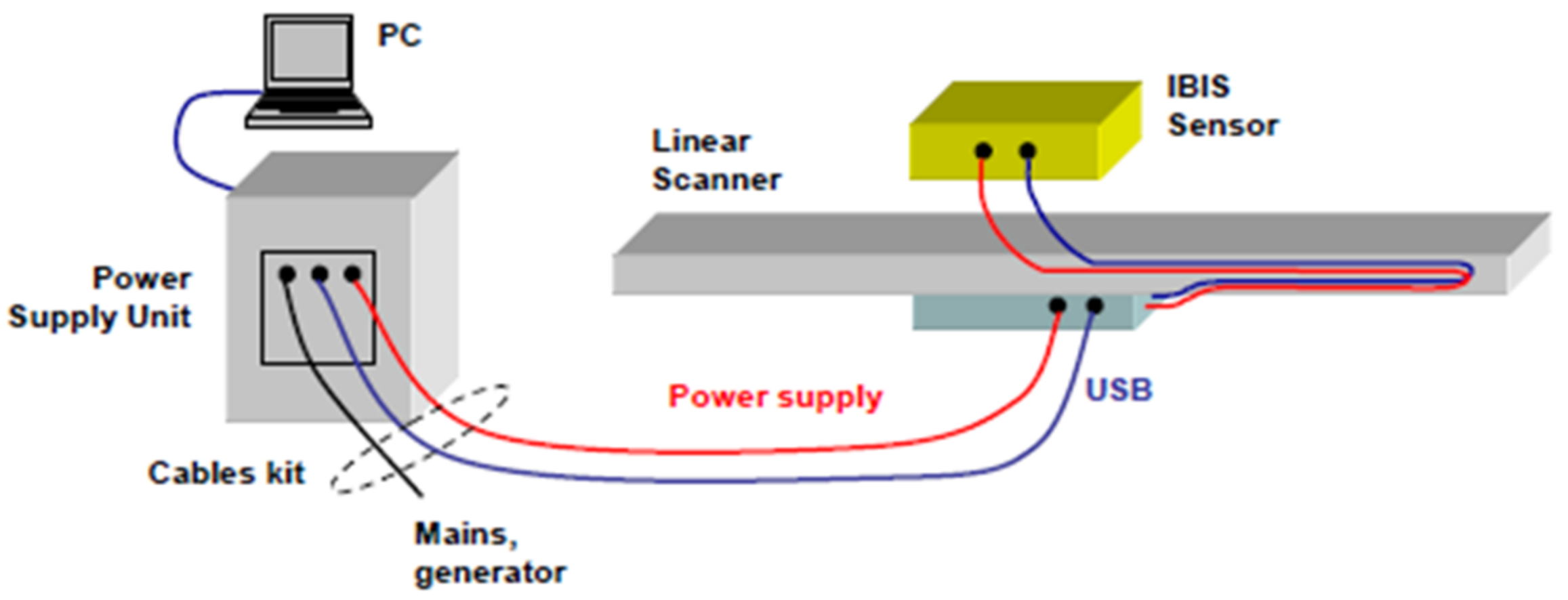
The equipment used in the present study is the IBIS-FL/FM radar device produced by IDS Georadar S.r.l. (Figure 2D). The SAR device consists of a sensor module, a linear track (2 metres), a control PC, a power supply and data processing software (Figure 3). The sensor module transmits an electromagnetic signal at a central frequency of 17.2 GHz (Ku band) with a maximum bandwidth of 200 MHz and an accuracy of up to 0.1 mm. The main characteristics of the sensor are shown in Table 1.
T-InSAR continuous monitoring started on 30 March 2016 and ended on 18 May 2016, with a temporal frequency of 5 min and more than 13,000 acquisitions recorded. Although the radar footprint covered an area larger than the extent of the landslide, the data analysis focused on Sector 3 of the landslide (see Figure 1B), which represented the most critical sector in terms of damages and risk to the road. Moreover, due to the presence of vegetation and shadow areas within the more distant sectors (1 and 2) causing continuous phase noise and a low correlation index, reliable displacement analyses in these areas could not be performed.
The analysis and monitoring were carried out using the IBIS Guardian software, a powerful tool for managing the SAR images acquired by the ground-based radar which enables the user to quickly interpret the information processed. The software is able to store long-term datasets within a single monitoring project. Furthermore, displacement data are provided to the user in real time by employing advanced automatic atmospheric correction techniques. The interpretation of radar data is made via the visualisation of fully georeferenced 3D data.

3.1.3. Terrestrial Laser Scanner (TLS) Data

TLS is an instrument based on laser technology capable of measuring the distance, with a high level of accuracy, between the instrument and the object being measured [16]. Thanks to mechanical systems and rotating and oscillating mirrors, it is able to direct laser pulses to different positions in space, thereby ‘scanning’ the objects in front of it. Among the suitable techniques for landslide monitoring, the TLS is one of the most generally applicable [46,47]. Moreover, it is characterised by lower instrumental accuracy compared to R-TS, but its surveys are very fast, efficient and precise.
The high-density Point Clouds provided (per cm2) can be processed to distinguish vegetation from soil [16]. The three-dimensional modelling of complex areas is also possible, combining surveys from different scanning positions [48].
The data used for this study were acquired by a Riegl Scan VZ-4000 Terrestrial Laser Scanner (TLS), positioned on the opposite slope at an average distance of approximately 800 metres (Figure 2E). The high-speed, high-resolution 3D Laser Scanner RIEGL VZ-4000 has a range of over 4000 m and a field of view of 60° vertically and 360° horizontally. It uses an invisible laser beam for eye-safe operation within Laser Class 1. The main characteristics of the sensor are shown in Table 2. Seven main scans were carried out from 29 March 2016 to 16 June 2016, as listed in Table 3.
The data obtained from the TLS scanning were used for the 3D modelling of the unstable slope surface and for the assessment of the volumetric differences related to the earth flow process by comparing several Point Clouds [49]. The analysis was carried out using the M3C2 plugin [50], which represents one of the main algorithms capable of producing distances directly between two Point Clouds implemented on Cloud Compare. Prior to the analysis using the M3C2 comparison algorithm, the Point Clouds were filtered by the presence of vegetation and aligned semi-automatically using the alignment tool on Cloud Compare (RMS error: 0.17).

3.2. Satellite PhotoMonitoring Data and Analysis

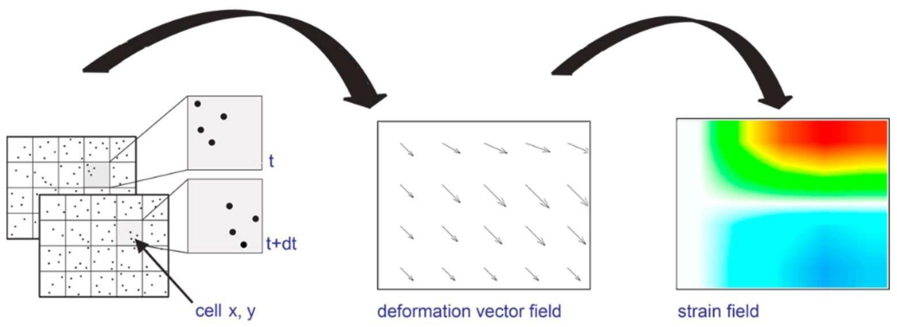
PhotoMonitoring is a new monitoring solution based on advanced digital image-processing algorithms that exploits the widespread use of optical/multispectral, hyperspectral and radar sensors worldwide to obtain information on changes or displacements in the terrain [51]. Analyses can be carried out on datasets of images acquired from the same type of platform, over the same area of interest and at different times, evaluating any variations in radiometric characteristics (Change Detection) and/or displacements occurring in the time interval covered by the image acquisition. Generally, the Digital Image Correlation (DIC) technique, which is an optical–numerical measurement technique, can provide full-field 2D and 3D displacements of any type of object surface (Figure 4) [32].
Recently, analyses based on DIC algorithms have been recognised as a powerful tool not only for measuring landslide displacements [52,53,54], but also for other monitoring applications, such as assessing the stability of flanks of active volcanos [55], tracking the flow of a glacier [56] or assessing earthquake-induced displacement [57]. DIC displacement measurements can theoretically provide a sub-pixel accuracy of approximately 1/50th of a pixel [58] under optimal conditions, although problems linked to image orientation, co-registration, topographical distortion, instrumental and atmospheric noise, temporal and spatial decorrelations and co-registration errors represent limitations that do not always allow these accuracy values to be achieved [59]. Algorithms available to date allow analysis between two images as well as between several consecutive images (multi-master analysis).

IRIS Software Analysis

Satellite PhotoMonitoring analysis was performed using IRIS software, developed by NHAZCA S.r.l., a start-up of the ‘Sapienza’ University of Rome, which enables Change Detection (CD) and Digital Image Correlation (DIC), using various algorithms from the relevant literature and new algorithms developed specifically for this purpose. The Change Detection method implemented in the software makes use of the Structural Similarity Index, an algorithm in which the measurement of image quality is based on an initial image taken as a reference. The method is used on a local scale, iteratively assessing image similarity over a small subset of image pixels using a sliding window approach, which allows the automatic identification of portions of the scene where changes have occurred. The displacement analysis method implemented uses different types of algorithms that exploit different analysis techniques (feature tracking, template matching, phase correlation algorithm). Displacement maps can be created through a single pair of images (single analysis approach) or through a stack of images depicting the same area (multi-master approach), which also permits the extrapolation of displacement time series for areas or pixels.
The analyses shown in this paper are based on high-resolution RapidEye satellite images, a constellation of five identical satellites owned and operated by Planet, launched on 29 August, 2008 (https://earth.esa.int/eogateway/catalog/rapideye-full-archive (accessed on 20 September 2022)). The sensors on the satellite platforms of this constellation produce images in five spectral bands (red, green, blue, red edge and near infrared), with a geometric resolution of 5 metres/pixel on orthorectified products.
A synopsis of the dataset used is shown in Table 4, which provides a description of the characteristics and dates of image collection.
In this case, the analysis was performed using the phase correlation algorithm [60], which is based on a frequency domain representation of the data, usually calculated by means of fast Fourier transforms (FT), with a moving variable window that, in this case, was 8 pixels. This algorithm, the most commonly used, is based on the FT translation property, which states that a shift of two relevant images in the spatial domain is transformed in the frequency domain as phase differences. In the following equation, the functions F u , v and G u , v are the corresponding FT of f x , y and g x , y , which we assume are two image functions, and F−1 denotes the inverse FT.
P C = F 1   F u , v G u , v F u , v G u , v =   F 1 e x p i u Δ x + v Δ y                            
The images, after being downloaded, were imported in the IRIS processing software. After the co-registration step, a landslide Region of Interest (ROI) was selected, and the analysis was started.

4. Results

4.1. R-TS Analysis

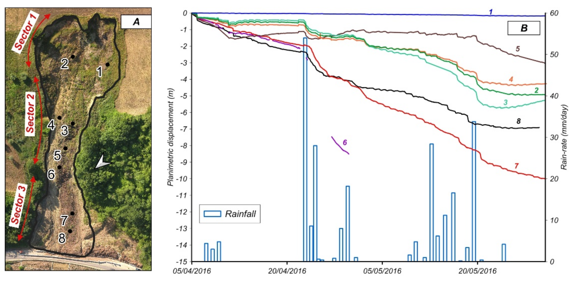
Figure 5 shows the cumulative planimetric displacements of the benchmarks selected for the analysis at each sector during the observation period.
Despite having different magnitudes, a common displacement trend was found for all benchmarks. The only exception is represented by benchmark 1, which is located on the left side of the source area, close to the landslide boundary. This difference could be due to the different kinematic behaviours of this area, where rotational sliding (i.e., retrogressive movements) is generally prevalent, unlike in the translational areas.
The maximum displacements recorded between 5 April 2016 and 31 May 2016 were ~4.5 m in Sector 2 and ~10 m in Sector 3, albeit with variable velocities. Significant accelerations were recorded after rainfall events. Figure 6B compares the cumulative displacement of the monitoring points, with rainfall data collected at the “San Lupo” rain gauge, managed by the Agrometeorological Center (Centro Agrometeorologico Regionale, C.A.R.) of the Campania Region, and located 9 km west at an elevation of 343 m a.s.l. The main accelerations occurred following the main rainy events of 23–25 April 2016 (85.6 mm) and 14–20 May 2016 (96.2 mm). Table 5 summarises the variation in the average displacement rate measured in a 5-day range from 23 April 2016 for each benchmark (except for benchmarks No. 1 and No. 5, as explained below), which contains continuous recordings for the whole period.
However, it should be noted that the irregular surface deformations caused the tilting of some optical prisms, affecting the measurements and resulting in a temporary rising-like trend of the time series. This is evident from the curve’s tail at benchmark 3 and parts of the benchmark 5 curve before and after the 23–25 April rainfall event. Because of the high displacement rate, benchmark 6 was not visible for several days and, subsequently, was completely lost.

4.2. T-InSAR Analysis

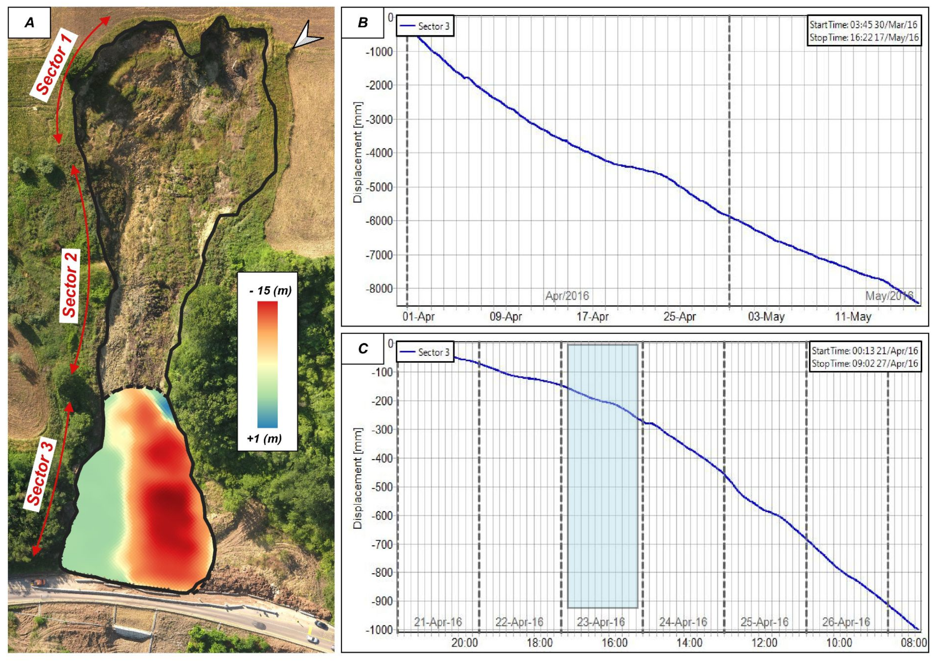
As shown in Figure 6A, the LOS cumulative displacement map obtained from the interferometric device highlights displacements of up to a maximum of 15 m on the left side of Sector 3 between 30 March 2016 and 18 May 2016. However, the average displacement of the entire Sector 3 was approximately 10 m. This value was computed from the average of the cumulative displacement recorded on each pixel of the map. The displacements mainly occurred along shear surfaces which border this area. No significant activity was identified at the left side of the toe and outside the landslide perimeter. The average displacement time series (Figure 6B) of the whole sector indicates a constant progression of the landslide toe, with sudden accelerations in connection with rainfall events (e.g., 23 April rainfall event (Figure 6C)). The average displacement rate recorded was ~0.1 m/day, whereas the maximum velocity was ~0.2 m/day on 25 April 2016.

4.3. TLS Analysis

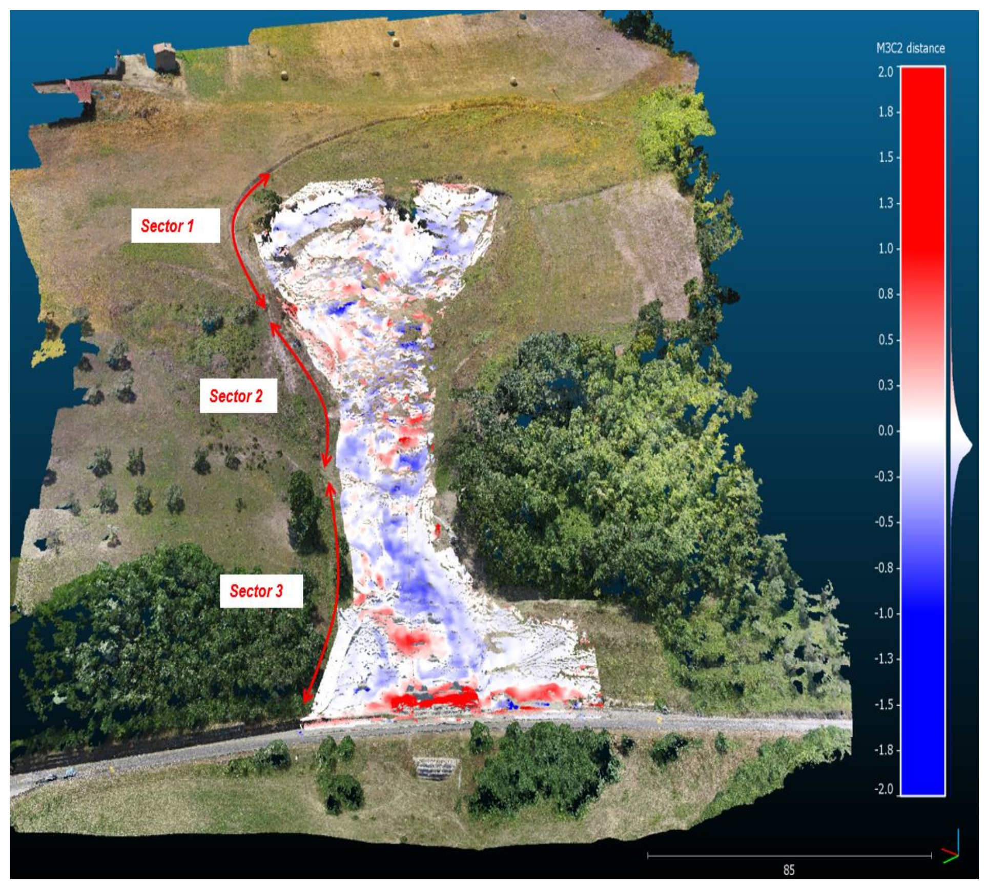
Figure 7 shows the results of TLS scans (29 March 2016–27 April 2016) performed at the site of the Pietrafitta earth flow. Considering that the vertical lowering and raising of the topographic surface are interpreted as the loss or gain and material, respectively, the colour map of Figure 7 indicates a prevalent loss of material along the left flank of the landslide, specifically at the border between Sectors 2 and 3, where the maximum variation reaches about −1 m. Despite having lower values, negative variations in elevation were also detected at the landslide head, connected with the retrogressive kinematics of this zone.
Conversely, an increase in elevation of up to 2 m was assessed at the toe of the earth flow. It should be noted that this part of the landslide suffered significant material removals to maintain road circulation. Therefore, the value gained of the increase in elevation is not fully representative of the natural evolution of the phenomenon and is underestimated. This underestimation is confirmed by the volumetric analysis performed, which indicates a total mobilised volume deficit (negative surface variation) of about 853 m3, between 29 March 2016 and 27 April 2016, and a total mobilised volume surplus (positive surface variation) of about ~621 m3, providing a negative volume balance of about −232 m3. This result can be explained by the removal of material from the toe.

4.4. DIC Analysis

As mentioned above, the deformation process of the Pietrafitta landslide that occurred between March and April 2016 was studied using the DIC analysis of high-resolution RapidEye satellite images. Figure 8 presents the displacement map obtained, which shows that the most active areas during the period of interest were the transport zone and the toe of the landslide, located in Sectors 2 and 3, respectively. The maximum measured displacement was about 4 metres. In contrast, no significant movements were detected in Sector 1. The prevailing direction of movement was along the line of greatest slope, from north to south, corresponding to the strike–slip fault direction. The results obtained also identify two zones—named “A” and “B”—which present different behaviours to the rest of the landslide body.

5. Discussion

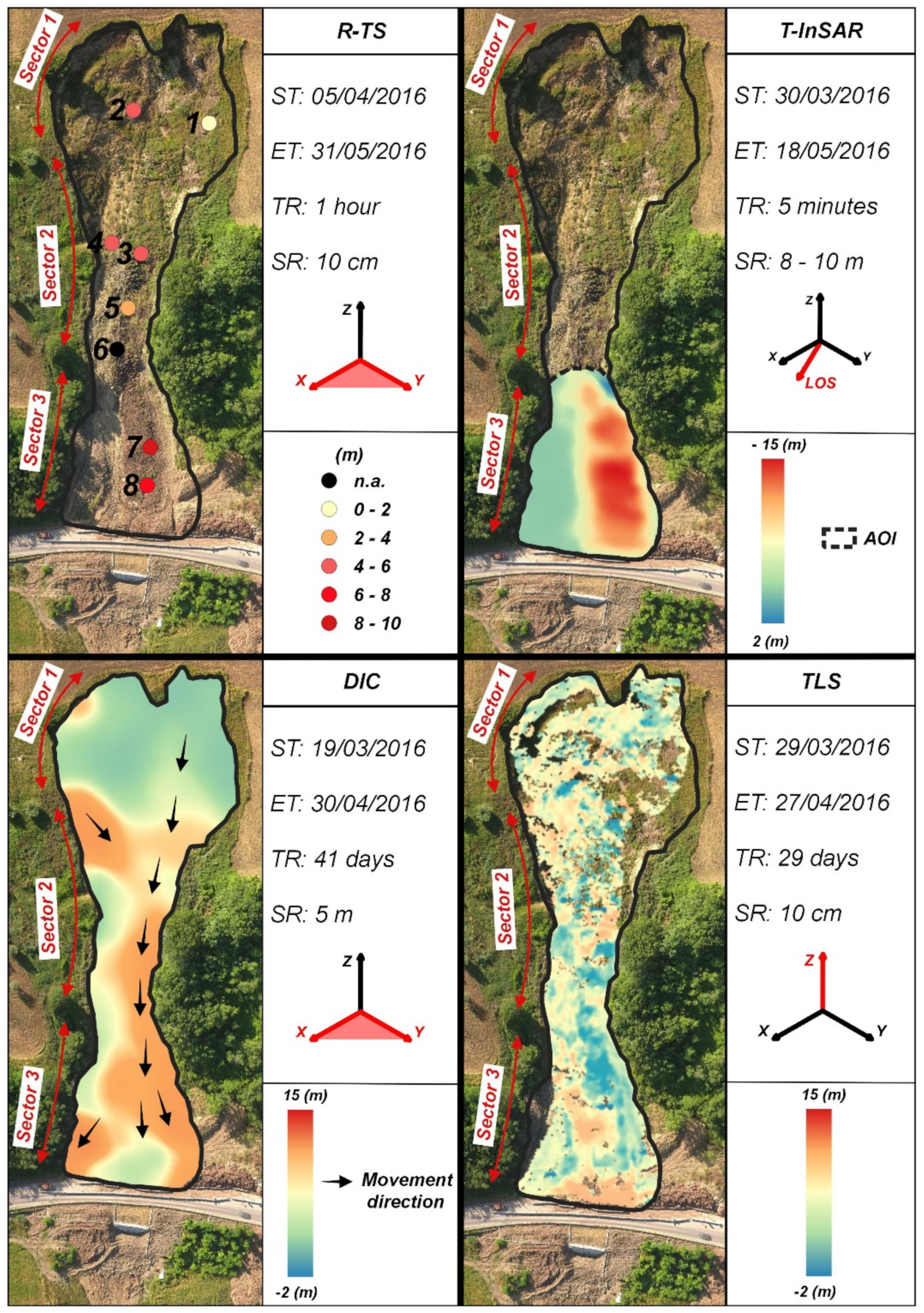
The analysis performed shows that the countless differences in terms of spatial and temporal resolution of the employed sensors and the variability in magnitude and geometry of the displacements produce outcomes that are not always easy to compare, as shown in Figure 9.
The R-TS and T-InSAR monitoring allowed us to obtain high-frequency and accurate data to be used for both the understanding of middle- to long-term behaviour and the short-term emergency management and risk reduction of the landslide. They returned comparable displacement data within certain movement velocities. The average displacement computed from T-InSAR data for the whole of Sector 3 was about 10 m, with the maximum pixel-based values being measured up to 15 m. On the other hand, the cumulative displacements reached at R-TS benchmarks 7 and 8, located in the same sector, were about 10 m and 7 m, respectively (Figure 9).
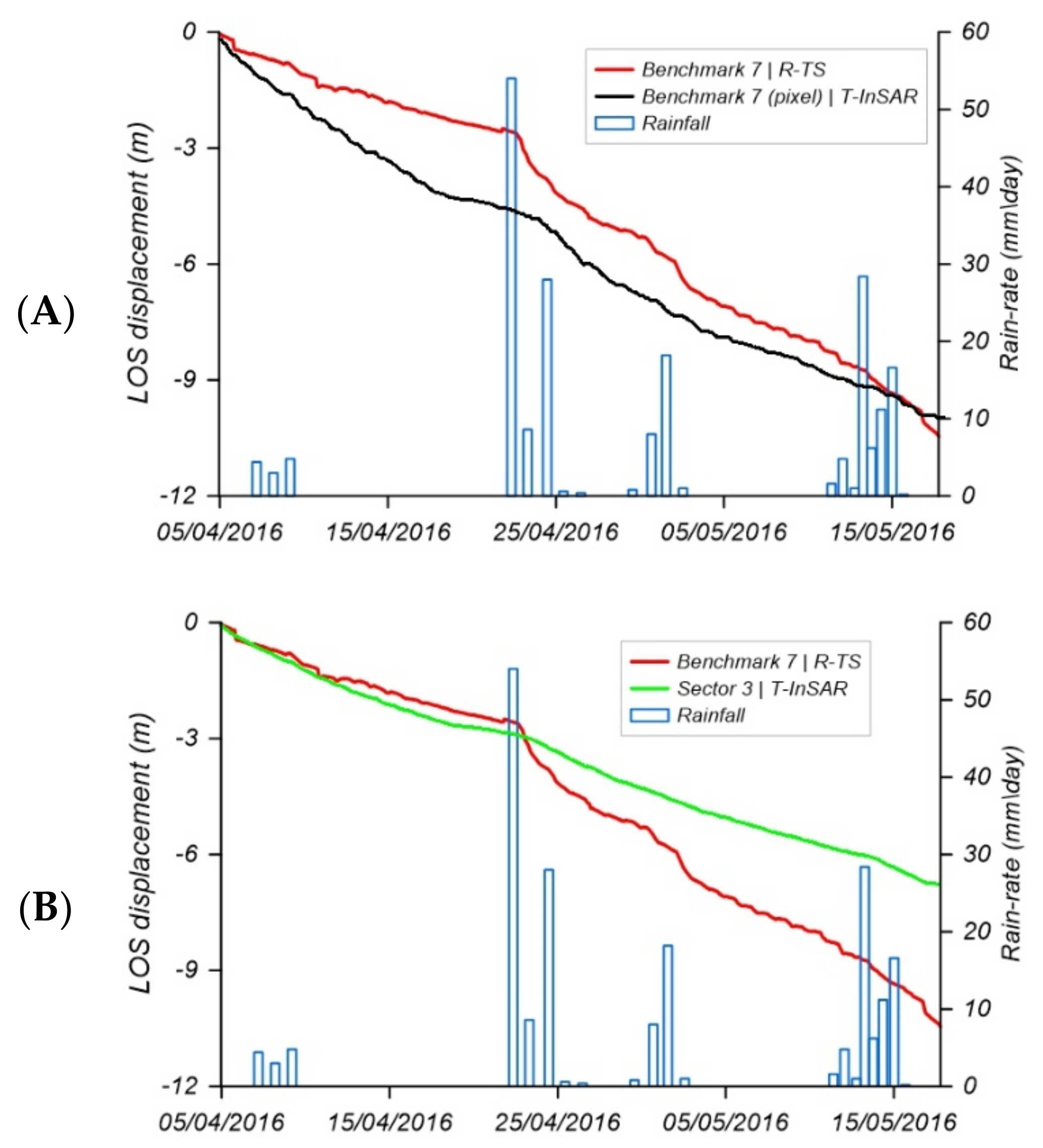
A qualitative comparison between R-TS and T-InSAR outputs was made, similar to that reported in [61], re-projecting R-TS data recorded at benchmark 7 alongside T-InSAR LOS. For this purpose, the pixel corresponding to the position of the same benchmark within the LOS displacement map was selected and the relative displacement time series was extracted. Similarly, the displacement time series relative to the whole of Sector 3 was obtained. Figure 10A shows the comparison made, indicating that, despite their different spatial resolutions (i.e., the T-InSAR time series is representative of a 3 m/pixel resolution, while the R-TS time series shows single-point detail), the deformation trends were coherent with external forcing.
Although there were non-negligible intra-curve differences in terms of velocity, the cumulative displacements differed slightly and the overall trends were consistent; such a discrepancy is likely due to the intrinsic varieties in the acquisition between the technologies (T-InSAR and R-TS). It is worth noting that, because of the presence of a larger number of pixels within Sector 3, the related area time series has a smoother shape (Figure 10B), being a mean value of all the pixels selected.
The displacement patterns recorded with both R-TS and T-InSAR are compatible with the values observed by several authors in the literature [24,28], who applied the same technologies for different earth flow monitoring tasks. In addition, the results of the present work show a clear correlation between R-TS and T-InSAR displacement data regarding the recorded rainfall events (Figure 6 and Figure 7), evidencing the key role of hydrologic force in these kinds of landslides [40].
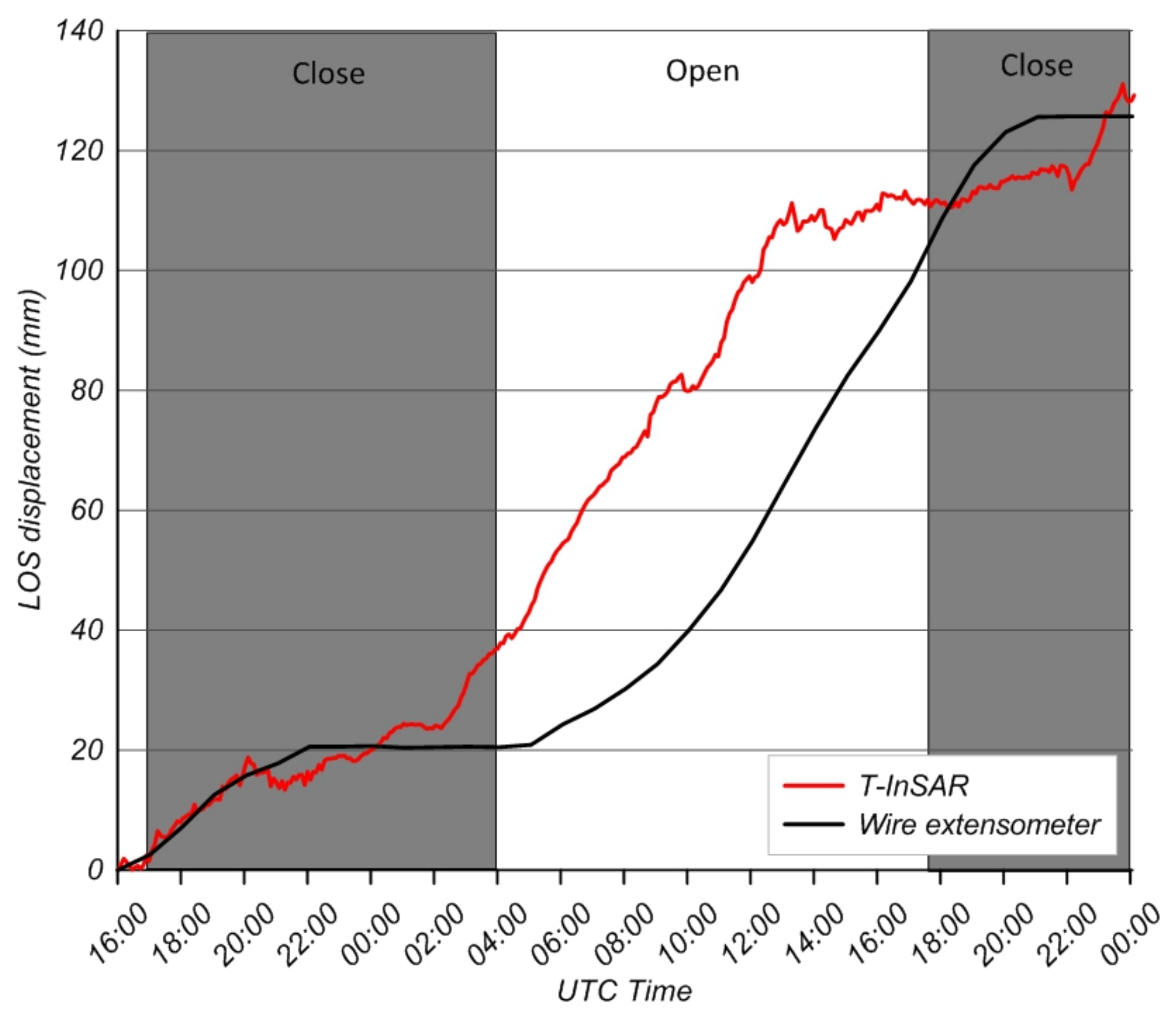
T-InSAR displacement data between 21 and 22 April 2016 were also coherent with wire extensometer displacement data recorded in the same period at the site of the Pietrafitta earth flow. This instrument, used at a seismic station, was installed along the left flank in Sector 3, in the context of the experiment conducted by [62], which aimed to demonstrate that, after 4–5 h of the night closure, the landslide movement stopped and then restarted simultaneously with the road day opening. This test proved that, even in the absence of rainfall events, the vibration induced by vehicle traffic acts as a trigger event of movement when geotechnical and geomorphological settings create ideal conditions for slope failure. In this context, our study revealed that T-InSAR is able to detect the same effects induced by this process (Figure 11). These results demonstrate that, after data elaboration and validation, an active remote sensing system located at an observed area distance of about 800 m with a coarse spatial resolution (i.e., cross-range) allows the retrieval of a similar displacement pattern to the one recorded by a local contact sensor such as a wire-extensometer. In addition to the intrinsic differences between technologies, the temporal shift visible in the curves is mainly linked to the different spatial resolutions of the sensors used. In other words, the benchmark of the wire extensometer is representative of a single point of displacement, while T-InSAR data are representative of an area of about 10 m2.
The combination of the techniques discussed above, while allowing a comprehensive understanding of the event, did not provide a global knowledge of the process. The use of the TLS technique and Satellite DIC fit into this context and were applied to close the knowledge gap. Through the use of TLS data, it was possible to reconstruct the intensity of the process that occurred in the period of interest. In fact, TLS data, unlike T-InSAR and R-TS data, can provide 3D volumetric information that is useful for understanding material discharge and sediment pulses. Between 29 March 2016 and 27 April 2016, the volume of material involved was 852.86 m3 (as shown in Section 4.3).
The displacement map obtained from the PhotoMonitoring analyses provided evidence that main movements were localised in Sector 2 and Sector 3 (Figure 8). As also reported in the literature [54,61,63], our work indicates that the displacements retrieved by this technique were underestimated, although the results are consistent in terms of the direction and location of the displacement when comparing the results obtained from T-InSAR and R-TS. The underestimation is likely due to the low geometrical resolution of RapidEye images that are not able to catch complex geomorphological features affecting the small size of the Pietrafitta earth flow. Overall, the analysis was able to detect a maximum displacement of around 4 m. More accurate results could be achieved by overcoming the “Single-couple” approach and performing a multi-master analysis [63], using Very High Resolution (VHR) images with a Ground Sampling Distance (GSD) of 5 metres. However, our solution indicates that the DIC analysis was able to achieve a precision of around 1/10th of a pixel, in accordance with the results of [52], which produced the same value employing optical and multispectral imagery.
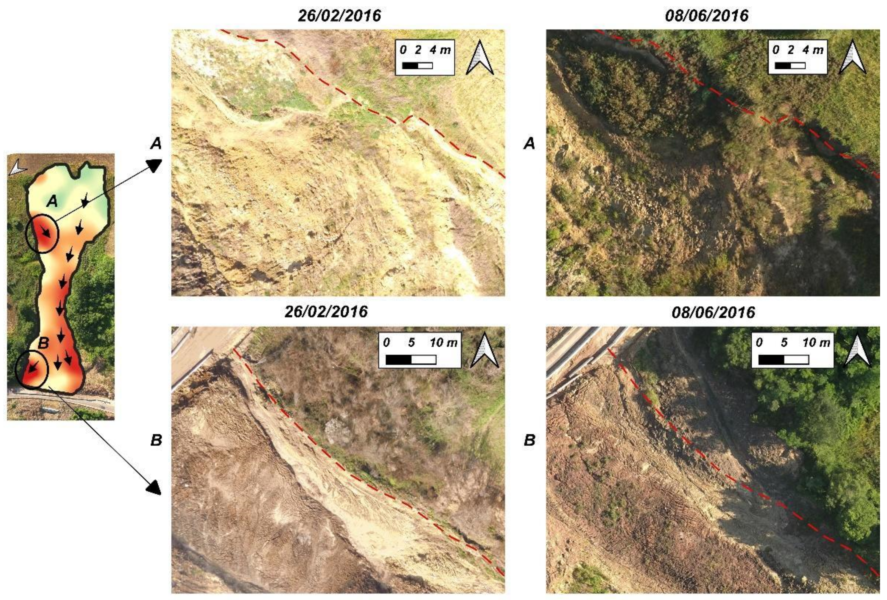
Despite the failure to fully detect the magnitude of the displacements that occurred, the results obtained from the PhotoMonitoring technique show some more deformations of the Pietrafitta earth flow that were not highlighted by T-InSAR and R-TS: (1) in Sector 2, an enlargement along the right flank (A in Figure 12) caused by the detachment of material from it, and (2) in Sector 3, an expansion zone at the right part of the toe (B in Figure 12), although the latter is an artefact due to the building of a drainage channel.
Since there are limited examples in the literature where remote sensing has been applied for the earth flow assessment, monitoring and possible failure time prediction [12,24,28], this paper aims to also provide the reader with a technical review of the most widely used methods in the field of engineering geology today, along with the most innovative methods which have shown the most promising results. As an example, the work carried out by Giordan et al. [24] focused on geomorphological long-term evolution (1954–2011) using aerial/satellite imagery, DEMs and topographic measurements, while Bardi et al. [29] manly focused on the role of T-InSAR during emergency monitoring.
Although, of course, the integration of technologies is often the solution to be pursued, and this should be a focus of landslide science in the next years [64], an overview of the main features of monitoring techniques applied to earth flows is provided in Table 6, with ratings based on the experiences of the members of this project during its conduction. Generally, it can be stated that, although T-InSAR has a high cost and involves complex deployment, it is able to reach a mm accuracy with very high temporal resolution and also allows emergency monitoring. In fact, in the present case study, the T-InSAR measurements detected a sudden acceleration of earth flow induced by an intense rainfall event (Figure 7C). It must be pointed out, however, that T-InSAR was only able to monitor Sector 3 with adequate accuracy along the LOS (corresponding to the earth flow toe).
R-TS measurements required the installation of prisms on the unstable slope but allowed us to extract 2D displacement measurements with a mm accuracy and adequate temporal resolution. Considering its use in earth flow processes, it is worth noting that the irregular surface deformations could cause the tilting and/or breaking of optical prisms, affecting the measurements, as happened in the present case.
TLS provides data with very high spatial resolution without using ground targets and can be effectively used to understand the amount of material mobilised using 3D volumetric information. The results from the Pietrafitta earth flow show that TLS monitoring, performed weekly, can provide useful data in terms of both vertical/horizontal deformation and the loss/gain of material for all the investigated sectors.
DIC does not require physical tools in the field and can be used with satellite data acquired several kilometres away from the unstable slope. Despite its low cost, it can be useful for observing the earth flow process as a whole. In the case of the Pietrafitta earth flow, due to the DIC results, some deformation processes were detected in areas that other techniques had failed to monitor (e.g., right flank, Figure 12). Overall, the algorithm used was able to detect a maximum displacement of around 4 m. Our work indicates that the displacements retrieved using this technique were underestimated.

6. Conclusions

The aims of this study were to characterise the ongoing gravitational process of the Pietrafitta earth flow and derive insights into the performance of different remote sensing techniques for the purposes of earth flow knowledge, control and emergency monitoring. Specifically, TLS, R-TS, T-InSAR and DIC technologies were applied, thus allowing us to understand the capabilities, peculiarities and limitations of the different techniques used in order to understand and monitor earth flow phenomena.
Taking into account the results achieved from each monitoring technique used, in the context of the present work, the following considerations can be made:
  • The results obtained from R-TS and T-InSAR were combined and compared in order to understand the deformation behaviour at different scales. This approach made it possible to observe that, despite the different resolutions of these techniques, the deformation trends recorded remained approximately consistent, with only the presence of differences mainly related to intrinsic acquisition inequalities between the technologies. Both techniques were proven to be reliable tools for evaluating the evolution of earth flows, allowing their typical characteristics to be highlighted, such as slow, localised and persistent movements and sensitivity to rainfall events (i.e., the variation of pore water pressure), resulting in the acceleration or deceleration of displacement rates.
  • Using the TLS measurements, it was possible to derive the volume of material that was mobilised during the period of maximum activity.
  • The use of the DIC technique by means of satellite images made it possible to study the deformation behaviour as a whole; using this technique also allowed us to observe a deformation zone, in Sector 2, with a tendency for the landslide body to widen along the right flank. This aspect was not evidenced with the other techniques previously used.
More generally, it has been shown that, when faced with a complex landslide, the synergic use of different monitoring techniques should be considered a standard approach in order to obtain a comprehensive understanding of the processes involved [64]. However, integrated approaches based on multi-sensor data still leave unresolved areas in applied research in earth flow monitoring today. For this reason, further studies are needed to broaden the experiences reported in this field and verify the considerations made. Within this framework, the following general points should be investigated in greater detail in future works:
  • The design and use of new integrated monitoring points to be installed in the field (e.g., corner reflectors for T-InSAR equipped with optical prisms for R-TS) would make the monitoring network more efficient, providing additional insights into measurement accuracies.
  • The use of orthophotos acquired from aerial platforms (e.g., UAVs) on a weekly basis would provide high-spatial- and temporal-resolution data that would constitute an excellent dataset for analysis using the DIC technique.
  • The use of increasingly automated systems that make it possible to fully exploit the potential of multi-sensor monitoring should be recommended, with the help of cutting-edge techniques such as machine learning.
  • The drafting of shared guidelines and standards regarding the monitoring instrumentation and techniques to be used in earth flow situations would lead to the spread of a set of best practices and better use of the monitoring solutions available today.

Author Contributions

Conceptualization, D.M., P.M., A.C. and P.R.; methodology, P.M., A.C. and D.M.; formal analysis, D.M.; investigation, D.M.; resources, D.M. and P.R.; data curation, D.M.; writing—original draft preparation, D.M., A.C. and S.R.; writing—review and editing, P.M., S.R., F.M.G. and P.R.; supervision, P.M. and P.R.; project administration, P.R. and F.M.G.; funding acquisition, P.R. and F.M.G. All authors have read and agreed to the published version of the manuscript.

Funding

This research was funded by University of Sannio by SIGMA Project (Proof of Concept, D.D. n. 467 of 02.03.2018—Area: Smart Secure and Inclusive Communities—Code: POC01_00071—CUP: F84I19000630008).

Data Availability Statement

Not applicable.

Acknowledgments

The authors wish to thank Luigi Guerriero, Neri Mascellaro and Gerardo Grelle for data collection, and Luigi Guerriero for providing the wire extensometer data.

Conflicts of Interest

The authors declare no conflict of interest.

References

  1. Revellino, P.; Grelle, G.; Donnarumma, A.; Guadagno, F.M. Structurally Controlled Earth Flows of the Benevento Province (Southern Italy). Bull. Eng. Geol. Environ. 2010, 69, 487–500. [Google Scholar] [CrossRef]
  2. Donnarumma, A.; Revellino, P.; Grelle, G.; Guadagno, F.M. Slope Angle as Indicator Parameter of Landslide Susceptibility in a Geologically Complex Area. In Landslide Science and Practice: Volume 1: Landslide Inventory and Susceptibility and Hazard Zoning; Margottini, C., Canuti, P., Sassa, K., Eds.; Springer: Berlin/Heidelberg, Germany, 2013; pp. 425–433. ISBN 978-3-642-31325-7. [Google Scholar]
  3. Keefer, D.K.; Johnson, A.M. Earth Flows: Morphology, Mobilization, and Movement; Professional Paper; U.S. Geological Survey: Washington, DC, USA, 1983; Volume 1264.
  4. Cruden, D.M.; Varnes, D.J. Landslide Types and Processes; Special Report—National Research Council; Transportation Research Board: Washington, DC, USA, 1996; pp. 36–75. [Google Scholar]
  5. Hungr, O.; Evans, S.G.; Bovis, M.J.; Hutchinson, J.N. A Review of the Classification of Landslides of the Flow Type. Environ. Eng. Geosci. 2001, 7, 221–238. [Google Scholar] [CrossRef]
  6. Hutchinson, J.N.; Prior, D.B.; Stephens, N. Potentially Dangerous Surges in an Antrim Mudslide. Q. J. Eng. Geol. Hydrogeol. 1974, 7, 363–376. [Google Scholar] [CrossRef]
  7. Handwerger, A.L.; Roering, J.J.; Schmidt, D.A. Controls on the Seasonal Deformation of Slow-Moving Landslides. Earth Planet. Sci. Lett. 2013, 377, 239–247. [Google Scholar] [CrossRef]
  8. Guerriero, L. Landslides and Infrastrucutres: The Case of the Montaguto Earth Flow in Southern Italy. Ital. J. Eng. Geol. Environ. 2013, 459–466. [Google Scholar] [CrossRef]
  9. Revellino, P.; Guerriero, L.; Ruzza, G.; Guadagno, F.M. Defining Kinematic and Evolutive Features of Earth Flows Using Integrated Monitoring and Low-Cost Sensors. In Understanding and Reducing Landslide Disaster Risk: Volume 3 Monitoring and Early Warning; Casagli, N., Tofani, V., Sassa, K., Bobrowsky, P.T., Takara, K., Eds.; ICL Contribution to Landslide Disaster Risk Reduction; Springer International Publishing: Cham, Switzerland, 2021; pp. 25–40. ISBN 978-3-030-60311-3. [Google Scholar]
  10. Bertello, L.; Berti, M.; Castellaro, S.; Squarzoni, G. Dynamics of an Active Earthflow Inferred From Surface Wave Monitoring. J. Geophys. Res. Earth Surf. 2018, 123, 1811–1834. [Google Scholar] [CrossRef]
  11. Vassallo, R.; Calcaterra, S.; D’Agostino, N.; De Rosa, J.; Di Maio, C.; Gambino, P. Long-Term Displacement Monitoring of Slow Earthflows by Inclinometers and GPS, and Wide Area Surveillance by COSMO-SkyMed Data. Geosciences 2020, 10, 171. [Google Scholar] [CrossRef]
  12. Calvello, M.; Peduto, D.; Arena, L. Combined Use of Statistical and DInSAR Data Analyses to Define the State of Activity of Slow-Moving Landslides. Landslides 2017, 14, 473–489. [Google Scholar] [CrossRef]
  13. Di Matteo, L.; Romeo, S.; Kieffer, D.S. Rock Fall Analysis in an Alpine Area by Using a Reliable Integrated Monitoring System: Results from the Ingelsberg Slope (Salzburg Land, Austria). Bull. Eng. Geol. Environ. 2017, 76, 413–420. [Google Scholar] [CrossRef]
  14. Romeo, S.; Di Matteo, L.; Kieffer, D.S.; Tosi, G.; Stoppini, A.; Radicioni, F. The Use of Gigapixel Photogrammetry for the Understanding of Landslide Processes in Alpine Terrain. Geosciences 2019, 9, 99. [Google Scholar] [CrossRef] [Green Version]
  15. Mazzanti, P. Toward Transportation Asset Management: What Is the Role of Geotechnical Monitoring? J. Civil. Struct Health Monit. 2017, 7, 645–656. [Google Scholar] [CrossRef]
  16. Lissak, C.; Bartsch, A.; De Michele, M.; Gomez, C.; Maquaire, O.; Raucoules, D.; Roulland, T. Remote Sensing for Assessing Landslides and Associated Hazards. Surv. Geophys 2020, 41, 1391–1435. [Google Scholar] [CrossRef]
  17. Mazzanti, P. Remote Monitoring of Deformation. An Overview of the Seven Methods Described in Previous GINs. Geotech. News 2012, 30, 24–29. [Google Scholar]
  18. Dei Cas, L.; Triglia, A.; Iadanza, C. Linee Guida per Il Monitoraggio Delle Frane. Linee Guid. SNPA 2021, 32, 2021. [Google Scholar]
  19. Malet, J.-P.; Maquaire, O.; Calais, E. The Use of Global Positioning System Techniques for the Continuous Monitoring of Landslides: Application to the Super-Sauze Earthflow (Alpes-de-Haute-Provence, France). Geomorphology 2002, 43, 33–54. [Google Scholar] [CrossRef] [Green Version]
  20. Guerriero, L.; Guerriero, G.; Grelle, G.; Guadagno, F.M.; Revellino, P. Brief Communication: A Low-Cost Arduino®-Based Wire Extensometer for Earth Flow Monitoring. Nat. Hazards Earth Syst. Sci. 2017, 17, 881–885. [Google Scholar] [CrossRef] [Green Version]
  21. Berti, M.; Simoni, A. Reactivation of a Dormant Earthflow Documented by Field Monitoring Data. EGU General Assembly Conference Abstracts, 2017. p. 6331. Available online: https://ui.adsabs.harvard.edu/abs/2017EGUGA..19.6331B/abstract (accessed on 20 December 2022).
  22. Guerriero, L.; Bertello, L.; Cardozo, N.; Berti, M.; Grelle, G.; Revellino, P. Unsteady Sediment Discharge in Earth Flows: A Case Study from the Mount Pizzuto Earth Flow, Southern Italy. Geomorphology 2017, 295, 260–284. [Google Scholar] [CrossRef]
  23. Mantovani, F.; Pasuto, A.; Silvano, S.; Zannoni, A. Collecting Data to Define Future Hazard Scenarios of the Tessina Landslide. Int. J. Appl. Earth Obs. Geoinf. 2000, 2, 33–40. [Google Scholar] [CrossRef]
  24. Giordan, D.; Allasia, P.; Manconi, A.; Baldo, M.; Santangelo, M.; Cardinali, M.; Corazza, A.; Albanese, V.; Lollino, G.; Guzzetti, F. Morphological and Kinematic Evolution of a Large Earthflow: The Montaguto Landslide, Southern Italy. Geomorphology 2013, 187, 61–79. [Google Scholar] [CrossRef]
  25. Bozzano, F.; Cipriani, I.; Mazzanti, P.; Prestininzi, A. Displacement Patterns of a Landslide Affected by Human Activities: Insights from Ground-Based InSAR Monitoring. Nat. Hazards 2011, 59, 1377–1396. [Google Scholar] [CrossRef]
  26. Mazzanti, P.; Bozzano, F.; Cipriani, I.; Prestininzi, A. New Insights into the Temporal Prediction of Landslides by a Terrestrial SAR Interferometry Monitoring Case Study. Landslides 2015, 12, 55–68. [Google Scholar] [CrossRef] [Green Version]
  27. Pieraccini, M.; Miccinesi, L. Ground-Based Radar Interferometry: A Bibliographic Review. Remote Sens. 2019, 11, 1029. [Google Scholar] [CrossRef] [Green Version]
  28. Ferrigno, F.; Gigli, G.; Fanti, R.; Intrieri, E.; Casagli, N. GB-InSAR Monitoring and Observational Method for Landslide Emergency Management: The Montaguto Earthflow (AV, Italy). Nat. Hazards Earth Syst. Sci. 2017, 17, 845–860. [Google Scholar] [CrossRef] [Green Version]
  29. Bardi, F.; Raspini, F.; Frodella, W.; Lombardi, L.; Nocentini, M.; Gigli, G.; Morelli, S.; Corsini, A.; Casagli, N. Monitoring the Rapid-Moving Reactivation of Earth Flows by Means of GB-InSAR: The April 2013 Capriglio Landslide (Northern Appennines, Italy). Remote Sens. 2017, 9, 165. [Google Scholar] [CrossRef] [Green Version]
  30. Baldo, M.; Bicocchi, C.; Chiocchini, U.; Giordan, D.; Lollino, G. LIDAR Monitoring of Mass Wasting Processes: The Radicofani Landslide, Province of Siena, Central Italy. Geomorphology 2009, 105, 193–201. [Google Scholar] [CrossRef]
  31. Clapuyt, F.; Vanacker, V.; Schlunegger, F.; Van Oost, K. Unravelling Earth Flow Dynamics with 3-D Time Series Derived from UAV-SfM Models. Earth Surf. Dynam. 2017, 5, 791–806. [Google Scholar] [CrossRef] [Green Version]
  32. Mugnai, F.; Caporossi, P.; Mazzanti, P. Exploiting Image Assisted Total Station in Digital Image Correlation (DIC) Displacement Measurements: Insights from Laboratory Experiments. Eur. J. Remote Sens. 2022, 55, 115–128. [Google Scholar] [CrossRef]
  33. Hermle, D.; Gaeta, M.; Krautblatter, M.; Mazzanti, P.; Keuschnig, M. Performance Testing of Optical Flow Time Series Analyses Based on a Fast, High-Alpine Landslide. Remote Sens. 2022, 14, 455. [Google Scholar] [CrossRef]
  34. Lacroix, P.; Araujo, G.; Hollingsworth, J.; Taipe, E. Self-Entrainment Motion of a Slow-Moving Landslide Inferred From Landsat-8 Time Series. J. Geophys. Res. Earth Surf. 2019, 124, 1201–1216. [Google Scholar] [CrossRef]
  35. Guerriero, L.; Di Martire, D.; Calcaterra, D.; Francioni, M. Digital Image Correlation of Google Earth Images for Earth’s Surface Displacement Estimation. Remote Sens. 2020, 12, 3518. [Google Scholar] [CrossRef]
  36. Daehne, A.; Corsini, A. Kinematics of Active Earthflows Revealed by Digital Image Correlation and DEM Subtraction Techniques Applied to Multi-Temporal LiDAR Data: KINEMATICS OF ACTIVE EARTHFLOWS. Earth Surf. Process. Landforms 2013, 38, 640–654. [Google Scholar] [CrossRef]
  37. Travelletti, J.; Oppikofer, T.; Delacourt, C. Monitoring Landslide Displacements during a Controlled Rain Experiment Using a Long-Range Terrestrial Laser Scanning (TLS); Chen, J., Jiang, J., Eds.; Hans-Gerd MAAS: Beijing, China, 2008; Volume XXXVII, Part B5, p. 6. [Google Scholar]
  38. Di Nocera, S.; Matano, F.; Pescatore, T.; Pinto, F.; Quarantiello, R.; Senatore, M.R.; Torre, M.L. Geological Scheme of the Transect Eastern Picentini-Southern Daunia Mts.: Stratigraphic Units and Tectonic Evolution of the Outer Zones of the Southern Apennines, Italy. Boll. Soc. Geol. Ital. 2006, 125, 39–58. [Google Scholar]
  39. Di Nocera, S.; Matano, F.; Torre, M. The “samnitic” Units Auct. (Central-Southern Apennines): Review of Current Palaegeographic and Stratigraphic Interpretations and New Hypotheses with the Introduction of the Unit of Frigento. 2002, 2002/1, pp. 87–102.
  40. Guerriero, L.; Diodato, N.; Fiorillo, F.; Revellino, P.; Grelle, G.; Guadagno, F. Reconstruction of Long-Term Earth-Flow Activity Using a Hydro-Climatological Model. Nat. Hazards 2015, 77, 1–15. [Google Scholar] [CrossRef]
  41. Guerriero, L.; Revellino, P.; Mottola, A.; Grelle, G.; Sappa, G.; Guadagno, F. Multi-Temporal Mapping of the Caforchio Earth Flow, Southern Italy. Rend. Online Della Soc. Geol. Ital. 2015, 35, 166–169. [Google Scholar] [CrossRef]
  42. Guerriero, L.; Coe, J.A.; Revellino, P.; Grelle, G.; Pinto, F.; Guadagno, F.M. Influence of Slip-Surface Geometry on Earth-Flow Deformation, Montaguto Earth Flow, Southern Italy. Geomorphology 2014, 219, 285–305. [Google Scholar] [CrossRef]
  43. Guerriero, L.; Focareta, M.; Fusco, G.; Rabuano, R.; Guadagno, F.M.; Revellino, P. Flood Hazard of Major River Segments, Benevento Province, Southern Italy. J. Maps 2018, 14, 597–606. [Google Scholar] [CrossRef] [Green Version]
  44. Revellino, P.; Guerriero, L.; Mascellaro, N.; Fiorillo, F.; Grelle, G.; Ruzza, G.; Guadagno, F. Multiple Effects of Intense Meteorological Events in the Benevento Province, Southern Italy. Water 2019, 11, 1560. [Google Scholar] [CrossRef] [Green Version]
  45. Castagnetti, C.; Bertacchini, E.; Corsini, A.; Capra, A. Multi-Sensors Integrated System for Landslide Monitoring: Critical Issues in System Setup and Data Management. Eur. J. Remote Sens. 2013, 46, 104–124. [Google Scholar] [CrossRef]
  46. Jaboyedoff, M.; Oppikofer, T.; Abellán, A.; Derron, M.-H.; Loye, A.; Metzger, R.; Pedrazzini, A. Use of LIDAR in Landslide Investigations: A Review. Nat. Hazards J. Int. Soc. Prev. Mitig. Nat. Hazards 2012, 61, 5–28. [Google Scholar] [CrossRef] [Green Version]
  47. Bitelli, G.; Dubbini, M.; Zanutta, A. Terrestrial Laser Scanning and Digital Photogrammetry Techniques to Monitor Landslide Bodies. Int. Arch. Photogramm. Remote Sens. Spat. Inf. Sci. 2004, 35, 246–251. [Google Scholar]
  48. Mazzanti, P.; Schilirò, L.; Martino, S.; Antonielli, B.; Brizi, E.; Brunetti, A.; Margottini, C.; Scarascia Mugnozza, G. The Contribution of Terrestrial Laser Scanning to the Analysis of Cliff Slope Stability in Sugano (Central Italy). Remote Sens. 2018, 10, 1475. [Google Scholar] [CrossRef] [Green Version]
  49. Bozzano, F.; Esposito, C.; Mazzanti, P.; Innocca, F.; Romeo, S. Urban Engineered Slope Collapsed in Rome on February 14th, 2018: Results from Remote Sensing Monitoring. Geosciences 2020, 10, 331. [Google Scholar] [CrossRef]
  50. Lague, D.; Brodu, N.; Leroux, J. Accurate 3D Comparison of Complex Topography with Terrestrial Laser Scanner: Application to the Rangitikei Canyon (N-Z). ISPRS J. Photogramm. Remote Sens. 2013, 82, 10–26. [Google Scholar] [CrossRef] [Green Version]
  51. Yu, S.; Wen, Y.; Chen, Z.; Zhang, G.; Wang, Y.; Hao, J.; Zhang, Q. A Rapid Gradation Detection System for Earth and Stone Materials Based on Digital Image. Adv. Civ. Eng. 2021, 2021, e6660301. [Google Scholar] [CrossRef]
  52. Caporossi, P.; Mazzanti, P.; Bozzano, F. Digital Image Correlation (DIC) Analysis of the 3 December 2013 Montescaglioso Landslide (Basilicata, Southern Italy): Results from a Multi-Dataset Investigation. ISPRS Int. J. Geo-Inf. 2018, 7, 372. [Google Scholar] [CrossRef] [Green Version]
  53. White, D.J.; Take, W.A.; Bolton, M.D. Soil Deformation Measurement Using Particle Image Velocimetry (PIV) and Photogrammetry. Géotechnique 2003, 53, 619–631. [Google Scholar] [CrossRef]
  54. Bickel, V.T.; Manconi, A.; Amann, F. Quantitative Assessment of Digital Image Correlation Methods to Detect and Monitor Surface Displacements of Large Slope Instabilities. Remote Sens. 2018, 10, 865. [Google Scholar] [CrossRef] [Green Version]
  55. Corvec, N.L.; Walter, T.R. Volcano Spreading and Fault Interaction Influenced by Rift Zone Intrusions: Insights from Analogue Experiments Analyzed with Digital Image Correlation Technique. J. Volcanol. Geotherm. Res. 2009, 183, 170. [Google Scholar] [CrossRef]
  56. Kääb, A. Monitoring High-Mountain Terrain Deformation from Repeated Air- and Spaceborne Optical Data: Examples Using Digital Aerial Imagery and ASTER Data. ISPRS J. Photogramm. Remote Sens. 2002, 57, 39–52. [Google Scholar] [CrossRef]
  57. Avouac, J.-P.; Ayoub, F.; Wei, S.; Ampuero, J.-P.; Meng, L.; Leprince, S.; Jolivet, R.; Duputel, Z.; Helmberger, D. The 2013, Mw 7.7 Balochistan Earthquake, Energetic Strike-Slip Reactivation of a Thrust Fault. Earth Planet. Sci. Lett. 2014, 391, 128–134. [Google Scholar] [CrossRef] [Green Version]
  58. Mugnai, F.; Cosentino, A.; Mazzanti, P.; Tucci, G. Vibration Analyses of a Gantry Structure by Mobile Phone Digital Image Correlation and Interferometric Radar. Geomatics 2022, 2, 17–35. [Google Scholar] [CrossRef]
  59. Stumpf, A. Landslide Recognition and Monitoring with Remotely Sensed Data from Passive Optical Sensors; University of Strasbourg: Strasbourg, France, 2013. [Google Scholar]
  60. Tong, X.; Ye, Z.; Xu, Y.; Gao, S.; Xie, H.; Du, Q.; Liu, S.; Xu, X.; Liu, S.; Luan, K.; et al. Image Registration With Fourier-Based Image Correlation: A Comprehensive Review of Developments and Applications. IEEE J. Sel. Top. Appl. Earth Obs. Remote Sens. 2019, 12, 4062–4081. [Google Scholar] [CrossRef]
  61. Dematteis, N.; Wrzesniak, A.; Allasia, P.; Bertolo, D.; Giordan, D. Integration of Robotic Total Station and Digital Image Correlation to Assess the Three-Dimensional Surface Kinematics of a Landslide. Eng. Geol. 2022, 303, 106655. [Google Scholar] [CrossRef]
  62. Guerriero, L.; Ruzza, G.; Maresca, R.; Guadagno, F.M.; Revellino, P. Clay Landslide Movement Triggered by Artificial Vibrations: New Insights from Monitoring Data. Landslides 2021, 18, 2949–2957. [Google Scholar] [CrossRef]
  63. Mazzanti, P.; Caporossi, P.; Muzi, R. Sliding Time Master Digital Image Correlation Analyses of CubeSat Images for Landslide Monitoring: The Rattlesnake Hills Landslide (USA). Remote Sens. 2020, 12, 592. [Google Scholar] [CrossRef] [Green Version]
  64. Casagli, N.; Intrieri, E.; Tofani, V.; Gigli, G.; Raspini, F. Landslide Detection, Monitoring and Prediction with Remote-Sensing Techniques. Nat. Rev. Earth Environ. 2023, 4, 51–64. [Google Scholar] [CrossRef]
Figure 1. (A) Location of the Pietrafitta earth flow within the Reventa river valley. (B) Distribution of the main kinematic elements along the slope. Basemap: orthophoto and Digital Surface Model (DSM) acquired during a UAV survey in February 2016.
Remotesensing 15 01138 g001
Figure 2. (A) Dataset temporal distribution. (B) TOPCON 101 Robotic Total Station. (C) distribution of R-TS optical prisms along the slope. Basemap: orthophoto acquired during UAV survey in June 2016. The yellow dots represent the reference points installed in areas considered stable. The red dots represent the optical prisms relocated. (D) Position of the IBIS-FL/FM radar device. (E) Riegl Scan VZ-4000 Terrestrial Laser Scanner on the slope opposite the Pietrafitta earth flow.
Remotesensing 15 01138 g002
Figure 3. T-InSAR System: schematisation of the system and its components (image from IBIS Guardian User Manual).
Remotesensing 15 01138 g003
Figure 4. Schematisation of the DIC process.
Remotesensing 15 01138 g004
Figure 5. (A) Distribution of the benchmarks along the slope. Basemap: orthophoto acquired during UAV survey in June 2016. (B) Correlation between planimetric displacement for selected targets and rainfall events: coloured lines represent the displacement cumulative time series while vertical bars represent the daily rain data.
Remotesensing 15 01138 g005
Figure 6. (A) LOS displacement map. The raster raw data (3 m/pixel) were resampled (1 m/pixel) only for visualisation purposes. Each pixel of the image shows the cumulative displacement recorded in 48 days of observation. Negative and positive values indicate movement towards and away from the instrument, respectively. The black line represents the landslide boundary. The dashed black line represents the Sector 3 boundary. Basemap: orthophoto acquired during UAV survey in June 2016. (B) Average displacement time series for Sector 3 from 30 March 2016 to 17 May 2016. (C) Average displacement time series for Sector 3 from 21 April 2016 to 27 April 2016. The light-blue box represents the 23 April rainfall event.
Remotesensing 15 01138 g006
Figure 7. Vertical displacement map computed through 29 March 2016 and 27 April 2016 scans. The results are overlaid on the June 2018 3D model of the slope. Raising and lowering of the topographic surface are indicated with red and blue colours, respectively.
Remotesensing 15 01138 g007
Figure 8. Results obtained from Digital Image Correlation (DIC) analysis. Displacement map projected on June 2016 orthophoto. The raster raw data (5 m/pixel) were resampled (1 m/pixel) only for visualisation purposes. Each pixel of the image shows the displacement computed on variable window comparing master (19 March 2016) and slave image (30 April 2016).
Remotesensing 15 01138 g008
Figure 9. Summary and comparison of the monitoring results. ST: start-time; ET: end-time; TR: temporal resolution; SR: spatial resolution. The R-TS spatial resolution refers to the optical prisms dimension. The red, right-handed Cartesian axes and planes represent the direction and the field of displacements, respectively, to which the results refer.
Remotesensing 15 01138 g009
Figure 10. (A) Comparison between point-based displacement time series and (B) point-based/area-based displacement time series.
Remotesensing 15 01138 g010
Figure 11. Modified from [62]: correlation between artificial vibration generated by vehicular traffic and earth flow displacement between 16:00 (UTC +2) on 21 April 2016 and 00:00 (UTC +2) on 22 April 2016. The red line shows the displacement time series extracted from pixels corresponding to wire extensometer positions within T-InSAR LOS displacement map.
Remotesensing 15 01138 g011
Figure 12. Visual comparison of the orthophotos acquired before and after the period analysed with DIC (19 March 2016–30 April 2016) confirmed the presence of two widening zones along the right flank of the earth flow. The dashed red line represents the earth flow boundary in February 2016.
Remotesensing 15 01138 g012
Table 1. Characteristics of radar sensor IBIS-FL/FM installed on the Pietrafitta earth flow.
Operating Frequency17.2 GHz (Ku Band)
Max. Operational Distance1000 m
Max. Range Resolution0.5 m
Nominal Displacement Accuracy10−5 m
Max. Acquisition Rate200 Hz
Cross-range Resolution4.4 mrad in Ku band
Table 2. Characteristics of Laser Scanner RIEGL VZ-4000.
AccuracyPrecisionLaser WavelengthMinimum RangeMaximum RangeLaser Beam DivergenceLaser Beam Footprint
15 mm10 mmNear infrared5 m4000 m0.15 mrad150 mm @ 1000 m
Table 3. Scans carried out at the site of the Pietrafitta landslide during the period of interest.
MonthNumber of ScansDates
March129 March 2016
April36 April 2016
11 April 2016
27 April 2016
May24 May 2016
30 May 2016
Table 4. Image used for DIC analysis.
Name ImagesDate
3358114_2016-03-19_RE4_3A_Analytic_SR_519 March 2016
3358114_2016-04-30_RE3_3A_Analytic_SR_530 April 2016
Table 5. Displacement rates measured between 18–22 April (T1) and 23–27 April (T2).
BenchmarkDisplacement Rate T1 (m/day)Displacement Rate T2 (m/day)
2<0.01~0.019
3<0.01~0.018
4<0.01~0.018
6~0.01~0.011
7~0.07~0.035
8~0.06~0.028
Table 6. Overview of the main features of monitoring measurements carried out at the site of the Pietrafitta earth flow. The capability ratings for each parameter on earth flow monitoring are given in parentheses.
TechniquesAccuracy ReachedSpatial ResolutionTemporal ResolutionRangeTargetsPresumed CostDeployment
R-TSmm
(+)
Measurements on prisms (−)1 h800 m (+)Yes
(−)
€€Complex
T-InSARmm
(+)
8–10 m
(−)
5 min
(+)
800 m (+)No
(+)
€€€Complex
TLScm10 points/cm2
(+)
Weeks800 m (+)No
(+)
€€Difficult
DICdm5 mMonths (−)km
(+)
No
(+)
No hardware required
Disclaimer/Publisher’s Note: The statements, opinions and data contained in all publications are solely those of the individual author(s) and contributor(s) and not of MDPI and/or the editor(s). MDPI and/or the editor(s) disclaim responsibility for any injury to people or property resulting from any ideas, methods, instructions or products referred to in the content.