Abstract
Synthetic aperture radar (SAR), as an active microwave sensor, can inevitably receive radio frequency interference (RFI) generated by various electromagnetic equipment. When the SAR system receives RFI, it will affect SAR imaging and limit the application of SAR images. As a kind of RFI mitigation method, notch filtering method is a classical method with high efficiency and robust performance. However, the notch filtering methods pay no attention to the protection of useful signals. This paper proposed a modified 2-D notch filter based on image segmentation for RFI mitigation with signal-protected capability. (1) The adaptive gamma correction (AGC) approach was utilized to enhance the SAR image with RFI in the range-frequency and azimuth-time domain. (2) The modified selective binary and Gaussian filtering regularized level set (SBGFRLS) model was utilized to further process the image after AGC to accurately extract the contour of the useful signals with interference, which is more conducive to protecting the useful signals without interference. (3) The Generalized Singular Value Thresholding (GSVT) based low-rank sparse decomposition (LRSD) model was utilized to separate the RFI signals and the useful signals. Then, the useful signals were restored to the raw data. The simulation experiments and measured data experiments show that the proposed method can effectively mitigate RFI and protect the useful signals whether there are RFI with single source or multiple sources.
1. Introduction
1.1. Background
Synthetic aperture radar (SAR) is an active microwave technology that can observe the Earth all-day and during all-weather. SAR can be applied in many fields such as crop yield estimation, ground feature classification, marine environment monitoring, and military reconnaissance, etc. [1,2,3,4,5,6,7,8]. However, as an active wideband radio system, SAR can easily receive RFI signals, and these RFI signals will seriously degrade the SAR imaging quality and limit the application of SAR images. Over the past few decades, with the rapid development of electronic information field and modern radio technology, radio frequency interference (RFI) existing in SAR images has become a common phenomenon [9,10,11,12,13]. Figure 1 shows the common sources of RFI.
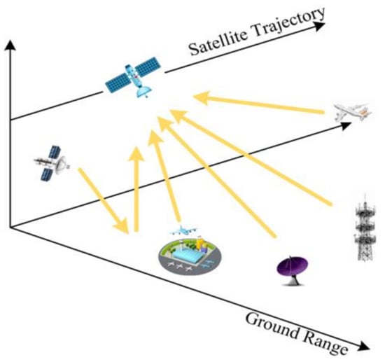
Figure 1.
Common sources of RFI.
For increasingly complex RFI, it is necessary to propose some effective mitigation methods. Using scientific and effective RFI mitigation methods is beneficial to improving the survivability and practical efficiency of SAR systems in complex electromagnetic environments, and it has important practical significance. With the further development of SAR technology, researchers have proposed many mitigation methods for different types of RFI [14]. Parametric methods, semiparametric methods, and nonparametric methods are three types of RFI mitigation methods to mitigate the interference. Parametric methods and semiparametric methods can mitigate the RFI to a certain extent by adjusting the determined model and parameters. For example, Zhou et al. [15] proposed an algorithm of wideband interference suppression via instantaneous frequency estimation and regularized time-frequency filtering. Huang et al. [16,17,18,19,20,21] carried out an in-depth study on semiparametric methods and proposed a series of low rank and sparse decomposition models. Recently, they proposed an algorithm of time-varying RFI mitigation via graph Laplacian clustering techniques [22]. Braunstein et al. [23] mitigated the RFI in measured data by the parametric method. Zhang et al. [24] used wavelet transform and short-time Fourier transform to analyze the characteristics of interference in the 2-D range time–frequency domain. Yang et al. [25] proposed a postprocessing kernel, namely, the 2-D SPECtral ANalysis (2-D SPECAN) filter, to remove the RFI in SLC images. In recent years, the RFI mitigation algorithm combined with machine learning has achieved good results. Zhou et al. [26] presented a narrow-band interference and wide-band interference mitigation algorithm based on the deep residual network, and Xu et al. [27] proposed two RFI mitigation algorithms based on a modified block sparse Bayesian learning, and these algorithms have achieved a good mitigation effect. However, these above methods rely on the estimation of model parameters, and the type of interference aimed by these methods is relatively single, so the generalizability of this kind of method is relatively weak. On the other hand, nonparametric methods mitigate RFI through the characteristics of the useful signals and the RFI signals in different domains. Nonparametric methods not only have applicability and robustness, but also have high algorithm efficiency, and there is no need to establish a model of RFI. Zhou et al. [28,29,30,31] proposed a series of algorithms based on matrix decomposition theory, Yang et al. [32] proposed a generic subspace model for characterizing a variety of RFI types and designed a block subspace filter for removing RFI artifacts in SLC SAR images. In particular, the most classic nonparametric method is the notch filtering method, and the main principle of the notch filtering method is to set the RFI signal to zero and achieve the purpose of mitigating RFI. However, there is a flaw in these nonparametric methods: when the RFI signals are mitigated, part of the useful signals will be lost, so it is necessary to improve the notch method [33,34,35,36,37,38].
1.2. Previous Work of Notch Method
Since the 1990s, various advanced nonparametric methods have been proposed to mitigate RFI. In 1996, Cazzaniga and Guarnieri proposed the MUSIC method to estimate narrow-band interference frequencies [39]. Subsequently, in order to improve the detection probability for the peaks, Buckreuss and Horn proposed an averaging of the spectra of adjacent range lines, which was first applied to the E-SAR systems [40]. Meyer et al. designed adaptive detection to determine the RFI locations of narrow-band, wide-band, and determined the notch filter width to design a RFI mitigation process; this method was well validated in the ALOS PALSAR data [41].
Researchers have proposed a series of adaptive notch methods [42,43,44,45,46,47,48,49], which have a good compromise in terms of convergence speed, stability, computational complexity, and adaptation. The InTernational Union of Radio science (ITU-R) in its report also provides similar recommendations for the notch filter to enable its application in the Earth Exploration Satellite Service (EESS) [50]. Nabil et al. showed that there was a special near-zero RFI in the TarraSAR-X data, and proposed a modified notch filter based on the traditional notch filter to obtain two images after two mitigations, then combined them to obtain better azimuth spectrum information [51]. In [52], a sub-band spectral phase cancellation method was proposed to use the difference between adjacent spectral sub-bands to approximate the effect of the notch filter, and applied to the SAR data. The above-mentioned notch filters are mainly applied to raw data, and Reigber and Doerry proposed a new notch filtering method to eliminate the interference from the focused image and verified it on the L-band SAR data, respectively [53,54]. In [55], an azimuth-frequency domain filtering method was proposed to suppress the intermittent transmission interference in the 2-D range-time domain and azimuth-frequency domain. Li et al. proposed a time domain notch filtering (TNF) method for pulse RFI mitigation in SAR [56].
However, the drawback of the above notch filter is that when the zero-notch width of the filter exceeds 2% of the bandwidth, the spatial resolution will decrease, and the sidelobe energy will increase. Therefore, it is necessary to further improve the notch filtering method.
1.3. Main Contributions of This Paper
In order to improve the protection ability of notch filtering methods for useful signals, this paper proposed a modified 2-D notch filter based on image segmentation. First, inspired by the idea of traditional notch filtering method, the raw data were converted to the range-frequency and azimuth-time domain, the characteristics of RFI were analyzed. The image of range-frequency and azimuth-time domain was enhanced by adaptive gamma correction (AGC). Then, the modified selective binary and Gaussian filtering regularized level set (SBGFRLS) model was utilized to segment the image, and the RFI signals were extracted. Finally, the Generalized Singular Value Thresholding (GSVT) -based low-rank sparse decomposition (LRSD) model was performed on the extracted part to screen out the useful signals and the RFI signals and restore the useful signal to the initial raw data. The specific contributions of this paper are as follows:
- The method proposed combines the image segmentation technology with RFI mitigation to accurately extract the contour of the useful signals with interference, which is more conducive to protecting the useful signals without interference.
- The GSVT-based LRSD model was performed to further extract the useful signals contained in the RFI signals. The proposed method effectively improves the protection ability of the useful signals compared with the traditional notch filtering method.
- The superiority of the proposed method was verified by simulation experiments and measured data experiments. The proposed method can effectively mitigate RFI and protect the useful signals, whether there are RFI with a single source or multiple sources.
The remainder of this article is organized as follows. In Section 2, the geometric and signal models are introduced, and classical frequency domain notch filtering (FNF) is introduced. Section 3 shows the technical route of the algorithm proposed in this paper. Section 4 shows the experimental results and performance analysis of the proposed method. Section 5 discusses the experiments in this paper. Section 6 presents our conclusions and future work.
2. Model and Related Work
2.1. Signal Model of RFI
In the SAR system, the signals exist in the 2-dimensional time domain. After quadrature demodulation and digital sampling, the raw data received by the SAR system can be written as
where represents the useful signal; represents the RFI signal; represents the system noise; and denote the range fast time and the azimuth slow time, respectively.
In general, the signal model interference can be expressed as
where represents the number of the RFI signals. , , and represent the amplitude, frequency, and phase of the th interference signal, respectively.
This can be divided in two terms, where represents the linear frequency modulation (LFM). We can obtain:
where represents the chirp rate of the th signal, and represents the modulation factor.
Normally, the SAR system transmits the LFM signal, which is expressed as
where represents the window function; is the SAR signal receiving duration; is the frequency modulation rate of the transmitted signal; and represents the signal transmission delay. The signal received by the SAR system after transmission delay is:
2.2. Theory of FNF
The FNF method is a classical nonparametric interference mitigation method, which not only has applicability and robustness, but also has high algorithm efficiency. The FNF method has been widely used to solve the problem of RFI in airborne SAR and spaceborne SAR systems [57].
First, the frequency domain representation of needs to be obtained because the FNF method is a frequency domain processing method. Therefore, the stationary phase method (SPM) is used, and the approximate signal spectrum of can be expressed as
where and represent the range sampling rate and bandwidth of signal, respectively. represents the constant.
According to Equation (1), assuming that the raw data contains RFI signal and system noise , we used SPM to obtain the approximate signal spectrum of . In general, the system noise can be negligible. For the sake of derivation, the constant term , phase term and system noise can be ignored. The approximate signal spectrum of the signal received by the SAR system can be rewritten as:
To show the difference between the RFI signal and the useful signal more clearly, we performed 1-dimensional range direction Fourier transform (FT) on the raw data containing RFI with single sources and multiple sources, and the 3-dimensional diagram is shown in Figure 2. Among them, Figure 2a shows the data containing RFI with a single source, Figure 2b is the data containing RFI with multiple sources, and the inside of the red ellipse represents the RFI signals.
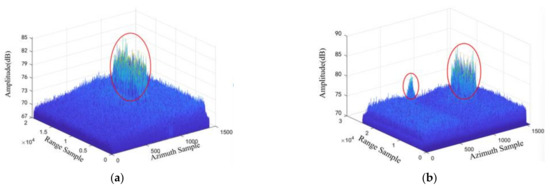
Figure 2.
The 3-dimensional diagram in the range-frequency and azimuth-time domain. (a) The data containing RFI with a single source. (b) The data containing RFI with multiple sources.
We defined and to represent the interference frequency and bandwidth, respectively. , the filter can be expressed as:
In order to focus the signal received by the SAR system, we performed matched filtering processing, and the match filter function is
At the same time, we need to multiply the signal by the notch filter in the frequency domain processing, and we can obtain:
Since the notch filter sets the frequency components of the RFI signal to zero, that is, , Equation (10) can be rewritten as:
Then, is transformed to a 2-dimensional time domain, and the impulse response of the output signal can be expressed as
where and represent the amplitude response. According to the above derivation process, it can be seen that the frequency domain notch filter will eliminate the frequency components of the interference in the SAR signal, but it will be mixed with the frequency components of the useful signal. Therefore, the FNF method can suppress the RFI, but it cannot protect the useful signals, which will lead to the degradation of the image quality.
2.3. Low-Rank Characteristics of RFI
The RFI in the range-frequency domain has a relatively stable frequency in the slow time direction, and its amplitude appears as some parallel straight lines, as shown in Figure 3a. It is clear that RFI has low-rank properties in the slow time direction. For further verification, the eigenvalue decomposition of Figure 3a was performed, and the corresponding results are shown in Figure 3b, the red line represents percentage. The eigenvalues reflect the energy of different components in the SAR echo and the structural redundancy of the matrix. As can be observed, only a few large eigenvalues were related to RFI, which further illustrates the low-rank feature of RFI in the range-frequency domain.
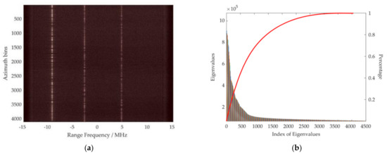
Figure 3.
Structural analysis of RFI in the range-frequency domain. (a) Spectrogram of SAR echoes contaminated by RFI. (b) Eigenvalue sequences and analysis corresponding to (a).
3. Methodology
To solve the problem of RFI mitigation in SAR data, a modified 2-D notch filter method was proposed. The proposed method consists of three steps: enhancing the image in the range-frequency and azimuth-time domain by AGC; segmenting the edge of the RFI areas by the modified SBGFRLS model; and extracting the RFI signals to leave the useful signals by GSVT-based LRSD. The proposal can mitigate RFI robustly, and protect the useful signals effectively. The specific flowchart is shown in Figure 4.
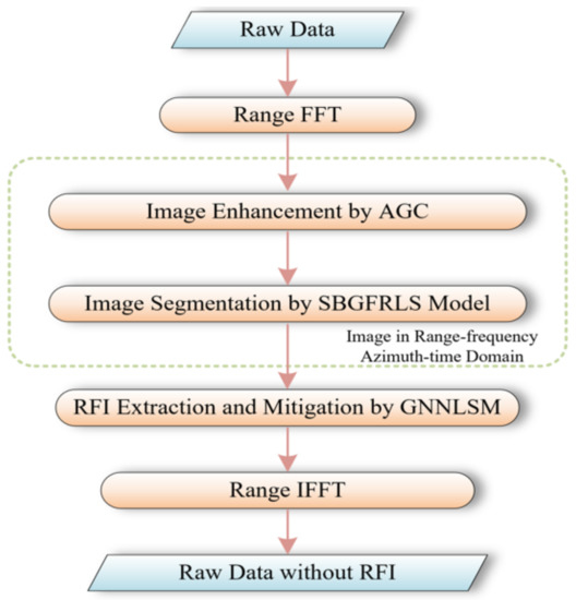
Figure 4.
Flowchart of the proposed method.
3.1. Image Enhancement by AGC
AGC is an algorithm in the field of image processing, and is an improvement algorithm of gamma correction (GC) [58]. AGC can stretch the intensity level of the image and reduce the number of low intensity cells while increasing the number of high intensity cells. The AGC is used to enhance the range-frequency and azimuth-time domain image of SAR data with RFI, and this operation will enhance the discrimination between signals of RFI and useful signals.
First, we set a parameter ; the GC algorithm adjusts the pixel value of the image by changing the size of parameter . The GC is formulated as follows:
where is the maximum intensity of the input. The intensity of each pixel in the input image is transformed as after performing Equation (13).
The AGC algorithm uses a cumulative distribution function to replace the of the GC algorithm. The AGC is formulated as follows:
where represents the cumulative distribution of the intensity . By calculating the probability density function, as shown in Equation (15):
where represents the sum of the probability density of the whole image, and can be calculated as follows:
where refers to the probability function after adjusts the histogram through the weighting distribution. The weighting distribution function is formulated as:
where is the adjusted parameter; is the maximum of the statistical histogram; and is the minimum . These two parameters and are empirical values, and we generally set them as 0.1–1.5. The intensity of the pixels in the image will vary with the parameters. The larger the parameter, the higher the intensity. In this paper, we compared the treatment effect through experiments. When they were in the range of 0.2–0.6, we could obtain a better result after the process.
In the image after AGC, the signals of RFI will be more obvious than the useful signals, which is equivalent to the first separation of the useful signals and RFI signals in the proposed algorithm. This operation will greatly improve the accuracy of image segmentation in the next step.
3.2. Image Segmentation by the SBGFRLS Model
The active contour model (ACM) is deformed contours that move under the force of the image and external constraints [59]. At present, ACM is generally divided into four categories: threshold based, edge based, region based, and energy functional based. According to the analysis in Section 2, the ACM based on region is more suitable for image segmentation in this paper. In the range-frequency and azimuth-time domain, the pixel intensity of RFI is usually high, and the pixel intensity in some areas is significantly higher than that of useful signals, while region-based ACM generally uses the overall intensity of the internal and external areas for segmentation. Therefore, region-based ACM is more suitable for this situation.
Among them, SBGFRLS is a kind of region-based ACM algorithm realized by selecting binary and Gaussian filter regularization, which is more suitable for image segmentation in the range-frequency and azimuth-time domain. In the range-frequency and azimuth-time domain, the strength of the RFI signals is generally significantly stronger than the strength of useful signals. However, when there are strong point targets in the region of interest such as ships at sea, corner reflectors in a certain area on land, etc., the raw data of these objects will affect image segmentation after image enhancement. Using the improved SBGFRLS algorithm can reduce the impact of these “noises” and improve the edge extraction accuracy for RFI, but the algorithm is not sensitive to the selection of the initial contour. Compared with traditional segmentation algorithms, image segmentation in this case has obvious advantages. Therefore, the modified SBGFRLS model was utilized to further process the image after AGC and accurately extract the contour of the RFI signals, and useful signals can exist, which is more conducive to protecting the signals without RFI [60]. The algorithm uses the Euclid length term to regularize the contour curve, and adds the average gray values inside and outside the curve to the SBGFRS model. The algorithm reduces the influence of other “noise” targets and is insensitive to the selection of initial contour.
Deformation energy can represent the contours of the target area, and external force on the contour, potential energy, and total energy represent the individual model functions that affect edge segmentation [59]. A suitable deformation energy is assumed to define the contour of the target, represents the contour, and it means the mapping from the unit parameter domain to the image, while considering the external force on the contour as a differential of the potential energy . Then, the total energy on the contour can be defined as:
with
where represents the differential with respect to , and an internal deformation energy of a stretchable and bendable contour is defined by , and the consists of two parameters: the “stress” of the contour is controlled by , the “stiffness” of the contour is controlled by , these parameters control the physical behavior and local continuity of the model. In particular, assuming that , the discontinuous position of is allowed, and the discontinuous on tangent of the point is allowed. The external potential energy can be expressed as:
where is a scalar function defined over the entire image surface . When the external binding force is not considered, if , the contour edge will be attracted to the area of low or high intensity; if , the contour edge will be attracted to the edge of the region of interest. Among them, controls the magnitude of the potential energy, and represents the convolution of the image and Gaussan smoothing filter with feature density . The above model is conducive to unifying the target contour in a feature extraction process, and after properly initialized, it can autonomously converge to an energy minima state.
According to Equations (18)–(20), we have:
where represents the functionals of the , if obtains the extreme value on a certain curve, Equation (21) satisfies the follow Equation:
Therefore, the minimum value of the region can be obtained by solving the above Equation to obtain the edge of the target contour. The above is the process of classical ACM. Then, the modified SBGFRLS model was utilized to solve Equation (22). We assume that the internal and external average gray value are and :
where is the image after AGC; is the level set function; represents the heaviside function. Then, the indicator function can be expressed as:
where represents the maximum in region. We can obtain the following level set Equation:
where represents the time; represents the gradient operation; represents the growth power, which is used to control the contraction or expansion of the contour.
Finally, the image region can be segmented by iteratively judging whether the level set function converges according to the above equation. Although we successfully segmented the part of RFI in the range-frequency and azimuth-time domain using the modified SBGFRLS model, there were still useful signals in the extracted part. In the process of radar receiving signals, RFI was mixed with useful signals and entered the receiver at the same time. Therefore, we can understand that RFI actually covers the useful signals, but we only divided the parts with RFI, and did not protect the useful signals in the parts with RFI. In order to protect useful signals, we need to further process the area after image segmentation.
3.3. RFI Extraction by GSVT
RFI has low rank characteristics in the range-frequency and azimuth-time domain. Therefore, we can use the LRSD model to further process the signals after segmentation, and the useful signals can be effectively protected by solving the LRSD problem. The GSVT is an effective method to solve the LRSD problem. Through the analysis in Section 2, the GSVT is suitable for RFI mitigation because of the characteristics of RFI. LRSD, also known as the robust principal component analysis (RPCA) algorithm, is currently applied in many fields, for example, moving and stationary target separation in the SAR signal domain using parallel convolutional autoencoders with RPCA loss [61]. Separating the sparse matrix of moving targets from the low-rank matrix of static backgrounds by RPCA was conducted in [62], and the GSVT-based LRSD was utilized in this paper [63]. As a LRSD method, this method can better obtain the compromise factor from the observed data and solve the proposed GSVT problem through the alternating direction multiplier method (ADMM). Compared with the traditional LRSD method, this method has a better denoising effect, and the effect of protecting useful signals is better than the traditional method. The formulation of this model can be expressed as:
where represents the rank of the matrix; represents the norm of the matrix, the number of non-zero elements in the matrix, and is a compromise factor. , , and represent the SAR signals matrix, low-rank matrix, and sparse matrix, respectively.
The rank and norm of the matrices can be convexly relaxed, providing a way to solve the above issues. Since the kernel norm of the matrix is the convex envelope of the rank, and the norm of the matrix is the optimal convex approximation of , Equation (27) can be relaxed as the following convex optimization problem.
where is the kernel norm that can represent the sum of the singular values of the matrix; represents the norm of the matrix, that is, the sum of the absolute values of each element in the matrix.
The ability to use nonconvex surrogate functions to process non-zero singular values not only improves the accuracy of the approximate representation of low-rank matrices, but also avoids the problem of treating all singular values equally in the kernel norm. The nonconvex nonsmooth weighted nuclear norm is proposed to approximate the rank function.
where ; is a nonconvex surrogate function, which is continuous. Then, we can obtain:
if , is equivalent to the nuclear norm. The generalized singular value thresholding operator was utilized to solve the problem of nonconvex low rank minimization, and it can be expressed as:
where is continuous, concave, and monotonically non-decreasing. Denote as the singular values of , then, Equation (23) can be expressed as:
Equation (26) is equal to solve the following problem for each .
The augmented Lagrangian function of the proposed problem (24) can be expressed as:
where represents a variable; represents the Lagrangian multiplier; represents the matrix inner product. We fixed the , and update . In order to successfully decompose the RFI signals and the useful signals, the problem was solved via ADMM. Then, we can obtain:
According to the above equation, the generalized singular value thresholding operator was used as follows:
where is defined as Equation (27), and , are obtained by the matrix .
Then, we fixed , and updated , and can be expressed as:
The above problems can be solved via the shrinkage operator.
where and represents a function of sign.
Finally, we updated the multiplier , and the parameter can be expressed as:
where is the amplification factor.
To sum up, the above equations and processes can extract the RFI signals accurately, until converging, that is
Removing the RFI signals in the range-frequency and azimuth-time domain to obtain the final RFI mitigation result, it can be expressed as:
Through the above process, the RFI signals and the useful signals were successfully separated, and the final raw data after RFI mitigation were obtained. The pseudo code of the proposed algorithm is shown in Algorithm 1.
| Algorithm 1. A Modified 2-D Notch Filter Based on Image Segmentation |
| Input: |
| Initialization: , , , , the starting point , , , and the iteration index |
| Enhancement and Segmentation in Image |
| Update L: Update S: Update Y: |
| Update : |
| Terminate or set: and returen to Update L. |
| Extraction of RFI: |
| Restore the useful signals: |
| Output: |
4. Experimental Results
The superiority of the proposed algorithm was verified through experiments in this section. The simulated SAR data were used, and the proposed algorithm was compared with the FNF method. Specifically, based on the simulated SAR data, we conducted quantitative analysis of the experimental results through root mean square error (RMSE) in the case of different signal-to-interference-noise ratio (SINR). Then, the Sentinel-1 level-0 raw data were used, two scenes with RFI and mitigation of the interference were selected, and we quantitatively analyzed the performance of the proposed method and FNF method by calculating the gray level entropy and average gradient in the measured data containing RFI with a single source or multiple sources.
4.1. Experimental Results of Simulation
The performance of the proposed method was verified by comparing the RFI mitigation effects in the case of different SINR. The parameters of the simulation experiments and measured data experiments are shown in Table 1.

Table 1.
Parameters of the simulated RFI and measured SAR data.
The original SAR image is shown in Figure 5, and the experimental results of the proposed method compared with FNF and TNF are shown in Figure 6. The first row shows the simulated data with RFI under different SINR conditions. Then, the second row shows the image after RFI mitigation by FNF, and the third row shows the image after RFI mitigation by TNF. Finally, the RFI mitigation effect of the proposed method is shown in the last row. It can be seen from Figure 6 that three kinds of RFI mitigation methods can effectively mitigate RFI in the case of different SINRs. However, FNF and TNF have limited protection capability for useful signals. The inner part of the red line is the region of interest (ROI). In the process of RFI mitigation, some useful signals will be lost because of the limited protection capability for useful signals, and the phenomenon of anomalous sidelobe effects in the range due to spectral leakage will occur. According to the ROI, the proposed method has stronger protection capability for useful signals. Figure 7 is a magnified view of the ROIs in Figure 6, where (a–d) represents the ROI after processing by FNF in the case of different SINRs, (e–h) represents the ROI after processing by TNF in the case of different SINRs, (m,n) represents the ROI after processing by the proposed method in the case of different SINRs, and we can see that the image after mitigating by the proposed method had no anomalous sidelobe effects in the range. Therefore, this method can effectively remove RFI and protect the useful signal, and the performance of the proposed method was better than the FNF method.
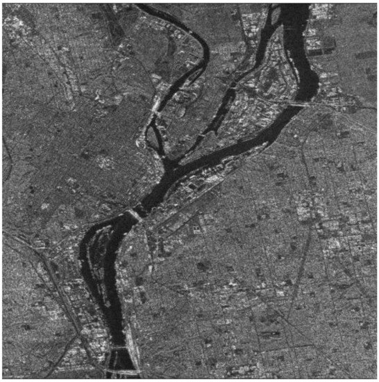
Figure 5.
Original SAR image.
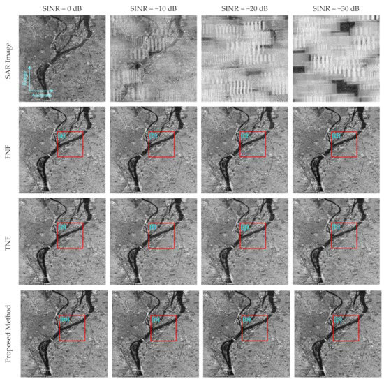
Figure 6.
RFI mitigation performance for the FNF, TNF, and proposed method under different SINR conditions.
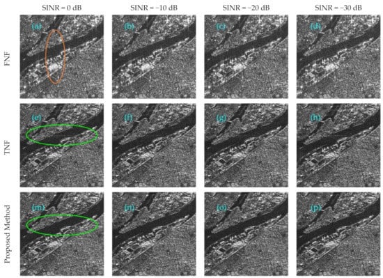
Figure 7.
ROIs in Figure 6. (a–d) Mitigation results for the FNF method. (e–h) Mitigation results for the TNF method. (m–p) Mitigation results for the proposed method.
We conducted quantitative analysis of the experimental results through RMSE. RMSE can be defined as:
According to Equation (43), we can see that RMSE represents the difference between the original SAR image and the results after RFI mitigation method processing. The smaller the RMSE, the better the effect of RFI mitigation. The RMSE results are shown in Table 2, where the proposed method had lower RMSE in the case of different SINR than the FNF method.

Table 2.
Evaluation metrics for the three methods in the case of different SINR.
4.2. Experimental Results of Measured Data
We use the level-0 raw data of Sentinel-1 IW mode to verify the effectiveness of the proposed method. The performance of the proposed method and FNF method was quantitatively analyzed by calculating the gray level entropy and average gradient in the measured data containing RFI with a single source or multiple sources.
Figure 8 shows the image of the measured Sentinel-1 data, which benefits from the Terrain Observation with Progressive Scans SAR (TOPSAR) technique, which can capture three sub-swaths at once. The data were acquired on 18 December 2021. As shown in Figure 8, the SAR image was seriously polluted by RFI. Two bursts with serious RFI were chosen for analysis, and the RFI-corrupted bursts are shown in Figure 8a,b.
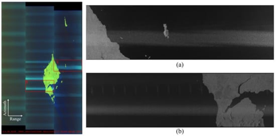
Figure 8.
SAR image of the measured Sentinel-1 data. (a) The RFI-corrupted burst with a single source. (b) The RFI-corrupted burst with multiple sources.
4.2.1. Experimental Results Based on Measure Data Contain RFI with Single Source
The image after AGC and the modified SBGFRLS model is shown in Figure 9, where the edge of the RFI signals was precisely segmented. The operation of image processing serves as the first layer of protection for useful signals without interference.

Figure 9.
The image after the modified SBGFRLS model in the case of RFI with a single source.
The three-dimensional diagram in the range-frequency and azimuth-time domain after FNF and the proposed method is shown in Figure 10, where (a) represents the RFI mitigation results by FNF, and (b) represents the RFI mitigation results by the proposed method. Compared with Figure 2a, FNF and the proposed method mitigated the RFI effectively. However, FNF failed to protect the useful signals with interference, and the signals of the inner part of the red line was set to zero. The proposed method not only mitigated the RFI, but also effectively protected the useful signals, which is conducive to the application of images.
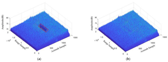
Figure 10.
The 3-dimensional diagram in the range-frequency and azimuth-time domain after RFI mitigation: (a) FNF; (b) the proposed method.
Figure 11 shows the RFI mitigation results for the SAR data containing RFI with a single source, (a–c) represents the RFI mitigation results for FNF, TNF, and the proposed method, respectively. It can be seen from Figure 11 that the image after processing by FNF had obvious loss of useful signals, and the image after processing by TNF still had some RFI. However, the proposed algorithm had the best RFI mitigation performance, and the protection capability for useful signals was the best.
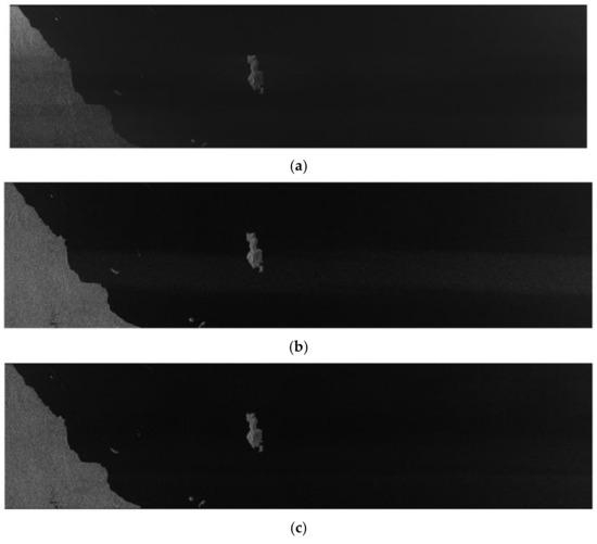
Figure 11.
The RFI mitigation results for the SAR data containing RFI with a single source: (a) FNF; (b) TNF; (c) the proposed method.
The mitigation performance of the proposed method was analyzed by the gray level entropy and average gradients.
The gray level entropy can be expressed as:
where represents the entropy of image; represents the total gray level; and represents the probability of the occurrence of a pixel with a gray value of . The average gradient can be expressed as:
where represents the position; represents the grayscale gradient in the vertical direction; and represents the grayscale gradient in the horizontal direction.
Through Equations (44) and (45), we could calculate the results. Then, the gray level entropy and average gradients were utilized to conduct quantitative analysis on the performance of different methods, and the advantages of the proposed method are shown in Table 3.

Table 3.
Gray level entropies and average gradients after FNF, TNF, and the proposed method (single source).
4.2.2. Experimental Results Based on Measurement Data Containing RFI with Multiple Sources
The image after AGC and the modified SBGFRLS model is shown in Figure 12. Although there was RFI with multiple sources in the image, the proposed method could still accurately extract the part of RFI, and the edge of the RFI signals was precisely segmented.

Figure 12.
The image after the modified SBGFRLS model in the case of RFI with multiple sources.
The 3-dimensional diagram in the case of RFI with multiple sources after FNF and the proposed method is shown in Figure 13, where (a) represents the RFI mitigation results by FNF, and (b) represents the RFI mitigation results by the proposed method. Compared with Figure 2b, although there were RFI with multiple sources, FNF and the proposed method mitigated the RFI effectively. However, FNF failed to protect the useful signals in the interference parts, and the signals of the inner parts of the red line were set to zero. The proposed method not only mitigated the RFI, but also effectively protected the useful signals, which was conducive to the application of images.
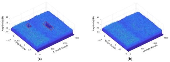
Figure 13.
The 3-dimensional diagram in the range-frequency and azimuth-time domain after RFI mitigation: (a) FNF; (b) the proposed method.
Figure 14 shows the RFI mitigation results for the SAR data containing RFI with multiple sources, (a–c) represents the RFI mitigation results for FNF, TNF, and the proposed method, respectively. It can be seen from Figure 14 that, in the case of RFI with multiple sources, the mitigation effect decreased, and the image after processing by FNF had obvious loss of useful signals. The image after processing by TNF had more RFI compared with (a). However, the proposed method still had a good inhibition effect. More importantly, Table 4 shows the gray level entropy and average gradients after mitigation by different methods, and it further proves the superiority of the proposed algorithm.
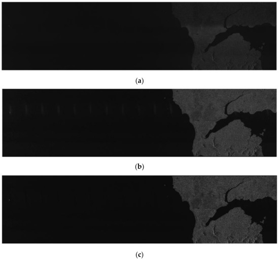
Figure 14.
The RFI mitigation results for the SAR data containing RFI with multiple sources: (a) FNF; (b)TNF; (c) the proposed method.

Table 4.
Gray level entropies and the average gradients after FNF, TNF, and the proposed method (multiple sources).
5. Discussion
It can be seen that the proposed method had the most protective and mitigation compared with the traditional methods from the experimental results. For the experimental results based on the simulated data, the performance of the proposed method was improved by about 20% compared with the FNF algorithm. For the experimental results based on the measurement data, on one hand, the RFI mitigation effect of the proposed method was better than other notch filtering methods, and the RFI in the SAR images was obviously mitigated. On the other hand, the proposed algorithm could effectively protect useful signals, and the image quality will not be affected after RFI mitigation, which is convenient for later application. Therefore, the above experiments show that the proposed method can effectively mitigate the RFI and protect the useful signals to the maximum extent, and it is not only applicable in the case of RFI with a single source, but also had a good effect in the case of RFI with multiple sources. The other method processed image still had some interference or ambiguity. This problem is caused by the interference signals that still exist or some useful signals are missing. In comparison, the proposed method was more similar with the original image, protecting the useful signal to the maximum extent and removing the interference signal. Therefore, in terms of the RFI mitigation effect, the proposed method has obvious advantages.
Regarding the computational efficiency, although the efficiency of the proposed algorithm had some losses compared with the FNF algorithm, the efficiency of the current image segmentation algorithms has been greatly improved in the present. The target area after segmentation was smaller, which is more conducive to further processing. Therefore, compared with the low-rank sparse decomposition algorithm, the processing time of the image after segmentation by the proposed method was more efficient.
6. Conclusions
This paper proposed a modified 2-D notch filter based on image segmentation for RFI mitigation. We were inspired by the idea of a traditional notch filtering method, then converted the raw data to the range-frequency and azimuth-time domain, and analyzed the characteristics of RFI first. Then, the AGC method was utilized in the field of image processing to enhance the image. After processing by AGC, the modified SBGFRLS model was utilized to segment the image, and part of RFI was separated from the image. The useful signals also existed in part of the RFI signals, therefore, the GSVT-based LRSD model was performed on the extracted part to screen out useful signals and the RFI signals, and restore the useful signals to the initial raw data at last. The simulation experiments and measured data experiments showed that the proposed method could effectively mitigate RFI and protect the useful signals, whether there was RFI with a single source or multiple sources. More importantly, the proposed method was superior to the traditional notch method.
However, the proposed method still has some limitations. For example, the calculation efficiency of the proposed algorithm is low compared with the traditional notch filtering methods. Therefore, the CPU parallelism or GPU will be used to improve the efficiency of the proposed method in the future, so the proposed method can be more suitable for some engineering application problems.
Author Contributions
Conceptualization, Z.F. and J.Z.; Data curation, Z.F.; Formal analysis, Z.F. and N.L.; Funding acquisition, J.Z. and N.L.; Investigation, H.Z. and N.L.; Methodology, Z.F. and N.L.; Project administration, F.Z., J.Z. and N.L.; Resources, N.L.; Software, F.Z., H.Z., Z.F. and J.Z.; Supervision, F.Z. and N.L.; Validation, F.Z., J.Z. and Z.F.; Visualization, Z.F.; Writing—original draft, Z.F. and N.L. All authors have read and agreed to the published version of the manuscript.
Funding
This work was supported in part by the National Natural Science Foundation of China under grants 61871175 and 41901302, and in part by the Foundation of Key Laboratory of Radar Imaging and Microwave Photonics, Ministry of Education under grant RIMP2020003.
Institutional Review Board Statement
Not applicable.
Informed Consent Statement
Not applicable.
Data Availability Statement
Not applicable.
Acknowledgments
The authors would like to thank the anonymous reviewers for their valuable and detailed comments that are crucial in improving the quality of this paper.
Conflicts of Interest
The authors declare no conflict of interest.
References
- Zhang, B.; Xu, G.; Zhou, R.; Zhang, H.; Hong, W. Multi-channel Back-projection Algorithm for mmWave Automotive MIMO SAR Imaging with Doppler-division Multiplexing. IEEE J. Sel. Top. Signal Process. 2022, 1–13. [Google Scholar] [CrossRef]
- Xu, G.; Zhang, B.; Yu, H.; Chen, J.; Xing, M.; Hong, W. Sparse Synthetic Aperture Radar Imaging from Compressed Sensing and Machine Learning: Theories, Applications and Trends. IEEE Geosci. Remote Sens. Mag. 2022, 2–40. [Google Scholar] [CrossRef]
- Reigber, A.; Scheiber, R.; Jager, M.; Prats-Iraola, P.; Hajnsek, I.; Jagdhuber, T.; Papathanassiou, K.P.; Nannini, M.; Aguilera, E.; Baumgartner, S. Very-High-Resolution Airborne Synthetic Aperture Radar Imaging: Signal Processing and Applications. Proc. IEEE 2013, 101, 759–783. [Google Scholar] [CrossRef]
- Peng, B.; Peng, B.; Zhou, J.; Xie, J.; Liu, L. Scattering Model Guided Adversarial Examples for SAR Target Recognition: Attack and Defense. IEEE Trans. Geosci. Remote Sens. 2022, 60, 5236217. [Google Scholar] [CrossRef]
- Peng, B.; Peng, B.; Zhou, J.; Xia, J.; Liu, L. Speckle-Variant Attack: Toward Transferable Adversarial Attack to SAR Target Recognition. IEEE Geosci. Remote Sens. Lett. 2022, 19, 4509805. [Google Scholar] [CrossRef]
- Moreira, A.; Prats-Iraola, P.; Younis, M.; Krieger, G.; Hajnsek, I.; Papathanassiou, K.P. A tutorial on Synthetic Aperture Radar. IEEE Geosci. Remote Sens. Mag. 2013, 1, 6–43. [Google Scholar] [CrossRef]
- Deng, Y.; Yu, W.; Zhang, H.; Wang, W.; Liu, D.; Wang, R. Forthcoming Spaceborne SAR Development. J. Radars 2020, 9, 1. [Google Scholar]
- Zhou, F.; Tao, M. Research on Methods for Narrow-Band Interference Suppression in Synthetic Aperture Radar Data. IEEE J. Sel. Top. Appl. Earth Obs. Remote Sens. 2015, 8, 3476–3485. [Google Scholar] [CrossRef]
- Li, N.; Lv, Z.; Guo, Z. Observation and Mitigation of Mutual RFI Between SAR Satellites: A Case Study Between Chinese GaoFen-3 and European Sentinel-1A. IEEE Trans. Geosci. Remote Sens. 2022, 60, 5112819. [Google Scholar] [CrossRef]
- Li, N.; Lv, Z.; Guo, Z. Pulse RFI Mitigation in Synthetic Aperture Radar Data via a Three-Step Approach: Location, Notch, and Recovery. IEEE Trans. Geosci. Remote Sens. 2022, 60, 5225617. [Google Scholar] [CrossRef]
- Lv, Z.; Zhang, H.; Li, N.; Guo, Z. A Two-Step Approach for Pulse RFI Detection in SAR Data. In Proceedings of the 2021 IEEE Sensors, Sydney, Australia, 3 October–3 November 2021; pp. 1–4. [Google Scholar]
- Lv, Z.; Li, N.; Guo, Z.; Zhao, J. Detection and Mitigation of Mutual RFI in C-band SAR: A Case Study of Chinese GaoFen-3. In Proceedings of the 2021 IEEE Radar Conference (RadarConf21), Atlanta, GA, USA, 7–14 May 2021; pp. 1–5. [Google Scholar]
- Su, J.; Tao, H.; Tao, M.; Wang, L.; Xie, J. Narrow-band Interference Suppression via RPCA-Based Signal Separation in Time–Frequency Domain. IEEE J. Sel. Top. Appl. Earth Obs. Remote Sens. 2017, 10, 5016–5025. [Google Scholar] [CrossRef]
- Chen, B.; Lv, Z.; Lu, P.; Shu, G.; Huang, Y.; Li, N. Extension and Evaluation of SSC for Removing Wideband RFI in SLC SAR Images. Remote Sens. 2022, 14, 4294. [Google Scholar] [CrossRef]
- Han, W.; Bai, X.; Fan, W.; Wang, L.; Zhou, F. Wideband Interference Suppression for SAR via Instantaneous Frequency Estimation and Regularized Time-Frequency Filtering. IEEE Trans. Geosci. Remote Sens. 2022, 60, 5208612. [Google Scholar] [CrossRef]
- Huang, Y.; Wen, C.; Chen, Z.; Chen, J.; Liu, Y.; Li, J.; Hong, W. HRWS SAR Narrowband Interference Mitigation Using Low-Rank Recovery and Image-Domain Sparse Regularization. IEEE Trans. Geosci. Remote Sens. 2022, 60, 5217924. [Google Scholar] [CrossRef]
- Huang, Y.; Liao, G.; Li, J.; Xu, J. Narrowband RFI suppression for SAR system via fast implementation of joint sparsity and low-rank property. IEEE Trans. Geosci. Remote Sens. 2018, 56, 2748–2761. [Google Scholar] [CrossRef]
- Huang, Y.; Liao, G.; Xiang, Y.; Zhang, Z.; Li, J.; Nehorai, A. Reweighted nuclear norm and reweighted Frobenius norm minimizations for narrowband RFI suppression on SAR system. IEEE Trans. Geosci. Remote Sens. 2019, 57, 5949–5962. [Google Scholar] [CrossRef]
- Huang, Y.; Liao, G.; Zhang, Z.; Xiang, Y.; Li, J.; Nehorai, A. Fast narrowband RFI suppression algorithms for SAR systems via matrix-factorization techniques. IEEE Trans. Geosci. Remote Sens. 2019, 57, 250–262. [Google Scholar] [CrossRef]
- Huang, Y.; Liao, G.; Zhang, L.; Xiang, Y.; Li, J.; Nehorai, A. Efficient narrowband RFI mitigation algorithms for SAR systems with reweighted tensor structures. IEEE Trans. Geosci. Remote Sens. 2019, 57, 9396–9409. [Google Scholar] [CrossRef]
- Huang, Y.; Liao, G.; Xu, J.; Li, J. Narrowband RFI suppression for SAR system via efficient parameter-free decomposition algorithm. IEEE Trans. Geosci. Remote Sens. 2018, 56, 3311–3322. [Google Scholar] [CrossRef]
- Zhang, H.; Huang, Y.; Li, J.; Chen, Z.; Cai, L.; Hong, W. Time-Varying RFI Mitigation for SAR Systems via Graph Laplacian Clustering Techniques. IEEE Geosci. Remote Sens. Lett. 2022, 60, 4010805. [Google Scholar] [CrossRef]
- Braunstein, M.; Ralston, J.; Sparrow, D. Signal Processing Approaches to Radio Frequency Interference (RFI) Suppression. In Proceedings of the SPIE 2230, Algorithms for Synthetic Aperture Radar Imagery, Orlando, FL, USA, 9 June 1994; pp. 190–208. [Google Scholar]
- Zhang, S.; Xing, M.; Guo, R.; Zhang, L.; Bao, Z. Interference Suppression Algorithm for SAR Based on Time-Frequency Transform. IEEE Trans. Geosci. Remote Sens. 2011, 49, 3675–3779. [Google Scholar] [CrossRef]
- Yang, H.; He, Y.; Du, Y.; Zhang, T.; Yin, J.; Yang, J. Two-Dimensional Spectral Analysis Filter for Removal of LFM Radar Interference in Spaceborne SAR Imagery. IEEE Trans. Geosci. Remote Sens. 2022, 60, 1–16. [Google Scholar] [CrossRef]
- Fan, W.; Zhou, F.; Rong, P.; Yao, X. Interference Mitigation for Synthetic Aperture Radar Using Deep Learning. In Proceedings of the Asia-Pacific Conference on Synthetic Aperture Radar, Xiamen, China, 26–29 November 2019; pp. 1–6. [Google Scholar]
- Lu, X.; Su, W.; Yang, J.; Gu, H.; Zhang, H.; Yu, W.; Yeo, T. Radio Frequency Interference Suppression for SAR via Block Sparse Bayesian Learning. IEEE J. Sel. Top. Appl. Earth Obs. Remote Sens. 2018, 11, 4835–4847. [Google Scholar] [CrossRef]
- Zhou, F.; Xing, M.; Bao, Z. Narrow Band Interference Suppression for SAR Using Eigen-Subspace Based Filtering. J. Electron. Inf. Technol. 2005, 27, 767–770. [Google Scholar]
- Zhou, F.; Tao, M.; Bai, X.; Liu, J. Narrowband interference suppression for SAR based on independent component analysis. IEEE Trans. Geosci. Remote Sens. 2013, 51, 4952–4960. [Google Scholar] [CrossRef]
- Zhou, F.; Xing, M.; Bai, X.; Sun, G.; Bao, Z. Narrowband interference suppression for SAR based on complex empirical mode decomposition. IEEE Geosci. Remote Sens. Lett. 2009, 6, 423–427. [Google Scholar] [CrossRef]
- Tao, M.; Zhou, F.; Liu, J.; Liu, Y.; Zhang, Z.; Bao, Z. Narrow-band interference mitigation for SAR using independent subspace analysis. IEEE Trans. Geosci. Remote Sens. 2014, 52, 5289–5301. [Google Scholar]
- Yang, H.; Li, K.; Li, J.; Du, Y.; Yang, J. BSF: Block Subspace Filter for Removing Narrowband and Wideband Radio Interference Artifacts in Single-Look Complex SAR Images. IEEE Trans. Geosci. Remote Sens. 2022, 60, 5211916. [Google Scholar] [CrossRef]
- Zhang, H.; Min, L.; Lu, J.; Chang, J.; Guo, Z.; Li, N. An Improved RFI Mitigation Approach for SAR Based on Low-Rank Sparse Decomposition: From the Perspective of Useful Signal Protection. Remote Sens. 2022, 14, 3278. [Google Scholar] [CrossRef]
- Shang, R.; Lin, J.; Jiao, L.; Li, Y. SAR Image Segmentation Using Region Smoothing and Label Correction. Remote Sens. 2020, 12, 803. [Google Scholar] [CrossRef]
- Nguyen, L.H.; Tran, T.D. Efficient and Robust RFI Extraction Via Sparse Recovery. IEEE J. Sel. Top. Appl. Earth Obs. Remote Sens. 2016, 9, 2104–2117. [Google Scholar] [CrossRef]
- Liu, H.; Li, D. RFI Suppression Based on Sparse Frequency Estimation for SAR Imaging. IEEE Geosci. Remote Sens. Lett. 2016, 13, 63–67. [Google Scholar] [CrossRef]
- Ding, Y.; Fan, W.; Zhang, Z.; Zhou, F.; Lu, B. Radio Frequency Interference Mitigation for Synthetic Aperture Radar Based on the Time-Frequency Constraint Joint Low-Rank and Sparsity Properties. Remote Sens. 2022, 14, 775. [Google Scholar] [CrossRef]
- Xu, W.; Xing, W.; Fang, C.; Huang, P.; Tan, W. RFI Suppression Based on Linear Prediction in Synthetic Aperture Radar Data. IEEE Geosci. Remote Sens. Lett. 2021, 18, 2127–2131. [Google Scholar] [CrossRef]
- Cazzaniga, G.; Guarnieri, A. Removing RF Interferences from P-band Airplane SAR Data. In Proceedings of the 1996 International Geoscience and Remote Sensing Symposium, Lincoln, NE, USA, 31 May 1996; pp. 1845–1847. [Google Scholar]
- Buckreuss, S.; Horn, R. E-SAR P-band SAR Subsystem Design and RF-interference Suppression. In Proceedings of the 1998 IEEE International Geoscience and Remote Sensing Symposium, Seattle, WA, USA, 6–10 July 1998; pp. 466–468. [Google Scholar]
- Meyer, F.; Nicoll, J.; Doulgeris, A. Correction and Characterization of Radio Frequency Interference Signatures in L-band Synthetic Aperture Radar Data. IEEE Trans. Geosci. Remote Sens. 2013, 51, 4961–4972. [Google Scholar] [CrossRef]
- Koitsoudis, T.; Lovas, L. RF interference suppression in ultrawideband radar receivers. In Proceedings of the Spies Symposium on Oe/aerospace Sensing and Dual Use Photonics, Orlando, FL, USA, 5 June 1995; Volume 2487, pp. 107–118. [Google Scholar]
- Le, C.; Hensley, S.; Chapin, E. Removal of RFI in wideband radars. International Geoscience and Remote Sensing Symposium. In Proceedings of the IEEE International Geoscience and Remote Sensing Symposium, Seattle, WA, USA, 6–10 July 1998; pp. 2032–2034. [Google Scholar]
- Le, C.; Hensley, S.; Chapin, E. Adaptive filtering of RFI in wideband SAR signals. In Proceedings of the 7th Annual JPL AirSAR Workshop, Pasadena, CA, USA; 1998; pp. 41–50. [Google Scholar]
- Potsis, A.; Reigber, A.; Papathanassiou, K. A phase preserving method for RF interference suppression in P-band synthetic aperture radar interferometric data. In Proceedings of the IEEE 1999 International Geoscience and Remote Sensing Symposium, Hamburg, Germany, 28 June–2 July 1999; pp. 2655–2657. [Google Scholar]
- Luo, X.; Ulander, L.; Askne, J.; Smith, G.; Frolind, P. RFI suppression in ultra-wideband SAR systems using LMS filters in frequency domain. Electron. Lett. 2001, 37, 241–243. [Google Scholar] [CrossRef]
- Harcke, L.; Le, C. AirMOSS P-band RF interference experience. In Proceedings of the IEEE Radar Conference, Cincinnati, OH, USA, 19–23 May 2014; pp. 761–764. [Google Scholar]
- Vu, V.; Sjögren, T.; Pettersson, M.; Håkansson, L.; Gustavsson, A.; Ulander, L. RFI suppression in ultrawideband SAR using an adaptive line enhancer. IEEE Geosci. Remote Sens. Lett. 2010, 7, 694–698. [Google Scholar] [CrossRef]
- Smith, T.; Hill, R.; Hayward, S.; Yates, G.; Blake, A. Filtering approaches for interference suppression in low-frequency SAR. IEE Proc. -Radar Sonar Navig. 2006, 153, 338–344. [Google Scholar] [CrossRef]
- ITU-R Recommendation RS. Mitigation Technique to Facilitate the Use of the 1215–1300 MHz Band by the Earth Exploration-satelite Service and the Space Research Service. Available online: https://www.itu.int/rec/R-REC-RS.1749/en (accessed on 2 November 2006).
- Nabil, H.; Chen, J.; Kamel, H. Bidirectional Notch Filter for Suppressing Pulse Modulated Radio-Frequency-Interference in SAR Data. In Proceedings of the 2014 IEEE International Geoscience and Remote Sensing Symposium, Quebec City, QC, Canada, 13–18 July 2014; pp. 1136–1139. [Google Scholar]
- Feng, J.; Zheng, H.; Deng, Y.; Gao, D. Application of Subband Spectral Cancellation for SAR Narrow-Band Interference Suppression. IEEE Geosci. Remote Sens. Lett. 2012, 9, 190–193. [Google Scholar] [CrossRef]
- Reigber, A.; Ferrofamil, L. Interference suppression in synthesized SAR images. IEEE Geosci. Remote Sens. Lett. 2005, 2, 45–49. [Google Scholar] [CrossRef]
- Doerry, A. Apodized RFI Filtering of Synthetic Aperture Radar Images. Available online: https://www.osti.gov/servlets/purl/1204095 (accessed on 17 January 2023).
- Natsuaki, R.; Motohka, T.; Watanabe, M.; Shimada, M.; Suzuki, S. An Autocorrelation-Based Radio Frequency Interference Detection and Removal Method in Azimuth-Frequency Domain for SAR Image. IEEE J. Sel. Top. Appl. Earth Obs. Remote Sens. 2017, 10, 5736–5751. [Google Scholar] [CrossRef]
- Li, N.; Lv, Z.; Guo, Z.; Zhao, J. Time-Domain Notch Filtering Method for Pulse RFI Mitigation in Synthetic Aperture Radar. IEEE Geosci. Remote Sens. Lett. 2021, 19, 1–5. [Google Scholar] [CrossRef]
- Wu, W.; Xiao, Y.; Lin, J.; Ma, L.; Khorasani, K. An Efficient Filter Bank Structure for Adaptive Notch Filtering and Applications. IEEE Trans. Audio Speech Lang. Process. 2021, 29, 3226–3241. [Google Scholar] [CrossRef]
- Huang, H.; Cheng, F.; Chiu, Y. Efficient Contrast Enhancement Using Adaptive Gamma Correction with Weighting Distribution. IEEE Trans. Image Process. 2013, 22, 1032–1041. [Google Scholar] [CrossRef]
- Kass, M.; Witkin, A.; Terzopoulous, D. Snakes: Active Contour Models. In Proceedings of the 1st International Conference on Computer Vision, London, UK, 1 October 1987; pp. 259–268. [Google Scholar]
- Liu, Y.; Ren, M.; Zhu, L.; Hu, X. Synthetic Aperture Radar Image Segmentation Method Based on Active Contour Model. Sci. Technol. Eng. 2019, 19, 221–227. [Google Scholar]
- Oveis, A.; Giusti, E.; Ghio, S.; Marco, M. Moving and Stationary Targets Separation in SAR Signal Domain Using Parallel Convolutional Autoencoders with RPCA Loss. In Proceedings of the IEEE Radar Conference, New York, NY, USA, 21–25 March 2022; pp. 1–6. [Google Scholar]
- Guo, Y.; Liao, G.; Li, J.; Chen, X. A Novel Moving Target Detection Method Based on RPCA for SAR Systems. IEEE Trans. Geosci. Remote Sens. 2020, 58, 6677–6690. [Google Scholar] [CrossRef]
- Yang, Z.; Fan, L.; Yang, Y.; Yang, Z.; Gui, G. Generalized Singular Value Thresholding Operator Based Nonconvex Low-rank and Sparse Decomposition for Moving Object Detection. J. Frankl. Inst. 2019, 356, 10138–10154. [Google Scholar] [CrossRef]
Disclaimer/Publisher’s Note: The statements, opinions and data contained in all publications are solely those of the individual author(s) and contributor(s) and not of MDPI and/or the editor(s). MDPI and/or the editor(s) disclaim responsibility for any injury to people or property resulting from any ideas, methods, instructions or products referred to in the content. |
© 2023 by the authors. Licensee MDPI, Basel, Switzerland. This article is an open access article distributed under the terms and conditions of the Creative Commons Attribution (CC BY) license (https://creativecommons.org/licenses/by/4.0/).