1. Introduction
Magnetic field observation from low earth orbit (LEO) satellites have become the main data source for geomagnetic field-related studies and global geomagnetic field modeling. There are quite a few LEO satellites equipped with science grade magnetometers, such as Ørsted [
1], CHAMP [
2], Swarm [
3], CSES [
4], etc. Among them, the latter two satellites are still operational which can provide both scalar and vector datasets. It should be pointed out that Swarm flies an optical bench with a star tracker on the boom to achieve precise alignment. The in-flight calibration is essential for scientific applications and thus requires checking or improving during nearly the whole lifetime of the mission.
The high precision magnetometer (HPM instrument [
5]) conducts the magnetic field measurements on the CSES. It includes two fluxgate magnetometers (FGM sensors to measure magnetic field vector) and one coupled dark state magnetometer (CDSM sensor [
6]), which is a scalar sensor measuring the strength of the magnetic field. All three sensors work together to provide magnetic field measurements from DC to ~15 Hz. Previous scientific studies have shown very good usability of the magnetometer data [
7,
8,
9]. In-flight calibration based on the CDSM’s scalar data is in principle well established and the quality is already very good. However, the calibration of the vector data, as we will introduce in the following, still has room for improvement.
Generally, for LEO satellites with both scalar and vector sensors, two key steps are needed for the FGM in-flight calibration: vector sensor intrinsic calibration and alignment between the orthogonalized magnetic field sensor and the reference coordinates of the star tracker [
10,
11,
12,
13]. The main purpose of the FGM intrinsic calibration is to estimate at least nine intrinsic model parameters (three offsets, three scale values and three non-orthogonality angles). Sometimes the number of parameters can exceed nine considering temperature, time dependent variation and other effects. Concerning alignment, the goal is to estimate the rotation of the vector field from the orthogonalized FGM sensor frame to the star sensor frame (described by three Euler angles). In the current CSES calibration scheme, offsets, scale values, non-orthogonality angles and Euler angles are calculated every day, and the dayside and nightside data are estimated separately [
14,
15] which means that we need to update two sets of model parameters every day. For comparison, these model parameters have had much longer updating periods for other missions such as Ørsted, CHAMP and Swarm. For the CSES, this brings a lot of calculations and thus inconvenience for routine data processing. Furthermore, the separate estimation of dayside and nightside parameters may cause unreal results. In addition, the model parameters vary in a way that it is nearly impossible to make an estimation when the CDSM is not operated correctly. Most importantly, we have found that the intensity difference between the CDSM and calibrated FGM shows a very clear seasonal variation. Finally, in specific scientific applications, e.g., when using magnetic field data from different satellites for geomagnetic field modeling, it is necessary to have consistent calibration methodology [
13] to avoid some unexpected errors.
In this work, we first try to improve the FGM intrinsic calibration by further considering the FGM sensor temperature correction and implement a longer-day calibration scheme. Based on these recalibrated datasets, Euler angles are then estimated along with global geomagnetic field modeling.
2. Scalar Calibration of FGM Intrinsic Parameters
The CSES FGM is considered to be a linear instrument, and
and
are the magnetic field vectors in orthogonal and non-orthogonal FGM sensor frame (both in the units of nT), respectively.
and
are related as follows [
10]:
where
is the offsets matrix in nT,
is the inverse of the scale value matrix, and
denotes to the inverse of the non-orthogonal matrix, with
.
The definition of (
,
,
) can be found in Figure 1 of Olsen et al. [
10]. Then, the scalar value calculated from FGM
can be written as:
In order to calculate the magnetic field vector in the orthogonal FGM frame of Equation (1), we need to solve nine model parameters
,
using the above relationship. In the current opened level 2 data calibration scheme [
14,
15], the scalar calibration of FGM data is regarded as a linear inverse problem by doing the square of Equation (3). Then, a least-squares (LS) approach is applied for the estimation of the model parameters. In this study, we will recalibrate data from a non-linear inverse way by using an iteratively linearized robust LS approach. First, let
be the predictions in Equation (3) when giving a set of model parameters
. Then, the LS solution of the model parameters for the
ith iteration is [
10]:
where
is the data residual field for the
ith iteration (
is the scalar intensity measured by CDSM), and
is the kernel matrix.
is the diagonal data weight matrix. Huber weights [
16] are used here and will be iteratively updated with the model parameters according to
.
denotes to a priori model and sets to (0, 0, 0, 1, 1, 1, 0, 0, 0) in our study.
is a diagonal matrix which is determined by the a priori value.
It should be pointed out that, before the above FGM calibration, CDSM data have finished their own calibration process (mainly heading error correction) and removed all interferences. The detailed method can be found in Section 2 of Zhou et al. [
14]. The interference includes magnetic disturbance from two FGM sensors and spacecrafts, which is 0-2nT and 0-3nT, respectively.
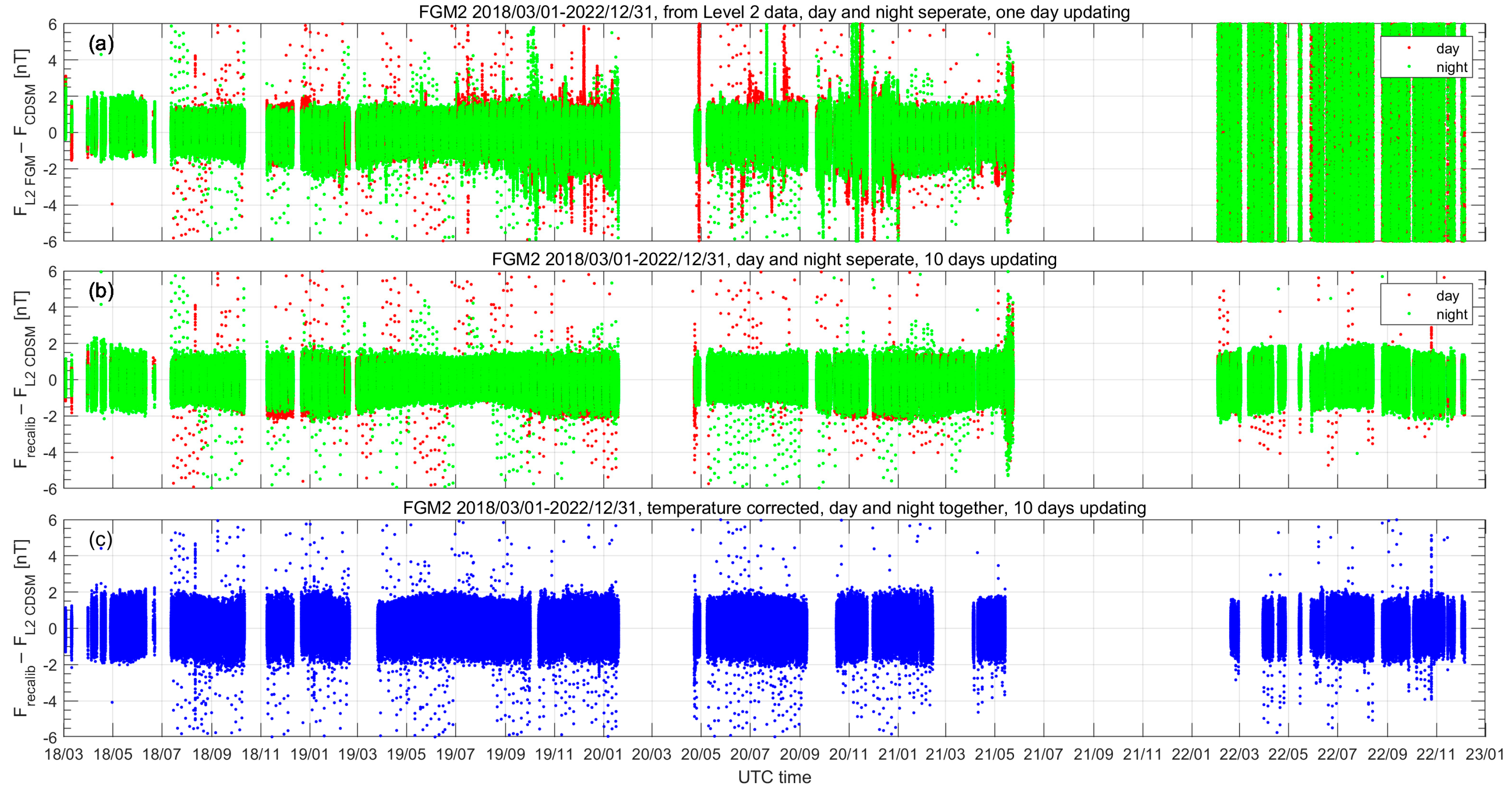
Figure 1a,b depict a validation of the methodology, via a comparison between the results from the established level 2 calibration (linear method) and the recalibrated data (non-linear method). Results are shown from March 2018 to December 2022. We use 1 min samples when doing the estimation to avoid overloading the computer. Before the calculation, the following abnormal datasets are excluded:
Datasets with magnetic field disturbance from magnetorquer and Tri-band Beacon (TBB); it should be noted that TBB operation has been stopped during the night since 13 January 2022 to avoid a disturbance of the magnetic field data measured by FGM.
Datasets where the electronic temperature () and FGM sensor temperature () exceed a certain limit: > 50 & < 40; < 5 & > 30.
Abnormal datasets from scalar intensity (both for CDSM and FGM), i.e., 15,000 < < 55,000, 15,000 < < 55,000.
To make a comparability study, the updated scheme from the current level 2 calibration with one day of updating and with dayside and nightside data separation was first applied to the new recalibration method. The results have shown a similar trend and values for the original and new method. Next, we tried to extend the updating period and finally found that 5 to 10 days of updating (with dayside and nightside data together) is completely suitable for the CSES (
Figure 1b). But for longer time periods (15 days for example), the magnetic field intensity residual shows clear non-sequential results. Based on this test phase, we have chosen a 10-day-long updating scheme for further processing. Theoretically, the above calibration parameters can be solved by using any period datasets. However, some problems may occur when trying a short period scheme. Actually, parameters are usually found to be unstable when we choose the previous one-day strategy. Sometimes, a bias parameter can even appear. In such situations, we had to identify and remove these abnormal parameters and then calibrate FGM data with the previous day’s parameter. Contrarily, the estimated parameters are relatively stable in the current longer time period and essentially, no bias values are found, thus providing more stable calibration results. So, scalar calibration generally requires a sufficient global and uniform coverage of the datasets. Since the revisiting period of the CSES is 5 days, the reasonable choice is at least 5 days, whereas for other missions like Swarm with drifting orbits (to cover all local times), longer periods are needed for a global coverage. From
Figure 1a,b, we can see that the result is very close for the two methods. Generally, the intensity residual is within ±2 nT, but sometimes it is also beyond this range. In
Figure 1a,b, a prominent seasonal trend can be observed. The residuals are larger between September and March of next year and smaller between April and August. This phenomenon hints that some effects are still not included in the current calibration scheme.
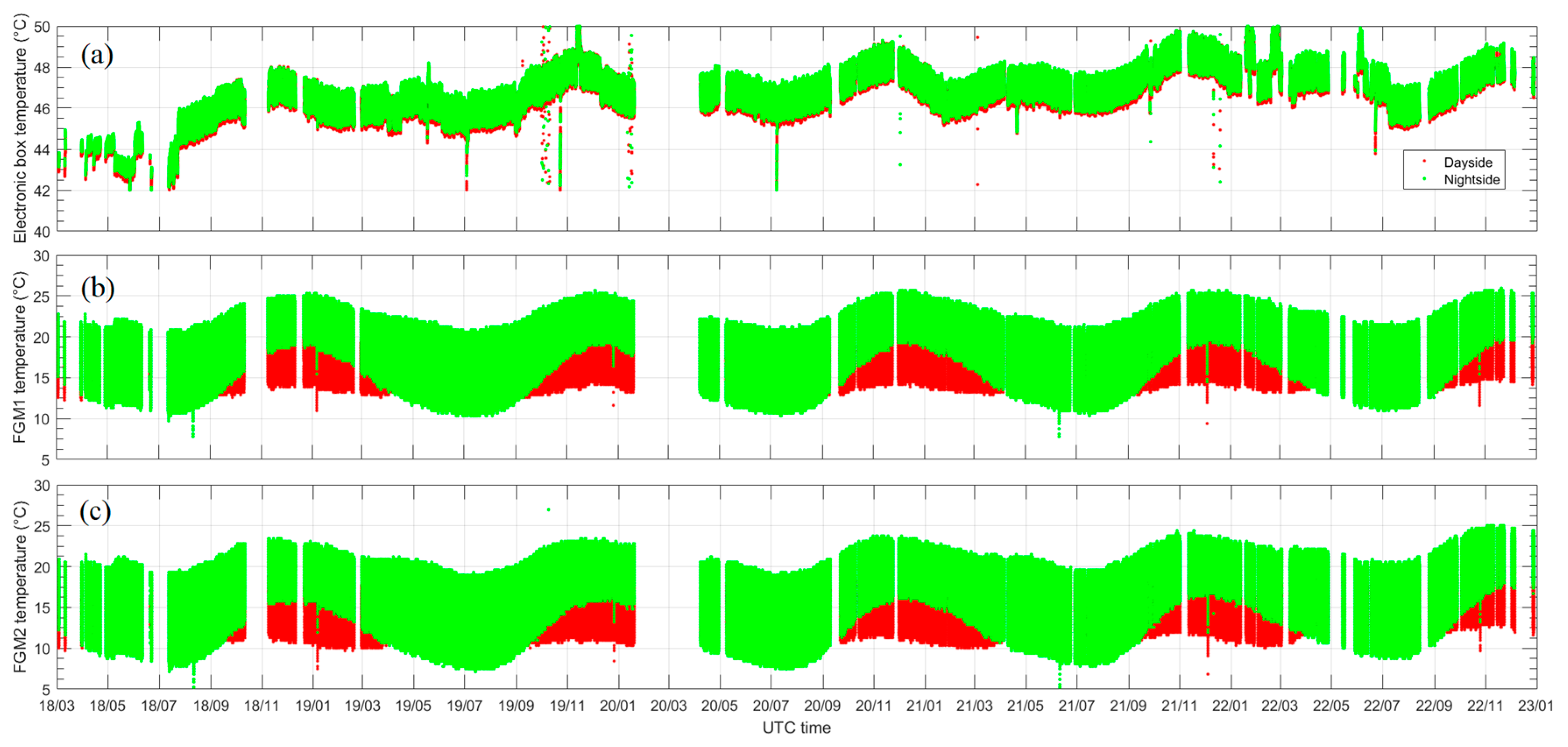
To further solve the seasonal trend observed in
Figure 1b, we first investigated the temperature variation of the electronic box and the two FGM sensors (see
Figure 2) and also found a similar seasonal trend. This feature was especially obvious on the FGM sensor temperature. Then, each temperature correction was separately tested on the offsets, scale factors and non-orthogonality. The result indicated that the joint temperature correction on the offsets and scale factors can help to improve the seasonal variation of the residual field (not shown here). So, a sensor temperature (
) correction has further been considered for the offsets and the scale factors:
In this configuration, 15 model parameters
,
have to be estimated. These model parameters are now updated every 10 days with dayside and nightside data together. The recalibrated results are shown in
Figure 1c with blue dots. Now, the intensity residual is stable and the seasonal variation has disappeared.
Figure 3 displays the time variation of the offsets (upper plot), scale values (middle plot) and non-orthogonality angles (lower plot) relative to the deviations from their mean values. The typical variation is ±2 nT for the offsets, less than 200 ppm (most of the time less than 100 ppm) for the scale values and ±0.0002 deg (about 0.7 arcsecs) for the non-orthogonality angles. In practice, we also tried a separate calibration for dayside and nightside datasets (not shown here). The result shows a smaller magnetic field intensity residual, but the typical value of the model parameters is larger, especially for non-orthogonality angles, with the largest value potentially even reaching ~100 arcsecs, which is obviously unreasonable according to our pre-flight test result. Therefore, the combined dayside and nightside strategy was finally chosen in our study.
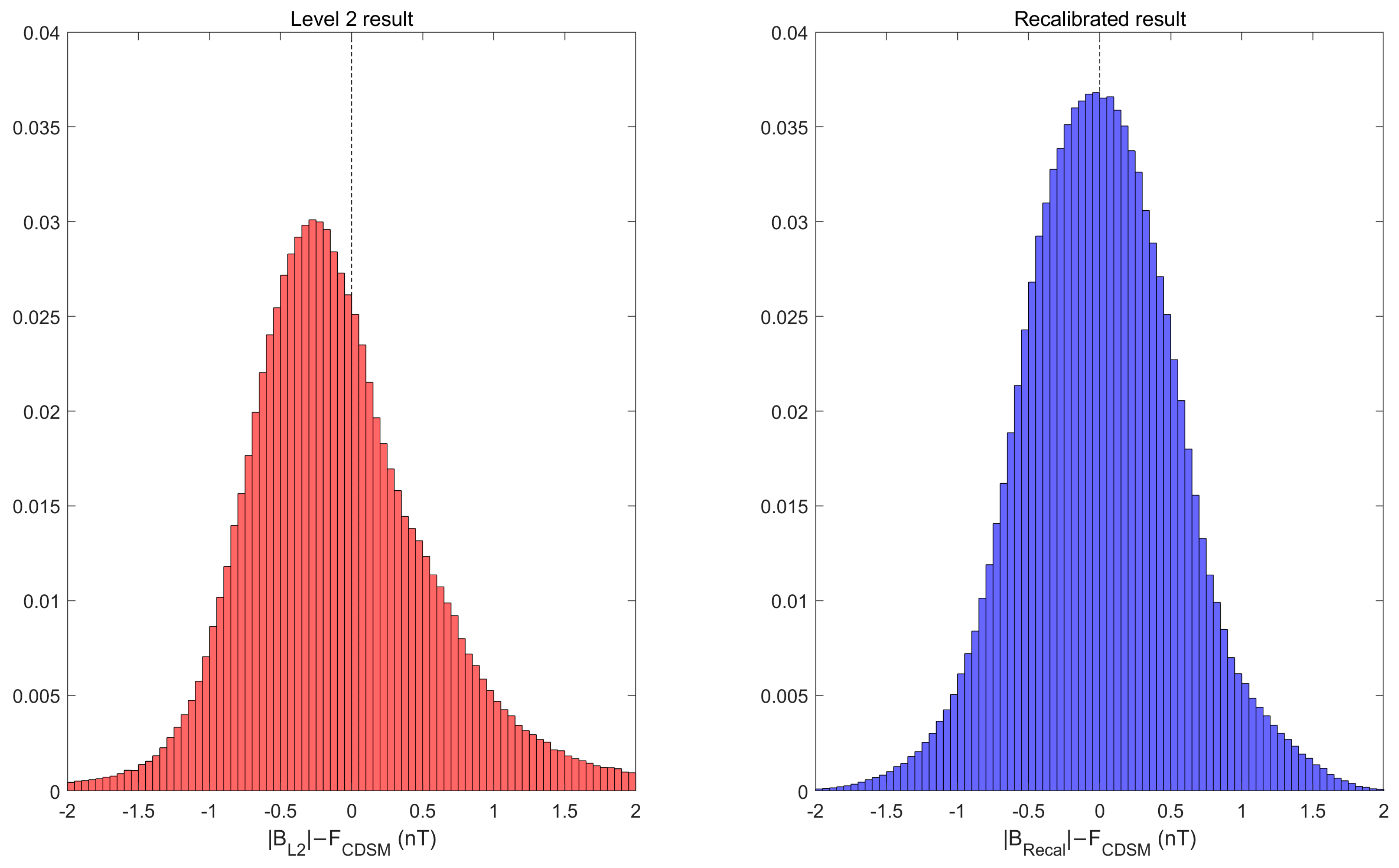
To make a more comprehensive comparison for the original level 2 dataset and our recalibrated (with the sensor temperature correction) dataset, the histograms of the residuals are plotted in
Figure 4. After the recalibration, the residuals adopt a more standard Gaussian distribution and become more centrally distributed. For about 93% of the datasets, the residual field is less than 1 nT.
3. Alignment of FGM
Figure 5 shows the coordinate transformation process from the CSES FGM orthogonal sensor frame
(i.e.,
) to the North-East-Center (NEC) frame. Four steps are included and thus the final magnetic field in the NEC frame
is calculated by:
where
are the transformation matrices for the rotation from the orthogonal FGM sensor coordinates to the star sensor (STR), to the Earth Centered Inertial (ECI, J2000 is used here) frame, to the Earth Centered Earth Fixed (ECEF) frame and finally to the North-East-Center (NEC) frame. These matrices are calculated with:
The first matrix on the right of Equation (7a) is used to rotate the orthogonal FGM frame into a “pseudo” SC coordinate system according to the installed principle of FGM (see Figure 2b of Cheng et al. [
5]). The calculation of
follows the method introduced in the International Earth Rotation and Reference Systems Service (
https://www.iers.org/IERS/EN/Publications/TechnicalNotes/tn36.html, accessed on 1 September 2023). Quaternions (
) are calculated by the three star sensors onboard the CSES. The transformation between spherical ECEF and NEC can be written as:
All parameters for the calculation of the transformation matrices in Equation 6 are known, except the alignment from the S/C frame to the STR coordinates. For this, three Euler angles (
,
,
) need to be calculated by a known
. Generally, there are two strategies to estimate the Euler angles: (a) using an existing model to provide a prediction of
and (b) defining the Euler angles as model parameters while simultaneously solving the spherical harmonics of a global geomagnetic field model [
10]. For the first method, the processing is simpler but depends on other geomagnetic field models, while in the second method, the processing is more complicated but the Euler angles are independently determined by their own datasets. In the work of Olsen et al. [
10], it has been proved that the calibration result from the two methods is similar. However, in some works, such as global geomagnetic field modeling, the second method is more favorable as it can unify the calibration process to diminish the possible error caused by a different calibration scheme, especially among different satellite missions.
In our previous data processing, we selected the first method, i.e., taking
from the CHAOS model, and then
,
and
could be estimated through Equation (7a) [
15]. In this scheme, similar with the estimation of
, the dayside and nightside Euler angles were also separately estimated and updated every day. From the perspective of processing efficiency (prolonging the updating period) and geomagnetic field modeling (e.g., combining other missions’ data in the future), this time we tried the second way by solving the Euler angles along with the Gauss coefficients of a geomagnetic field model. The data selection and methodology were completely the same with the CSES Global Geomagnetic field Model (CGGM model) and the Gauss coefficients were solved up to spherical harmonic degree and order 13 [
8]. In this method, the Euler angles were estimated every 10 days.
Figure 6 shows the time variation of the three Euler angles. We can see a relatively moderate variation and the value of the three Euler angles is small.
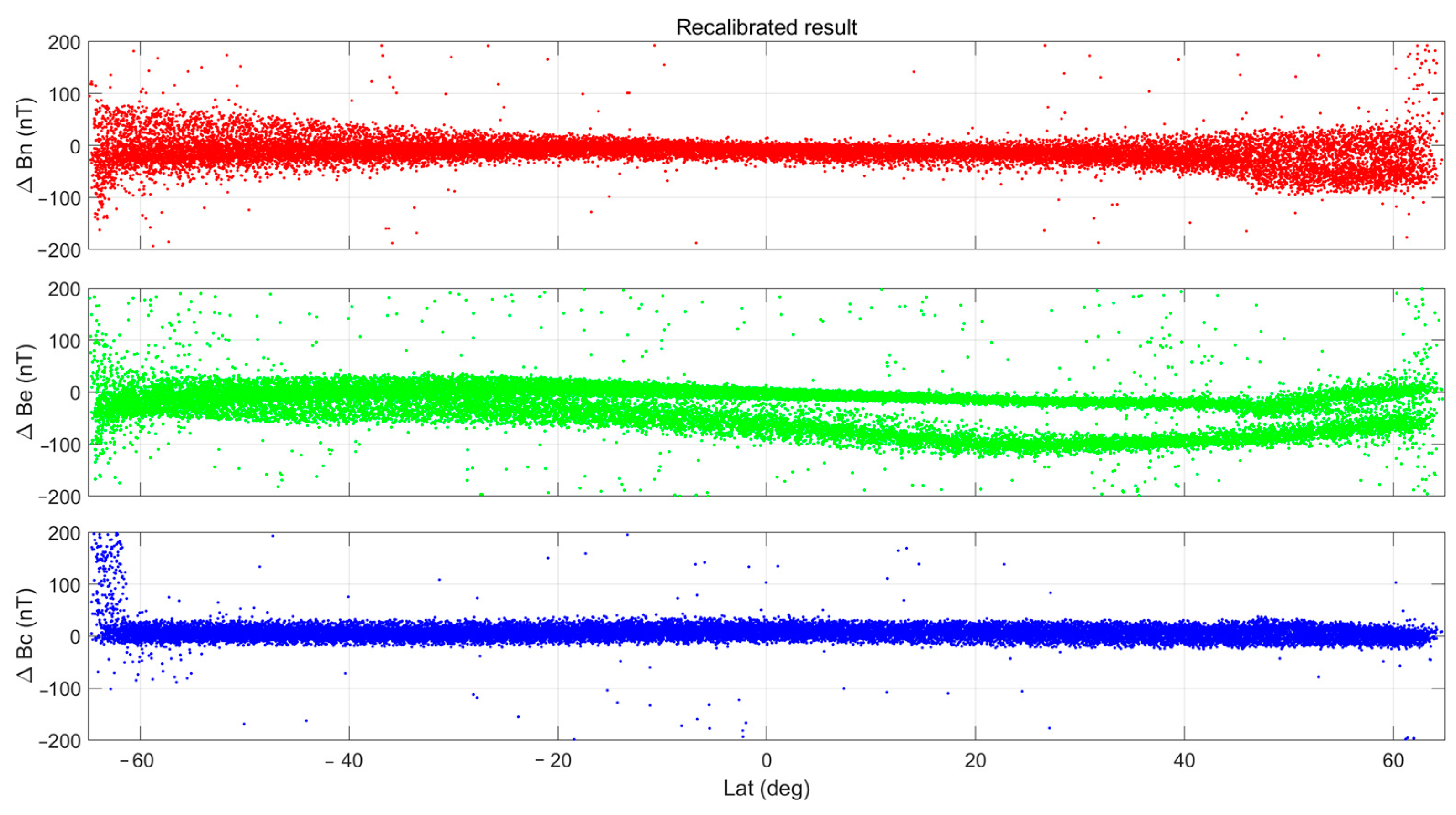
To further check the alignment result, the vector residual field between the CSES FGM and CHAOS model (in NEC frame) is calculated and plotted in
Figure 7. The left panels are from the level 2 results (the first scheme using the CHAOS model with the Euler angles updated every day and dayside and nightside data recorded separately) while the right panels come from the recalibrated methodology (the second scheme in which Euler angles are solved during a geomagnetic field modeling and with a 10-day updating period). The result is essentially very similar for the two methods. However, the level 2 results show more obvious latitudinal trends in the east component, i.e., a larger residual for higher latitude. In the new calibration scheme, the latitudinal trend for the east component is improved to some extent. Most importantly, the updating period of the Euler angles can extend from 1 day to 10 days now.
4. FGM In-Orbit Calibration without CDSM
Since the launch of the CSES, the CDSM has provided high-quality scalar magnetic field data which is essential for the in-orbit calibration of the FGM. However, two longer data gaps of the CDSM occurred due to operational problems. In order to keep the CSES spacecraft in its revisiting sun-synchronous orbit, orbital control maneuvers need to be performed every ~3 months (the time can be shorter during high geomagnetic activities). During these maneuvers, all payloads need to be turned off and then restarted again. The CDSM aboard the CSES requires a manual upload of certain instructions at a proper time and a certain location of the spacecraft. Thus, there are times which only have FGM data and CDSM data are missing. Specifically, at the beginning of 2020, a manual restart of the CDSM was not possible due to the COVID-19 pandemic which resulted in a more than 3-month-long scalar data gap from 19 January to 29 April 2020. From May 2021 to February 2022, the CDSM lost its microwave locking point due to a drift of the high frequency oscillator in the electronics. This resulted in an arbitrary drift of the scalar measurement from several nT to nearly 200 nT which cannot be corrected. In March 2022, fortunately, the CDSM was brought back to normal operation by adjusting the operational range of the oscillator.
With the new calibration scheme, which ensures the in-flight calibration model parameters update every 10 days, the calibration may not be affected if the CDSM data gap is just several days. For longer periods with missing scalar data from the CDSM, however, we need to find a way to calibrate FGM data. Our strategy is to make an interpolation for all missing model parameters (
,
,
,
), as shown by the star dots in
Figure 3 and
Figure 6. The interpolation method is chosen according to the time variation regulations of the model parameters. For the result shown here, shape-preserving piecewise cubic interpolation is performed for offsets, scale values and non-orthogonality angles and nearest neighbor interpolation is implemented for the three Euler angles. To validate the result, we again calculated the residual fields compared with the CHAOS model for the data gap from 19 January to 29 April 2020. The result (as shown in
Figure 8) is very similar to that which is presented in
Figure 7.
5. Conclusions
In this work, the processing scheme for the in-flight calibration of the fluxgate sensors aboard the CSES spacecraft was reworked based on data from March 2018 to December 2022. It included the recalibration of offsets, scale factors and non-orthogonality angles of the FGM sensor as well as the alignment angles which transform the orthogonalized coordinate system of the fluxgate sensors to the reference frame of the CSES’ star trackers. The new processing elements improve the processing efficiency as well as the in-orbit data quality in order to support more accurate scientific studies.
Four types of model parameters are estimated with the calibration scheme: offsets, scale values, non-orthogonality angles and alignment angles. In the processing flow so far, two sets of these parameters have been calculated every day since dayside and nightside data had to be estimated separately in order to obtain reasonably low residuals. Through this study, it is verified that the calibration result from a 10-day estimation scheme is suitable for the CSES FGM. So, we can prolong the model parameter updating cycle from the previous one day to 10 days, and this time only one set of model parameters needs to be calculated (for dayside and nightside data together) each time. Apart from the improvement in the calibration result, this will also help to improve HPM data processing efficiency. In the previous calibration, the time variation of the calibrated residual field, which is the difference between CDSM data and the field magnitude of the calibrated FGM, showed a clear seasonal effect. A comprehensive analysis indicated a similar trend on the sensor temperature, which drives us to further consider the sensor temperature correction on offsets and scale values. This study proves that the recalibrated result is a significant improvement and that the seasonal effect has disappeared.
Based on the recalibrated fluxgate sensor, we then carried out the alignment calibration to estimate the three Euler angles which are used to transform vector data from the FGM sensor coordinate system to star sensor frame. Euler angles are estimated along with global geomagnetic field modeling. Generally, the result showed a very similar trend with the previous one, but the latitudinal trend for the east component seems improved.
And last but not least, there will sometimes be no available CDSM data for the FGM in-orbit calibration. In such situations, it could be shown that all model parameters can be estimated by making an interpolation based on the other calculated parameters.
Due to the in-flight environment changing, such as the aging of the material and energetic particle radiation dose effects etc., longtime calibration is challenging. Therefore, in addition to regularly updating the parameters, it is necessary to check the payload operating parameters and carry out data validation through models (e.g., CHAOS), other satellite missions (such as Swarm) and ground observatories at the same time. Our future calibration strategy may be adjusted according to these calibration/validation results.


