Article

Joint Design of Complementary Sequence and Receiving Filter with High Doppler Tolerance for Simultaneously Polarimetric Radar

1
CAS Key Laboratory of Microwave Remote Sensing, National Space Science Center, Chinese Academy of Sciences, Beijing 100190, China
2
School of Electronic, Electrical, and Communication Engineering, University of Chinese Academy of Sciences, Beijing 100049, China
*
Author to whom correspondence should be addressed.
Remote Sens. 2023, 15(15), 3877; https://doi.org/10.3390/rs15153877
Submission received: 16 June 2023 / Revised: 29 July 2023 / Accepted: 31 July 2023 / Published: 4 August 2023
(This article belongs to the Special Issue Theory and Applications of MIMO Radar)

Abstract

:
Simultaneously polarimetric radar (SPR) realizes the rapid measurement of a target’s polarimetric scattering matrix by transmitting orthogonal radar waveforms of good ambiguity function (AF) properties and receiving their echoes via two orthogonal polarimetric channels at the same time, e.g., horizontal (H) and vertical (V) channels (antennas) sharing the same phase center. The orthogonality of the transmitted waveforms can be realized using low-correlated phase-coded sequences in the H and V channels. However, the Doppler tolerances of the waveforms composed by such coded sequences are usually quite low, and it is hard to meet the requirement of accurate measurement regarding moving targets. In this paper, a joint design approach for unimodular orthogonal complementary sequences along with the optimal receiving filter is proposed based on the majorization–minimization (MM) method via alternate iteration for obtaining simultaneously polarimetric waveforms (SPWs) of good orthogonality and of the desired AF. During design, the objective function used for minimizing the sum of the complementary integration sidelobe level (CISL) and the complementary integration isolation level (CIIL) is constructed under the mismatch constraint of signal-to-noise ratio (SNR) loss. Different SPW examples are given to show the superior performance of our design in comparison with other designs. Finally, practical experiments implemented with different SPWs are conducted to show our advantages more realistically.

Graphical Abstract

1. Introduction

Developments in radar technology have promoted the application of the polarimetric scattering information of targets, which can be characterized by the polarimetric scattering matrix (PSM) that connects the Jones vector of the incident wave with that of the scattering wave. The performance of radar on imaging, detection, and classification can be greatly improved by making full use of PSM in many fields, such as terrain observation, battlefield investigation, and disaster monitoring [1,2,3,4].
To accurately measure the PSM of moving targets, two typical fully polarimetric measurement schemes have been extensively investigated, i.e., the alternate polarimetric scheme and the simultaneously polarimetric scheme [5,6,7]. For the first scheme, the polarization state of the transmitted waveform is alternately switched between the vertical (V) and horizontal (H) polarizations, while both polarization states are received simultaneously. For high-speed targets, the two columns of the measured PSM can be decorrelated in the time domain and therefore the accuracy of the measurement results may be influenced. By contrast, for the second scheme, a pair of different waveforms of H and V polarization states are transmitted within one pulse simultaneously. As a result, the decorrelation impact can be avoided, but a stringent orthogonality requirement is put forward for the transmitted waveforms [6,7,8,9].
In addition to the orthogonality, low sidelobes of pulse compression in co-polarization channels are often required for weak target detection [10], i.e., good pulse compression characteristics of the waveforms are also desired for simultaneously polarimetric radar (SPR), as well as good orthogonality. Meanwhile, in the consideration of moving targets, the radar waveform should have good Doppler tolerance, i.e., it should be Doppler resilient [7,11]. These waveform properties can usually be evaluated by utilizing the ambiguity function (AF) [12,13]. Therefore, the AFs of ideal SPR waveforms must be of a two-dimensional “thumbtack” shape in co-polarization and an all-zero “plane” in cross-polarization channels, respectively [10,14].
Considering the nonlinear effects in practical hardware, it is preferable to make the waveform be of unimodular property, i.e., constant modulus [15,16,17]. In the early stage, a pair of linear frequency modulation (LFM) waveforms with opposite slopes are used to realize the simultaneously polarimetric measurement [5,18]. However, the peak sidelobe level (PSL) is just 13.26   d B after matched filtering. According to the principle of stationary phase, the orthogonality between the positive and negative slope LFM waveform is limited by the time–bandwidth product [19]. In recent years, phase-coded waveforms (PCWs) with good orthogonality are attractive for multichannel radar, such as SPR and MIMO (multiple-input–multiple-output) radar [7,20,21,22]. In [15,23], Stoica et al. proposed a series of cyclic algorithms for minimizing the integral sidelobe level (ISL) of unimodular waveforms, including cyclic algorithm-pruned (CAP), CA new (CAN), weighted CAN (We CAN), and CA direct (CAD). It is worth noting that Palomar et al. developed the majorization–minimization (MM) method to solve the nonconvex problem in unimodular sequence design by fast Fourier transform (FFT) [24,25]. This method is computationally attractive in the optimization of phase-coded sequences. Although many efforts have been put into the design of orthogonal PCWs with both low PSL and ISL. Nonetheless, it is impossible to obtain ideal correlation properties (ICPs), i.e., impulse-like autocorrelation and all-zero cross-correlation, for all the time delays using single pulse phase code, let alone the situation of various Doppler shifts [26,27,28].
The aforementioned difficulties motivate researchers to use the complete complementary sequence (CCS) in waveform design by taking advantage of the complementarity between CCS, which is a generalization of the well-known Golay code having been widely applied in the MIMO and CDMA communication systems because of its ICPs [29,30]. However, the ICPs will be seriously degraded even if a slight Doppler shift exists. This is the main obstacle to the wide application of CCS waveforms in radar [31]. In contrast to the waveform design suppressing the sidelobes of correlation functions, the waveform design minimizing the sidelobes of AFs can achieve the desired Doppler tolerance [12,32]. In [33], a construction method was proposed based on the Generalized Prouhet–Thue–Morse (GPTM) sequence by reordering the expanded version of an existing complementary sequence. The complementary properties can be kept over a modest Doppler frequency range (DFR). Nevertheless, the construction method has a strict limitation on the pulse number and code length of the complementary sequence. In [34], a set of almost complementary sequences was designed using the MM method. In their work, the pulse number and code length of CCS are no longer restricted, but there still is room to improve the Doppler tolerance. Recently, the limited-memory Broyden–Fletcher–Goldfarb–Shanno (L-BFGS) algorithm was used to optimize the AF of CCS [35,36,37]; however, the efficiency and the obtained optimal result still can be further improved.
The above studies mainly aim at the waveform design based on the matched filter scheme. It has been demonstrated that the pulse compression sidelobes can be suppressed effectively via mismatched filtering with a caveat of inducing an appropriate signal-to-noise ratio (SNR) loss [38,39,40]. In recent work, particularly [41,42], the joint design algorithm of the waveform and the receiving filter under the SNR loss constraint based on the MM method was reported with the purpose of minimizing the pulse compression sidelobes. However, for the SPR waveform, not only the low sidelobe of co-polarization channels but also the good orthogonality between cross-polarization channels and the Doppler tolerance should be considered simultaneously. Therefore, the applicability of these algorithms in the waveform design of SPR is limited.
In this paper, we focus on the joint design of orthogonal CCSs and receiving filters with desired Doppler tolerance for SPR waveforms. In addition, the main contributions can be summarized as follows:
(1)
Based on the AF, the joint design of unimodular orthogonal CCS (UOCCS) and receiving filter is proposed for SPR waveforms. Specifically, the complementary integrated sidelobe level (CISL) of Auto-AFs, the complementary integrated isolation level (CIIL) of Cross-AFs, and the mismatch constraint with controllable SNR loss are all considered simultaneously in the objective function formulated for optimization. By setting the predefined SNR loss, a trade-off between the suppression of CISL/CIIL and actual SNR loss can be achieved. In other words, the work in [41,42] was extended, i.e., the proposed scheme not only considers the low sidelobe of the pulse compression of CCS but also takes into account the orthogonality for all time delays within appropriate DFR.
(2)
The joint design problem is decomposed into subproblems of waveform design and receiving filter design via theoretical derivation, which is solved via an alternatively iterative approach. Concretely, the two subproblems are transformed into nonconvex quadratic terms containing the Hermitian matrix. The MM method is then applied to transforming these two nonconvex quadratic terms into linear programming problems with closed solutions. By utilizing the characteristics of Toeplitz matrix-vector multiplication, the main computation step can be completed via FFT. For further improvement, the convergence speed of the algorithm, an acceleration scheme of the squared iterative method (SQUAREM) is introduced. Compared with the representative and latest MM-CCS method [34] and the L-BFGS algorithm [35], better performance is achieved by the proposed algorithm, benefiting from both the joint design and the application of the MM framework.
The remainder of the paper is organized as follows. In Section 2, the problem of joint design CCSs and filters is formulated for the optimization of both the Auto-AFs and the Cross-AFs. In Section 3, the algorithm is developed with an acceleration scheme incorporated. In Section 4, several design examples are presented to show superior performance, and in Section 5, the designed waveforms using our method and that using the MM-CCS and the L-BFGS algorithm are implemented using an experimental hardware system, and extensive tests are conducted to demonstrate the actual performance. Finally, conclusions are drawn in Section 6.
Table 1 lists all used operators with explanations, and the bold lowercase and uppercase letters are used to denote the column vector of a matrix and a matrix throughout the paper.

2. Problem Statement

As we know, the unimodular constraint can avoid the nonlinear effect [43]. In the following, we first introduce two metrics, i.e., CISL and CIIL, for measuring the performance of the AFs of the unimodular waveforms. Then, the design problem is formulated as the objective function used for minimizing these two metrics under the constraint of controllable SNR loss.
Let us consider an SPR that transmits two orthogonal CCSs with H and V polarization, as shown in Figure 1a, and the signal-processing procedure at the radar receiver is shown in Figure 1b. In the transmitted signals of length N , each coherent processing interval (CPI) contains K pulses. In this case, the waveforms are diverse not only in different polarization states but also in different pulse-repetition intervals (PRIs).
Let us denote a pair of UOCCSs containing K pulses with length N in each pulse as [33]:
X H = x H 1 x H 2 x H K N × K
and
X V = x V 1 x V 2 x V K   N × K
where
x i k = x i k 1 x i k 2 x i k N T ,     x i k n = e j i k n ,   k = 1 , , K ,   i = H , V .
Let H H = h H 1 h H 2 h H K N × K , H V = h V 1 h V 2 h V K N × K denote the receiving filters, so, the discrete AF of sequence X i after filtered by H i ~ can be expressed as [33]:
A X i , H i ~ n , f = k = 1 K h i ~ k J n x i k e j 2 π k f
where
J n p , q = 1 ,   q p = n 0 ,   q p n     p , q = 1 , , N ,   n = N + 1 , , N 1 ,  
and f = f d T r is the normalized Doppler frequency, where f d and T r represent the nominal Doppler shift and PRI, respectively. When i = i ~ , (4) is the Auto-AF of X i ; otherwise, it is the Cross-AF. The key to designing high-Doppler-tolerance waveforms for SPR is to synthesize a pair of orthogonal CCS X H and X V with the desired AF properties within a certain DFR. In other words, our goal is to obtain the waveforms whose AFs are of low sidelobe and good orthogonality over a certain DFR.
The metrics CISL and CIIL should be considered when designing UOCCS for SPR waveforms, which are used to assess the performance of the Auto- and Cross-AF, respectively. The CISL and CIIL for a pair of orthogonal CCSs are defined by
C I S L X i , H i = n = 1 N , n 0 N 1 f 1 f 2 k = 1 K h i k J n x i k e j 2 π k f 2 d f
and
C I I L X i , H i ~ = n = 1 N N 1 f 1 f 2 k = 1 K h i ~ k J n x i k e j 2 π k f 2 d f , i i ~
where f 1 , f 2 denotes the interested DFR.
Compared with the matched filtering, the receiving filter in the mismatched scheme is no longer the conjugated and reversed transmitted waveform. In this case, the SNR loss caused by mismatch filtering is inevitable, and the SNR loss of two co-polarization channels of the SPR can be written as [44]
S N R L i = 10 l o g 10 k = 1 K x i k 2 k = 1 K h i k 2 k = 1 K h i k x i k 2
As shown in (8), the SNR loss is related to the peak values of pulse compression, the energy of the sequences, and the receiving filters. According to (3), the sequences satisfy unimodular constraint, so k = 1 K x i k 2 = K N . For the purpose of normalization, we assume the receiving filters have a constraint of k = 1 K h i k 2 = K N , the S N R L i can be constrained by a cost function
g X i , H i = k = 1 K h i k x i k a m a x 2
where a m a x is the predefined peak value of pulse compression. To guarantee an expected SNR loss μ (in dB), the predefined a m a x can be formulated as a m a x = K N 10 μ / 20 .
Thus, based on the Pareto weighting [45], the joint design problem under the mismatch constraint can be formulated as
min X , H C N × K Γ X , H = ε C I S L X H , H H + C I I L X H , H V + C I I L X V , H H + C I S L X V , H V + 1 ε g X H , H H + g X V , H V s .   t .   k = 1 K h i k 2 = K N ,     x i k n = 1 ,   n = 1 , , N ,   k = 1 , , K , i = H , V
where ε is the Pareto weight used to balance the metrics and the cost functions.

3. Joint Design of UOCCS and Receiving Filters via MM Method

3.1. Reformulation of the Problem

In this section, we shall reformulate the design problem in (10) for ease of solution. Let us define auxiliary sequences u and v of length 2 L   ( L = K 2 N 1 ) as follows:
u = x H 1 T     0 N 1 T     x H K T     0 N 1 T     x V 1 T     0 N 1 T   x V K T     0 N 1 T T
and
v = h H 1 T     0 N 1 T     h H K T     0 N 1 T     h V 1 T     0 N 1 T   h V K T     0 N 1 T T
where u and v denote the transmitted CCSs and receiving filters, respectively. Then we have
u m = S m u ,   v m ~ = S m ~ v ,   m , m ~ = 1,2
where 1 and 2 represent H and V polarization, respectively, and S m is an L × 2 L block selection matrix defined as
S 1 = I L   0 L ,   S 2 = 0 L   I L
Equation (6) can be rewritten as
C I S L u m , v m = n = 1 L L 1 f 1 f 2 w 1 ( n , f ) v m T n D i a g a ( f ) u m 2 d f
where T n , n = 1 L , , L 1 denotes L × L Toeplitz shift matrix similar to Equation (5),
a f = e j 2 π f 1 N T     0 N 1 T   e j 2 π K f 1 N T     0 N 1 T T
and
w 1 n , f = 1 ,   1 n N 1 ,   f 1 f f 2 0 ,   e l s e .
Similarly, (7) can be rewritten as
C I I L u m , v m ~ = n = 1 L L 1 f 1 f 2 w 2 ( n , f ) v m ~ T n D i a g a ( f ) u m 2 d f , m m ~
where
w 2 n , f = 1 ,   n N 1 ,   f 1 f f 2 0 ,   e l s e .
The objective function in (10) can then be rewritten as
  Γ u , v = ε m = 1 2 n = 1 L L 1 f 1 f 2 w 1 n , f v m T n D i a g a f u m 2 d f + ε m = 1 2 m ~ = 1 m ~ m 2 n = 1 L L 1 f 1 f 2 w 2 ( n , f ) v m ~ T n D i a g a ( f ) u m 2 d f + 1 ε v 1 u 1 a m a x 2 + v 2 u 2 a m a x 2
In (20), the first term contains the Auto-AF integrated sidelobes of two sequences for H and V polarizations. The second term denotes the integration of the Cross-AFs. The third term accounts for the differences in the peak values by mismatch filtering and the predefined peak values. For the convenience of discussion, we discretize the Doppler interval f 1 ,   f 2 into Q bins evenly with the grid size Δ f = f 2 f 1 / Q 1 , and ignore the constant terms. Equation (20) can then be reformulated as
  Γ u , v = m = 1 2 m ~ = 1 2 n = 1 L L 1 q = 1 Q w m , m ~ n , f q v m ~ T n D i a g a f q u m 2 2 a m a x λ R e v 2 u 2 + R e v 1 u 1
where f q = f 1 + q 1 f , 1 q Q and λ = 1 ε / ε , and the weighting factor changes to
w m , m ~ n , f = w 1 n , f + λ ,   m = m ~ ,   n = 0 ,   a n d   f = 0 w 2 n , f ,   m m ~ w 1 n , f ,   e l s e
and
v m ~ T n D i a g a f q u m = T r T n P m m ~ q
where P m m ~ q = u m q v m ~ and u m q = D i a g a f q u m .
Since T r T n P m m ~ q = v e c P m m ~ q v e c T n , so the problem (10) can be finally formulated as
m i n u , v C 2 L × 1     Γ u , v = m = 1 2 m ~ = 1 2 q = 1 Q v e c P m m ~ q Q m m ~ q v e c P m m ~ q 2 a m a x λ R e v 2 u 2 + R e v 1 u 1 s .   t .   v m v m = K N ,   x k n = 1 ,   n = 1 , , N ,   k = 1 , , 2 K ,   m , m ~ = 1,2
where
Q m m ~ q = n = 1 L L 1 w m , m ~ n , f q v e c T n v e c T n

3.2. Joint Optimization via the MM Method

Due to the unimodular constraint, the optimization problem in (24) is nonconvex, so it cannot be straightforwardly used to solve for the transmitted sequence u and the receiving filter v at the same time. Thus, the alternately iterative scheme is introduced to transfer this complex problem (24) into two sub-optimization problems. In addition, for each subproblem, one variable is optimized while keeping the other variable fixed, which can be formulated as
v l = arg min v Γ u l 1 , v
u l = arg min u Γ u , v l
where v l and u l are the solutions to the two sub-optimization problems of (26a) and (26b) at the l th iteration, respectively.
Lemma 1 
[24]. Let both L and M denote an n × n Hermitian matrix such that M L . Then for any point x 0 C n , the quadratic function x L x can be majorized by x M x + 2 R e ( x   ( L M ) x 0 ) + x 0 ( M L ) x 0 at x 0 .
The proof of Lemma 1 was given in [24], and it is omitted here. One can see from (24) that the objective function is composed of a quadratic term of v e c P m m ~ q , and a Hermitian matrix Q m m ~ q . Thus, by applying Lemma 1 and selecting M = γ m a x Q m m ~ q I L 2 , we have
v e c P m m ~ q Q m m ~ q v e c P m m ~ q   v e c P m m ~ q γ m a x Q m m ~ q v e c P m m ~ q + 2 R e v e c P m m ~ q Q m m ~ q γ m a x Q m m ~ q I L 2   v e c P m m ~ q l + v e c P m m ~ q ( l ) γ m a x Q m m ~ q I L 2 Q m m ~ q   v e c P m m ~ q ( l )
where γ m a x Q m m ~ q is the maximum eigenvalue of Q m m ~ q , which has been deduced in detail in [24], and can be written as
γ m a x Q m m ~ q = max n N , , N w m , m ~ n , f q L n
Since the elements of u are of unimodular or zero and v v = K N , the first term of the right side of (27) is just a constant and it is true for the last term. After ignoring the constants, the optimization of (24) can be written as
m i n u , v C 2 L × 1     Γ u , v = m = 1 2 m ~ = 1 2 q = 1 Q 2 R e v e c P m m ~ q Q m m ~ q γ m a x Q m m ~ q I L 2   v e c P m m ~ q ( l ) 2 a m a x λ R e v 2 u 2 + R e v 1 u 1 s .   t .   v m v m = K N ,   x k n = 1 ,   n = 1 , , N ,   k = 1 , , 2 K ,   m , m ~ = 1,2
For subproblem (26a), it optimizes the receiving filter v under the condition of fixing CCS u . By substituting Q m m ~ q of (25) and P m m ~ q ( l ) = u m q v m ~ ( l ) back into (29), we have (detailed derivation is provided in Appendix A)
R e v e c P m m ~ q Q m m ~ q v e c P m m ~ q ( l ) = R e v m ~ R m m ~ l q u m q
where
R m m ~ l q = n = 1 L L 1 w m , m ~ n , f q A u m , v m ~ l n , f q * T n
and we have
R e v e c P m m ~ q γ m a x Q m m ~ q v e c P m m ~ q l = R e γ m a x Q m m ~ q v m ~ v m ~ l u m q u m q
The optimization in (29) is a linear program problem that is quadratically constrained, which can be readily solved using the Lagrange multiplier [46]. Therefore, the problem (26a) can be simplified as
m i n v C 2 L × 1     m ~ = 1 2 2 R e v m ~ y m ~ s .   t .   v m ~ v m ~ = K N ,   x k n = 1 ,   n = 1 , , N ,   k = 1 , , 2 K ,
where
y m ~ = m = 1 2 q = 1 Q R m m ~ l q u m q γ m a x Q m m ~ q ( N K ) v m ~ l a m a x λ u m ~
According to the constraint of k = 1 K h i k 2 = K N on receiving filters, the update of the optimal solution to receiving filter is given by
v m ~ l + 1 = K N y m ~ 2 y m ~
Then, for subproblem (26b), it optimizes the CCS u under the condition of fixing receiving filter v . By substituting Q m m ~ q of (25) and P m m ~ q ( l ) = u m q ( l ) v m ~ back into (29) again, we obtain
R e v e c P m m ~ q Q m m ~ q v e c P m m ~ q ( l ) = R e u m D i a g a f q R m l m ~ q v m ~
where
R m l m ~ q = n = 1 L L 1 w m , m ~ n , f q A u m ( l ) , v m ~ n , f q T n
and obtain
R e v e c P m m ~ q γ m a x Q m m ~ q v e c P m m ~ q l = R e u m D i a g a f q γ m a x Q m m ~ q N K u m q ( l )
Similarly, problem (26b) can be simplified as
m i n u C 2 L × 1     m = 1 2 2 R e u m z m s .   t .   v m v m = K N ,   x k n = 1 ,   n = 1 , , N ,   k = 1 , , 2 K
where
z m = m ~ = 1 2 q = 1 Q D i a g a f q R m l m ~ q v m ~ γ m a x Q m m ~ q N K u m q ( l ) a m a x λ v m
According to the unimodular constraint, the closed-form solution to CCS can be expressed as
u m l + 1 = e j a r g z m c
and
c = 1 N T     0 N 1 T     1 N T     0 N 1 T T
However, it should be noted that the matrices R m m ~ l q and R m l m ~ q are Hermitian Toeplitz, so the matrix-vector multiplication terms of R m m ~ l q u m q and R m l m ~ q v m ~ in (34) and (40) can be computed more efficiently via FFT. In the following, we introduce a simple conclusion regarding the Toeplitz matrices T .
Lemma 2 
[34]. Let  T denote an n × n Toeplitz matrix defined as follows:
T = t 0 t 1 t N 1 t 1 t 0 t 1 t 1 N t 1 t 0
and F is another 2 N × 2 N FFT matrix with F m , n = e j 2 m n π 2 N , 0 m , n 2 N . Then T can be decomposed as T = 1 2 N F : , 1 : N D i a g F c F : , 1 : N , where  c = t 0 , t 1 , , t 1 N , 0 , t N 1 , , t 1 T .
The detailed proof of Lemma 2 can be viewed in Appendix B of Reference [34]. By defining the first N columns of the 2 N × 2 N FFT matrix as an 2 N × N matrix H , according to Lemma 2, we have
R m m ~ l q = 1 2 N H D i a g F c m m ~ l q H
where
c m m ~ l q = w m , m ~ 0 , f q A u m , v m ~ ( l ) 0 , f q * ,   w m , m ~ 1 , f q A u m , v m ~ ( l ) 1 , f q * , , w m , m ~ 1 L , f q A u m , v m ~ l 1 L , f q * ,   0 , w m , m ~ L 1 , f q A u m , v m ~ l L 1 , f q * , , w m , m ~ 1 , f q A u m , v m ~ ( l ) , 1 , f q * T
Thus, the matrix-vector multiplication R m m ~ l q u m q in (34) can be efficiently calculated by
R m m ~ l q u m q = 1 2 N H D i a g F c m m ~ l q H u m q
Similarly, R m l m ~ q v m ~ in (40) can be calculated in the same fashion. Now, we are ready to summarize the algorithm for the joint design of the orthogonal CCSs and the receiving filters with a desired AF shape as Algorithm 1. Its computational complexity is of order O ( 4 Q K N l o g K N ) per iteration.
Algorithm 1. Joint Design CCSs and Receiving Filters with Expected AFs Shape Based on the MM Method via Alternately Iteration
Initialize: l = 0 , pulse number K , sequence and filter length N , a predefine SNR loss μ , the DFR as f 1 ,   f 2 .
1: Compute the predefined a m a x
2: Initialize u 0 , v 0 of length 2 L as (11) and (12)
3: compute γ m a x Q m m ~ q by (28)
4: repeat
5: Compute y m ~ by (34) with the designated u l
6: Update the receiving filters v 1 l + 1   and v 2 l + 1 by (35)
7: Compute z m by (40) with the designated v l + 1
8: Update the CCSs u 1 l + 1   and u 2 l + 1 by (41)
9: l = l + 1 ;
10: until convergence
Output: CCS u and receiving filter v with expected AFs.

3.3. Acceleration Scheme Using SQUAREM

The monotonicity of the optimization problem can be guaranteed by the MM method, but the convergence speed of which depends on the property of the majorization function. Generally speaking, the speed of the proposed algorithms is quite slow. Here, the SQUAREM is adopted to accelerate the optimization, which is based on the idea of the Cauchy–Barzilai–Borwein (CBB) [47], and it was originally applied to accelerating the Expectation-Maximization (EM) method [48]. For SQUAREM, it only requires the update rule of the optimization algorithm to be the same as the EM algorithm. Since the MM method is the generalization of the EM method, the update rules are all based on fixed-point iteration, so the SQUAREM scheme can be conveniently used to accelerate the convergence of the proposed algorithm after some minor modifications.
Based on the proposed Algorithm 1, let us denote the nonlinear fixed-point iteration map F M M · for minimizing Γ u , v as
x l + 1 = F M M x l
where x represents optimization variable u or v during using alternately iterative.
The iteration map F M M · of the proposed algorithm is given by (35) and (41). Then the SQUAREM scheme can be implemented as Algorithm 2. For the general SQUAREM, it should be pointed out that it may break the nonlinear constraints. Therefore, a projection transformation P x · is needed to project wayward points into the feasible domain in Algorithm 2. Considering two kinds of different constraints, i.e., the unimodular constraint on the sequences and the constraint of k = 1 K h i k 2 = K N on the receiving filter, the projection can be simply represented as P x · = e j a r g ( · ) for the first constraint, and as P x ( · ) = K N ( · ) 2 ( · ) for the second constraint. Another problem is that the general SQUAREM may break the monotonicity of the initial MM method. Thus, a strategy has been taken in Algorithm 2 based on backtracking: repeatedly halves the distance between α and 1 , i.e., α α 1 / 2 until the monotonicity is maintained, and in practice the monotonicity of the algorithm can be maintained by taking only a few backtracking steps.
Algorithm 2. The Acceleration Scheme for Algorithm 1 using SQUAREM.
1: Initialize: l = 0 , x ( 0 )
2: repeat
3: x 1 = F M M x l
4: x 2 = F M M x 1
5: y = x 1 x l
6: z = x 2 x 1 y
7: Compute the step-length α = y / z
8: x = P x x l 2 α y + α 2 z
9: while  f x > f ( x l ) do
10: α α 1 / 2
11: x = P x x l 2 α y + α 2 z
12: e n d w h i l e
13: x l + 1 = x
14: l l + 1
15: until convergence.

4. Simulations and Performance Analysis

In this section, simulations are carried out to show the effectiveness of the proposed algorithm and at the same time to investigate the effects of key parameters on the performance. The sequences and filters are initialized with randomly generated phase-coded sequences e j n uniformly distributed within 0,2 π . Meanwhile, since we try to optimize nonconvex problems, although the local minima of the objectives are approximately global [49], the difference in initial sequences has a slight effect on the performance of the algorithm. To guarantee the optimized result with the best performance, 100 Monte Carlo trials are carried out for all cases and the optimal solutions are obtained. For clarity, the accelerated algorithm for optimization problem (10), i.e., Algorithm 2, is denoted as MM-CSRF (MM-Complementary Sequence and Receiving Filter). All simulations are conducted using a PC equipped with a 3.0-GHz Intel Core i7-9700 CPU and 16-GB RAM along with MATLAB R2020a.

4.1. Performance of the Proposed Method

In this subsection, we define the metric complementary integrated AF level (CIAL) as the sum of C I S L X , H and C I I L X , H , and measure the performance of our algorithm and that of the L-BFGS algorithm [35] in minimizing the CIAL. For all cases, the transmitted CCS u ( 0 ) and receiving filter v ( 0 ) are initialized by independent random variables. The metric normalized CIAL (NCIAL) (in dB) at the i th iteration is defined as:
N C I A L ( i ) = 10 log 10 C I S L u ( i ) , v ( i ) + C I I L u ( i ) , v ( i ) C I S L u ( 0 ) , v ( 0 ) + C I I L u ( 0 ) , v ( 0 )
The bandwidth of the phase-codes waveform is approximately equal to 1 / t P , where t P is the subcode time duration [50]. If the code length is N, the pulse duration is then N t P . Therefore, the time–bandwidth product of a single pulse of the designed waveforms is equal to N . Hereafter, we assume that the code length of a single pulse in the designed waveforms and the filter are both N .
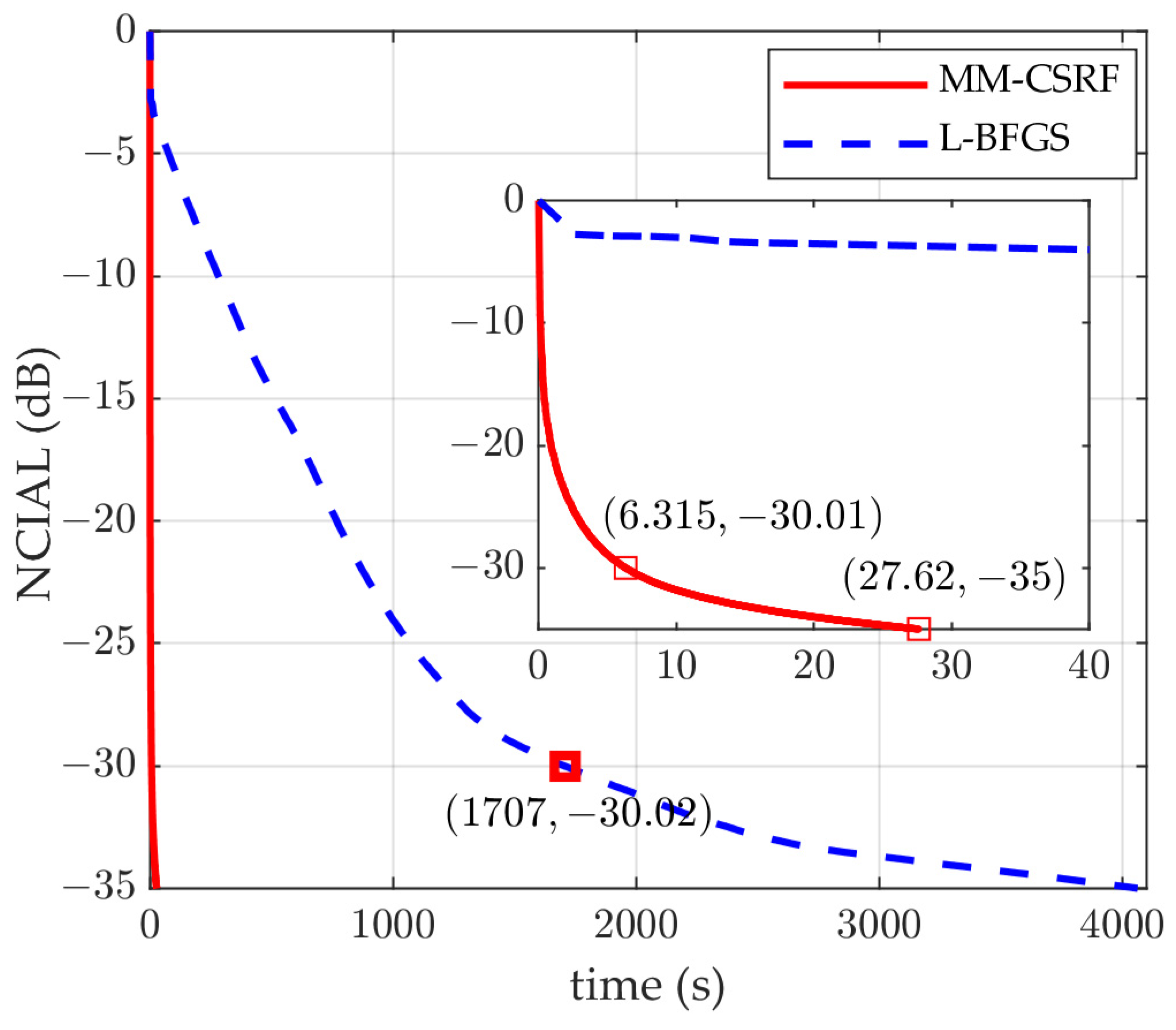
Example 1: In this example, we show the convergence performances of the MM-CSRF algorithm and that of the L-BFGS algorithm. Suppose N = 64 ,   K = 1 6, and the normalized DFR is f [ 0.2 ,   0.2 ] , which are the same as those in [35]. For the MM-CSRF algorithm, the weight factor is λ = 10 , and the predefined SNR loss is μ = 0.5   dB . For both algorithms, the iteration stops when the NCIAL in (47) is less than −35 dB or after 10,000 s of processing.
The evolutions of the NCIAL along with the running time are presented in Figure 2, from which we can observe that our algorithm exhibits significant superiority in the running time compared to the L-BFGS algorithm. More specifically, it takes only 27.62 s to drive the NCIAL close to 35   d B for our algorithm, while for the L-BFGS algorithm, it is still greater than 30   d B after 1700 s of runtime, and finally drives NCIAL to 35   d B after 4000 s. This is because the main steps are the computation of matrix-vector multiplication in the proposed algorithm, which can be completed via FFT using the characteristic of the Toeplitz matrix.
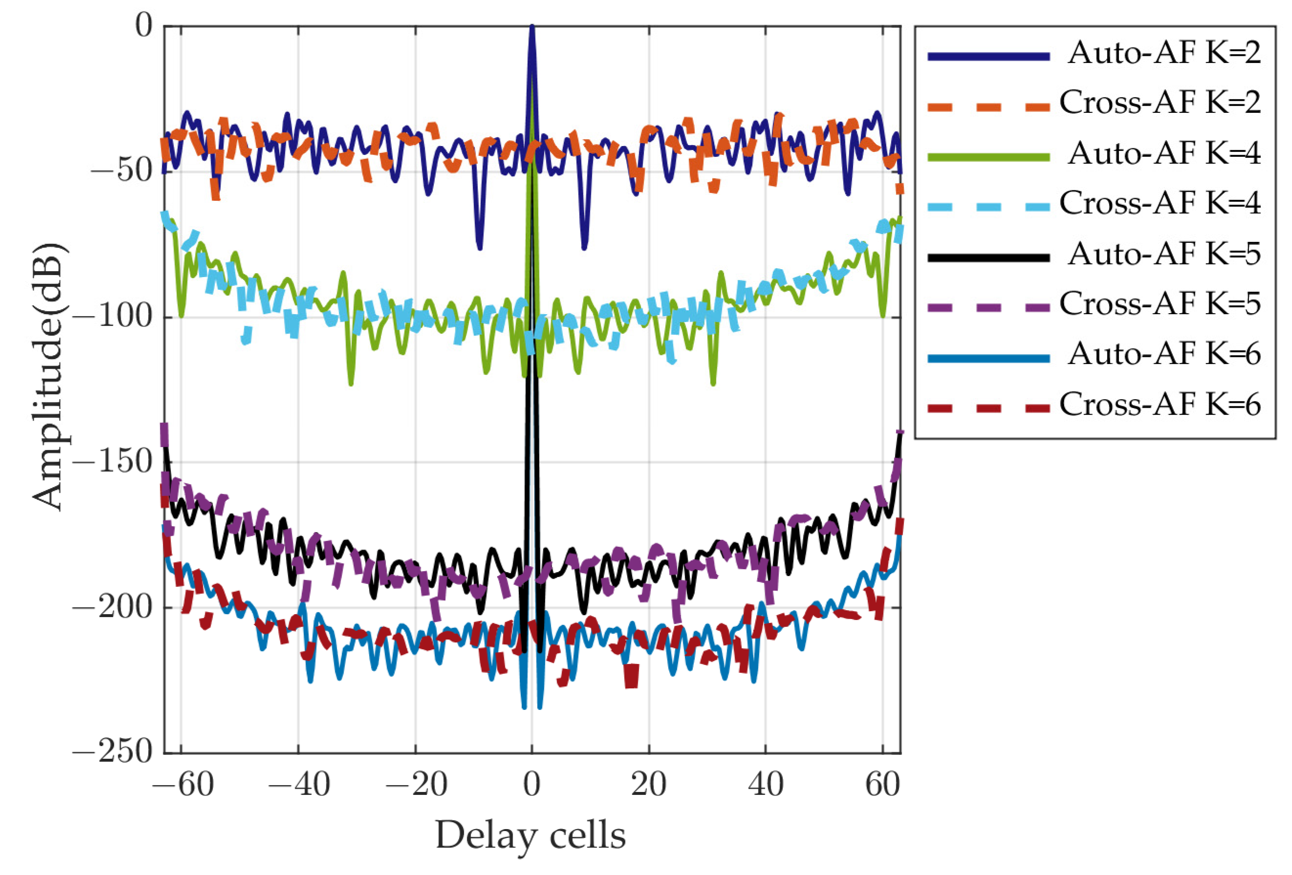
Example 2: In this example, the CCSs and receiving filters for zero-Doppler shift are designed by the MM-CSRF algorithm with N = 64 and without the SNR loss, i.e., μ = 0   d B , and the weight factor is λ = 10 . The processing stops after 10,000 iterations. A group of zero-Doppler cuts of the AF of CCS sets with K = 2, 4, 5, 6 is given in Figure 3.
As we can see from Figure 3 that the zero-Doppler AF performance of the sequence is remarkably improved as K increases. This is because the larger K , the greater the degrees of freedom for the CSS design. For guaranteeing the complementarity property between multiple pulses, the CPI should not be too long, i.e., the pulse number K should be as small as possible to avoid the scattering fluctuation from the target. In this example particularly, when K = 5, the sidelobe levels have already been smaller than 130   d B , the sequences can be viewed as completely complementary in practice.
Example 3: In this example, the influence of the weighting factor λ on the NCIAL of the designed CCS is investigated with the predefined SNR loss μ = 0.5   d B . Same as before, N = 64, K = 5, and the normalized DFR f 0.2 ,   0.2 are used. The waveform is optimized via 10,000 iterations. Here, λ = [ 0.1   0.2   0.5   1   2   5   10   20   50   100   200   500   1000   2000   5000 ] .
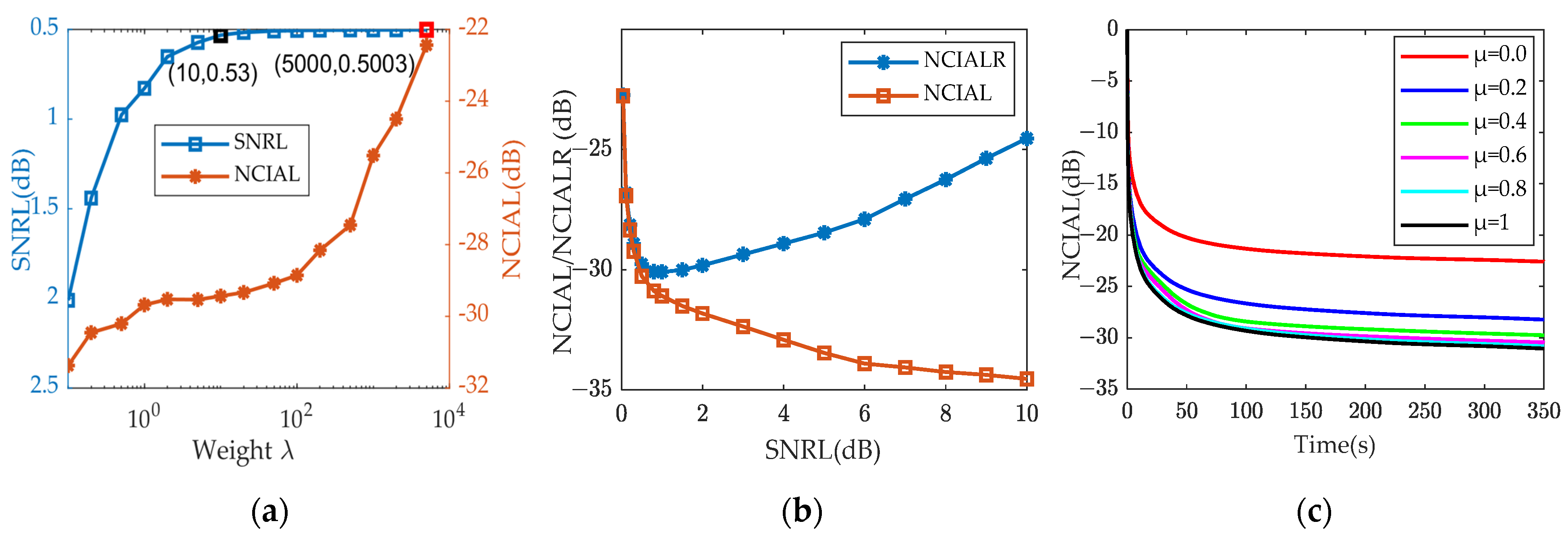
The influence of the weighting factor λ on the statistical mean of actual SNR loss and NCIAL is shown in Figure 4a, as can be seen, the actual SNR loss decreases as the weight λ increases and gradually approaches the predefined SNRL. Specifically, when λ = 10, the SNR loss is 0.53   d B, and when λ = 5000, it is 0.5003   d B. To precisely control the SNR loss, the weight factor λ should be chosen to be large enough. However, an excessively large weight factor limits the suppression performance of CIAL on the contrary. Therefore, the choice of weight factor λ should balance the control accuracy of SNR loss and CIAL suppression. Fortunately, for this example, the weight factor λ can be chosen between 1 and 1000.
The NCIAL versus the SNRL is further analyzed in the following by setting λ = 100 and μ = [ 0.0   0.1   0.2   0.4   0.6   0.8   1   1.5   2   3   4   5   6   7   8   9   10 ] . Figure 4b demonstrates the optimization results of the NCIAL and NCIAL ratio (NCIALR, the sum of NCIAL (dB) and SNRL (dB) representing the suppression of NCIAL relative to the peak value of pulse compression) versus SNRL. It is not difficult to find that the NCIAL can be further suppressed as the SNRL increases. However, the NCIALR cannot be further suppressed when the SNRL is greater than 1.5   d B. This is because although the NCIAL suppression performance is improved as the SNRL increases, the peak value of pulse compression decreases faster than the NCIAL decreases when the SNRL exceeds a certain level. Thus, some conclusions can be drawn according to the simulations for improving the practical application significance of our algorithm, e.g., in high SNR situations, SNRL can reach its minimum point (it represents the SNRL value corresponding to the lowest NCIALR) to improve orthogonality and reduce the pulse compression sidelobe of the waveforms. When in low-SNR situations, SNRL should be less than the minimum point.
The corresponding NCIAL evolution curves with respect to time under different μ are presented in Figure 4c, as can be noted that even a slight SNR loss can also make our algorithm achieve good performance in a short time.

4.2. Doppler Effect Analysis

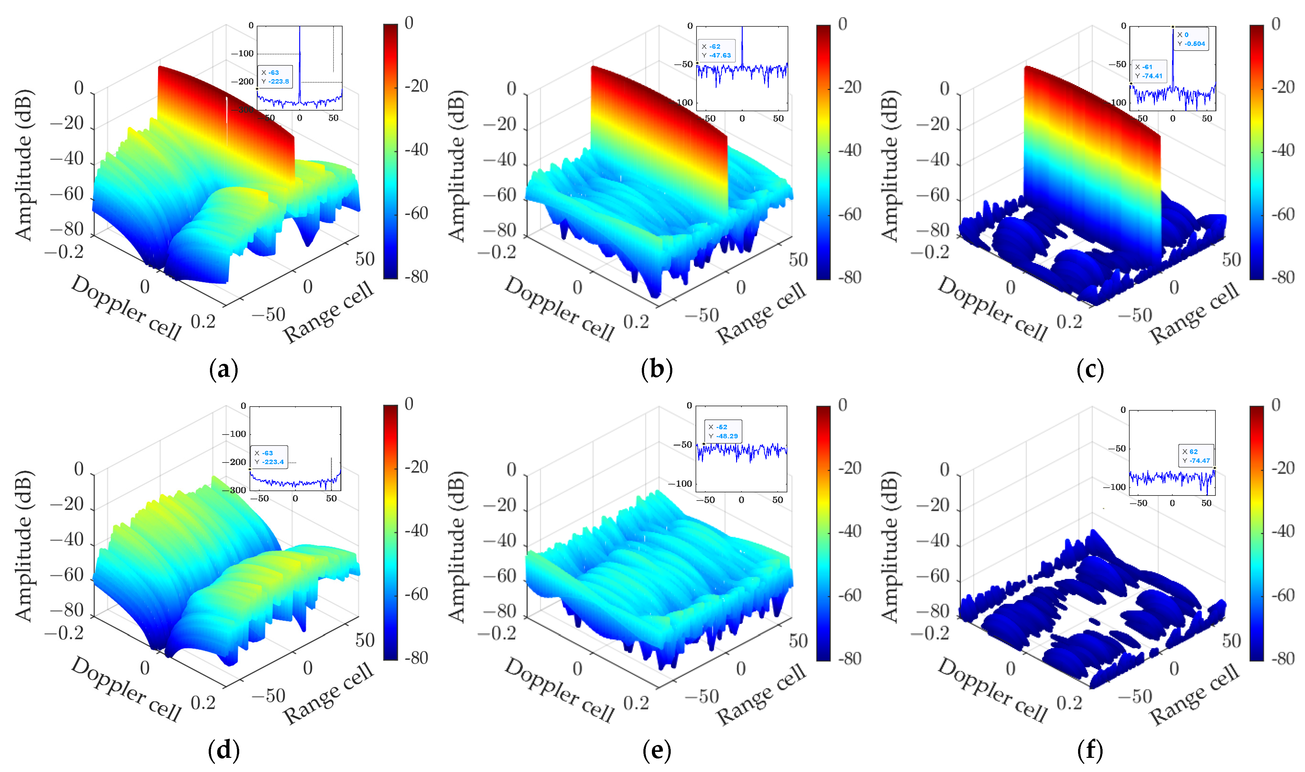
Example 4: In this subsection, we compare the performance of UOCCSs designed by different algorithms on Doppler resilience. Figure 5 shows the AFs of CCS designed by the MM-CCS algorithm [34], the L-BFGS algorithm [35], and our algorithm. The subfigures in Figure 5a–f shows the zero-Doppler cuts of the AFs. For all algorithms, the waveforms are optimized by 10,000 iterations or 600 s. Here, N = 64, K = 16, the normalized DFR f 0.2 ,   0.2 , μ = 0.5 , and λ = 10 are used.
It can be observed that the UOCCS along with the receiving filter designed by our algorithm realizes a stable low PSL for both the Auto-AF and the Cross-AF within the given normalized DFR, but this is not the case for both the MM-CCS algorithm and the L-BFGS algorithm. Specifically, the mean normalized sidelobes are about 47.53   d B for the MM-CCS, 56.52   d B for the L-BFGS, and 81.07   d B for our algorithm. The MM-CCS sequence has good ambiguity function properties only in a narrow DFR range. Meanwhile, the actual SNR loss of 0.504 dB of the designed CCS using our algorithm is almost equal to the predefined value (0.5 dB), and the sidelobes and orthogonality of the CCS do not fluctuate significantly in the normalized DFR f [−0.2, 0.2]. The reason for this is that the objective function in (21) is an integration sum of AFs with different discrete Doppler frequency shift f q , the sidelobes, and the orthogonality for each discrete frequency shift f q are optimized equally.

5. Experimental Validation

To verify the performance of the UOCCS waveforms and receiving filters designed by the proposed algorithm more rigorously, practical experiments are carried out using the hardware system as shown in Figure 6a, and the performance of our algorithm is compared with that of the MM-CCS [34] and the L-BFGS algorithm [35]. The block diagram of the experimental system is shown in Figure 6b. The hardware parameters are listed in Table 2. Specifically, in the transmitted part, the designed H and V polarization waveforms are obtained by first generating the base-band waveforms using two 14-bit digital-to-analog converter (DAC) with 2.5 GHz sampling rate, which are then up-converted to Ku band and amplified. Then, the transmitted signals are directly fed into the H and V polarization ports of the orthogonal mode transducer (OMT) of polarization isolation below 50   d B , respectively, to form the simultaneously polarized radar signal. Another OMT is connected to the former OMT through a section of circular waveguide and its two output ports are connected to a two-channel receiver of 200 MHz bandwidth before a 60 dB attenuator is applied. In the two-channel receiver, the attenuated signal is down-converted to in-phase and quadrature-phase (IQ) base-band signals and finally digitized by a 12-bit two-channel analog-to-digital converter (ADC) of 500 MHz sampling rate. We should point out that different Doppler shifts have been modulated into the originally transmitted H and V signals for evaluating the performances of different waveforms on the Doppler tolerance.
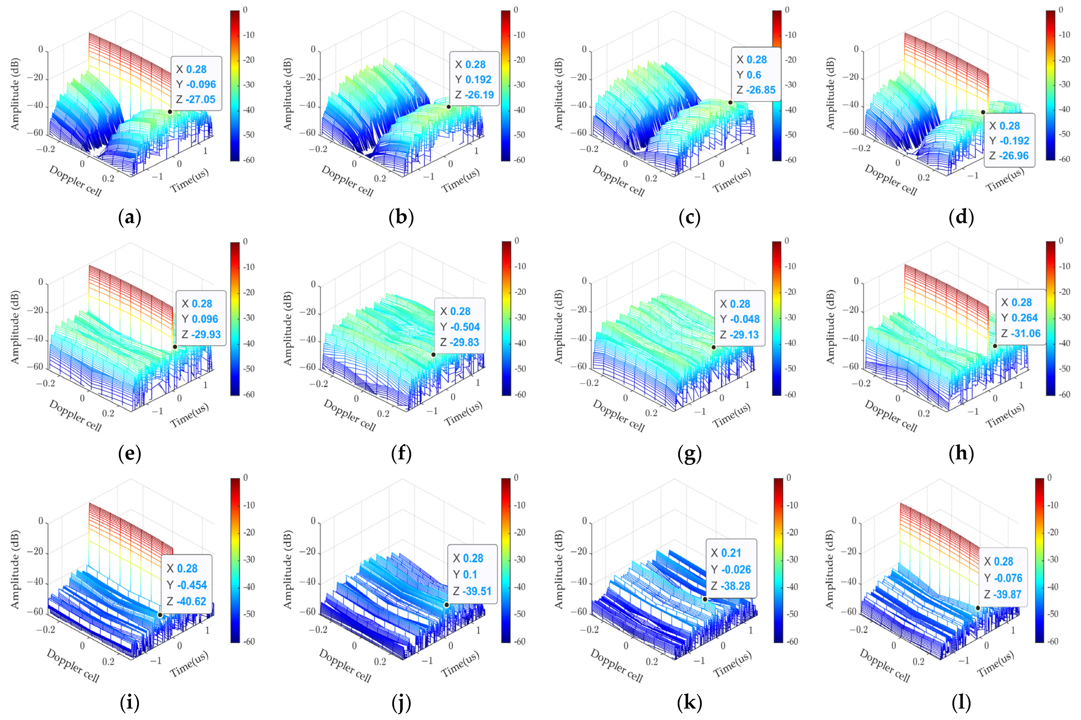
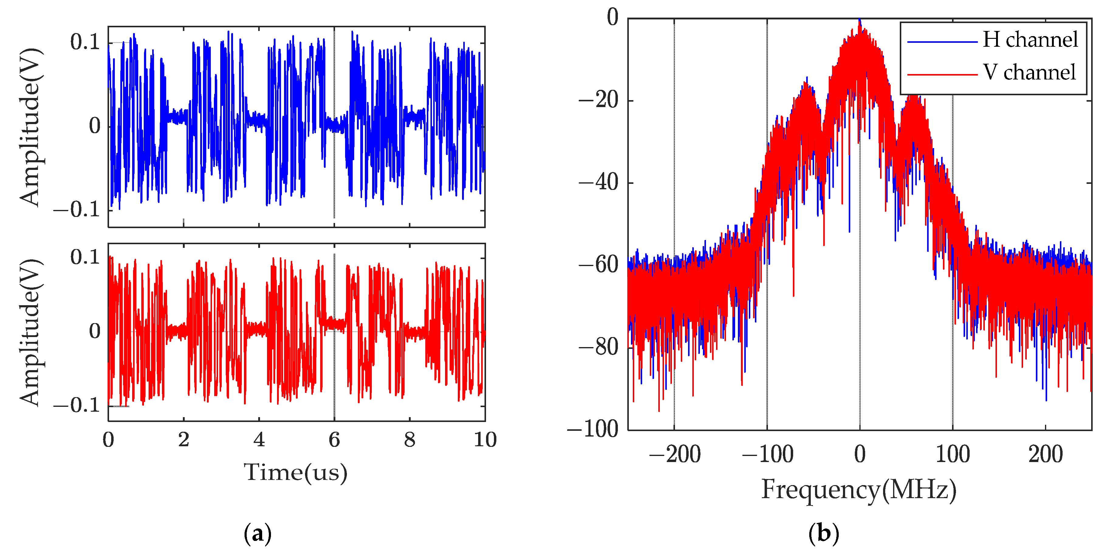
In the practical experiment, another set of UOCCS waveforms and receiving filters with N = 64 and K = 5 by the MM-CCS algorithm [34], the L-BFGS algorithm [35] and our algorithm are implemented into the hardware, whose bandwidth B, pulse duration T p ( N / B ) , PRI ( T r ) as well as the CPI are, respectively, set as 40   M H z , 1.6   μ s , 2.1   μ s ,   and 10   μ s . The SNR loss μ = 0.5   d B is considered for our algorithm. Figure 7 shows the simulated AFs before implementation. Figure 8 presents the in-phase components of the sampled waveforms from our waveforms at the receiver end and the corresponding spectrums. Figure 9 presents the AFs of practically implemented waveforms through the transmitter–receiver chain.
Both Figure 7 and Figure 9 demonstrate that the waveforms designed by our method outperform others when the Doppler frequencies are considered although the waveform of [34] performs the best when the Doppler frequency is zero. If we compare Figure 7 and Figure 9, it is easy to note that the real implemented results of all waveforms are obviously not as good as the simulated, and this is mainly due to the following factors: (1) the filter (combination of several filters both in the transmitter channel and in the receiver channel) is applied in hardware but not in the simulation. (2) the IQ imbalance of the transmitter–receiver chain, and the nonlinear effect. To manifest the first factor, another simulation experiment is conducted with a filter applied, which is derived from measurements. To compare the performances, we list the maximum normalized sidelobes (MNSLs) of all waveforms in Table 3, where Simulated 1 denotes the results without filter, while Simulated 2 denotes the results with the filter applied. One can observe the following facts from Table 3: (1) Although the waveform of [34] performs the best when f q = 0 , its MNSL is affected by the filter mostly, and when f q > 0.07 , the performances of HH, HV, VH, and VV degrade dramatically. (2) Let us take the HH case for example, for the waveform of [34], the measured MNSL of HH increases from 39.41 to 25.7 as f q increases from 0 to 0.28. For the waveform of [35], the measured MNSL increases from 31.81 to 29.28 , while the measured MNSL of our waveform increases from 37.54 to just 36.88 . (3) The same trend is observed for HV, VH, and VV polarizations. (4) The degradation of performances by imperfect factors of hardware is less than 2 dB for all waveforms. All in all, our waveforms have the best Doppler tolerance performance.
We must emphasize that the digitization errors of DAC and ADC have been considered in the simulation. We also need to further explain the two effects of the filter on the AFs: (1) the signal band is reduced; however the large signal bandwidth is very helpful for obtaining low PSL and ISL. (2) the phase of the waveform can be influenced by the filter resulting in waveform distortion [51,52].

6. Conclusions

The problem for the joint design of a pair of UOCCSs and receiving filters with high Doppler tolerance for SPR is focused on under the mismatch constraint. A nonconvex objective function is constructed based on AF, which is optimized with respect both to the CIAL and the orthogonality within the defined DFR by adopting an alternatively iterative scheme implemented via the MM method. The main steps, i.e., the computation of Toeplitz matrix-vector multiplication terms in the proposed algorithms, are implemented via the FFT with high computational efficiency. Moreover, SQUAREM is adopted to accelerate the algorithm. Compared with the representative MM-CCS and L-BFGS algorithms, the proposed algorithm achieves a significant improvement in the optimized performance and the convergence speed. Simulations are carried out to demonstrate that the CIAL can be significantly suppressed at the cost of appropriate SNR loss by jointly designing the waveforms and the receiving filters. Moreover, a practical experiment based on the transmitter–receiver hardware chain is conducted to validate the design, and the same superior performance of our design has been demonstrated when compared with other designs.
The unimodular constraint on the transmitted CCS is currently considered in this work. Some more general constraints (such as the discrete phase constraint [53], or peak-to-average ratio [54]) may also be applicable. We plan to try some other reformulations on the joint problem with more general constraints applied and more suitable algorithms developed to incorporate into the optimization framework in the future. At last, we should point out that the proposed framework can be extended to design other waveforms for MIMO radar and multichannel communication systems as well, where orthogonal sequences are highly desired.

Author Contributions

Conceptualization, Y.C., Y.Z. and D.L.; methodology, Y.C. and Y.Z.; validation, Y.C. and J.Y.; formal analysis, Y.C. and D.L.; writing—original draft preparation, Y.C.; writing—review and editing, Y.C. and Y.Z. and J.Y.; All authors have read and agreed to the published version of the manuscript.

Funding

This work was funded by the National Natural Science Foundation of China under Grant 61971402.

Data Availability Statement

Not applicable.

Acknowledgments

The authors acknowledge the equipment and technical support provided by the National Space Science Center, Chinese Academy of Sciences. We also appreciate the anonymous reviewers.

Conflicts of Interest

The authors declare no conflict of interest.

Appendix A

1. Derivation of Equation (30):
R e v e c P m m ~ q Q m m ~ q v e c P m m ~ q ( l ) = R e n = 1 L L 1 w m , m ~ n , f q v e c P m m ~ q v e c T n v e c T n v e c P m m ~ q ( l ) = R e n = 1 L L 1 w m , m ~ n , f q T r T n P m m ~ q T r P m m ~ q ( l ) T n = R e n = 1 L L 1 w m , m ~ n , f q T r T n u m q v m ~ T r v m ~ ( l ) u m q T n = R e n = 1 L L 1 w m , m ~ n , f q v m ~ T r v m ~ ( l ) u m q T n T n u m q = R e n = 1 L L 1 w m , m ~ n , f q v m ~ u m q T n v m ~ ( l ) T n u m q = R e v m ~ n = 1 L L 1 w m , m ~ n , f q v m ~ ( l ) T n u m q * T n u m q = R e v m ~ n = 1 L L 1 w m , m ~ n , f q A u m , v m ~ l n , f q * T n u m q = R e v m ~ R m m ~ l q u m q
where
R m m ~ l q = n = 1 L L 1 w m , m ~ n , f q A u m , v m ~ l n , f q * T n
2. Derivation of Equation (36):
R e v e c P m m ~ q Q m m ~ q v e c P m m ~ q ( l ) = R e n = 1 L L 1 w m , m ~ n , f q v e c P m m ~ q v e c T n v e c T n v e c P m m ~ q ( l ) = R e n = 1 L L 1 w m , m ~ n , f q T r T n P m m ~ q T r P m m ~ q ( l ) T n = R e n = 1 L L 1 w m , m ~ n , f q T r T n u m q v m ~ T r v m ~ u m q ( l ) T n = R e n = 1 L L 1 w m , m ~ n , f q v m ~ T r v m ~ u m q ( l ) T n T n u m q = R e n = 1 L L 1 w m , m ~ n , f q v m ~ u m q ( l ) T n v m ~ T n u m q = R e u m q n = 1 L L 1 w m , m ~ n , f q T n v m ~ T n u m q ( l ) v m ~ = R e u m q n = 1 L L 1 w m , m ~ n , f q A u m l , v m ~ n , f q T n v m ~ = R e u m q R m l m ~ q v m ~
where
R m l m ~ q = n = 1 L L 1 w m , m ~ n , f q A u m ( l ) , v m ~ n , f q T n

References

  1. Lee, J.S.; Pottier, E. Polarimetric Radar Imaging: From Basics to Applications; CRC: Boca Raton, FL, USA, 2009. [Google Scholar]
  2. Hurtado, M.; Nehorai, A. Polarimetric detection of targets in heavy inhomogeneous clutter. IEEE Trans. Signal Process. 2008, 56, 1349–1361. [Google Scholar] [CrossRef]
  3. Liang, L.; Zhang, Y.; Li, D. A novel method for polarization orientation angle estimation over steep terrain and comparison of deorientation algorithms. IEEE Trans. Geosci. Remote Sens. 2020, 59, 4790–4801. [Google Scholar] [CrossRef]
  4. Liang, L.; Zhang, Y.; Li, D. Fast Huynen–Euler Decomposition and its Application in Disaster Monitoring. IEEE J. Sel. Top. Appl. Earth Obs. Remote Sens. 2021, 14, 4231–4243. [Google Scholar] [CrossRef]
  5. Giuli, D.; Fossi, M.; Facheris, L. Radar target scattering matrix measurement through orthogonal signals. IEE Proc. F Radar Signal Process. 1993, 140, 233–242. [Google Scholar] [CrossRef]
  6. Li, C.; Li, Y.; Yang, Y.; Pang, C.; Wang, X. Moving target’s scattering matrix estimation with a polarimetric radar. IEEE Trans. Geosci. Remote Sens. 2020, 58, 5540–5551. [Google Scholar] [CrossRef]
  7. Wang, F.; Yin, J.; Pang, C.; Li, Y.; Wang, X. A unified framework of Doppler resilient sequences design for simultaneous polarimetric radars. IEEE Trans. Geosci. Remote Sens. 2022, 60, 5109615. [Google Scholar] [CrossRef]
  8. Wang, X. Study on Wideband Polarization Information Processing. Ph.D. Thesis, Graduate School of National University of Defense Technology, Changsha, China, 1999. [Google Scholar]
  9. Wang, X.; Li, Y.; Dai, H.; Chang, Y.; Dai, D.; Ma, L.; Liu, Y. Research on instantaneous polarization radar system and external experiment. Chinese Sci. Bull. 2010, 55, 1560–1567. [Google Scholar] [CrossRef]
  10. Wang, F.; Pang, C.; Li, Y.; Wang, X. Algorithms for designing unimodular sequences with high Doppler tolerance for simultaneous fully polarimetric radar. Sensors 2018, 18, 905. [Google Scholar] [CrossRef] [Green Version]
  11. Chen, Z.; Liang, J.; Song, K.; Yang, Y.; Deng, X. On designing good doppler tolerance waveform with low PSL of ambiguity function. Signal Process. 2023, 210, 109075. [Google Scholar] [CrossRef]
  12. Hu, C.; Chen, Z.; Dong, X.; Cui, C. Multistatic geosynchronous SAR resolution analysis and grating lobe suppression based on array spatial ambiguity function. IEEE Trans. Geosci. Remote Sens. 2020, 58, 6020–6038. [Google Scholar] [CrossRef]
  13. Cui, G.; Fu, Y.; Yu, X.; Li, J. Local ambiguity function shaping via unimodular sequence design. IEEE Signal Process. Lett. 2017, 24, 977–981. [Google Scholar] [CrossRef]
  14. Ye, Z.; Zhou, Z.; Fan, P.; Liu, Z.; Lei, X.; Tang, X. Low ambiguity zone: Theoretical bounds and Doppler-resilient sequence design in integrated sensing and communication systems. IEEE J. Sel. Areas Commun. 2022, 40, 1809–1822. [Google Scholar] [CrossRef]
  15. He, H.; Stoica, P.; Li, J. Designing unimodular sequence sets with good correlations-Including an application to MIMO radar. IEEE Trans. Signal Process. 2009, 57, 4391–4405. [Google Scholar] [CrossRef]
  16. Li, C.; Yang, Y.; Li, Y.; Wang, X. Frequency calibration for the scattering matrix of the simultaneous polarimetric radar. IEEE Geosci. Remote Sens. Lett. 2018, 15, 429–433. [Google Scholar] [CrossRef]
  17. Zheng, Z.; Zhang, Y.; Peng, X.; Xie, H.; Chen, J.; Mo, J.; Sui, Y. MIMO Radar Waveform Design for Multipath Exploitation Using Deep Learning. Remote Sens. 2023, 15, 2747. [Google Scholar] [CrossRef]
  18. Li, C.; Yang, Y.; Pang, C.; Li, Y.; Wang, X. A simultaneous polarimetric measurement scheme using one amplitude modulation waveform. IEEE Geosci. Remote Sens. Lett. 2019, 17, 72–76. [Google Scholar] [CrossRef]
  19. Liu, B. Orthogonal discrete frequency-coding waveform set design with minimized autocorrelation sidelobes. IEEE Trans. Aerosp. Electron. Syst. 2009, 45, 1650–1657. [Google Scholar] [CrossRef]
  20. Yu, X.; Alhujaili, K.; Cui, G.; Monga, V. MIMO radar waveform design in the presence of multiple targets and practical constraints. IEEE Trans. Signal Process. 2020, 68, 1974–1989. [Google Scholar] [CrossRef]
  21. Zhang, Y.; Liao, G.; Xu, J.; Lan, L. Mainlobe Deceptive Jammer Suppression Based on Quadratic Phase Coding in FDA-MIMO Radar. Remote Sens. 2022, 14, 5831. [Google Scholar] [CrossRef]
  22. Liu, T.; Sun, J.; Wang, G.; Lu, Y. A Multi-Objective Quantum Genetic Algorithm for MIMO Radar Waveform Design. Remote Sens. 2022, 14, 2387. [Google Scholar] [CrossRef]
  23. Stoica, P.; He, H.; Li, J. New algorithms for designing unimodular sequences with good correlation properties. IEEE Trans. Signal Process. 2009, 57, 1415–1425. [Google Scholar] [CrossRef] [Green Version]
  24. Song, J.; Babu, P.; Palomar, D.P. Sequence design to minimize the weighted integrated and peak sidelobe levels. IEEE Trans. Signal Process. 2015, 64, 2051–2064. [Google Scholar] [CrossRef] [Green Version]
  25. Feng, X.; Zhao, Z.; Li, F.; Cui, W.; Zhao, Y. Radar Phase-Coded Waveform Design with Local Low Range Sidelobes Based on Particle Swarm-Assisted Projection Optimization. Remote Sens. 2022, 14, 4186. [Google Scholar] [CrossRef]
  26. He, H.; Stoica, P.; Li, J. On Aperiodic-Correlation Bounds. IEEE Signal Process. Lett. 2010, 17, 253–256. [Google Scholar] [CrossRef]
  27. Pezeshki, A.; Calderbank, A.R.; Moran, W.; Howard, S.D. Doppler Resilient Golay Complementary Waveforms. IEEE Trans. Inf. Theory 2008, 54, 4254–4266. [Google Scholar] [CrossRef] [Green Version]
  28. Li, H.; Liu, Y.; Liao, G.; Chen, Y. Joint Radar and Communications Waveform Design Based on Complementary Sequence Sets. Remote Sens. 2023, 15, 645. [Google Scholar] [CrossRef]
  29. Chen, H.H.; Yeh, Y.C.; Bi, Q.; Jamalipour, A. On a MIMO-based open wireless architecture: Space-time complementary coding. IEEE Commun. Mag. 2007, 45, 104–112. [Google Scholar] [CrossRef]
  30. Song, Y.; Wang, Y.; Xie, J.; Yang, Y.; Tian, B.; Xu, S. Ultra-Low Sidelobe Waveforms Design for LPI Radar Based on Joint Complementary Phase-Coding and Optimized Discrete Frequency-Coding. Remote Sens. 2022, 14, 2592. [Google Scholar] [CrossRef]
  31. Levanon, N.; Cohen, I.; Itkin, P. Complementary pair radar waveforms–evaluating and mitigating some drawbacks. IEEE Aerosp. Electron. Syst. Mag. 2017, 32, 40–50. [Google Scholar] [CrossRef]
  32. Aubry, A.; De Maio, A.; Jiang, B.; Zhang, S. Ambiguity function shaping for cognitive radar via complex quartic optimization. IEEE Trans. Signal Process. 2013, 61, 5603–5619. [Google Scholar] [CrossRef]
  33. Tang, J.; Zhang, N.; Ma, Z.; Tang, B. Construction of Doppler Resilient Complete Complementary Code in MIMO Radar. IEEE Trans. Signal Process. 2014, 62, 4704–4712. [Google Scholar] [CrossRef]
  34. Song, J.; Babu, P.; Palomar, D.P. Sequence set design with good correlation properties via majorization-minimization. IEEE Trans. Signal Process. 2016, 64, 2866–2879. [Google Scholar] [CrossRef] [Green Version]
  35. Wang, F.; Pang, C.; Wu, H.; Li, Y.; Wang, X. Designing Constant Modulus Complete Complementary Sequence With High Doppler Tolerance for Simultaneous Polarimetric Radar. IEEE Signal Process. Lett. 2019, 26, 1837–1841. [Google Scholar] [CrossRef]
  36. Xu, L.; Zhou, S.; Liu, H. Simultaneous optimization of radar waveform and mismatched filter with range and delay-Doppler sidelobes suppression. Digit. Signal Process. 2018, 83, 346–358. [Google Scholar] [CrossRef]
  37. Wang, Y.C.; Dong, L.; Xue, X.; Yi, K.-C. On the Design of Constant Modulus Sequences with Low Correlation Sidelobes Levels. IEEE Commun. Lett. 2012, 16, 462–465. [Google Scholar] [CrossRef]
  38. Wu, L.; Babu, P.; Palomar, D.P. Transmit waveform/receive filter design for MIMO radar with multiple waveform constraints. IEEE Trans. Signal Process. 2017, 66, 1526–1540. [Google Scholar] [CrossRef]
  39. Beauchamp, R.M.; Tanelli, S.; Peral, E.; Chandrasekar, V. Pulse compression waveform and filter optimization for spaceborne cloud and precipitation radar. IEEE Trans. Geosci. Remote Sens. 2016, 55, 915–931. [Google Scholar] [CrossRef]
  40. Wang, F.; Xia, X.-G.; Pang, C.; Cheng, X.; Li, Y.; Wang, X. Joint Design Methods of Unimodular Sequences and Receiving Filters with Good Correlation Properties and Doppler Tolerance. IEEE Trans. Geosci. Remote Sens. 2022, 61, 5100214. [Google Scholar] [CrossRef]
  41. Zhou, K.; Quan, S.; Li, D.; Liu, T.; He, F.; Su, Y. Waveform and filter joint design method for pulse compression sidelobe reduction. IEEE Trans. Geosci. Remote Sens. 2022, 60, 5107615. [Google Scholar] [CrossRef]
  42. Wang, F.; Feng, S.; Yin, J.; Pang, C.; Li, Y.; Wang, X. Unimodular sequence and receiving filter design for local ambiguity function shaping. IEEE Trans. Geosci. Remote Sens. 2022, 60, 5113012. [Google Scholar] [CrossRef]
  43. Xiong, W.; Hu, J.; Zhong, K.; Sun, Y.; Xiao, X.; Zhu, G. MIMO Radar Transmit Waveform Design for Beampattern Matching via Complex Circle Optimization. Remote Sens. 2023, 15, 633. [Google Scholar] [CrossRef]
  44. Zhou, K.; Li, D.; Quan, S.; Liu, T.; Su, Y.; He, F. SAR waveform and mismatched filter design for countering interrupted-sampling repeater jamming. IEEE Trans. Geosci. Remote Sens. 2022, 60, 5214514. [Google Scholar] [CrossRef]
  45. Yang, J.; Zhou, J.; Liu, L.; Li, Y. A novel strategy of pareto-optimal solution searching in multi-objective particle swarm optimization (MOPSO). Comput. Math. Appl. 2009, 57, 1995–2000. [Google Scholar] [CrossRef] [Green Version]
  46. Everett, H. Generalized Lagrange multiplier method for solving problems of optimum allocation of resources. Oper. Res. 1963, 11, 399–417. [Google Scholar] [CrossRef]
  47. Raydan, M.; Svaiter, B.F. Relaxed steepest descent and Cauchy-Barzilai-Borwein method. Comput. Optim. Appl. 2002, 21, 155–167. [Google Scholar] [CrossRef]
  48. Varadhan, R.; Roland, C. Simple and globally convergent methods for accelerating the convergence of any EM algorithm. Scand. J. Stat. 2008, 35, 335–353. [Google Scholar] [CrossRef]
  49. Roughgarden, T. Beyond the Worst-Case Analysis of Algorithms; Cambridge University Press: Cambridge, UK, 2021. [Google Scholar]
  50. He, H.; Li, J.; Stoica, P. Waveform Design for Active Sensing Systems: A Computational Approach; Cambridge University Press: Cambridge, UK, 2012. [Google Scholar]
  51. Chen, R.; Cantrell, B. Highly bandlimited radar signals. In Proceedings of the 2002 IEEE Radar Conference, Long Beach, CA, USA, 25 April 2002. [Google Scholar]
  52. Liu, J.; Zhang, Y.; Dong, X. Linear-FM random radar waveform compressed by dechirping method. IET Radar Sonar Navig. 2019, 13, 1107–1115. [Google Scholar] [CrossRef]
  53. Chen, Y.; Lin, R.; Cheng, Y.; Li, J. Joint Design of Periodic Binary Probing Sequences and Receive Filters for PMCW Radar. IEEE Trans. Signal Process. 2022, 70, 5996–6010. [Google Scholar] [CrossRef]
  54. De Maio, A.; Huang, Y.; Piezzo, M.; Zhang, S.; Farina, A. Design of optimized radar codes with a peak to average power ratio constraint. IEEE Trans. Signal Process. 2011, 59, 2683–2697. [Google Scholar] [CrossRef]
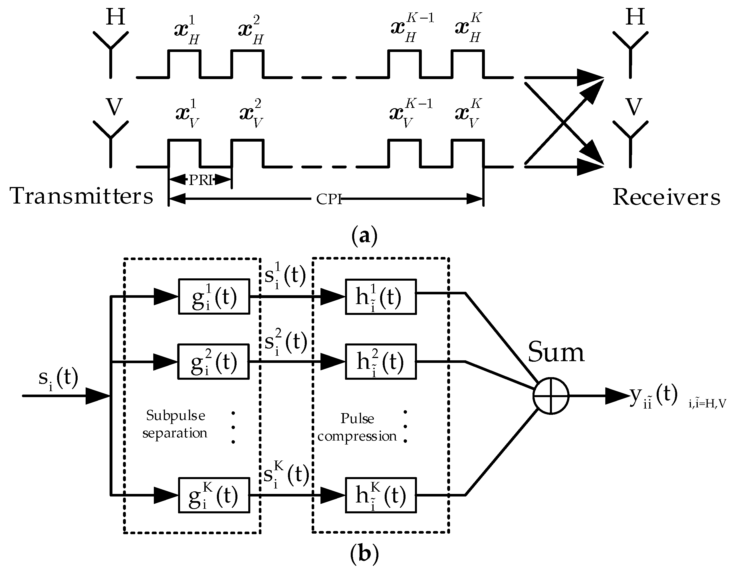
Figure 1. (a) Transmitting and receiving radar signal by simultaneously polarimetric radar. (b) Signal-processing procedure [28].
Remotesensing 15 03877 g001
Figure 2. Evolutions of the NCIAL along with the running time.
Remotesensing 15 03877 g002
Figure 3. Zero-Doppler cuts of the Auto- and Cross-AF of CCSs with N = 64 and K = 2, 4, 5, 6.
Remotesensing 15 03877 g003
Figure 4. Influences of the weight λ and the SNR loss μ on the NCIAL suppression. (a) Influence of the weighting factor λ ; (b) Influence of the SNR loss μ ; (c) NCIAL evolution curves with respect to time.
Remotesensing 15 03877 g004
Figure 5. AFs of waveforms obtained by different algorithms. (a) Auto-AF by [34]; (b) Auto-AF by [35]; (c) Auto-AF by ours; (d) Cross-AF by [34]; (e) Cross-AF by [35]; (f) Cross-AF by ours.
Remotesensing 15 03877 g005
Figure 6. Experiment hardware system, (a) Photograph; (b) Block diagram.
Remotesensing 15 03877 g006
Figure 7. AFs of simulated waveforms from different polarimetric channels before implementation. (a) HH by [34]; (b) HV by [34]; (c) VH for [34]; (d) VV by [34]; (e) HH by [35]; (f) HV by [35]; (g) VH by [35]; (h) VV by [35]; (i) HH by ours; (j) HV by ours; (k) VH by ours; (l) VV by ours.
Remotesensing 15 03877 g007
Figure 8. Sampled waveforms by A/D convertor from our waveforms. (a) In-phase components in the time domain; (b) Spectrums of the sampled signals.
Remotesensing 15 03877 g008
Figure 9. AFs of practically implemented waveforms through the transmitter–receiver chain. (a) HH by [34]; (b) HV by [34]; (c) VH for [34]; (d) VV by [34]; (e) HH by [35]; (f) HV by [35]; (g) VH by [35]; (h) VV by [35]; (i) HH by ours; (j) HV by ours; (k) VH by ours; (l) VV by ours.
Remotesensing 15 03877 g009
Table 1. Mathematical Notations.
NotationMeaning
· T the transposition of a vector/matrix
· * the conjugate of a complex number/vector/matrix
· the conjugate transpose of a vector/matrix
· the modulus of a complex number
· the l 2 -norm of a vector
R e · the real part of a complex number
T r · the trace of a matrix
v e c · the stacking vectorization of a matrix
D i a g x a diagonalized matrix of x
Hadamard product
0 N an all-zero column vector with dimension N
1 N an all-one column vector with dimension N
0 L × L an all-zero matrix with dimension L × L
I L the identity matrix with dimension L × L
Table 2. Parameters of the experimental system.
ParameterQuantity
Carrier Frequency f c 13.58 GHz
Waveform bandwidth B40 MHz
Pulse duration T p 1.6   μ s
Pulse PRI T r 2.1   μ s
CPI 10   μ s
Code length N 64
Pulse number K 5
A/D sampling rate500 MHz
ADC resolution12 bit
Table 3. Comparison of the MNSLs (in dB) versus f q .
Waveform of [34]Waveform of [35]Our Waveform
HHHVVHVVHHHVVHVVHHHVVHVV
f q = 0 Simulated 1−61.23−60.19−60.19−60.65−34.10−33.56−33.56−34.20−42.91−42.29−41.56−42.87
Simulated 2−40.81−39.85−41.02−40.96−32.17−33.20−32.28−32.98−38.11−38.46−39.29−38.68
Measured−39.41−39.32−38.41−39.17−31.81−31.71−31.44−31.96−37.54−37.13−38.17−37.76
f q = 0.07 Simulated 1−38.83−37.74−38.06−38.31−32.66−32.70−32.78−32.73−42.04−41.72−40.10−43.17
Simulated 2−35.80−35.36−34.02−37.27−32.01−32.45−32.03−32.66−38.41−39.45−38.84−39.62
Measured−34.17−35.55−33.78−36.34−31.01−30.88−31.76−32.05−37.90−38.13−36.88−38.73
f q = 0.14 Simulated 1−32.89−31.70−31.10−32.60−31.18−30.93−31.32−32.45−41.65−41.34−39.16−42.55
Simulated 2−32.19−30.56−29.72−33.04−30.90−30.47−30.36−32.29−38.61−38.73−37.59−37.53
Measured−30.04−30.64−30.39−32.47−30.64−30.35−30.02−30.19−38.29−37.82−36.53−37.16
f q = 0.21 Simulated 1−29.58−28.37−27.80−29.25−30.00−30.11−30.2−33.25−41.27−40.39−38.28−41.13
Simulated 2−29.18−28.06−27.26−29.51−29.13−29.74−29.18−32.73−38.42−38.97−38.42−37.96
Measured−27.90−28.0−27.19−29.47−29.54−29.33−29.42−30.43−37.36−36.73−37.33−36.81
f q = 0.28 Simulated 1−27.05−26.19−26.85−26.96−29.93−29.83−29.13−31.06−40.62−39.51−38.96−39.87
Simulated 2−26.84−26.30−25.56−27.12−28.98−29.56−28.65−30.91−38.35−38.54−38.59−37.49
Measured−25.70−26.00−25.57−26.25−29.28−29.87−28.19−29.22−36.88−37.08−37.89−36.30
Disclaimer/Publisher’s Note: The statements, opinions and data contained in all publications are solely those of the individual author(s) and contributor(s) and not of MDPI and/or the editor(s). MDPI and/or the editor(s) disclaim responsibility for any injury to people or property resulting from any ideas, methods, instructions or products referred to in the content.